1
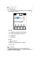
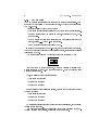
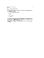
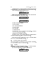
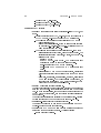
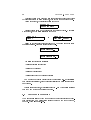
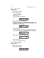
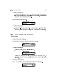
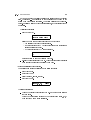
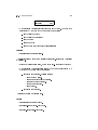
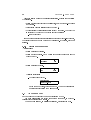
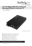
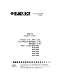
TIP2-Vatersay platform
User manual
www.gir.fr/en
[email protected]
Version 1.0-1, january 2011
2
c 2004-2011 klervi. All rights reserved.
Copyright °
Any reproduction or translation of part or totality of this manual is
forbidden without any prior written authorization from klervi.
The contents of this document are given for information only. Klervi
is in no way liable for any mistake that could have slipped into the
text.
Contents
1 Overview
1.1
1.2
Management unit . .
1.1.1 Hardware . .
1.1.2 Software . . .
1.1.3 TIP modules
Other modules . . .
.
.
.
.
.
.
.
.
.
.
.
.
.
.
.
.
.
.
.
.
.
.
.
.
.
.
.
.
.
.
.
.
.
.
.
.
.
.
.
.
.
.
.
.
.
.
.
.
.
.
.
.
.
.
.
.
.
.
.
.
.
.
.
.
.
.
.
.
.
.
.
.
.
.
.
.
.
.
.
.
.
.
.
.
.
.
.
.
.
.
.
.
.
.
.
.
.
.
.
.
.
.
.
.
.
.
.
.
.
.
.
.
.
.
.
Access to setup mode . .
Conguration parameters
2.2.1 Overview . . . . .
2.2.2 Parameters list . .
Modules and adresses test
.
.
.
.
.
.
.
.
.
.
.
.
.
.
.
.
.
.
.
.
.
.
.
.
.
.
.
.
.
.
.
.
.
.
.
.
.
.
.
.
.
.
.
.
.
.
.
.
.
.
.
.
.
.
.
.
.
.
.
.
.
.
.
.
.
.
.
.
.
.
.
.
.
.
.
.
.
.
.
.
.
.
.
.
.
.
.
.
.
.
.
.
.
.
.
.
.
.
.
.
.
.
.
.
.
.
.
.
.
.
Access to test mode . . . . . . . . .
Platform information . . . . . . . . .
Modules test . . . . . . . . . . . . .
3.3.1 Pump module . . . . . . . . .
3.3.2 Terminal module . . . . . . .
3.3.3 GIR proximity reader module
3.3.4 M232 module . . . . . . . . .
3.3.5 Sub-modules . . . . . . . . .
3.3.6 Mifare reader module . . . .
Addresses test . . . . . . . . . . . . .
Specic modules conguration . . . .
.
.
.
.
.
.
.
.
.
.
.
.
.
.
.
.
.
.
.
.
.
.
.
.
.
.
.
.
.
.
.
.
.
.
.
.
.
.
.
.
.
.
.
.
.
.
.
.
.
.
.
.
.
.
.
.
.
.
.
.
.
.
.
.
.
.
.
.
.
.
.
.
.
.
.
.
.
.
.
.
.
.
.
.
.
.
.
.
.
.
.
.
.
.
.
.
.
.
.
.
.
.
.
.
.
.
.
.
.
.
.
.
.
.
.
.
.
.
.
.
.
.
.
.
.
.
.
.
.
.
.
.
.
.
.
.
.
.
.
.
.
.
.
.
.
.
.
.
.
.
.
.
.
.
.
.
.
.
.
.
.
.
.
.
.
.
.
.
.
.
.
.
.
.
.
.
2 Setup mode
2.1
2.2
2.3
.
.
.
.
.
.
.
.
.
.
3 Test mode
3.1
3.2
3.3
3.4
3.5
3
5
6
6
7
8
9
11
11
12
12
13
15
17
17
18
19
20
20
21
22
24
26
26
27
4
CONTENTS
Chapter 1
Overview
The TIP2-Vatersay platform is an hardware and software combination designed
to run embedded applications.
It provides services to allow an application to communicate with:
• a PC, via a serial, modem or network connection
• TIP modules (terminal, reader, pump. . . ), via a RS-485 connection
5
6
CHAPTER 1. OVERVIEW
1.1 Management unit
1.1.1 Hardware
AX management unit
The AX management unit is an old model used for the TIP2-Vatersay platform.
It is no longer used for new installations.
It has the following connectors:
Eth0
RJ−45
Eth1
RJ−45
COM1
Eth1
Eth0
UG Vatersay
TX+
TX−
RX+
RX−
Power
USB
COM2
GND
AC
AC
Power
Front panel:
• COM1 : Serial port 1, unused
• COM2 : Serial port 2, available for PC connection
• USB: USB port
• Power : Power LED
• Eth0 : LED indicating activity on the eth0 network interface
• Eth1 : LED indicating activity on the eth1 network interface
Rear panel:
• Eth0 : RJ45 connector, available for PC connection
• Eth1 : Unused
• TX+,TX-: Unused
• RX+,RX-: RS-485 connector, available for modules connection
• GND,AC : Power connector
• Power : Unused
1.1. MANAGEMENT UNIT
7
MX management unit
The MX management unit is the model currently used for new installations.
It has the following connectors:
RJ−45
USB
V− V+
Eth0
Power
Ready
Eth
UG Vatersay MX
COM1
COM2
COM3
COM4
RJ−45
RJ−45
RJ−45
RJ−45
Front panel:
• COM1 : Serial port 1, available for modules connection
• COM2 : Serial port 2, available for PC connection
• COM3 : Serial port 3
• COM4 : Serial port 4
Rear panel:
• V+,V-: Power connector
• Eth0 : RJ45 connector, available for PC connection
• USB: USB ports
1.1.2 Software
The TIP2-Vatersay platform is based on a Linux operating system.
Only the network services required for PC connection are running on the
platform. No other service is available.
8
CHAPTER 1. OVERVIEW
1.1.3 TIP modules
The TIP modules are electronic components that provide basic services. They
are meant to be controlled by the management unit, to which they are connected
by a RS-485 bus.
There are dierent types of TIP modules:
• Terminal module: controls a screen and a keyboard for human interaction.
• Reader module: reads GIR proximity badges, controls two LEDS, commands a relay.
• M232 module: provides communication with an external device (badge
reader, printer, . . . ) via a RS-232 connection.
• Pump module: controls a fuel delivery pump.
In order to communicate on the RS-485 bus, each module has its own address,
that can be congured using four conguration switches, giving sixteen possible
values (from 0 to 15).
The picture below shows a module congured with address 3 (1+2):
0
1
0
1
0
1
0
1
11
00
00
11
0
1
0
1
00
11
00
11
00
11
00
11
1 2 3 4
on on off off
For the system to operate properly, it must be possible to identify each
module connected to the RS-485 bus in a unique way. Each module type uses
a specic address range.
Thus, the following conguration is valid:
• Terminal with address 0
• Reader with address 0
• Reader with address 1
But the following conguration is invalid, because the two readers are using
the same address:
• Terminal with address 1
• Reader with address 0
• Reader with address 0
A module's address is congured during the system installation, and generally
doesn't change after that.
The only exception is for the terminal module when accessing the TIP2Vatersay platform conguration, detailed in the next chapter.
1.2. OTHER MODULES
9
1.2 Other modules
The TIP2-Vatersay platform can interact with other modules types, using one
of the following protocols:
• GBP (GemPlus Block Protocol)
• Debus
• Adam ASCII
• Modbus RTU
As for TIP modules, these modules are controlled by the management unit,
and connected on a RS-485 bus. Each module has its own address, that can be
dened in test mode (See chapter 3, page 17).
As for TIP modules, two modules of the same type must have dierent
addresses.
10
CHAPTER 1. OVERVIEW
Chapter 2
Setup mode
2.1 Access to setup mode
TERMINAL
A
Z
Q
E
S
W
R
D
X
T
F
C
Y
G
V
B
U
H
I
J
N
O
K
.
P
L
−
M
+
1
2
3
4
5
6
7
8
9
E
0
V
RJ−45
RJ−45
ADDR.
ADDR.
on on on on
11
00
00
11
0
1
0
1
00
11
00
11
0
1
0
1
00
11
00
11
0
1
0
1
1 2 3 4
+ reboot
11
12
CHAPTER 2. SETUP MODE
To access the setup mode, connect a terminal module congured with address
15 (all switches on) on the modules bus, then reboot the management unit.
After a few seconds, the following screen shows up:
KVCFG 1.0.0
PRESS 9 FOR SETUP
Press 9 on the terminal to enter the setup mode. The main menu is composed
of multiple screens. Press 8 to scroll between them.
1:IP 2:PC 3:LOG 8:..
9:EXIT 0:SAVE+REBOOT
6:TEST 7:INFO 8:..
9:EXIT 0:SAVE+REBOOT
The following choices are available:
• 1: Network settings
• 2: PC communication settings
• 3: Logging settings
• 6: Module testing
• 7: Version information
• 9: Exits the setup mode and continues with normal startup. Any change
made to the conguration is discarded.
• 0: Saves the new conguration and reboot.
After leaving the setup mode, don't forget to restore the initial address of
the terminal (generally zero), using the conguration switches.
Note: in all this chapter, any scrolling using the - and + keys is also available
with the 7 and 9 keys on numerical keyboards.
2.2 Conguration parameters
Use the menus described in this section to modify the platform conguration.
They can be accessed by keys 1 to 3 on the terminal.
2.2.1 Overview
All setup mode menus use a similar user interface. We will use the network
conguration menu (1:IP) to describe how it works.
From the main menu, press 1. The following screen shows up:
IP/PARAM/MODE
DHCP (def)
./+
[05]
2.2. CONFIGURATION PARAMETERS
13
It contains the following elements:
• On the top left, the parameter name
• On the top right, the navigation symbol. It indicates whether there are
parameters before or after the current one. When applicable, the + and keys allow to scroll between the dierent parameters.
Here, ./+ means that the current parameter is the rst of the list, and
that there are other parameters available with the + key.
• On the bottom left, the current parameter value. The (def) symbol means
that it is a default value.
• On the bottom right, the list of available operations, between brackets. In
this menu, it is possible to edit the parameter (key 0) or to reset it to its
default value (key 5).
To edit the current parameter, press 0. The system prompts for conrmation:
IP/PARAM/MODE
EDIT?
Conrm the edition with the Val key. The list of available values shows up.
At any time, the Eff key allows to go back to the previous step.
IP/PARAM/MODE
1:DHCP 2:STATIC
Press 2 to select the static mode. The parameter value is displayed again,
and has been updated according to our change.
IP/PARAM/MODE
STATIC
./+
[05]
To restore the default value, press 9 then conrm with Val.
2.2.2 Parameters list
Menu 1:IP : Network settings
• PARAM: IP parameters (Default: dhcp).
MODE: Conguration mode (dhcp or static). The next three parameters are only available when using static mode.
ADDR: IP address of the device.
MASK: Subnet mask.
GATEWAY: Gateway.
• MEDIA: Media type (Default: auto).
This can be one of:
AUTO: auto-detect.
10HD: 10 base T, half-duplex.
14
CHAPTER 2. SETUP MODE
10FD: 10 base T, full-duplex.
100HD: 100 base TX, half-duplex.
100FD: 100 base TX, full-duplex.
Menu 2:PC : PC settings
• PARAM: PC connection parameters (Default: tcp-listen (TCPL), port
6501).
LINK: Connection type: TCPL, RS-232, or both at the same time
(TCPL+RS232). RS-232 mode uses the COM2 serial port.
The following parameters are only available in TCPL mode:
∗ PORT: Listening port.
∗ MASK: Authorization mask. It can be either a fully specied
IP address (e.g. 192.168.1.12) or 0.0.0.0 (displayed as *) to
allow connection from any host.
The following parameters are only available in RS-232 mode:
∗ SPEED: Serial port speed (9600, 19200 or 57600 bauds). The
serial connection uses 8 data bits, no parity, and 1 stop bit.
∗ MODEM: Modem type:
· NONE: No modem
· AT: RTC or GSM-Data modem. The management unit
controls the modem to answer to incoming calls.
· GPRS-WIP: Specic GPRS modem (obsolete).
· GPRS-PPPD: PPP GPRS modem (MX management unit
only).
∗ TIMEOUT: If an AT or GPRS modem is congured, this setting
denes the inactivity timeout after which the modem hangs
up.
∗ GPRS/APN, GPRS/USER, GPRS/PASSWD, GPRS/IP, GPRS/PORT:
GPRS link settings. They will generally be predened, or
congured remotely using a GSM-Data connection, so they
don't have to be modied in setup mode.
• ADDR: PC connection address (Default: 1).
This is the address used for the connection between the management
unit and the computer. It is totally independant from the modules
bus. In most congurations, each management unit is connected to
the PC with a dedicated link, and the default address doesn't need
to be changed.
Changing this address is only necessary when multiple TIP2-Vatersay
devices are connected to a computer on the same RS-485 bus.
• PASSWORD: 8-digits password (Default: 00000000).
This sets the password to use for any communication on the PC
channel. 00000000 means no password.
• TCPGW: Share a GPRS modem link between multiple management
units from the same ethernet network. Available values:
OFF: No sharing (default).
2.3. MODULES AND ADRESSES TEST
15
MASTER: The management unit has a GPRS modem, and is also
connected on an ethernet network with other SLAVE management
units.
SLAVE: The management unit is connected on an ethernet network to another MASTER management unit.
• TIP1GW: TIP1 gateway (Default: disabled).
This allows to share the PC connection of the TIP2-Vatersay platform
with a TIP1 management unit plugged on the COM2 serial port.
Menu 3:LOG : Logging settings
• PARAM: Logging connection parameters (Default: tcp-listen, port 6502).
LINK: Connection type. Only tcp-listen is available.
PORT: Listening port.
• DEBUG: Shows if any debug output is enabled, and allows to disable
it (Default: none).
• CONTENT: Selects optionnal log content (Default: none).
The following elements can be enabled:
LISTEN: Log every accepted tcp connection.
Menu 7:INFO : Version information. These parameters are read-only.
• S/N: Serial number.
• MAC: MAC address of the network interface.
• VERSION: Platform version.
• UNAME: Operating system version.
• ETH: Link status on network interfaces (LNK if an ethernet link is
detected, ... otherwise)
• ETH0: IP address of the rst network interface
• ETH1: IP address of the second network interface
2.3 Modules and adresses test
TEST and ADDR menus are similar to menus with the same name that are available
in test mode, with less features. They are available in setup mode for historical
reasons.
It is recommended to use test mode (See chapter 3, page 17) to perform unit
tests on modules.
16
CHAPTER 2. SETUP MODE
Chapter 3
Test mode
3.1 Access to test mode
TERMINAL
A
Z
Q
E
S
W
R
D
X
T
F
C
Y
G
V
B
U
H
I
J
N
O
K
.
P
L
−
M
+
1
2
3
4
5
6
7
8
9
E
0
V
RJ−45
RJ−45
ADDR.
ADDR.
on on on on
11
00
00
11
0
1
0
1
00
11
00
11
0
1
0
1
00
11
00
11
0
1
0
1
1 2 3 4
+ reboot
17
18
CHAPTER 3. TEST MODE
To access the test mode, connect a terminal module congured with address
15 (all switches on) on the modules bus, then reboot the management unit.
After a few seconds, the following screen shows up:
KVCFG 1.0.0
PRESS 9 FOR SETUP
This is access to setup mode, described in the previous chapter. Wait again
a few seconds, and the following screen shows up:
KVTST 1.0.0
PRESS 7
or
KVxxx 1.0.0
TEST MODE - PRESS 7
Press 7 on the terminal to enter the test mode. The main menu is composed
of multiple screens. Press 8 to scroll between them.
KVTST
1:INFO 2:TEST 8:..
KVTST
3:ADDR 4:CONFIG 8:..
The following choices are available:
• 1:INFO: Platform information
• 2:TEST: Modules test
• 3:ADDR: Addresses test
• 4:CONFIG: Specic modules conguration
On a management unit in default factory conguration (i.e. not initialised
with a specic application), test mode is also available with a terminal congured
on address 0.
Note: in all this chapter, any scrolling using the - and + keys is also available
with the 7 and 9 keys on numerical keyboards.
3.2 Platform information
The menu 1:INFO allows to view the management unit conguration and platform information, in a presentation similar to setup mode (See chapter 2,
page 11). This menu is read-only.
3.3. MODULES TEST
19
3.3 Modules test
This menu allows to perform various operations on modules. The main menu is
composed of multiple screens, that can be scrolled by typing 88.
• 01:PUMP: Pump module (TIP)
• 02:TERM: Terminal module (TIP)
• 03:PROX: GIR proximity reader module (TIP)
• 04:M232: M232 module (TIP)
• 05:MIF: Mifare reader module
• 06:ADAM, 07:PRD5, 08:ORG, 09:DSTR, 10:MODBUS: Other specic modules,
not documented here.
After selecting the module type, the system prompts for the module address:
TEST/PUMP
ADDR? (0-15,V=0)
Enter an address between 0 and 15, or press VAL directly for 0.
Note: the address selection step is not available for terminal modules. Only
the terminal used to access the conguration application (address 15) can be
tested.
The rst screen is the same for all modules, and appears as follows:
TEST/PUMP/00
V:S 3.0.0
./+
[8]
or
TEST/PUMP/00
N/A
./+
• On the top left, the module type and its address.
• On the top right, the navigation symbol. Use - + to scroll between addresses.
• On the bottom left:
The module version, when a module has been found at the selected
address. Some modules have no version information. In that case,
two doubles quotes are displayed ("").
N/A when no module was found.
• On the bottom right, the list of available operations, between brackets.
When a module has been found, pressing 8 allows to scroll between the
available screens for this module.
20
CHAPTER 3. TEST MODE
3.3.1 Pump module
B Menu 01:PUMP
• Screen 1: standard version.
• Screen 2: input status.
A: auto/manual switch
R: nozzle hangup
C: counting inputs (two channels)
TEST/PUMP/00
S:A1 R1 C0 C0
./+
[8]
• Screen 3: volume that is being delivered.
Note: in this screen, the pump module always uses a 10 pulses/L conguration. If the counting device uses a dierent precision, the volume
displayed won't be the real volume.
TEST/PUMP/00
L:0.00
./+
[58]
Available operations:
Launch a test transaction (key 5). Once the transaction is completed,
the measured volume and the transaction duration are displayed:
TEST/PUMP/00
DONE: 5.30L 59s
• Screen 4: value of the internal totalizer, in liters.
TEST/PUMP/00
T:002634
./+
[58]
Available operations:
Reset the totalizer value (key 5).
3.3.2 Terminal module
B Menu 02:TERM
• Screen 1: standard version.
• Screen 2: keyboard test.
TEST/TERM/15
S:(TEST INPUT)
./.
[58]
3.3. MODULES TEST
21
Available operations:
Enter the data entry mode (key 5). All keyboard keys become active,
and the characters typed are displayed on the screen. Pressing Eff
goes back to the terminal test menu.
• Screen 3: internal speaker test.
TEST/TERM/15
B:(BEEP)
./.
[58]
Available operations:
Trigger a 5-seconds beep (key 5). When the FREQ? (0-15) message
shows up, select a frequency value, from 0 (highest) to 15 (lowest).
3.3.3 GIR proximity reader module
B Menu 03:PROX
• Screen 1: standard version.
• Screen 2: input contact status (I0=closed, I1=opened).
TEST/PROX/00
S:I0
./+
[58]
Available operations:
Relay command, or LED lighting (key 5).
TEST/PROX/00
1:REL. 2:GREEN 3:RED
Select 1 to command the relay, 2 to switch on the green LED, 3
to switch on the red LED. Then, enter the command duration in
seconds.
• Screen 3: badge reading
Put a GIR proximity badge near the reader to see the chip code.
TEST/PROX/00
B:(NONE)
./+
[8]
22
CHAPTER 3. TEST MODE
3.3.4 M232 module
B Menu 04:M232
Addresses
There are two types of M232 modules, depending on the address range used:
• Addresses 0 to 15: Standard M232 TIP modules, or M232_I TIP modules
(specic version used for iButton access readers).
• Adresses 16 to 31: Emulated M232 module on a serial port of the management unit, or on a RS-232/USB converter. The map between addresses
and serial ports is as follows:
TIP2-Vatersay 'AX' management unit:
M232 address
16 à 27
28
29
30
31
Device
ttyUSB0 to ttyUSB11
ttyS0
ttyS1
ttyS2
ttyS3
Port
USB
COM1
(N/A)
COM2
(N/A)
TIP2-Vatersay 'MX' management unit:
M232 address
16 à 27
28
29
30
31
Device
ttyUSB0 to ttyUSB11
ttyS4
ttyS1
ttyS2
ttyS3
Port
USB
COM4
COM1
COM2
COM3
Operations
• Screen 1: standard version for TIP modules, empty string for serial port
emulated modules.
Available operations:
Sub-module access (key 5). See 3.3.5, page 24.
• Screen 2: show received data.
Control characters are displayed with their ASCII hexadecimal code preceded by |x. Thus, Hello<cr><lf> will be displayed as Hello|x0D|x0A.
TEST/M232/00
S:(NO DATA)
./+
[568]
3.3. MODULES TEST
23
Keys 1 and 3 allow to scroll the string if it is longer than the display
size. Characters .. are displayed at the beginning or at the end of the
string when data display is partial. The string displayed is the last received. Pressing 1 allows to view previous strings, in the total limit of 255
characters.
Available operations:
Send data (key 5).
TEST/M232/00
1:ASCII 2:HEX 3:OCT
Select how data to send will be entered on the keyboard:
∗ ASCII: direct keyboard characters entry.
∗ HEX: character entry by ASCII hexadecimal code (requires an
alphanumerical keyboard).
∗ OCT: character entry by ASCII octal code.
TEST/M232/00
>
Enter the string to send and validate with Val.
Re-send the last string sent (key 2). This operation is only available
when at least one sending has already been done.
• Screen 3: serial link conguration.
The serial parameters are displayed in the following order:
Speed (in bauds).
Data bits (7 or 8)
Parity (N: none, E: even, O: odd).
Stop bits (1 or 2).
TEST/M232/00
P:9600,8,N,1
./+
[58]
Available operations:
Change the current conguration (key 5). Enter the parameters as
they are asked.
Note: the conguration returns to the default value (9600,8,N,1)
when another M232 module is selected.
24
CHAPTER 3. TEST MODE
3.3.5 Sub-modules
Sub-modules are devices connected to a M232 TIP module, a serial port or a
RS-232/USB converter.
This section only concerns sub-modules that require a specic communication protocol. Some devices (HID reader, ISO2 card reader, . . . ) just send a
string on the RS-232 connection, and can directly be tested using screen 2 of
the M232 module.
To acess to a sub-module, press 5 in the version screen of the M232 module
to which it is connected:
TEST/M232/00
1:READER
8:..
Select the sub-module category:
• 1:READER: badge readers
• 2:PRINTER: printers
• 3:GAUGE: gauges
Then select the sub-module type. The list of sub-modules for each class is
detailed in the corresponding sections.
If current serial settings are dierent from default sub-module settings, or
if several default settings are available, an additional step prompts for serial
settings:
TEST/M232/00
1:9600,8,N,1
8:..
Press 8 to scroll between available settings.
Badge readers
• 1:TACHO: GemPlus smartcard reader (Tachograph cards, Transics cards)
• 2:IBTN-SN: Dallas reader for iButton badges (serial number only)
• 3:IBTN-AUTO: Dallas reader for iButton badges (Agat, Elo, or Eliot data
format)
• 4:E5ZC-ID2: ZeitControl TagTracer Multi reader
All badge reader related menus have a similar presentation. Screens can be
scrolled by pressing 8.
• Screen 1: Version information, or N/A if the sub-module is not detected
• Screen 2: Chip code read in the badge
3.3. MODULES TEST
25
M232/00/TACHO
B:(NONE)
[8]
• Other screens: Additional information read in the badge. The data type
is indicated by the code at the bottom left of the screen:
BV: Vehicle badge code
BI: Vehicle badge identier
BK: Odometer
BH: Hour meter
BD: Date and time (format: YYYYMMDDHHMMSS)
Printers
• 1:HENGSTLER: Hengstler printer.
All printer related menus have a similar presentation. Screens can be scrolled
by pressing 8.
• Screen 1: Version information, or N/A if the sub-module is not detected
• Other screens: Additional information: The data type is indicated by a
the code at the bottom left of the screen:
S: Printer paper status. Possible values:
∗ UNK: Unknown status.
∗ PAPER LOW: Paper almost depleted.
∗ PAPER OUT: Paper depleted.
∗ PAPER JAM: Paper jam.
∗ OK: Paper in.
T: Printer temperature.
Pressing 5 performs a printing test.
Gauges
• 1:HECTRONIC: Hectronic gauge.
• 2:VEEDER-ROOT: Veeder-Root gauge.
• 3:PIUSI-OCIO: Piusi-Ocio gauge.
26
CHAPTER 3. TEST MODE
All gauge related menus have a similar presentation. Screens can be scrolled
by pressing 8.
• Screen 1: Fuel height in tenth of millimeters, or N/A if the sub-module is
not detected.
• Last screen: Gauging result: Error code or OK.
• Other screens: Additional information given by the gauge. The data type
is indicated by the code at the bottom left of the screen:
HW: Water height
If a gauge has multiple probes (possible for Hectronic or Veeder-root gauges),
the current probe number can be change by pressing 5. By default, probe 1 is
selected.
3.3.6 Mifare reader module
B Menu 05:MIF
• Screen 1: standard version.
• Screen 2: badge reading. Put a Mifare badge near the reader to see the
chip code (CSN).
TEST/MIF/00
B:(NONE)
./+
[8]
• Screen 3: current address.
TEST/MIF/00
A:0
./+
[58]
Available operations:
Address change (key 5).
TEST/MIF/00
ADDR? (0-15):
Enter the new address, between 0 and 15. The new address is only
eective after rebooting the Mifare module.
3.4 Addresses test
Each module can be congured to use an address from 0 to 15.
The menu 3:ADDR allows to detect, for a given module type, on which addresses there are responding modules.
When a module is found, an asterisk is displayed, otherwise it is a dot.
3.5. SPECIFIC MODULES CONFIGURATION
27
Examples:
TEST/ADDR/PUMP
................
No pump module found
TEST/ADDR/M232
.*..*...........
Two M232 modules found at addresses 1 and 4
3.5 Specic modules conguration
The menu 4:CONFIG allows to perform specic congurations on some modules.
It is not documented here.