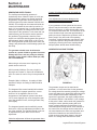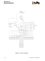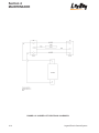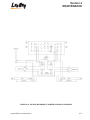
1
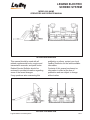
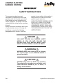
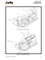
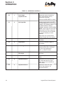
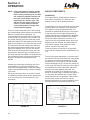
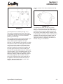
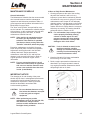
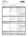
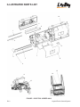
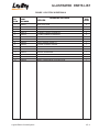
OPERATIONS AND
SERVICE MANUAL
LEGEND ELECTRIC SCREED SYSTEM
Manual No. 986622
Legend Electric Screed System
688 North Highway 16
Denver, North Carolina 28037
www.LeeBoy.com
LIMITED WARRANTY
POLICY AND PROCEDURES
WARRANTY
1. If a defect in material or workmanship is
found and the authorized dealer is notified
during the warranty period, LeeBoy will
repair or replace any part or component of
the unit or part that fails to conform to the
warranty during the warranty period.
2. The warranty date will begin upon the
completion of the warranty form by the initial
customer and will expire after twelve (12)
months have passed. The Warranty Card
should be filled out within (10) days of
delivery of the unit.
3. Engines are warranted by their
manufacturers and may have warranty
coverage that differs from that of LeeBoy.
4. Replacement parts furnished by LeeBoy are
covered for the remainder of the warranty
period applicable to the unit or component in
which such parts are installed.
5. LeeBoy has the right to repair any
component or part before replacing it with a
new part.
6. All new replacement parts purchased by a
LeeBoy dealer will carry a six (6) month
warranty. Remanufactured parts purchased
by a LeeBoy dealer will carry a ninety (90)
day warranty.
ITEMS NOT COVERED
LeeBoy is not responsible for the following:
1. Charges for travel time, mileage, or
overtime.
2. Charges related to transporting the product
to and from the place at which warranty
work is performed.
3. Airfreight charges related to transporting
repair parts to the place at which warranty
work is performed.
4. All used units or used parts of any kind.
5. Repairs due to normal wear and tear, or
brought about by abuse or lack of
maintenance of the equipment, except for
premature failures, conveyor chains,
polytrack pads, and track rails.
6. Attachments not manufactured or installed
by LeeBoy.
Legend Electric Screed System
7. Liability for incidental or consequential
damages of any type including, but not
limited to lost profits or expenses of acquiring
replacement equipment.
8. Miscellaneous charges.
LIMITATIONS
LeeBoy has no obligation under this warranty for:
1. Any defects caused by misuse,
misapplication, negligence, accident or failure
to maintain or use in accordance with the
most current operating instructions.
2. Unauthorized alterations.
3. Defects or failures caused by any
replacement parts or attachments not
manufactured by or approved by LeeBoy.
4. Failure to conduct normal maintenance and
operating service, including without limitation,
providing lubricants, coolant, fuel, tune-ups,
inspections or adjustments.
5. Unreasonable delay, as established by
LeeBoy, in making the applicable units or
parts available upon notification of a service
notice ordered by LeeBoy.
6. The warranty responsibility on all engines
rests with the respective manufacturer.
7. LeeBoy may have support agreements with
some engine manufacturers for warranty and
parts support.
OTHER WARRANTIES
THE FOREGOING WARRANTY IS EXCLUSIVE AND
IN LIEU OF ALL OTHER EXPRESSED STATUTORY
AND IMPLIED WARRANTIES APPLICABLE TO
UNITS ENGINES, OR PARTS WITHOUT LIMITATION,
ALL IMPLIED WARRANTIES OF MERCHANTABILITY
OR FITNESS FOR ANY PARTICULAR USE OR
PURPOSE. IN NO EVENT, WHETHER AS A RESULT
OF BREACH OF CONTRACT OR WARRANTY, OR
ALLEGED NEGLIGENCE OR LIABILITY WITHOUT
FAULT, SHALL LEEBOY BE LIABLE FOR SPECIAL,
INCIDENTAL OR CONSEQUENTIAL DAMAGES,
INCLUDING WITHOUT LIMITATION, LOSS OF
PROFIT OR REVENUE, COST OF CAPITAL, COST
OF SUBSTITUTED EQUIPMENT, FACILITIES OR
SERVICES DOWNTIME COSTS, LABOR COSTS OR
CLAIMS OF CUSTOMERS, PURCHASERS OR
LESSEES FOR SUCH DAMAGES.
LEGEND ELECTRIC
SCREED SYSTEM
USER'S REFERENCE GUIDE
DELIVERY DATE______________________________________
UNIT SERIAL NUMBER_________________________________
DEALER'S NAME AND ADDRESS
_____________________________________________________
_____________________________________________________
PHONE NUMBER_______________________________________
EQUIPMENT HOURS____________________________________
SERVICE MANAGER ____________________________________
688 North Highway 16 • Denver, North Carolina 28037 • www.LeeBoy.com • (704) 966-3300
Legend Electric Screed System
LEGEND ELECTRIC
SCREED SYSTEM
MODEL 000 NAME
OPERATORS AND SERVICE MANUAL
8515 SIDE AND REAR VIEW
This manual should be used with all
related supplemental books, engine and
transmission manuals, and parts books.
Related Service Bulletins should be
reviewed to provide information regarding
some of the recent changes.
If any questions arise concerning this
publication or others, contact your local
LeeBoy Distributor for the latest available
information.
Contents of this manual are based on
information in effect at the time of
publication and are subject to change
without notice.
8816 SIDE AND REAE VIEW
Legend Electric Screed System
FM.1
LEGEND ELECTRIC
SCREED SYSTEM
IMPORTANT
SAFETY INSTRUCTIONS
This manual provides important
information to familiarize you with safe
operating and maintenance procedures.
Even though you may be familiar with
similar equipment, you MUST read and
understand this manual before operating
this unit.
Safety is everyone's business and is one
of your primary concerns. Knowing the
guidelines covered in the following
paragraphs and in Section 1 will help
provide for your safety, for the safety of
those around you, and for the motor
grader's proper operation.
LOOK FOR THESE SYMBOLS WHICH
POINT OUT ITEMS OF EXTREME
IMPORTANCE TO YOU AND YOUR
COWORKERS SAFETY. READ AND
UNDERSTAND THOROUGHLY. HEED
THE WARNINGS AND FOLLOW THE
INSTRUCTIONS.
DANGER
YOU MUST FOLLOW ALL DANGER SAFETY
NOTES. IF YOU DO NOT FOLLOW THE
INSTRUCTIONS, YOUR MISTAKE MIGHT LIKELY
RESULT IN VERY SERIOUS INJURY OR DEATH.
WARNING
WARNING safety notes must ALSO be followed.
Your mistake might result in SERIOUS INJURY to
yourself or others.
CAUTION
CAUTION safety notes are ALSO very important.
They point out to you where your mistakes could
cause PHYSICAL HARM to you or others, or
damage to the machine.
FM.2
Legend Electric Screed System
LEGEND ELECTRIC
SCREED SYSTEM
SAFETY PRECAUTIONS
If your screed has been repainted, it is
extremely important that all the decals
referring to CAUTION, WARNING, and
DANGER be replaced in their proper
locations. The illustrations on this page will
aid you in determining the proper
locations; however, for additional help, you
should refer to the parts listing in the parts
section of this manual and note the
description column. Under this column, a
description of location is provided for each
decal. If you need more explicit
instructions, contact your dealer.
NOTE
It is the responsibility of the owner and
operator to make sure that all decals
are readable and located on motor
grader as designated by the
manufacturer.
8515 DECALS and DECAL LOCATIONS
Legend Electric Screed System
FM.3
LEGEND ELECTRIC
SCREED SYSTEM
8816 SCREED DECALS and DECAL LOCATIONS
PRE-START INSPECTION
Avoid steep hills if possible.
INSPECT machine. Have any malfunctioning,
broken or missing parts corrected or replaced
before using. Hydraulic hoses should be checked
daily for wear and leaks. Replace if damaged.
Always look before changing the direction of travel.
CHECK that all the instruction and safety labels are
in place and readable. These are as important as
any other equipment on the machine.
READ and FOLLOW all instruction decals.
WEAR OSHA required safety equipment when
running the screed.
Stopping Safety
Always park the paver on solid, level ground in Iow
range. If this is not possible, always park the paver
at a right angle to the slope. Lower screed when
parked.
Use proper flags, barriers and warning devices,
especially when parking in areas of traffic.
Maintenance Safety
Operating Safety
Always replace damaged or lost decals.
Always make sure no person or object is in the line
of travel before starting.
Work slowly in tight areas.
Work slowly in tight areas.
Never spray cleaning solvent or release agent on or
near screed while it is being heated.
Never spray cleaning solvent on or near screed
while it is being heated.
FM.4
Legend Electric Screed System
Section 1
INTRODUCTION
TABLE OF CONTENTS
Page
GENERAL INFORMATION . . . . . . . . . . . . . . . . . . . . . . . . . . . . . . . . . . . . . . . . . . . . . . . . . . . . . . . . . . .1.2
SPECIFICATIONS . . . . . . . . . . . . . . . . . . . . . . . . . . . . . . . . . . . . . . . . . . . . . . . . . . . . . . . . . . . . . . . . .1.2
CONTROLS AND OPERATING INSTRUCTIONS . . . . . . . . . . . . . . . . . . . . . . . . . . . . . . . . . . . . . . . . .1.2
MAINTENANCE PROCEDURES . . . . . . . . . . . . . . . . . . . . . . . . . . . . . . . . . . . . . . . . . . . . . . . . . . . . . .1.2
Legend Electric Screed System
1.1
Section 1
INTRODUCTION
GENERAL INFORMATION
This manual contains Specification information,
Controls and Operating Procedures, Maintenance
and Repair Procedures for the Legend Electric
Screed System.
SPECIFICATIONS
Refer to Section 2 - SPECIFICATIONS in this
manual for all major system specifications and for
typical torque value tables.
CONTROLS AND OPERATING
INSTRUCTIONS
Refer to Section 3 - OPERATION.
The operator of this equipment should READ,
UNDERSTAND, and FOLLOW the operating
instructions, Cautions, and Warnings provided in
the front of this manual and in the OPERATION
section.
1.2
WARNING: Do not attempt to operate the
Legend Electric Screed System
unless fully trained in the machine
operation, only authorized
personnel should operate the
Legend Electric Screed System. All
instructions provided in this
manual and on the machine decals
must be followed to prevent
damage to the equipment and/or
injury to operating personnel.
MAINTENANCE PROCEDURES
Refer to Section 4 - MAINTENANCE in this manual
for all maintenance and repair procedures.
CAUTION:
All maintenance instructions
provided in this manual should be
followed to insure safety of the
personnel performing the
maintenance and to prevent
damage to the machine.
Legend Electric Screed System
Section 2
SPECIFICATIONS
TABLE OF CONTENTS
Page
GENERAL INFORMATION . . . . . . . . . . . . . . . . . . . . . . . . . . . . . . . . . . . . . . . . . . . . . . . . . . . . . . . . . . 2.2
TABLE 2-1. DIMENSION SPECIFICATIONS . . . . . . . . . . . . . . . . . . . . . . . . . . . . . . . . . . . . . . . . . . . . 2.2
TABLE 2-2. SCREED. . . . . . . . . . . . . . . . . . . . . . . . . . . . . . . . . . . . . . . . . . . . . . . . . . . . . . . . . . . . . . . 2.3
TABLE 2-3. TORQUE SPECIFICATIONS FOR STANDARD INCH FASTENERS. . . . . . . . . . . . . . . . . 2.4
TABLE 2-4. TORQUE SPECIFICATIONS FOR METRIC FASTENERS . . . . . . . . . . . . . . . . . . . . . . . . 2.5
Legend Electric Screed System
2.1
Section 2
SPECIFICATIONS
GENERAL INFORMATION
The specifications provided in this section are applicable to the Legend Electric Screed System. Included in
this section are machine weights, dimensions, performance, and torque values for both metric and standard
inch fasteners.
TABLE 2-1. DIMENSION SPECIFICATIONS [See Figure 2-1]
8515 Legend Electric
8816 Legend Electric
Performance Specs.
Basic
8’ (2.44m)
8’ (2.44m)
Maximum
15’ (4.57m)
15’6” (4.72m)
Screed
Screed Plate
3/8” (9.5mm) AR400 Steel
1/2” (12.7mm) AR400 Steel
Main Screed
15” (.38m)
20” (.51m)
Extensions
7” (17.8cm)
12” (30.5cm)
Heating System
Electric
Electric
Extensions Length
3’6” (1.07m)
3’9” (1.14m)
Walkway Width
12” (30.5cm) W/Extension
12” (30.5cm) W/Extension
Dimensions
Weight
2,900 lbs. (1,315kg)
4,500 lbs. (2,041kg)
Overall Width (Transport)
8’6” (2.6m)
8’6” (2.6m)
FIGURE 2-1. OUTLINE DIMENSIONAL DRAWING
2.2
Legend Electric Screed System
Section 2
SPECIFICATIONS
TABLE 2-2. SCREED
ITEM
SPECIFICATION
Heat ....................................................Electric
Extensions ..........................................Two 45 inch hydraulically operated extensions
Vibration ............................................Two hydraulic vibrators producing 3400
vibrations per minute
Crown/Invert ........................................Adjustable, at least 2 inches of crown
and 1-1/2 inches of valley
Includes a level indicator
Legend Electric Screed System
2.3
Section 2
SPECIFICATIONS
TABLE 2-3. TORQUE SPECIFICATIONS FOR STANDARD INCH FASTENERS
WARNING: The following Table lists torque values for standard hardware and are intended as a
guide for average application involving typical stresses and machined surfaces. Values
are based on physical limitations of clean, plated and lubricated hardware. In all cases,
when an individual torque value is specified, it should be followed instead of values
given in this table.
CAUTION:
Replace original equipment with hardware of equal grade.
CAPSCREWS: SAE GRADE 5
SIZE
1/4
5/16
3/8
7/16
1/2
9/16
5/8
3/4
7/8
1
1-1/8
1-1/4
1-3/8
1-1/2
2.4
THREAD
TORQUE FT. LBS.
TORQUE N•m
CAPSCREWS: SAE GRADE 8
TORQUE FT. LBS.
TORQUE N•m
Dry
Lubed
Dry
Lubed
Dry
Lubed
Dry
Lubed
20 UNC
8
6
11
9
12
9
16
12
28 UNF
10
7
13
10
14
10
19
14
18 UNC
17
13
24
18
25
18
33
25
24 UNF
19
14
26
20
27
20
37
28
16 UNC
31
23
42
31
44
33
59
44
24 UNF
35
26
47
36
49
37
67
50
14 UNC
49
37
67
50
70
52
95
71
20 UNF
55
41
75
56
78
58
105
79
13 UNC
75
57
100
77
105
80
145
110
20 UNF
85
64
115
86
120
90
165
120
12 UNC
110
82
145
110
155
115
210
155
18 UNF
120
91
165
125
170
130
230
175
11 UNC
150
115
205
155
210
160
285
215
18 UNF
170
130
230
175
240
180
325
245
10 UNC
265
200
360
270
375
280
510
380
16 UNF
295
225
405
300
420
315
570
425
9 UNC
430
320
580
435
605
455
820
615
14 UNF
475
355
640
480
670
500
905
680
8 UNC
645
485
875
655
910
680
1230
925
14 NF
720
540
980
735
1020
765
1380
1040
7 UNC
795
595
1080
805
1290
965
1750
1310
12 UNF
890
670
1210
905
1440
1080
1960
1470
7 UNC
1120
840
1520
1140
1820
1360
2460
1850
12 UNF
1240
930
1680
1260
2010
1500
2730
2050
6 UNC
1470
1100
1990
1490
2380
1780
3230
2420
12 UNF
1670
1250
2270
1700
2710
2040
3680
2760
6 UNC
1950
1460
2640
1980
3160
2370
4290
3210
12 UNF
2190
1650
2970
2230
3560
2670
4820
3620
Legend Electric Screed System
Section 2
SPECIFICATIONS
TABLE 2-4. TORQUE SPECIFICATIONS FOR METRIC FASTENERS
WARNING: The following Table lists torque values for standard hardware and are intended as a
guide for average application involving typical stresses and machined surfaces. Values
are based on physical limitations of clean, plated and lubricated hardware. In all cases,
when an individual torque value is specified, it should be followed instead of values
given in this table.
CAUTION:
Replace original equipment with hardware of equal grade.
NOMINAL SIZE
& PITCH
CLASS 8.8
[GRADE 5 EQUIVALENT]
TORQUE FT. LBS.
TORQUE N•m
CLASS 10.9
[GRADE 8 EQUIVALENT]
TORQUE FT. LBS.
TORQUE N•m
Dry
Lubed
Dry
Lubed
Dry
Lubed
Dry
Lubed
M4 x 0.7
2.27
1.70
3.07
2.30
2.27
2.31
4.17
3.13
M5 x 0.8
4.58
3.43
6.20
4.65
6.22
4.67
8.43
6.33
M6 x 1
7.75
5.83
10.5
7.90
10.60
7.97
14.3
10.8
M8 x 1.25
18.89
14.17
25.6
19.2
18.95
19.26
34.8
26.1
M10 x 1.25
39.11
29.52
53.0
40.1
53.87
40.59
73.0
55.0
M12 x 1.75
64.94
48.71
88.0
66.0
88.56
66.42
120.0
90.0
M14 x 2
103.32
77.49
140.0
105.0
140.22
107.01
190.0
145.0
M16 x 2
162.36
121.77
220.0
165.0
221.40
166.05
300.0
225.0
M20 x 2.5
317.34
236.16
430.0
320.0
428.04
321.03
580.0
435.0
M24 x 3
516.12
409.59
740.0
555.0
754.38
557.19
1010.0
755.0
M27 x 3
797.04
597.78
1080.0
810.0
1084.86
811.80
1470.0
1100.0
M30 x 3.5
1084.86
811.80
1470.0
1100.0
1476.00
1107.00
2000.0
1500.0
Legend Electric Screed System
2.5
Section 3
OPERATION
TABLE OF CONTENTS
Page
GENERAL INFORMATION . . . . . . . . . . . . . . . . . . . . . . . . . . . . . . . . . . . . . . . . . . . . . . . . . . . . . . . . . . .3.2
OPERATING CONTROLS . . . . . . . . . . . . . . . . . . . . . . . . . . . . . . . . . . . . . . . . . . . . . . . . . . . . . . . . . . .3.2
OPERATION . . . . . . . . . . . . . . . . . . . . . . . . . . . . . . . . . . . . . . . . . . . . . . . . . . . . . . . . . . . . . . . . . . . . . .3.5
SAFETY . . . . . . . . . . . . . . . . . . . . . . . . . . . . . . . . . . . . . . . . . . . . . . . . . . . . . . . . . . . . . . . . . . . . . . .3.5
Operating Safety . . . . . . . . . . . . . . . . . . . . . . . . . . . . . . . . . . . . . . . . . . . . . . . . . . . . . . . . . . . . .3.5
Stopping Safety . . . . . . . . . . . . . . . . . . . . . . . . . . . . . . . . . . . . . . . . . . . . . . . . . . . . . . . . . . . . . .3.5
Maintenance Safety . . . . . . . . . . . . . . . . . . . . . . . . . . . . . . . . . . . . . . . . . . . . . . . . . . . . . . . . . . .3.5
PRE-START INSPECTION . . . . . . . . . . . . . . . . . . . . . . . . . . . . . . . . . . . . . . . . . . . . . . . . . . . . . . . .3.5
OPERATING LEGEND ELECTRIC SCREED SYSTEM . . . . . . . . . . . . . . . . . . . . . . . . . . . . . . . . . .3.5
MAJOR COMPONENTS . . . . . . . . . . . . . . . . . . . . . . . . . . . . . . . . . . . . . . . . . . . . . . . . . . . . . . . . . . . .3.6
GENERATOR . . . . . . . . . . . . . . . . . . . . . . . . . . . . . . . . . . . . . . . . . . . . . . . . . . . . . . . . . . . . . . . . . . .3.6
BREAKER . . . . . . . . . . . . . . . . . . . . . . . . . . . . . . . . . . . . . . . . . . . . . . . . . . . . . . . . . . . . . . . . . . . . .3.7
HEATING CONTROL OR DISTRIBUTION/CONTROL BOX . . . . . . . . . . . . . . . . . . . . . . . . . . . . . . .3.7
ELEMENT CONNECTIONS . . . . . . . . . . . . . . . . . . . . . . . . . . . . . . . . . . . . . . . . . . . . . . . . . . . . . . .3.8
HEATING ELEMENT . . . . . . . . . . . . . . . . . . . . . . . . . . . . . . . . . . . . . . . . . . . . . . . . . . . . . . . . . . . .3.10
Legend Electric Screed System
3.1
Section 3
OPERATION
GENERAL INFORMATION
OPERATING CONTROLS
This section provides the Operating Instructions for
the Legend Electric Screed System.
Operating controls for the Legend Electric Screed
System are shown in Figure 3-1 and listed in Table
3-1.
It is important to read, understand, and follow all
"Precautions Operating Instructions and Warnings"
written in this manual before starting or operating
the machine.
DANGER:
Failure to observe the “Operating
Precautions and Warning
Instructions” provided in this
manual can cause serious injury or
death. Only authorized personnel,
who are fully trained in the
machine operation, can operate the
Legend Electric Screed System.
WARNING: Do not start or operate the Legend
Electric Screed System before
reading, understanding, and
following all information given in
this section and shown on the
machine. The operators must read
and understand the function of all
controls, indicators, and gauges
before starting the engine. Serious
injury or death can result if these
procedures are not followed.
This machine should be kept in good mechanical
condition at all times.
WARNING: Do not operate a machine needing
repairs. Put an information tag on
the instrument panel that says, “DO
NOT OPERATE”. Remove the key
from the ignition switch. Repair all
damage at once. Minor damage
can result in major system failures.
3.2
Legend Electric Screed System
Section 3
OPERATION
FIGURE 3-1. OPERATING CONTROLS
Legend Electric Screed System
3.3
Section 3
OPERATION
TABLE 3-1. OPERATING CONTROLS
FIG. REF
3-1
ITEM NO.
1
CONTROL NAME
TYPE
FUNCTION
Adjusts the height of material at
Sonic Auger Sensor (Item 5)
mounted on End Gate.
Sonic Auger
Adjustment Left
Controls AUGER SPEED in manual.
3-1
2
Contains toggle switches for LEFT
EXTENSION IN/OUT, SLOPE RAISE/
LOWER, LEFT AUGER ON/OFF, and
AUGER MATERIAL HEIGHT
MIN/MAX, MANUAL AUGER SPEED.
Left Auger Box
NOTE: Auger toggle should be left in
ON position at all times. Auger and
screed extensions can be operated
by a person standing on Lower
walkway.
Right Auger box is identical and
located on right side of the machine.
3.4
3-1
3
Depth Screw
This control sets the depth of the
End Gate.
3-1
4
Flight Screw
This lever controls the depth of
the asphalt.
3-1
5
Sonic Auger Sensor
Used for adjusting the height of
material at End Gate. Connected
to Sonic Auger Adjustment
(Item 1). Keep End Clean.
3-1
6
Speed and
Pile Height
3-1
7
Tilt Screw
Used to adjust the tilt on End
Gate.
3-1
8
Adjustment Screw
Adjusts the front of the extension
to provide the best mat. Up or
down and can level extension at
wide widths.
3-1
9
Adjustment Screw
Adjusts the other end of the
front of the extension. Tilt
Rougher/Smoother.
Potentiometer
Adjust thickness of material in
End Gate.
Legend Electric Screed System
Section 3
OPERATION
OPERATION
SAFETY
Operating Safety
ALWAYS make sure no person or object is in the
line of travel before starting.
WORK slowly in tight areas.
NEVER spray cleaning solvent on or near screed
while it is being heated.
3-2). Once the heating function has been enabled,
the distribution/control box will apply electrical
power to the heating elements and the heating
cycle will begin. The heating cycle is timed to
optimize the heat generated at the screed plates.
Once the timed cycle finishes, the heat will cycle
off, and will not re-start unless the operator restarts the cycle by pressing the "start heat" function
on the control box.
AVOID steep hills if possible.
ALWAYS look before changing the direction of
travel.
Stopping Safety
ALWAYS park the paver on solid, level ground in
Iow range. If this is not possible, always park the
paver at a right angle to the slope. Lower screed
when parked.
USE proper flags, barriers and warning devices,
especially when parking in areas of traffic.
FIGURE 3-2
Maintenance Safety
ALWAYS replace damaged or lost decals.
WORK slowly in tight areas.
NEVER spray cleaning solvent or release agent on
or near screed while it is being heated.
PRE-START INSPECTION
Inspect machine. Have any malfunctioning, broken
or missing parts corrected or replaced before
using. Hydraulic hoses should be checked daily for
wear and leaks. Replace if damaged.
Check that all the instruction and safety labels are
in place and readable. These are as important as
any other equipment on the machine.
Read and Follow all instruction decals.
Wear OSHA required safety equipment when
running the screed.
OPERATING LEGEND ELECTRIC SCREED
SYSTEM
The Legend electrically heated screed system is
very easy to operate, and requires very little
maintenance. The system consists of a
hydraulically driven generator mounted in the
paver, which feeds power to a distribution/control
box mounted on the screed. The control box is
where you will select the
heating function before you begin to pave (See Fig.
Legend Electric Screed System
To operate the screed heating system, start the
paver and bring the engine to normal operating
temperature as outlined in the paver manual. Once
the paver is at operating temperature, set the
throttle on the paver to full engine RPM.
NOTE: Throttle positions less than full will still
produce screed heat, but at a
drastically reduced rate and
temperature.
On the screed heat control box, turn the power
switch (Figure 3-2, Item 1) to the "ON" position.
Now press the "Start Heat" (2) button. The heating
cycle will begin, and the "Heat On" (3) light will
illuminate. The "Heat On" (3) light will stay on as
long as the screed heat is operating. The factory
time setting for the heating cycle is approximately
30 minutes. This should be sufficient in most
circumstances to generate sufficient heat for the
paving process to begin without screed heat
problems. Once the heating cycle is complete, the
"Heat On" (3) light will go out, and the elements will
no longer heat the screed plates. The temperature
that the screed plates reach will depend on the
outside ambient temperature of the day, or morning
that the heat is operated. If, after the heat cycle is
run one time, and the screed plates still require a
higher temperature, the operator only has to restart the system by pressing the "Start Heat" (2)
button again. The system will run for the set time
once more.
3.5
Section 3
OPERATION
NOTE: If the heat system is running, and the
operator presses the "Start Heat" (2)
button during a heating cycle, the heat
will continue to operate normally, and
the timer circuit will be re-set to the
beginning of it's set time cycle. This
will not hurt the system, and may be
useful on cooler days to make the
screed heat system run longer than
normal without stopping.
There are certain things that can be done to help
the screed heating system operate most efficiently.
When the screed heat is in operation, it is
recommended that the screed not be set directly
on the ground. It is also better if the screed is not
fully raised, allowing more wind under the screed
plate while heating. The best position for the screed
plate is to be raised 1 to 2 inches off of the ground.
This will provide the best results when heating. If
the ambient temperatures outside where you are
paving are relatively warm, you may not need to
have the screed in this position to heat, but it will
help when the winds are high, or the day is cool.
Be certain that the paver RPM is at full throttle. You
may find that the faster you operate the engine of
the paver the better the heating system will
operate.
Another way to decrease the heating time of the
screed plates is to set the screed directly on a
fresh mat of hot asphalt while running the heating
system. This should drastically reduce the heating
cycle times.
During normal usage, there are no other controls
for operating the heat system. All the operator has
to do is run the paver, turn the system on, and
select heat.
FIGURE 3-3
3.6
MAJOR COMPONENTS
GENERATOR
The Legend Electric Screed System consists of
three major components. The generator, and
heating controls, and the heating elements.
The generator is the first component. On your 8500
and 8515 paver, the generator is mounted under
the hopper floor near the right hand track. The
generator is hydraulically driven by the first section
of the rear pump on the engine pump stack. All
LeeBoy generators are equipped with a integrated
generator speed control manifold. This manifold
should not require adjustment, but if there is a
need to fine tune the generator speed, there is an
adjustment on the manifold. This adjustment will
only effect the speed of the generator a small
amount, and is for fine tuning only.
The picture shows an example of the generator
motor with the integrated control manifold (See Fig.
3-3).
The fine tune speed adjustment (1) is on the top of
the manifold. The two ports facing you in the picture
are pressure (2) and the discharge port (3). The
pressure line is on the right (2), into the manifold,
and the discharge line (3) is on the left, coming out
of the motor. The fitting (4) coming out of the top of
the manifold is the motor case drain, and is tied
directly to the lower hydraulic belly tank. The
generator is provided oil for operation by a gear
pump on the paver engine. The faster the engine is
run, the faster the generator will run also. When
testing the speed of your generator, make certain
that the paver engine rpm is at full, and the
hydraulic temperature is at normal operating levels.
See Maintenance for generator speed tuning.
FIGURE 3-4
Legend Electric Screed System
Section 3
OPERATION
The entire generator is shown here (See Fig. 3-4).
Note the electrical cord (1) coming out of the case
of the generator at the far left. This is the cable that
runs to the rear of your paver that supplies power
to the screed. This cable should be inspected
regularly to ensure that no damage has occurred to
the cable during normal operation. Chafing, cuts,
breaks, etc.
HEATING CONTROL OR
DISTRIBUTION/CONTROL BOX
Next in your system is the heating control, or
distribution/control box (See Fig. 3-7). This box is
mounted on the screed, and is easily accessible to
the screed operator when a heating cycle is
required.
NOTE: If damage is seen in the power cable,
the unit should not be operated until a
new cable is installed.
BREAKER
Figure 3-4 also shows the location of the main
output breaker (2) in your generator. All output
power from the generator is lost when this breaker
is in the “tripped” or “off” position.
NOTE: If, when your screed heat system is
turned on, you have no heat on any
screed, this breaker should be
checked. If, after resetting the breaker,
it will not stay in the “on” position, a
screed wiring fault should be assumed.
See Maintenance, Section 4.
FIGURE 3-6
FIGURE 3-7
The control box has a power switch (1), a "Heat
On" button (2), and a heat cycle indicator light (3).
Under normal operation, the operator will only turn
the power switch (1) to the "Power" position, and
depress the "Heat On" button (2).
The bottom of the control box contains the system
element breakers, and the 6 main outputs for the
screed heating elements (See Fig. 3-8). Since the
heating elements are powered by 220 VAC to
240VAC, each element has two breakers. There is
one breaker for each leg of each element. Also
shown is one of the two pin plugs that supplies
power to the screed elements. There are a total of
six plugs.
The rear of the generator is shown here (See Fig.
3-6). You can see the power cable (1) coming into
the generator case at the top right. Just below the
generator case is the voltage capacitor. The
capacitor controls the output voltage of the
generator, and may need to be changed if no
voltage is generated by the set. See Maintenance
for generator voltage testing.
The main output of the generator is located in the
lower left of the picture. You will see two main wires
attached to the generator, a black wire (2), and a
white wire (3). These are referred in other sections
of this manual as L1 and L2. The other two wires
(4) at the far left of the terminal block are generator
winding wires, and should not need to be serviced
under normal circumstances.
Legend Electric Screed System
3.7
Section 3
OPERATION
ELEMENT CONNECTIONS
Any element lead can be plugged into any supply
plug under the heating control control/distribution
box. All six plugs are equally rated.
NOTE: All control boxes are manufactured the
same to fit all screed and paver
combinations. If your screed does not
have enough element wires to fill all
the plugs on the bottom of the control
box, it may be normal. Any plugs that
are not filled should be capped with
appropriate plug terminator.
this manual, and you will note the following
connections are made.
Each element output from the bottom of the box
consists of two wires. One wire will connect to the
L1 circuit, and the other wire will connect to the L2
circuit. The L1 circuit is the left bank of element
breakers. Each breaker has two terminals. One
terminal is connected to the main input, and the
other terminal is connected directly to an element
output wire. The L2 circuit is the right bank of
element breakers. This bank is wired slightly
different, in that each leg not only goes from the
main L2 power lead through a breaker, but each
leg then goes through one of the six contacts on
the element relays. It is these relays that "make" or
"break" the circuit to each element to start or stop
the heating cycles.
An element relay is shown here (See Fig. 3-10).
There are three relays in the control box. Each
relay has two separate sets of contacts operated by
one coil.
FIGURE 3-8
This picture shows the contents of the control box
before the wiring is completed (See Fig. 3-9).
The coil contacts on the relay shown are at the top
and bottom of the right hand side of the relay. One
set of contacts are the two terminals (1) at the top
left of the relay, and the other set of contacts (2)
are at the bottom left of the relay shown.
FIGURE 3-9
When the coil is energized, both sets of contacts
will close. All the relays used are "normally open"
See Maintenance for testing element relays.
The control box consists of three major types of
components. The system timer (1) is located in the
upper left hand corner of the box. The element
relays (2) are located in the upper right hand
corner of the box, and the element breakers (3) are
located in the lower surface of the box. The other
block in the center is used as a wire junction block
only. Refer to the wiring schematic at the end of
3.8
Legend Electric Screed System
Section 3
OPERATION
Here is a picture of an element breaker (See Fig.
3-12).
FIGURE 3-11
A heat system timer is shown (See Fig. 3-11).
There are six terminals on the timer. The top two
left terminals are the main 12vdc input terminals for
the timer. The ground (1) is on the left and the
power (2) is on the right.
The top right terminal is the common terminal (3) to
the internal timer relay that controls the heat
system. When power is applied to the input
terminal, it is also jumped to the common (or COM)
terminal on the timer. The lower right two terminals
on the timer are the outputs of the internal timer
relay. The left of these two is the normally closed
terminal (4), which is not used in this system, and
the lower right terminal (5) is the normally open
terminal. The normally open terminal is used as our
output terminal to "turn" the heating system on. The
lower left hand terminal (6) is the "initiate" contact.
When the "Heat On" button is depressed, 12vdc is
momentarily applied to this terminal to start the
timer cycle. During the timer cycle, power will not
be applied to this terminal unless the "Heat On"
button is depressed again. Keep in mind, if this
happens, the timer will re-start.
Legend Electric Screed System
FIGURE 3-12
The breakers are wired into each leg of each
element. If an element has a fault, either in the
wiring, or in the element itself, the breaker will trip
and power will no longer be applied to that leg of
the element. The breakers can be manually re-set
by depressing the trip button back in when they are
extended. If by depressing the breaker re-set, the
breaker will not re-set, there may be a need to
replace the breaker, or diagnose the element, or
element wiring, it is connected to.
3.9
Section 3
OPERATION
HEATING ELEMENT
Next in your system are the screed heating
elements themselves. Each element is sized to fit
properly in your screed, and provide sufficient
power to heat your screed plate to a temperature
that mix will not drag or stick to the lower surface of
the screed plate.
elements. Usually this layer should not be more than
1/16" thick before the element is installed.
FIGURE 3-15
FIGURE 3-13
An element assembly consists of four main
components. The element (1), the wire protector
adapter (2), the wire protector (3), and the two pin
wire plug (4) at the end of the element protector
(See Fig. 3-13).
Each element (1) used has a thin strip of insulation
(2) over it to keep the heat of the element from
escaping. A support bar (3) is then laid over the
element, and a shield (4) protects the element
assembly (See Fig. 3-14). Each element is
clamped down to the screed plate so as to provide
a positive and efficient connection between the
element and the screed plate.To help ensure a
good transfer of heat from the element to the
screed plate, a heat transfer compound is used.
This compound should be applied sparingly to the
lower surface of the element with a putty knife or
FIGURE 3-14
other similar tool before the element is installed in
the screed (See Fig. 3-15). A thin layer of heat
transfer compound is all that is needed. Only enough
to be certain that there are no air gaps under the
3.10
Apply the heat transfer compound as previously
shown. Remember, a thin layer to ensure contact is
all that is needed. If you use too much compound,
the element will not be able to be clamped to the
screed close enough, and a loss of heating
potential will occur.
FIGURE 3-16
A typical element clamp assembly is shown (See
Fig. 3-16). The clamp setup may vary slightly
depending on your screed size, or whether you are
working on the extension or main screed plates.
The principle is the same with all of the clamps.
Enough pressure should be applied to the element
assembly to sufficiently hold the element tight
against the screed plate surface. All clamp setups
are lockable with a jam nut on the adjustment
screw. After tightening the clamping stud, lock the
clamp by tightening the stud jam nut. To remove an
element, loosen all the clamping studs over the
element, and then the element can be removed
from the frame through the access provided at the
outer end of the screed. The extension elements
are accessed by removing the top cover from the
extension screed plate.
Legend Electric Screed System
Section 4
MAINTENANCE
TABLE OF CONTENTS
Page
GENERAL INFORMATION . . . . . . . . . . . . . . . . . . . . . . . . . . . . . . . . . . . . . . . . . . . . . . . . . . . . . . . . . . .4.2
ROUTINE MAINTENANCE . . . . . . . . . . . . . . . . . . . . . . . . . . . . . . . . . . . . . . . . . . . . . . . . . . . . . . . . . .4.2
GENERAL INFORMATION . . . . . . . . . . . . . . . . . . . . . . . . . . . . . . . . . . . . . . . . . . . . . . . . . . . . . . . .4.2
MACHINE LUBRICATION . . . . . . . . . . . . . . . . . . . . . . . . . . . . . . . . . . . . . . . . . . . . . . . . . . . . . . . . .4.2
MAINTENANCE SCHEDULE . . . . . . . . . . . . . . . . . . . . . . . . . . . . . . . . . . . . . . . . . . . . . . . . . . . . . .4.5
General Information . . . . . . . . . . . . . . . . . . . . . . . . . . . . . . . . . . . . . . . . . . . . . . . . . . . . . . . . . . .4.5
10 Hour or Daily Routine Maintenance . . . . . . . . . . . . . . . . . . . . . . . . . . . . . . . . . . . . . . . . . . . .4.5
After The First 50 Hours and Weekly Routine Maintenance . . . . . . . . . . . . . . . . . . . . . . . . . . . .4.6
SCREED EXTENSION TOP GUIDE ADJUSTMENT . . . . . . . . . . . . . . . . . . . . . . . . . . . . . . . . . . . . . . .4.6
REPLACING SCREED EXTENSION WEARPLATES . . . . . . . . . . . . . . . . . . . . . . . . . . . . . . . . . . . . . .4.7
Removal . . . . . . . . . . . . . . . . . . . . . . . . . . . . . . . . . . . . . . . . . . . . . . . . . . . . . . . . . . . . . . . . . . . . . . .4.7
Installation . . . . . . . . . . . . . . . . . . . . . . . . . . . . . . . . . . . . . . . . . . . . . . . . . . . . . . . . . . . . . . . . . . . . .4.7
REPLACING SCREED MAIN WEARPLATES . . . . . . . . . . . . . . . . . . . . . . . . . . . . . . . . . . . . . . . . . . . .4.7
Removal . . . . . . . . . . . . . . . . . . . . . . . . . . . . . . . . . . . . . . . . . . . . . . . . . . . . . . . . . . . . . . . . . . . . . . .4.7
Installation . . . . . . . . . . . . . . . . . . . . . . . . . . . . . . . . . . . . . . . . . . . . . . . . . . . . . . . . . . . . . . . . . . . . .4.7
GENERATOR SPEED TUNING . . . . . . . . . . . . . . . . . . . . . . . . . . . . . . . . . . . . . . . . . . . . . . . . . . . . . . .4.8
GENERATOR VOLTAGE TESTING . . . . . . . . . . . . . . . . . . . . . . . . . . . . . . . . . . . . . . . . . . . . . . . . . . . .4.8
TESTING ELEMENT RELAYS . . . . . . . . . . . . . . . . . . . . . . . . . . . . . . . . . . . . . . . . . . . . . . . . . . . . . . . .4.9
ELEMENT RESISTANCE TESTING . . . . . . . . . . . . . . . . . . . . . . . . . . . . . . . . . . . . . . . . . . . . . . . . . . . .4.9
TESTING THE CONTROL TIMER . . . . . . . . . . . . . . . . . . . . . . . . . . . . . . . . . . . . . . . . . . . . . . . . . . . .4.10
SCHEMATICS . . . . . . . . . . . . . . . . . . . . . . . . . . . . . . . . . . . . . . . . . . . . . . . . . . . . . . . . . . . . . . . . . . . .4.12
TROUBLESHOOTING . . . . . . . . . . . . . . . . . . . . . . . . . . . . . . . . . . . . . . . . . . . . . . . . . . . . . . . . . . . . .4.16
Legend Electric Screed System
4.1
Section 4
MAINTENANCE
GENERAL INFORMATION
This section gives the necessary procedures for
routine and general maintenance on the Legend
Electric Screed System.
Follow all the Maintenance Schedules and
Maintenance Procedures to maintain the machine
in top operating order.
ROUTINE MAINTENANCE
GENERAL INFORMATION
MAINTENANCE must be a planned program that
includes periodic machine inspection and
lubrication procedures.
The MAINTENANCE program must be done,
based on the machine "Operating Hours", recorded
on the hourmeter, or based on the "Periodic
Schedule'', which is done at time intervals of
weekly, monthly, or yearly.
MACHINE LUBRICATION
Proper lubrication is necessary to maintain the
machine at top efficiency. Refer to the lubrication
information in Table 4-1 Lubrication Chart. All
lubrication points are shown in Figure 4-1.
4.2
Legend Electric Screed System
Section 4
MAINTENANCE
FIGURE 4-1. LUBRICATION POINTS
Legend Electric Screed System
4.3
Section 4
MAINTENANCE
TABLE 4-1. LUBRICATION CHART
ITEM NO.
TYPE LUB
DESCRIPTION AND LOCATION
INTERVAL
1
B
SCREED EXTENSIONS, left and right (clean surface)
Daily
2
B
SPRAY ANY PART OF MACHINE THAT CONTACTS
ASPHALT
Daily
3
A
SCREED CROWN, on chain and turnbuckles
Weekly
4
A
DEPTH SCREW (grease first in lock position, unlock
and turn 180° and grease)
Weekly
5
A
MAIN FLIGHT SCREWS BALL SOCKET & NUT
Weekly
6
A
ALL SCREWS ON EXTENSION AND BEARING
Weekly
7
A
TUBES AT CHROME ROD EXTENSIONS
Weekly
8
A
TILT SCREWS
Weekly
9
A
SCREED PIVOT
Weekly
10
A
SLOPE CYLINDER PIVOT
Weekly
LEGEND
4.4
A
GREASE WITH SHELL AVANIA EP GREASE 2 OR EQUIVALENT
B
SPRAY WITH AN APPROVED RELEASE AGENT
Legend Electric Screed System
Section 4
MAINTENANCE
MAINTENANCE SCHEDULE
General Information
The Maintenance Schedule lists the recommended
time intervals between machine maintenance
inspections and lubrication procedures. Table 4-1
gives inspection and lubrication information for the
Model 8816 Conveyor Paver.
The "Hour" and "Periodic" time periods list most
service intervals. The maintenance schedule begins
with ten hours, or daily, maintenance intervals and
continues through the 1,000 hours, or annual,
maintenance schedule intervals.
NOTE: If the machine is operated more than
ten hours per day, follow the "Hour"
schedule. If the machine is operated
less than ten hours per day, follow the
"Periodic" schedules, where they apply.
Preventive maintenance on the 8816 Conveyor
Paver will provide years of trouble-free operation.
Adjustment can be performed in the field with
ordinary hand tools. Engine preventative
maintenance, other than oil, air, and fuel filter
changes is not covered in this section. Refer to
engine operator's manual for engine service
information.
NOTE: For your convenience there is an oil
drain hose located inside of right hand
side cover on machine. Remove small
access cover and stick hose thru hole
in side. (Later Models).
10 Hour or Daily Routine Maintenance
1. Cleaning the paver at the end of the working
day while the machine is still hot is very
important. A paver that is continuously left with
mix stuffed in every corner is going to increase
maintenance costs. Scrape off mix and spray
cleaning solvent or release agent on the screed
plate, hopper, etc., any place that has come in
contact with the mix. Spray down the conveyors
while they are running. All cleaning should be
performed while the machine is hot.
NOTE: For cold weather, keep conveyor flight
chains properly oiled with cleaning
solvent or release agent. This will
prevent conveyor bars from sticking.
Neglect could result in conveyor bar
damage/or drive chain failure.
CAUTION:
If mix is allowed to remain in the
machine overnight, possible
damage can result on start-up the
next day. Poor housekeeping will
increase maintenance costs.
2. Keep the fuel tank full to keep condensation
from forming. Fill at end of day.
3. Perform engine preventative maintenance as
described in your engine operator's manual.
Any engine preventative maintenance should
always begin with an oil check.
IMPORTANT NOTICE!
The changing of oil and cleaning of the paver
should only be done in a designated area that can
contain the oil and chemicals involved in any
maintenance requirement. These by-products
should be discarded In accordance with
environmental regulations.
CAUTION:
Do not substitute fasteners of any
kind unless the fasteners are equal
in size and grade as original
equipment.
NOTE: When performing any routine
maintenance such as 50, 100, 250, 500,
and 1000 hours, always include
previous routine maintenance hours to
the higher hourly schedule.
Legend Electric Screed System
FIGURE 4-2. EXTENSION SLIDE LUBRICATION
4.5
Section 4
MAINTENANCE
After The First 50 Hour and Weekly Routine
Maintenance
SCREED EXTENSION TOP GUIDE
ADJUSTMENT
1. For both sides of the screed, lubricate all
grease fittings on the flight screw, the fitting on
the depth screw, and the fittings on the flange
bearings located on top of the extension screed
(see Figure 4-3). Grease nuts on extension
screws.
1. Close the left and right extensions to their fully
retracted positions.
2. Locate the five ½" bolts that hold the upper
slide guide rails on the rear of the screed
frames for each side.
3. Loosen the five ½" bolts that hold the upper
slide guide rails.
4. Using a blunt punch and a hammer, carefully
tap the upper slide guide rail down. Access the
upper slide guide rails through the small
openings in the upper cover near the front of
the main screed frame. Start at the outside of
the machine, and work your way in to the
center. Tighten each of the five ½" bolts, one at
a time, as you work your way to the center.
5. When the upper slide guide rail is tight, finish
tightening the five bolts per side to 75 ft. lbs.
(100 N.m.).
6. Run the extensions out fully and grease the
slide track rails.
NOTE: The slide tracks should be greased
daily to help prevent excessive wear.
FIGURE 4-3. SCREED ASSOCIATED LUBRICATION POINT LOCATIONS
4.6
Legend Electric Screed System
Section 4
MAINTENANCE
REPLACING SCREED EXTENSION
WEAR-PLATES
REPLACING SCREED MAIN WEARPLATES
Removal
Removal
1. Run extension out fully.
2. Remove endgate by disconnecting tilt screw
and loosen the 7/8" jam nut.
3. Remove nut. Endgate will drop forward out of
slot and slide off of stud.
4. Remove bolts out of lower adjustment screws
on top of wearplate.
5. Locate and unplug the element power wire.
Make certain the wire running into the
extension screed is loose and will drop away
when the screed plate is removed with
interference. Closely inspect the plugs, pins,
and wires for damage. Replace if needed.
6. Lower screed to ground and pull front pivot pin
out.
7. Lift screed and wearplate should be
disconnected.
Installation
1. Clean all areas where new wearplate will be
attached.
2. Place new wearplate in position with floor jack
or by lowering screed to floor and slide pivot
pin in.
3. Reconnect the element power wire and retie
the power cable to the attachment point
provided.
NOTE: Do not tie the power cable so that it is
tight. A small amount of slack in the
cable where it enters the protective
hose fitting is required.
4. Attach adjustment screws to new wearplate.
5. Place endgate back on.
6. Adjust 7/8" nut so that endgate will move up
and down freely, then lock in place with jam
nut.
7. Connect tilt screw.
1. Remove walkboards.
2. Remove screed lids.
NOTE: Once walkboards are removed lids will
slide out.
3. Remove or torch the 20 bolts holding wearplate
to screed frame.
4. Under the heating control/distribution box,
locate the element attachment plugs. Remove
the protective cover, and unplug the main
screed elements so that the main element
power wires can be lowered with the wear
plate.
5. Before raising screed off of wearplate, clamp
center of crown gussets so that screed frame
stays flat.
6. Raise screed off of wearplate.
Installation
1. Clean screed frame.
2. Set screed frame down on to new wearplate
letting cylinders carry most of weight. This will
let plate be moved for alignment of bolts.
3. Place 5 bolts in front left side first.
4. Rotate crown in and out so that five bolts in
right side line up.
NOTE: May need to clamp or pry around to
line up.
5. Once these bolts are in place, bolt rear of plate
up to frame assembly.
6. Once bolts are started, lift screed and set on
three 2" x 4" boards to hold flat. Place one
board at each end and one in the center.
7. Let screed all the way down and torque bolts
from center out, 2 on left side then 2 on right
side until all bolts are torque to 50 ft. lbs.
(67 N.m).
8. Install screed lids and walkboards.
9. Reconnect all element wires that were
unplugged. Closely inspect all plugs, pins, and
wires for damage. Replace if needed.
Legend Electric Screed System
4.7
Section 4
MAINTENANCE
GENERATOR SPEED TUNING
The LeeBoy screed heating generator is
hydraulically driven. When the paver is at full rpm,
and the hydraulic system is at normal operating
temperature, the generator should operate at a
sufficient speed to produce between 220VAC and
240VAC. This voltage can be measured inside the
control box between the two main input wires L1
and L2. If you measure from L1 to the frame of the
machine, or ground, the voltage will be half of the
rated output of the generator. A volt meter that can
read frequency can be used to test the speed of
the generator. The generator, when the paver
engine is at full RPM, should operate at a speed of
approximately 3480 to 3660 RPM, or 58 HZ to 61
HZ. As the generator speed drops below 3480, the
voltage, and performance of the heating system will
also drop.
The generator should never be allowed to
operate at a speed of 3800 or greater. Generator
damage will occur, and may void your existing
warranty. If your speed is above 3800 rpm, stop
the set immediately.
Counter Clockwise adjustment will speed the
generator up.
Over adjustment will cause damage to the
generator and void the warranty.
If your generator will not operate at the correct
speed it may be necessary to test the hydraulic
flow from the pump, or check the generator motor
for excessive case drain flow. The case drain of the
motor should not leak more than approximately 1
gallon per minute. Replace the generator motor or
paver pump if they are found to be operating
incorrectly. A photo tachometer may also be used
to check the speed of the generator at the motor
coupling by removing the motor coupling shield.
Always replace shields when finished testing.
GENERATOR VOLTAGE TESTING
When using a volt meter set to frequency, the
speed can be read in Hz.
60Hz is exactly 3600rpm. For every single Hz
above 60 an increase of 60rpm can be added to
3600. The same is true for every Hz drop below 60
Hz.
Example: 60Hz is 3600rpm. A reading of 62Hz
would be 3720rpm. A reading of 58Hz would be
3480rpm.
The integrated flow control manifold will maintain
the generator at it's proper speed if the correct
amount of oil is supplied to the set. If the
temperature of the hydraulic system rises above
160°F, some slippage may occur through the gear
set of the generator motor, and the generator may
slow slightly.
The integrated speed control manifold is pre-set,
but there is a fine tune adjustment provided on the
top of the manifold. The manifold should not be out
of adjustment any more than 1/8 turn of this
adjustment.
FIGURE 4-4
The generator output can be tested at the
generator, or in the control box. At the generator,
the voltage should be tested by placing the voltage
meter test leads on the large black and white wires
on the output terminal block. Depending on the
speed of the generator, the output voltage should
be between 220VAC and 240VAC. If your voltage
at this point is lower, make certain the generator is
turning the correct speed by testing with a Hz
meter or photo tachometer as described in the
Generator Speed tuning section of this manual. In
the control box, the voltage can be tested with a
volt meter between the same two large black and
white wires located on a terminal block that is
similar to the terminal block shown in the photo
above. The voltage here should be the same.
Clockwise adjustment will slow the generator down.
4.8
Legend Electric Screed System
Section 4
MAINTENANCE
The voltage of the generator depends on speed. As
described before, the voltage will raise as speed
raises, and will drop as speed drops. The voltage
will drop significantly when the generator speed is
allowed to drop below 3000 rpm. The capacitor
located in the rear of the generator is the
component that controls and regulates the voltage
in the generator while it is in operation. If this
capacitor fails, the voltage will drop to little or no
output at all. Replacing this capacitor with a
capacitor of the same type and value will help
determine if the capacitor is at fault.
should be "open". If the contacts are closed, and
you do not have 12vdc applied to the coil of the
relay, your contacts are not correct, and the relay
should be replaced. Next, with the meter still on the
contact terminals, apply 12vdc to the coil terminals
of the relay (See Fig. 4-7). You will need to supply
12vdc positive and a ground. The terminals are not
polarity sensitive. The contact terminals should now
close and show a path through them for the power
to be applied to the electrical elements. If your relay
does not work as described above, it may be faulty,
and should be replaced.
There are no other voltage adjustments that can be
made to the generator.
TESTING ELEMENT RELAYS
FIGURE 4-7 TEST SECOND TERMINAL SET
FIGURE 4-5
The element relays are 12vdc controlled, and have
dual contacts rated for 240VAC. To test a relay,
disconnect any wires to the relay, or completely
remove it from the control box (See Fig. 4-5).
ELEMENT RESISTANCE TESTING
When a breaker in the control box has tripped, it
must be assumed that there may be a problem with
wiring or an actual element in the circuit. Elements
can be tested very easily by disconnecting them
one at a time from the connection point on the
lower side of the control box. Once an element is
disconnected, use an ohm meter and test the
resistance through the element between the two
pins in the plug at the end of the element cable.
You do not have to test the plug attached to the
lower side of the control box.
FIGURE 4-6 TEST FIRST TERMINAL SET
Place the leads of an ohm meter, or continuity
tester across the contact terminals (2 to 4) or (6 to
8) as shown in Figure 4-6. Without 12vdc applied to
the coil of the relay, the contact terminals should
have no continuity through them. The contacts
Legend Electric Screed System
FIGURE 4-8
Test between the two pins shown here with an ohm
meter. Plug at end of element wires.
4.9
Section 4
MAINTENANCE
Elements used to heat the screeds are sized
depending on how much area and material they
are required to heat. The actual resistance of the
element will vary depending on what wattage the
element is in the specific application. To know that
your element is correct, you should read a
resistance between 28 ohms and 60 ohms. If your
element is bad, the reading will be very different
from this range. The element that is bad will most
likely read "open" or it will read very little resistance
(less than 1 ohm) and will indicate a short through
the element. Next, before you plug the element
back in, check each wire (pin) with one of your test
leads, and place the other lead on a bare steel
section of the screed frame. At this point if you have
any continuity through the element to the frame,
your element is bad and must either be left
disconnected, or replaced. Do not attempt to
operate an element with a known short.
Using a 12vdc battery, apply power and ground to
the two terminals labeled "input" (See Fig. 4-10).
Pay close attention to the polarity to the terminals,
as there is a ground terminal and a power terminal.
If you connect a battery or power to the timer in
reverse, damage will occur to the timer, and the
warranty will be void. Next connect the test leads of
an ohm meter, or continuity tester to the two
terminals labeled "COM" and "N/O" (See Fig. 4-11).
These two terminals are the contacts used in the
timer relay to control the output to the rest of the
circuit. The meter at this point should read that
there is no connection, or infinity through the two
terminals. Leaving your meter connected to the two
terminals, take a jumper wire and momentarily
connect the input positive terminal to the lower left
"Int." terminal. When power is applied to this
terminal the timing device initiates, and the relay
contacts will close for the time period that the timer
is set for.
TESTING THE CONTROL TIMER
FIGURE 4-9
The control timer that operates the heating cycle
can be tested for operation. To test the control timer
it may be easier to remove the timer from the
control box and place it on a table as shown in
Figure 4-9.
FIGURE 4-11
The timer has a small opening in the left side of the
face shown in the picture above. This timer can be
set by turning the screw inside the timer clockwise
or counter clockwise until the slot is aligned with
the mid throw of the screw. The timer can be set
between .6 and 60 minutes, slowly rotate the screw
one way until you feel the stop, then after noting
the position of the screw, rotate the screw the other
direction until the screw stops.
FIGURE 4-10
4.10
Legend Electric Screed System
Section 4
MAINTENANCE
Set the screw in the mid position of this throw. Be
careful not to turn the screw too hard, as you may
damage the adjustment if you force the screw past
it's natural stops (See Fig. 4-12).
The time should be set to the mid position, about
30 minutes. It is not necessary to set the timer for
a longer period, as it can easily be re-set during
operation by depressing the "Start Heat" button at
any time. Setting the timer for longer durations can
increase the chances of overheating and damaging
your screed. The contacts between "COM" and
"N/O" should remain closed as long as the timer is
set for, and open when the timing cycle is finished.
You can adjust down the time during this test to
make the test go faster. If your timer does not
operate as described, replace the timer.
FIGURE 4-12
Legend Electric Screed System
4.11
Section 4
MAINTENANCE
FIGURE 4-13 CONTROL SCHEMATIC
4.12
Legend Electric Screed System
Section 4
MAINTENANCE
FIGURE 4-14 REMOTE SCREED BOX ELECTRICAL SCHEMATIC
Legend Electric Screed System
4.13
Section 4
MAINTENANCE
FIGURE 4-15 SCREED LIFT ELECTRICAL SCHEMATIC
4.14
Legend Electric Screed System
Section 4
MAINTENANCE
FIGURE 4-16 OUTSIDE BULKHEAD TO SCREED HYDRAULIC SCHEMATIC
Legend Electric Screed System
4.15
Section 4
MAINTENANCE
GENERAL
The troubleshooting chart below identifies the most common symptoms of failure. Use this chart to help identify
the failed component.
TROUBLESHOOTING CHART
SYMPTOM
CAUSE
REMEDY
Screed heating system will
not operate at all.
Control box power switch not in
“on” position.
Ensure that the screed control box
power switch is "on".
Breakers are in a tripped
condition.
Ensure all element breakers are in
their "set" position with no breakers
showing a tripped condition.
Engine not operating at proper
throttle.
Ensure the paver is running. Set
the throttle on the paver to full engine
RPM.
NOTE: Throttle positions less than
full will still produce screed
heat, but at a drastically reduced rate and temperature.
Screed heats, but one
screed section does not.
Generator malfunction.
See generator voltage testing.
Screed section not plugged into
bottom of control box out puts.
Ensure the screed not heating
is plugged into the bottom of the
control box out puts.
Element breakers for screed
section in a tripped condition.
Ensure the element breakers for
that screed section are not tripped.
Faulty element relay.
See Testing element relays, or
Testing element resistance.
When starting the heat system, it Heat system timed out.
will not stay running long, or at all.
See Testing system timer.
Screed is heating, but never
gets hot enough to pave.
Ensure the paver is running. Set
the throttle on the paver to full engine
RPM.
Engine not operating at proper
throttle.
NOTE: Throttle positions less than
full will still produce screed
heat, but at a drastically reduced rate and temperature.
Elements improperly clamped.
Go over proper element installation
procedures, and ensure elements
are clamped properly.
Generator malfunction.
See Generator speed tuning.
See Generator voltage testing.
Heating system seems to be
working, but the light isn't on.
“Heat On” light is burned out.
Replace the "Heat On" light.
Elements have been tested but
the breaker(s) still trip(s).
Faulty element wiring.
Faulty breaker(s).
Test or inspect element wiring.
Replace defective breaker(s).
4.16
Legend Electric Screed System
ILLUSTRATED PARTS LIST
TABLE OF CONTENTS
Page
FIGURE 1. ELECTRIC SCREED 8816 . . . . . . . . . . . . . . . . . . . . . . . . . . . . . . . . . . . . . . . . . . . . . . . .IPL.2
FIGURE 2. ELECTRIC SCREED 8500-8515 . . . . . . . . . . . . . . . . . . . . . . . . . . . . . . . . . . . . . . . . . . .IPL.6
Legend Electric Screed System
IPL.1
ILLUSTRATED PARTS LIST
10
5
6
1
2
9
7
3
1
8
4
15
14
11
13
12
FIGURE 1. ELECTRIC SCREED 8816
IPL.2
Legend Electric Screed System
ILLUSTRATED PARTS LIST
FIGURE 1. ELECTRIC SCREED 8816
FIG
ITEM
PART
NUMBER.
NOMENCLATURE
123456
UNITS
PER
ASSY
1
985121
BAR,.375X1.5X42
2
985119
ELEMENT, HEATER, SCREED,40"
2
3
985125
COVER, ELEMENTS, SCREED BASE
1
4
985118
ELEMENT, HEATER, SCREED,46"
2
5
985123
CLAMP, ELEMENT, SCREED EXT
2
6
985133
PLATE, HEAT BOX COVER
7
985122
CLAMP, ELEMENT, SCREED BASE
8
985552
ASSY, SCREED COVER, LH
1
9
985555
COVER, ELEMENT CENTER
1
10
985551
ASSY, SCREED COVER,RH
1
11
985155
GENERATOR, HYD
1
12
985153
MOUNT, GENERATOR
1
13
985154
BRACE, GENERATOR MOUNT
1
14
985138
ASSY, ELECTRIC HEAT CONTROL
1
15
985548
BRKT, CONTROL BOX, ELECTRIC HEAT
1
Legend Electric Screed System
2
2
A/R
IPL.3
ILLUSTRATED PARTS LIST
5
6
3
4
1
2
1
8
10
9
7
11
FIGURE 2. ELECTRIC SCREED 8500-8515
IPL.4
Legend Electric Screed System
ILLUSTRATED PARTS LIST
FIGURE 2. ELECTRIC SCREED 8500-8515
FIG
ITEM
PART
NUMBER.
NOMENCLATURE
123456
1
985121
BAR, .375X1.5X42
2
985119
ELEMENT, HEATER, SCREED,40"
3
985123
CLAMP, ELEMENT, SCREED EXT
4
985133
PLATE, HEAT BOX COVER
5
985138
ASSY, ELECTRIC HEAT CONTROL
6
985147
PLATE, SCREED COVER,RH
7
985148
PLATE, SCREED COVER,LH
8
985122
CLAMP, ELEMENT, SCREED BASE
9
985118
ELEMENT, HEATER, SCREED, 46"
10
985124
COVER, ELEMENTS, SCREED BASE
11
985135
GENERATOR, HYD
Legend Electric Screed System
UNITS
PER
ASSY
IPL.5