1
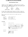
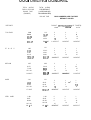
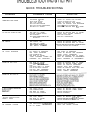
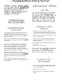
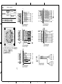
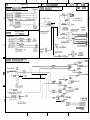
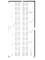
SMACK ‘N
ALIEN
OWNERS AND SERVICE MANUAL
INNOVATIVE CONCEPTS IN ENTERTAINMENT INC.
10123 MAIN ST.
CLARENCE, NEW YORK 14031
PHONE: (716) 759-0370
SERVICE PHONE: (716) 759- 0360 - %-ch
SERVICE FAX: (716) 759-0884
INTRODUCTION
l
l
ASSEMBLY
Game Features
Game Play
. Set-up
=-rI estmg
*
. Volume Control
CUSTOMIZING YOUR GAME
l
Programming Mode
MAINTENANCE
l
Cleaning & Lubrication
TROUBLESHOOTING & REPAIR
Quick Troubleshooting
. Operational Background
. Mechanical Repair
Electronic Repair
l
l
PARTS LISTINGS
Mechanical Parts
. Electronic Parts
Decals & Graphics
l
l
SCHEMATICS
WARRANTY INFORMATION
l
Schematics ”
Wiring diagrams
l
Basic Warranty
l
GAME FEATURES
We are proud to present The new Smack ‘N
AlienTM arcade game. We have succeeded
in taking an old arcade favorite and
changing it into a new and exciting game by
adding features not available in any of the
previous “Wacky” games.
The game is presented in a unique
multidimensional cabinet that includes a
beautifully sculpted astronaut figure,
colorful graphics, and truly funny alien
sound effects.
The astronaut body is made out of a high
impact fiberglass gel coat material with the
graphics clear coated into it.
Inside the astronauts “belly” are the aliens
that you must beat back into the astronaut
to win the game. The “aliens” are virtually
unbreakable injection molded plastic
assemblies that incorRorate multicolor
lighting. The lighting ‘consists of vibration
proof LED’s
The game electronics are designed from
reliable parts proven in years of service in
other games. We have purposely used
“low tech” components in an effort to make
this a more robust, cost effective design
that is also easy to service.
All of the cabinet decals are laminated with
a glossy high strength polyester overlay for
a rich glossy look and great scratch and
chemical resistance.
The Smack ‘N AlienTM game also includes
an adjustable Ticket Bonus for winning the
game. Of course, you have full control of all
game functions and ticket payout
percentaging with our extensive software
programming capabilities.
GAME PLAY
The game play is basically the same as
other “Wacky” games with one big
difference....” DON’T HIT RED ALIENS”.
In this game you can only hit the aliens
when they are GREEN in color. If you hit
the aliens when they are RED, the game
will temporarily stop to penalize you for your
error.
The game is broken up into three “Rounds”
and the game is over at the end of the third
round.
When the game is over your score is
displayed along with information on how
many tickets you have won. After this
display, the game will also give you the high
score of the day.
After a short period of time, the attract
mode will be displayed. This mode will
show the high score of the day, and will tell
the customer how many points they must
get to win the ticket bonus. The display will
also tell the customer how big the ticket
bonus is.
HS3tlVltSL Y
SET UP
BEFORE YOU BEGIN
WARNING: WHEN INSTALLINGTHIS GAME, ATHREE
PRONG GROUNDED A.C. RECEPTACLE MUST BE
USED. FAILURE TO DO THIS COULD RESULT IN
SERIOUS INJURY TO YOURSELF OR OTHERS.
FAILURETO USE A GROUNDED RECEPTACLE COULD
ALSO CAUSE IMPROPER GAME OPERATION, OR
DAMAGETHE ELECTRONICS.
DO NOT DEFEATTHE GROUND PRONG ON THE
POWER CORD FOR THE SAME REASONS AS GIVEN
ABOVE. USING AN IMPROPERLY GROUNDED
OUTLET COULD VOID YOUR WARRANN.
1. We will assume you have taken the box
off of the game skid to access this
manual.
2. Remove the game from the packing sk’d.
3. Find the permanent location for the game
and see that the game is level. This can
be done by the following:
l
l
Check to see if you can rock the
game. If you can, you need to use
the adjustable feet on the bottom
of the game.
Open the coin door. On the inside
left of the game are the latches
that open the top of the cabinet.
Open the latches. The top of the
game should open and close
smoothly. If it doesn’t, the game is
out of square. If the top of the
game binds on the back of the
cabinet, lower the front left leveler.
If the top of the game binds on the
front of the cabinet lower the rear
left leveler.
4. Plug the game into a good working A.C.
Receptacle.
NOTE: IT IS EXTREMELY IMPORTANT
THAT THE A.C. OUTLET USES THE
PROPER VOLTAGE TO ENSURE
PROPER FUNCTION OF THE ALIENS. DO
NOT USE AN EXTENSION CORD
UNLESS ABSOLUTELY NECESSARY. IF
YOU MUST USE AN EXTENSION CORD,
MAKE IT AS SHORT AS POSSIBLE, AND
MAKE SURE IT IS AT LEAST A 16 GA.
CORD THAT IS U.L /CSA OR CE
APPROVED.
IF YOUR VOLTAGE IS NOT WITHIN THE
NORMAL SPECIFICATIONS FOR THIS
GAMES RATING, PLEASE CONSULT
OUR SERVICE DEPARTMENT BEFORE
USING THIS PRODUCT. WE WILL
ADVISE YOU ON ADJUSTMENTS THAT
CAN BE MADE TO ASSURE SAFE AND
PROPER OPERATION OF THE GAME.
GAME TESTING
1. If your game uses tickets, it is important
to load tickets into the game at this time.
If your game is set to use tickets and they
are not in the game, you will get a CALL
ATTENDANT error.
2. Run coins through each coin slot at least
IO times to assure proper operation of the
micro switches.
3. When you power up the game look on
the upper right hand corner of the display
unit. If you see a single red dot in the
corner, you have a coil bed error that
needs to be repaired.
4. Check to see that the aliens seem to
move properly during the game.
5. Check to see that the ticket dispenser
works when the game is over.
GAME VOLUME
There are 2 volume control pots located on
the Main P.C. board. Adjust these to a
suitable volume level.
PLEASE ADJUST EACH POT THE SAME
AMOUNT TO RETAIN THE PROPER
SOUND BALANCE.
LUS I uIVIILII\Iu Y uun UnlVllZ
PROGRAMMING MODE
Programming of the Smack ‘N AlienTM game is accomplished through the 3 push buttons
located just inside the coin door. The left hand button is used to move back through the stated
options. The center button is used to select the available options, and the right hand button is
used to move forward through the stated options.
oBACK
S&CT
PRESS TO VIEW
PREVIOUS
SELECTION
FOR%ARD
PRESS TO
PRESS TO VIEW
SELECT
NEXT
SELECTION
The option menus are basically menus wirh sub-menus for each option. For example: You
start with the main menu. Using the forward or back button you will see sub menus such as
“tests”, “audits”, etc. When you reach a menu you want, you press the center button to select
it.
Below is a listing that shows the Main Menu with the sub-menus shown below it.
MAIN MENU
START GAME
“TESTS”
RETURNS TO NORMAL GAME PLAY
GOES TO TEST MENU
“ADJUSTMENTS”
“AUDITS” MENU
GOES TO ADJUSTMENTS
GOES TO AUDITS MENU
“SCORE STATS”
GOES TO SCORE STATISTICS MENU
MENU
TEST MENU
MAIN MENU
RETURNS TO MAIN MENU
ALIEN TEST
PRESS FORWARD TO SELECT COIL, PRESS PREVIOUS FOR UP
COIL BED’
CYCLES
l
THROUGH ALIENS AND WILL
REPORT ANY ERRORS
WILL DISPLAY “NO ERRORS” IF WORKING PROPERLY
IF
/ DOWN
<RESENT
’ WILL FLASH ALIEN IN ERROR RED + GREEN ALTERNATELY IF BAD
*WILL BYPASS BAD ALIEN DURING NORMAL GAME PLAY IF POSSIBLE
*WILL DISPLAY A RED PIXEL IN UPPER RIGHT CORNER OF GAME
DURING NORMAL GAM PLAY
SWITCH TEST
FLASH TEST
ALIEN COLOR IS RED IF DOWN, GREEN IF UP
I=
1sTSET OF FLASHERS
2= 2ND SET OF FLASHERS
3= 3RD SET OF FLASHERS
4= 4TH SET OF FLASHERS
LlJ> I
uIVIILII\Iu
SOUND TEST
FORWARD
SELECTS
“NNN” CREDITS
SHOWS
OF
TICKET TEST
SHOWS
#
RESTART
CREDITS
TICKETS
Y
LE FT
RESET
uul-i ednlvlt
SOUND
INCREMENT
TO PAY
TICKETS
PREVIOUS
USING
SELECTS
PREVIOUS
FORWARD
WILL ADD 2
IF NECESSARY
DEC
NEXT
USING
TICKETS . P R EVIOUS
ADJUSTMENTS MENU
MAIN MENU
RETURNS
FACTORY
LOADS
SET
DIFFICULTY
TO
MAIN
FACTORY
MENU
DEFAULT
JACKPOT I SCORE
“TOO EASY”
PLATEAU
VALUES,
PROMPTS
FOR
VERIFICATION
DIFFICULTY
“EASY”
“MEDIUM”
“HARD”
“VERY HARD”
PAYOUT
SET
DEFAULT)
(FACTORY
DEFAULT)
(FACTORY
DEFAULT)
(FACTORY
DEFAULT)
“LOW”
“MEDIUM”
“HIGH”
TICKET SCALER
(FACTORY
TICKET
SCHEDULE
MULTIPLIER
Xl
x2
x3
x4
JACKPOT SET
JACKPOT
AMOUNT
25
50
75
100
<’
1.50
200
250
500
CREDIT SET
NUMBER OF COINS PER CREDIT
FREE
PLAY
1 COIN
(FACTORY
2COlNS
3COlNS
4 COINS
CONTINUOUS
ATTRACT SET
ATTRACT TIME
DISABLED
MODE FOR TESTING GAME
DEFAULT)
FORWARD
WILL
c;ua 1 WlViILll’lti YUUK ~NIVlt
ATTRACT SET
ATTRACT TIME
DISABLED
1 MINUTE
(FACTORY
DEFAULT)
1 POINT PER TICKET
2 POINTS PER TICKET
(FACTORY
DEFAULT)
ROUND TIME
2 TO 40 SECONDS
(DEFAULT
COIL ARMING
AUTO BYPASS OF BAD ALIENS AT POWER UP
2
3
MINUTES
MINUTES
4 MINUTES
5 MINUTES
1 0 MINUTES
2 0 MINUTES
TICKET SIZE
POINTS PER TICKET
14
SECS.)
DISABLE= AUTO BYPASS OFF
ENABLE=
TICKET MECH
AUTO
BYPASS
ON
(FACTORY
TICKET MECH ON /OFF
DEFAULT)
(DEFAULT = ON)
AUDIT MENU
MAIN MENU
RETURN TO MAIN MENU
CLR AUDITS
CLEARS
COINS
SHOWS TOTAL COINS TAKEN
PAYOUT
SHOWS TOTAL TICKET PAYOUT
JKPOTS
SHOWS
AUDITS
TOTAL
PROMPTS
JACKPOTS
FOR
WON
VERIFICATION
bU3
I
UlVllLllYU
1 UUI
I
UAIVIL
SCORE STATS
MAIN MENU
RETURN TO MAIN MENU
CLR STATS
CLEARS
STATISTICS,
PROMPTS
FOR
VERIFICATION
0 = NUMBER OF GAMES THAT SCORED BETWEEN O-9
10 = NUMBER OF GAMES THAT SCORED BETWEEN lo-19
20 = NUMBER OF GAMES THAT SCORED BETWEEN 20-29
30 = NUMBER OF GAMES THAT SCORED BETWEEN 30-39
40 = NUMBER OF GAMES THAT SCORED BETWEEN 40-49
50 = NUMBER OF GAMES THAT SCORED BETWEEN 50-59
60 = NUMBER OF GAMES THAT SCORED BETWEEN 60-69
70 = NUMBER OF GAMES THAT SCORED BETWEEN 70-79
80 = NUMBER OF GAMES THAT SCORED BETWEEN 80-89
90 = NUMBER OF GAMES THAT SCORED BETWEEN 90-99
lOO= NUMBER OF GAMES THAT SCORED BETWEEN 100.109
110=
NUMBEROFGAMESTHATSCORED BETWEEN 110-119
120=
130=
NUMBER OF GAMES THAT SCORED BETWEEN 120-129
NUMBER OF GAMES THAT SCORED BETWEEN 130-139
140=
150=
NUMBER OF GAMES THAT SCORED BETWEEN 140-149
NUMBER OF GAMES THAT SCORED BETWEEN 150-159
160= NUMBER OF GAMES THAT SCORED BETWEEN 160 AND UP
MAX= MAXIMUM SCORE
TICKET
SCHEDULE
THIS TICKET SCHEDULE REFLECTS THE TOTAL
ALIENCOUNT
NORMALIZED (SCALED) TO 14 SECOND
DEFAULT ROUNDS. THIS MEANS IF FOR EXAMPLE THE ROUND TIME IS SET TO :
14 SECONDS (DEFAULT)
ALIEN COUNT FOR GIVEN PAYOUT LINE ARE 100% (14114) OF SHOWN
(NORMALIZED) VALUES IN TABLE
10 SECONDS
ALIEN COUNT FOR GIVEN PAYOUT LINE ARE 71.4% (10114) OF SHOWN
(NORMALIZED) VALUES IN TABLE
20 SECONDS
ALIEN COUNT FOR GIVEN PAYOUT LINE ARE 143% (20114) OF SHOWN
(NORMALIZED) VALUES IN TABLE
NOTE: THIS KEEPS TICKETS SCHEDULE RELATIVE (SCALED) TO A FIXED REFERENCE POINT.
bU3
I uIVIILIIVU
TOTAL ALIENS
FOR 20 SECOND
ROUND TIME
(EXAMPLE)
1 WUI
TOTAL ALIENS
FOR DEFAULT
(14 SECOND OR
OR NORMALIZED)
ROUND TIME
TOO EASY
A
S
Y
MEDIUM
HARD
l-19
20-39
40-59
60-79
8O&UP
1-13
14-27
28-41
42-56
56 & UP
2
4
6
IO
J ACKPOT
4
6
8
14
JACKPOT
l-30
31-60
61-90
91-111
12O&UP
l-21
22-42
2
4
6
10
JACKPOT
4
6
8
14
JACKPOT
l-35
36-70
71-106
l-28
26-49
50-74
107-l 39
140 &UP
75-97
98&UP
1-44
45-90
91-134
135-l 59
171 &UP
VERY
BOLD NUMBERS ARE FACTORY
DEFAULT VALUES
PAYOUT SETTING(NUMBER
OF TICKETS)
LOW
‘MEDIUM
HIGH
DIFFICULTY
E
1 UfTIVIL
HARD
l-49
50-97
98-144
145-l 93
192 & UP
43-63
64-83
84&UP
1-31
32-63
64-94
95-119
12O&UP
l-34
35-68
69-101
102-134
135 & UP
2
4
6
10
JACKPOT
2
4
6
10
JACKPOT
2
4
6
10
JACKPOT
4
6
8
14
JACKPOT
4
6
8
14
_’
6
a
10
16
JACKPOT
6
8
10
16
JACKPOT
6
a
10
16
JACKPOT
6
8
10
16
JACKPOT
JACKPOT
4
6
8
14
6
8
10
16
JACKPOT
JACKPOT
MAIN I tNANGt
CLEANING
Cleaning is easily accomplished by using
any mild glass cleaner or mild soapy
solution to remove dirt and grease. To keep
the game looking it’s best however, it would
be a good idea to periodically finish
cleaning the game with the following
materials:
l
Automotive paste wax - This
should be used on all of the
Astronaut body surfaces to help
seal and preserve the painted
finish.
LUBRICATION
We DO NOT recommend the use of any
lubricants anywhere on the game.
The only moving parts on the game are the
Alien Head assemblies. If you notice any
sticking or binding of the Alien Heads check
the following:
l
l
. Spray furniture polish - this should
be used to clean and protect all of
the other exterior game surfaces.
We recommend the use of
PledgeTM
furniture polish.
Dirt on the solenoid shafts - Remove the
solenoid shafts and clean with isopropyl
alcohol. Finish wiping clean with a good
grade of spray furniture polish only.
Check that the micro switch actuators are
not too tight. If the switch actuators are
too tight, bend by hand so that they do
not impede the up or down movement of
the Alien Head.
9 Wear - If excessive solenoid body wear is
noted, replace the solenoid coil.
. Upholstery cleaner -this can be
sprayed onto the cloth surface of
the mallet. and vacuumed off when
dry.
QUICK TROUBLESHOOTING
PROBABLE CAUSE
PROBLEM
SOLUTION
GAME WILL NOT START
N O P O W E R T3 G A M E
MAIN FUSE B-OWN
BAD COIN SWITCH
BAD COIN MECHANISM
BAD COIN DCOR HARNESSING
BAD MAIN P.C.BOARD
CHECK
CHECK
CHECK
ADJUST
CHECK
REPAIR
NO OR LOW GAME VOLUME
BAD MAIN P.C. BOARD
VOLUME TURNED DOWN
BAD SPEAKER
B A D SPEAKE? H A R N E S S I N G
REPAIR OR REPLACE MAIN P.C. BOARD
ADJUST BOTH VOLUME CONTROLS
REPLACE SPEAKER
REPLACE HARNESSING
NO
DISPLAY
BAD
BAD
BAD
BAD
NO
TICKET
DISPLAY UNIT
MAIN P.C. BOARD
COMBO 30ARD (110)
DISPLAY HARNESS
A.C. OUTLET FOR VOLTAGE
OR REPLACE FUSE
OR REPLACE COIN SWITCH
OR REPLACE COIN MECHANISM
& REPAIR HARNESSING
OR REPLACE MAIN PC. BOARD
REPAIR OR REPLACE DISPLAY UNIT
REPAIR OR REPLACE MAIN P.C. BOARD
REPAIR OR REPLACE BAD COMBO BOARD
REPAIR OR REPLACE HARNESS
NO TICKETS IN DISPENSER
BAD TICKET DISPENSER
BAD HARNESSING
BAD MAIN P.C. BOARD
TICKET DISPENSER TURNED OFF
DISPENSER
SET
IMPROPERLY
ADD TICKET TO DISPENSER
REPAIR OR REPLACE BAD DISPENSER
REPAIR TICKET HARNESSING
REPAIR OR REPLACE MAIN P.C. BOARD
TURN ON DISPENSER IN PROGRAMMING
ADJUST DISPENSER IN PROGRAMMING
BAD
BAD
BAD
BAD
BAD
BAD
BAD
MAIN P.C. BOARD
COMBO 3OARD
COIL BED HARNESSING
ALIEN HEAD P.C. BOARD
ALIEN HEAD HARNESS
COIL BED HARNESSING
CABINET HARNESSING
REPAIR OR REPLACE MAIN P.C. BOARD
REPAIR OR REPLACE COMBO BOARD
REPAIR OR REPLACE HARNESSING
REPLACE ALIEN HEAD ASSEMBLY
REPAIR OR REPLACE ALIEN HEAD ASSY
REPAIR COIL BED HARNESSING
REPAIR CABINET HARNESSING
&Ef;f~TEEs NOT RESPOND
BAD
BAD
BAD
BAD
MICRO SWITCH
COMBO BOARD
MAIN P.C. BOARD
COIL BE3 HARNESS
ADJUST
REPAIR
REPAIR
REPAIR
“SECRET” BONUS ROUND
DOESN’T WORK
BAD SLAM SWITCH
BAD MAIN P.C. BOARD
BAD HARNESSING
ADJUST OR REPLACE SLAM SWITCH
REPAIR OR REPLACE MA1N.P.C. BOARD
REPAIR HARNESSING
NO
BAD BRIGHTSTICK FLORESCENl
NO A.C. POWER
REPLACE BULB ASSEMBLY
CHECK FOR PROPER VOLTAGE
DISPENSING
ALIENS DO NOT LIGHT
ALIENS DO NOT POP UP
MARQUEE
LIGHTING
OR REPLACE MICRO SWITCH
OR REPLACE COMBO BOARD
OR REPLACE
HARNESS
WARNING: ALWAYS REMOVE POWER
TO THE GAME BEFORE A-lTEMPTING
ANY SERVICE, UNLESS NEEDED FOR
SPECIFIC TESTING. FAILURE TO
OBSERVE THIS PRECAUTION COULD
RESULT IN SERIOUS INJURY TO
YOURSELF OR OTHERS.
OPERATIONAL
BACKGROUND
TROUBLESHOOTING
PHILOSOPHY
To find problems with the game, always first check
what should be obvious. See that the game is
plugged in, and that all of the fuses on the game are
good. This includes the fuse that is located INSIDE
the power module.
Next, check to see that all of the connectors are
firmly seated, and that none of the wires have pu:led
out of them.
When trying to find out if specific components are
bad or not, try swapping them with components
from another player station to see if the problem
moves with the component, or stays where it was.
This will help you to know if you have a problem
with a specific component, or maybe a problem with
either the wiring or the Main P.C. Board.
Use extreme caution when using probes or volt
meters if the game is powered up. If doing continuiv
checks, it is important to disconnect the harnessing at
both ends, as attached they may yield erroneous
results.
If P.C. Boards are suspected as causing problems,
check to see that all of the I.C. chips are firmly seated
on the boards.
MECHANICAL REPAIR
COIL BED
The coil bed houses all of the moving
parts in the Smack ‘N AlienTM game.
The Solenoid Coils and Alien Heads can
be serviced while the coil bed is still
installed in the game. The astronaut
body must be removed to service the
Alien Heads. The entire coil bed may
also be removed if desired for service.
ASTRONAUT BODY
REMOVAL
1. Open the coin door. There are 2 latches on the
upper left hand side of the game that lock the top
of the game to the cabinet. Unlock the 2 latches.
2. Lift the top of the game open by lifting up on the
knees of the astronaut.
3. There are 4 bolts and washers that secure the
astronaut to the top of the cabinet. Remove the 4
bolts and washers.
4. Carefully lift the astronaut body straight off of the
Alien heads.
5. Replace in the reverse order.
NOTE: BE SURE WHEN TIGHTENING THE BOLTS ON
THE ASTRONAUT BODY THATTHE ALIEN HEADS ARE
CENTERED IN THE HOLES IN THE ASTRONAUTS
CHEST. FAILURE TO DO SO COULD CAUSE THE
ALIENS TO BIND ON THE SIDES OF THE HOLES.
SOLENOID COIL
REPLACEMENT
1. Turn off all A.C. power and unplug game. Open
the coin door and unhook the latches that secure
the top of the cabinet.
2. Open the top of the cabinet.
3. Determine which coil is defective and remove as
follows:
I KUUtsLt3HUU
A) Remove the plastic switch actuator at the
bottom of the Alien Head Shaft by
removing the Allen Head Screw and
washer. Pull the actuator off the shaft.
B) Remove the rubber bumper and plastic
washer from the Alien Head Shaft.
C) Remove the anti-rotation pin from the
micro switch / solenoid mounting flange
by twisting it from the flange.
D) Remove the 2 Nylock Nuts and washers
that secure the solenoid into the coil bed
assembly.
I Il’Jti & KtrAlK
3. Remove the rubber bumper and plastic washer
from the Alien Head Shaft.
4. Remove the anti-rotation pin from the micro switch
/ solenoid mounting flange by twisting it from the
flange.
5. Disconnect the 3 pin connector from the Alien
Head assembly at the top of the coil bed assembly.
6. Lift the Alien Head assembly from the coil bed
assembly.
7. Reassemble in reverse order.
E) Remove the mounting flange and carefully
lower the solenoid coil from the coil bed
assembly.
F) Disconnect the 2 fast-on tabs the connect
the Solenoid coil to the coil bed
harnessing. Slide the coil off of the Alien
Head shaft.
C) Connect the 2 fast-ons from the Solenoid
coil to the coil bed harnessing. BE SURE
TO CONNECTTHE ORANCETOTHE
ORANGE WIRE, AND THE BLACKTOTHE
BLACK WIRE.
H) Slide the solenoid onto the Alien Head
Shaft and up into the coil bed assembly.
NOTE: IT IS IMPERATIVETHATTHE
SOLENOID COIL WIRES ARE KEPT OUT
FROM UNDERTHE SOLENOID COIL
WHEN INSTALLING IT INTO THE COIL
BED. FAILURE TO KEEP THE WIRES OUT
OFTHE WAY CAN RESULT IN THE
SOLENOID COIL NOT FULLY SEATING
INTO THE COIL BED ASSEMBLY AND
CAUSING WIRE PINCHING OR DAMACE
TO THESOLENOID COIL ITSELF.
ELECTRONIC REPAI R
ELECTRONIC AND
ELECTRICAL REPAIR
The following section will describe repair procedures
and trouble shooting hints for the game electronics.
Please read the section “Operational Background” in
the beginning of Maintenance and Trouble Shooting
to get a good understanding of the game’s basic
operating parameters.
I) Slide the Solenoid mounting flange up ‘nto
position and secure with the nylock nuts
and washers.
J) Finish assembly of the unit observing how
the other assemblies are constructed.
ALIEN HEAD ASSEMBLY
REPLACEMENT
1. Open the game and remove the Astronaut body as
described above.
2. Remove the plastic switch actuator at the bottom
of the Alien Head Shaft by removing the Allen
Head Screw and washer. Pull the actuator off the
shaft.
USE EXTREME CAUTION WHEN USING VOLT
METERS TO DO CIRCUIT CHECKS IF THE GAME
POWER HAS BEEN LEFT ON.
ALWAYS REMOVE ANY BATTERY BACK-UP
POWER WHEN WORKING ON THE GAME. THIS
IS NECESSARY, AS SOME CIRCUITS ARE
CONSTANTLY UNDER POWER FROM THE
BATTERY.
WHEN USING A VOLT METER, BE SURE IT IS
SET TO THE CORRECT VOLTAGE OR
RESISTANCE RANGE ,BEFORE USING. THIS CAN
PREVENT POSSIBLE DAMAGE TO THE P.C.
BOARD OR MISDIAGNOSIS.
ALWAYS REMOVE POWER TO THE GAME
W’$E~D~~UCCING
OR UNPLUGGING P.C.
IT IS NECESSARY TO USE I.C.E. REPLACEMENT
PAnTq ,Tn CDNT!.NUE WARRANTY COVERAGE.
111,111
USE OF NON-I.C.E. APPROVED PARTS WILL
NOT ONLY VOID YOUR WARRANTY, BUT
C OULD CAUSE SERIOUS HARM TO THE GAME,
OR CAUSE SERIOUS BODILY INJURY.
IF YOU HAVE
REPAIR AFTER
OUR SERVICE
l-800-342-3433
ANY QUESTIONS REGARDING
READING THIS SECTION, CALL
DEPARTMENT AT
BEFORE
PROCEEDING.
MAIN & COMBO
P.C. BOARD
The Main & Combo (input / output) P.C. boards are
assessable through the top of the game. Remove all
power before servicing these P.C. boards. When reinstalling these boards, use the original mounting
holes in the cabinet whenever possible.
DISPLAY P.C. BOARD
Remove the display board from the game as follows:
1. Open the lock at the top of the control panel.
2. Lift up on the lock to lift the display graphics
panel. Pull out on the lock to pull out the bottom
of the display.
3. Remove the display from the game.
4. Remove the fasteners that hold the display panel
to the game.
5. Remove the harness connectors from the displa:i
board.
6. Assemble in the reverse order
CHANGING VOLTAGES
The Smack ‘N AlienTM arcade game is built for
110-120 VAC input voltage. If you need your game
to operate on a different voltage, the following must
be changed:
FOR 90-l 00 VAC OPERATION
. STEP UP THE FLORESCENT LIGHTING
. RE-STRAP MAIN POWER TRANSFORMER
FOR 220-240 VAC OPERATION
* STEP DOWN FLORESCENT LIGHTING
. RE-STRAP MAIN POWER TRANSFORMER
* CHANGE VOLTAGE SELECT ON
SWITCHING POWER SUPPLY
FOR EITHER OF THESE CHANGES,
CONTACT OUR SERVICE DEPARTMENT.
WE WILL SUPPLY YOU WITH THE
PROPER TRANSFORMER FOR THE
FLORESCENT LIGHTING, A
TRANSFORMER INTERFACE ADAPTER
CABLE, AND DIRECTIONS ON HOW TO
ADAPT YOUR GAME.
FUSE VALUES AND
LOCATIONS
3 I N 1 (COMBO) P.C. BOARD
Fl - 15 AMP, 32
F2 - 4 AMP, 250
F3 - 4 AMP, 250
F4 - 4 AMP, 250
F5 - 4 AMP, 250
F6 - 4 AMP, 250
F7 - 4 AMP, 250
F8 - 4 AMP, 250
F9 - 4 AMP, 250
FlO - 7 AMP, 250
Fl 1 - 5 AMP, 250
VOLT
VOLT
VOLT
VOLT
VOLT
VOLT
VOLT
VOLT MDQ (SLOW B L O W )
VOLT
VOLT ,‘
VOLT
ON CABINET FLOOR FUSE BLOCK
3 AMP, 250 VOLT MDQ (SLOW BLOW) X 2
8106
FP2007
HH5005
HD20224X
MECHANICAL PARTS
MICRO SWITCH, CUSTOM LEVER
SPEAKER, 4” ROUND
TICKET DISPENSER, ENTROPY
5 VOLT COUNTER ASSEMBLY
HARNESS, ALIEN COIL BED
SOLENOID COIL
TRANSFORMER
HARNESS, EARTH GROUND
201
CHROME T MOLDING
213
WA1003
BLACK T MOLDING
WA1 004
WA1005
UPPER
LOWER
WA1010
WA1 050
HOSE MOUNTING PLATE
WA1051
WA1053
LATCH
PLUNGER
WA1054
WA201 1
LIMITING PIN
ALIEN HEAD ASSEMBLY
WA3002
WA3003
SPRING CAP
COIL CAP
WA3004
WA3006
BUSHING, MALLET
ALIEN SHAFT CAP
WA3007
WA3008
GRILLE, 16” X 5”
GRILLE, 5” X 5”
WA3020
WA3021
ASTRONAUT BODY
ASTRONAUT ARM
WA3022
WA4001
ASTRONAUT LEG
WA4002
WA4010
HOSE, RED
WA401 1
WA4012
GROMMET, COIL BED
BUMPER, ALIEN SHAFT
4004
5014
COLLAR RUBBER (LARGE BUMPER)
CAM LOCK
6250
6’251
8 - 3 2 X 314 A L L E N H E A D C A P S C R E W
NYLON WASHER ,905 OD X ,510 ID
WA7001
WA7002
DECAL,
DECAL,
6252
6253
NYLON WASHER 1.375 OD X 525 I D
ROLL PIN 118” X l/16”
WA7003
WA7004
DECAL, WHEEL
DECAL, ALIEN N
PC60631
UC1 0 0 2
i/4 - 20 CABINET INSERT
PODIUM LATCH BRACKET
WA7005
WA7006
DISPLAY PANEL
DECAL, REAR PANEL
WA7007
WA7008
DECAL, ICE
DECAL, ALIENS ,‘
WA7027
MARQUEE
SERVICE MANUAL
SPACER
GAS
GAS
SHOCK
SHOCK
MOUNTING
MOUNTING
PLATE
PLATE
GAS SHOCK
HOSE, BLUE
1008
1017
2005
2132
2289
WA2012
WA2031 X
WA2032X
WA2034X
WA205 1 X
WA2053X
WA2056X
WA2057X
WA2058X
WA2059X
WA2061X
WA2062X
WA5001
POWER SUPPLY, SWITCHING
SWITCH, SLAM
DISPLAY PC BOARD, TRI COLOR
3 IN 1 (COMBO) P.C. BOARD
MAIN P.C. BOARD
HARNESS,
DISPLAY
HARNESS,
SPEAKER
HARNESS,
HARNESS,
HARNESS,
HARNESS,
HARNESS,
HARNESS,
MARQUEE
DOOR
POWER
ALIEN BED INTERFACE
TRANSFORMER
WEDGE SOCKET
COIN DOOR
MALLET
ELECTRONIC / ELECTRICAL
PARTS
211
WA2060X
WA3001 X
WA2002X
WA2004X
WA201 0
SWITCH, LOW
BULB, #555
TICKET
LED HOLDER
BULB, #906
BULB, GE BRIGHT STICK
RESET - PROGRAMMING BUTT’ON
GRAPHICS & DECALS
WA9001
REAR UPPER PANEL
ASTRONAUT BED
COUNTER
LOWER
SET
4
TLE
3
WIRING DIAGRAM
iSCR,PT,ON HWAZ060X-ALIEN
HARNESS
iTTE
11/19/90
RLYISED
D
,x54 m
I
ALltNM??
SD
BEI) F’LENhME
UFuviNBY
I
2/2$/99
PAGE
ALIEN CiOIL
8 PER GAME
WHITE
-
1
2
RMO
22
5
6
1 OF 6
20
29
J
140022AWG
T”RN.s
SPN
a51
60
61
30
53
-
(
WllOW
t
violet/red
q while/red
/
YdlOW
12
13
C
#236412 VOLT DC FAN
1
;
0
rl
B ALIEN LED
F ALIEN LED
39
45
46
-
63 PIN CIR.RECEP.PNL.
MALE PIN #8114
B
62
63
41
56
-
MT. #8113
20
21
d
violellqreen
whiteiween
:
3
35
36
33
34
A ALIEN SW
58
59
57
B ALIEN SW
10
11
24
9
51
52
P
50
C ALIEN SW
43
44
42
25
0 E ALIEN LED
t-l ALIEN SW
WIRING DIAGRAM
ILE
I
:SCRIPTION
D
llWA2059X
ALIEN
INTERFACE
HARNESS
DRAWNBY RMO
t T E 11/19/98 REVISED Zf’ZX9 PAGE 2
I
O F
G
I
-
J3
COIL SWT #6
COIL swr #7
COIL SWT #6
COIL swr #5
COIL SWT &I
COIL SWT #3
COIL SWT #2
COIL SW? #I
JO
1
2
3
4
5
6
7
a
9
10
COIL GND #2
COIL GND #I
COIL GND iM
COIL GND #3
COIL GND #5
COIL GND #6
COIL GND #7
KEY
COIL GND !fB
25
42
50
57
56
la
10
35.
JlO
LED 111 RED
LED #6 GRN
LED #7 GRN
LED #6 GRN
LED #5 GRN
LED #4 GRN
LED #3 GRN
LED #2 GRN
KEY
LED #1 GRN
C
-
E
63 PIN CIRCULAR PLUG #8111
FEMALE PIN #8112
CLAMP#8110
violeUbrown
whltelgray
whlteiwolet
whltelblue
whlteigreen
wh~telyeltaw
whltelarange
white/red
g-%-
KEY
+
b
+
b
+
w
b
F
60
29
6
13
21
36
46
54
ä
6,
COtL PWR 111
KEY
COIL PWR #2
COIL PWR #3
COIL PWR #4
COIL PWR #5
COIL PWR #6
COIL PWR #7
COIL PWR 118
63
59
52
44
27
19
11
36
J6
LED
LED
LED
LED
LED
-
1
2
3
4
5
6
7
a
#O
#7
#6
#5
#4
LED #3
LED #2
N/C
N/C
RED
RED
RED
RED
RED
KEY
RED
RED
2
3
4
5
6
7
a
9
IO 1
.,
KEY
b12V
GND
GNO
t5v
3
24
33
41
/
4
3
2
1
RED
BLACK
0,
TO 3 IN 1 BOARD
Jll
+5” DC SWITCHER
+12V
+I?/
+I&!
+,6V
TO
T I ?ANSFORMER
AC
AC
AC
AC
TO MAIN DOARD
llHD20224X-COUNTER
LABEL ‘C’
LABEL “T
TRANSFORMER
TRANSFORMER
TRANSFORMER
TRANSFORMER
4 PIN CAP #2150
FEMALE PIN #2176 I
-
“650
d-550
#rm
“650
TO
S WITCHING
SUPPLY
TO COIN DOOR LAMPS
fm5
C,
-
TO MAIN BOARD
53
TICKET
ENARI F
II
KEY
#2239
E3
d651 q
10 PIN HOUSING 1(2291
WNTIACT PIN #2Ml
-
I4
TO MAIN
BOARD
RESET
AUDIT #2
AUDIT 111
LIFE SWITCH
TICKET NOTCH
GROUND
COIN2
COIN1
KEY #2239
J1
,.
blacklblue
9
Qray
while/gray
a
7
blue
6
5 blacklred
4
blacklbrawn
3
2 eK E Y
1
D------
TO LOW TICKET
SWITCH
J- t
“ldb” i
black/red
black/t )IowI
I
HARNESS
I
DF.4WNBY
5v
4
3
LE
2
FILENAME
WACK AN ALIEN
SCRlPTlON
#WAZO51X-DISPLAY HARNESS
iSC”lPTlON
ALIENM.VSD
llWA2055X.AC
DRAWN
1
PAGE
BY
4OF6
DATE
REVISEO
POWER HARNESS
1 l/19/98
2/25!99
3 3 I N 1 BOARD J13
2011 PIN
D
TO
SWITCHING
SUPPLY
TO TRANSFORMER OR
ADAPTERHARNESSES
TO BRIGHT
SPEAKER HARNESS
PART OF WA2057X
SCRlPTlON
C
TRANSFORMER
iSCRlPTlON
#WA2056X-MARQUEE HARNESS
MARQUEE
TO 3 IN 1 BOARD
B
J12
1GV FLASHER PWR
KEY #2239
I
ItiER M A R Q U E E
LAMPS
TO 3 IN 1 “OAR0
FLASH UP MARQUEE
FLASH LOW BOX
f
FLASH LOW MARQUEE
FLASH UP BOX
TO U P P E R B O XX
12 CM906 BULBS
2 CM555 BULBS
E:: /jZEII=n a
BWAmU(-WEDGE SOCKET
14 PER G*ME
1
I”
~n~x,rrnm.,co
) AC POWER
..^.._^I
fiWA6006X-STEP DOWN 220 VOLl ; OPTION
W6006-TRANSFORMER
MCI i&49-5120
PRIMARY
T O AC POWER
HARNESS
SECONDARY
TOBRIGHT
STICKS
(
I
C
TO 3 IN 1 BOARD
FEMALE PIN #2102
-
J7
WHITE/VIOLET
TO
TRANSFORMER
I
2-51-9902
TO 3 IN 1 BOARD
3 AC POWER HARNESS
.ACADAPTERHARNESS
C
ov
-
12ov
1 oov
ov
u
3
4
5
6
6 PIN PLC
SOLID PII
r
WHliELUE
(
)
>
t
GRAYiWHlTE
I
)
PRIMARY
thWA6006JX-STEP UP 90 VOLT OPTION
#PC20428TRANSFORMER
MCI #4-06-6416
SECONDARY
TO BRIGHT
STICKS
TITLE
WIRING DIAGRAM
c
L
P
--I
It
-
" -L-..-----
c "
A
-
"
-
v
-
-
t
I
i
I
u
/
-
I
-
1
34
J
w-7