1
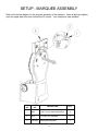
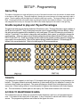
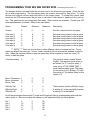
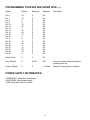
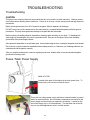
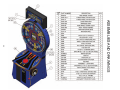
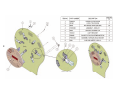
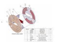
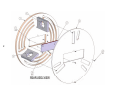
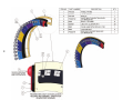
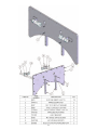
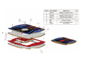
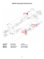
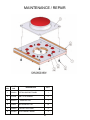
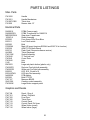
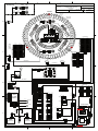
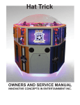
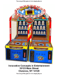
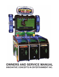
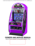
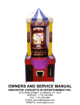
1
WEBSITE: www.icegame.com
TABLE OF CONTENTS
Safety
3
Setup and marquee assembly
4
Game Play - Credits and Payout percentages - Tickets
5
Pie values examples
6-7
Programming
8-9
Power supply Information
9-10
Assemblies
11-19
Pull arm assembly and diagram
20-21
Large Button assembly
22
Parts number listing
23
IREVISION D
10-31-08
2
SAFETY AND WARNINGS
BEFORE YOU BEGIN
WARNING: WHEN INSTALLING THIS GAME, A GROUNDED A.C. RECEPTACLE MUST BE USED. FAILURE
TO DO SO COULD RESULT IN INJURY TO YOURSELF OR OTHERS. FAILURE TO USE A GROUNDED RECEPTACLE COULD ALSO CAUSE IMPROPER GAME OPERATION, OR DAMAGE TO THE ELECTRONICS.
DO NOT DEFEAT OR REMOVE THE GROUNDING PRONG ON THE POWER CORD FOR THE SAME
REASON AS GIVEN ABOVE. USING AN IMPROPERLY GROUNDED GAME COULD VOID YOUR WARRANTY.
HAVE A QUALIFIED ELECTRICIAN CHECK YOUR A.C. RECEPTACLE TO BE SURE THE GROUND IS
FUNCTIONING PROPERLY.
INSTALLATION
The game comes ready to play with just a few simple things to keep in mind.
1. Plug the game into the A.C. outlet and turn on power to the game. The switch for the game is located on a
power module on the outside rear of the game.
THIS GAME IS DESIGNED TO DISSIPATE STATIC ELECTRICITY THROUGH THE GROUNDING PLANE OF THE
GAME. IF THE A.C. GROUND DOES NOT WORK, THE GAME COULD DISCHARGE STATIC ELECTRICITY
THROUGH THE GAME CIRCUITRY, WHICH COULD CAUSE DAMAGE.
2. Make sure the game is level after installation. It is necessary to make sure the game is level for safety
concerns.
3. Check that the A.C. voltage rating on the back of the game matches the A.C. voltage of your location.
4. Power cord replacement must be supplied by a trained technician.
THE POWER SUPPLY IS NOT VOLTAGE ADJUSTABLE. TO OPERATE THE GAME AT VOLTAGES OTHER THAN
THOSE IT WAS DESIGNED FOR. PLEASE CONTACT OUR SERVICE DEPARTMENT FOR VOLTAGE CONVERSION
INFORMATION.
WARNING
DO NOT remove any of the components on the main board (e.g. compact flash and eproms) while
the game is powered on. This may cause permanent damage to the parts and the main board. Removing any main board component part while powered on will void the warranty.
NOTE: THIS GAME IS INTENDED FOR INDOOR USE ONLY.
ON THE BACK PANEL OF THE GAME: WARNING: SHOCK HAZARD - DO NOT OPEN. REFER
SERVICING TO SERVICE PERSONNEL. THE GAME MUST NOT BE CLEANED WITH A WATER
JET.
3
SETUP - MARQUEE ASSEMBLY
Refer to the below diagram for the physical assembly of the marquee. Once all bolts are tighten,
open the upper back door and connect the AC power. Your marquee is now installed.
ITEM
NO.
PART
NO.
DESCRIPTION
QTY.
1
6082
1/4-20 x 2 Hex Head Machine Bolt
4
2
6075
1/4 x 3/4 FLAT WASHER
4
3
PW3132X MARQUEE ASSEMBLY
4
1
SETUP - Programming
Game Play
The object of the game is to stop the light ring on any of the three bonuses to win the amount of tickets shown
in the center of the light ring. The player begins by inserting the correct amount of coinage required to start a
game. Then the player pulls the large level to begin the light ring’s motion. The large red button will begin to
flash. Pressing this button will stop the light ring giving the value of the tickets for that pie. If the light ring
was stopped at the bonus pie, the player wins the bonus tickets displayed in the center of the light ring.
Credits required to play and Payout Percentages
The game has ticket payouts that are divided into 24 sections or pies. There are three bonus pies in addition to
the 24 pies for a total of 27. Each of the three bonus pies can be configured different for their difficulty. When
the game arrives the graphics will be installed for a two credit game (.50 cents US) assuming your location is
using a .01 cent ticket. If you desire to change the credit required to start a game, you will have to change the
payout graphics. When your game arrived a decal package should have been included (ICE part numbers
PW7115 and PW7116). These two packages should contain all the possible numbers required to change the
payout pies to the required setup. Remove the graphics already installed and discard. Peel and apply the
stickers to the recommended pie. Refer to the next page for ICE recommendations:
TICKETS
Your game has the capacity to hold up to 16 thousand tickets giving you plenty of play between collections. This game features automatic detection of tickets and will pay out whatever is owed to the
customer when tickets are replaced. The game will dispense tickets from both dispensers at the
same time. When loading tickets it is recommended to balance them between both ticket dispensers. The total number of tickets paid out are kept by the Ticket meter located in the coin door.
ACCESS TO MAINTENANCE AREA
The maintenance area is where you access the ticket dispenser, cash box, and programming buttons. It is located in the lower front of the game. A key is required to unlock each section to gain
access. The programming buttons are located in the upper coin door.
5
6
7
PROGRAMMING YOUR BIG WIN SUPER SPIN - Software game version 1.0
The program button is located inside the coin door next to the ticket and coin meters. Press this button to enter programming. The top display shows the current value held for that option. To cycle
through your options use the large red button on the control panel. To accept the current value
shown on the LED screen press the pull arm on the side of the cabinet to advance to the next option. This game has its coin wiring cash flow ready. Other options are available. Contact your ICE
sales representative for details. Refer to the chart below.
Option
Default
Minimum
Maximum
Description
Volume
5
0
8
Sets the volume level for the game.
Coin Input 1
Coin Input 2
Coin Input 3
Coin Input 4
Coin Input 5
Coin Input 6
2
0
0
0
0
0
0
0
0
0
0
0
9
9
9
9
9
9
Sets how many pulses to start a game.
Sets how many pulses to start a game.
Sets how many pulses to start a game.
Sets how many pulses to start a game.
Sets how many pulses to start a game.
Sets how many pulses to start a game.
**** NOTE **** There are six coin lines to allow different values of coinage per line. For example the default has coin input 1 set for 2 and a standard US coin mechanism installed in the coin
door. When the customer wishes to play the game they will be required to insert two coins (.50
cents) to start the game.
Coin Discounting
0
0
9
Bonus Thousands 1
Bonus Hundreds
0
Bonus Tens
0
0
0
0
9
9
9
Difficulty Top
Difficulty Right
Difficulty Left
1
1
1
5
5
5
2
2
2
This option is used to create “Bonus
Credits”. The way this option works is
as follows: if a “3” is set, for every 3
coins put in AT THE SAME TIME, 1
extra credit would be given. The range
for this option is 0-9. Setting a “0” turns
this option off. The default value for this
option is ”0”.
These options sets the difficulty of play.
A setting of 1 is the most difficult where
a setting of 5 is the easiest.
On all the pie wedges there will be P for pie and the light will light up corresponding with what that
option refers to. Be sure to match the numbers to the whatever sticker you have applied.
Pie 1
Pie 2
Pie 3
Pie 4
Pie 5
5
10
20
5
15
0
0
0
0
0
99
99
99
99
99
8
PROGRAMMING YOUR BIG WIN SUPER SPIN - cont.
Option
Default
Minimum
Maximum
Pie 6
Pie 7
Pie 8
Pie 9
Pie 10
Pie 11
Pie 12
Pie 13
Pie 14
Pie 15
Pie 16
Pie 17
Pie 18
Pie 19
Pie 20
Pie 21
Pie 22
Pie 23
Pie 24
20
10
5
5
10
20
5
15
20
10
5
5
10
20
5
15
20
10
5
0
0
0
0
0
0
0
0
0
0
0
0
0
0
0
0
0
0
0
99
99
99
99
99
99
99
99
99
99
99
99
99
99
99
99
99
99
99
Attract Time
3
3
99
Auto Window
0
0=Off
500
Factory Default
0
0
1 = Reset
POWER SUPPLY INFORMATION
PX2002CEAX - Step down transformer
WA2010CBX - Main power supply
4 AMP Slow Blow main AC power
9
Description
How many plays before the jackpot
window opens up.
Reset all settings back to defaults.
TROUBLESHOOTING
Troubleshooting
CAUTION
This game uses complex electronic components that are very sensitive to static electricity. Observe precautions below before handling these electronics. Failure to do so may void the warranty and damage electronic
assemblies.
Before servicing electronics, turn off AC power to the game. Wait for capacitors to discharge.
DO NOT remove any of the components on the main board (e.g. compact flash and eproms) while the game is
powered on. This may cause permanent damage to the parts and the main board.
Before touching or handling electronic assemblies, discharge static electricity on your body. To discharge this
static, begin by connecting the line cord to a grounded outlet. Don’t turn on the game. Next, touch the safety
ground stud of the power supply chassis.
Store electronic assemblies in an anti-static area. Use anti-static bags to store or transport the game circuit boards.
Don’t remove or connect electronic assemblies when cabinet power is on. Otherwise, you’ll damage electronic assemblies and void the game’s warranty.
After you complete maintenance or service, replace ground wires, shields, safety covers and install and tighten
ground and mounting screw.
Fuses / Main Power Supply
MAIN AC FUSE
Located at the back of the cabinet is the main power fuse. To
access fuse, pull fuse box out that is shown .
This is the low voltage power supply and has a external breaker to protect
itself from external shorts. No serviceable components are located in this
power supply and should only be replaced in its entirety. Located on the
side of the supply is the +5 volt adjustment. This has been set at the factory but may need adjustment once in its final location.
10
ASSEMBLIES AND DRAWINGS
11
12
13
14
15
16
17
18
19
20
PW1051 Spring Part Break Down
27
24
17
ICE PART
PW1052
PW1053
PW1054
Description
Spring Stop
Spring Torsion
Spring Main
Location
(Part 27 above)
(Part 24 above)
(Part 17 above)
21
MAINTENANCE / REPAIR
ITEM
NO.
PART
NO.
DESCRIPTION
QTY.
1
PW3083
BUTTON SUPPORT PANEL
1
2
CG1066
.700 X .3125 SPRING
5
3
BW3003
8” PUSH BUTTON
1
4
EV2005
RED SOLID BUTTON
10
5
PW3084
PUSH BUTTON CLEAT
2
6
PC60631
1/4-20 CABINET INSERT
4
22
PARTS LISTINGS
Misc. Parts
PW1050
PW1051
PX1007-P802
PX1050
Handle
Handle Mechanism
Ticket door
Drawer slide 12”
Electrical Parts
DA2001X
DA2002CEX
MS2002CEAX
1029CLX
E02295
E00211
E00382
PE2034X
E2034X
E08716
HH5005
PW2130X
PW3040
PW3041
PW3042
2145
BW3003
PW2007R
PW2007W
E00053
E00416PWX
NA2032X
E00382
PW7127
SH2130X
PW3083X
PCBA Power supply
PCBA Transformer for DA2001X
Step down Transformer
Reset Assembly
Fuse 6 amp 250v Slow Blow
Low Ticket switch
Bulb
Main I/O board (requires E2034X and E08716 to function)
ARM 7 CPU Brain Board
Flash Card (Request software version)
Ticket Dispenser
Socket Assembly
3” Tack ball red
Cover Plate
Hub
Bulb
Large red plastic button (plastic only)
Red mini Fun light bulb assembly
White mini Fun light bulb assembly
LED, E10, Cluster of 6
LED strip Red assembly
PCB display
Bulb CF 27W
Marquee BWSS
Ceramic socket assembly
Large Button support panel
Graphics and Decals
PW7104
PW7101
PW7102
PW7105
PW7112
PW7113
PW7115
PW7116
Decal - Ring A
Wheel / Playfield
Front Door
Ticket Door
Control Panel
Control Panel Pull lever
Wheel Value (small)
Wheel value (large)
23
4
3
SH2130X
SOCKET
BLACK
G/Y
WHITE
E00382
BULB
NBRANCATO
1 OF 1
PAGE
w
bl hit
ac e
k/ /bl
wh ue
ite
wh
ite
/g
r
bl een
ac
k
E0
0
B U 3 82
LB
SH
S O 2130
CK X
ET
d
/re
ite
wh ack
bl
ge
ran
PW2183HX
38
37
36
35
AR2007
/o
ite
wh ck
bla
wh
bla ite/
ck vio
/w let
hit
e
40
BR
OW
N
G
BL /Y 1
UE
2
1 B
3
2 G LAC
3 W /Y K
HI
TE
w
ello
ite/y
wh k
c
bla
n
ree
ite/g
wh k
c
bla
lue
e
ite/b
wh k/whit
c
bla
let
e/vio
whit /white
k
blac
white/gray
black/white
white
black/white
white/bl
ack
black/whit
e
white/b
rown
black
whit
e
blac /red
k
wh
it
bla e/ora
ck
ng
e
wh
bla ite/g
ck re
en
wh
bla ite/y
ck ello
w
34
33
32
30
wh
bla ite/b
ck lue
/w
hit
e
E00382
BULB
AR2007
1 BROWN
2 G/Y
3 BLUE
gray/red
1
2
ORANGE x 2
yellow/brown
yellow/red
yellow/orange
yellow
yellow/green
ORANGE
yellow/blue
yellow/violet
yellow/gray
yellow/white
yellow/black
BLACK
WHITE/BROWN
WHITE/RED
WHITE/ORANGE
WHITE/YELLOW
WHITE/GREEN
BLACK/WHITE
WHITE/BLUE
WHITE/VIOLET
WHITE/GRAY
WHITE
WHITE/BLACK
VIOLET
1
2
3
4
5
6
7
8
9
10
11
12
13
14
15
ORANGE
violet/brown
violet/red
violet/orange
violet/yellow
violet/green
ORANGE/BLACK
violet/blue
violet
violet/gray
violet/white
violet/black
black/brown
BLACK 1
WHITE/BROWN 2
WHITE/RED 3
WHITE/ORANGE 4
WHITE/YELLOW 5
WHITE/GREEN 6
BLACK/WHITE 7
WHITE/BLUE 8
WHITE/VIOLET 9
WHITE/GRAY 10
WHITE 11
WHITE/BLACK 12
1
2
3
4
5
6
7
8
9
10
11
12
ORANGE x 2
yellow/brown
yellow/red
yellow/orange
yellow
yellow/green
ORANGE
yellow/blue
yellow/violet
yellow/gray
yellow/white
yellow/black
BLACK
WHITE/BROWN
WHITE/RED
WHITE/ORANGE
WHITE/YELLOW
WHITE/GREEN
BLACK/WHITE
WHITE/BLUE
WHITE/VIOLET
WHITE/GRAY
WHITE
WHITE/BLACK
VIOLET
1
2
3
4
5
6
7
8
9
10
11
12
13
14
15
ORANGE
violet/brown
violet/red
violet/orange
violet/yellow
violet/green
ORANGE/BLACK
violet/blue
violet
violet/gray
violet/white
violet/black
black/brown
1
2
3
black/white
ORANGE
1
WHITE
2
1
2
3
4
5
6
7
8
9
10
11
12
1
2
3
4
5
6
7
8
9
10
11
12
13
14
15
black/orange
black
BLACK
WHITE
1
2
3
4
5
6
7
8
9
10
11
12
13
14
15
C
PW2183EMX
BROWN
G/Y
BLUE
PW2185LX
BLACK 1
WHITE/BROWN 2
WHITE/RED 3
WHITE/ORANGE 4
WHITE/YELLOW 5
WHITE/GREEN 6
BLACK/WHITE 7
WHITE/BLUE 8
WHITE/VIOLET 9
WHITE/GRAY 10
WHITE 11
WHITE/BLACK 12
PW2183EMX
1 BROWN
2 G/Y
3 BLUE
PW2162HX
wh
ite
/br
o
bla wn
ck
ite/r
e
bla d
ck
PW2183HX
E0
0
B U 38 2
LB
53
51
52
BR
OW
N
x
G
BL /Y x 2
UE 2
1
x2
2
1
BL
3
2
G/ ACK
Y
3
WH
ITE
SH2130X
SOCKET
29
39
1 BLACK
2 G/Y
3 WHITE
1
2
3
wh
22
BROWN x2
G/Y x2
BLUE x2
28
y
ra e
/g hit
ite /w
wh lack
b
/ora
ng
blac e
k
19
ite
27
50
w
bla hite/
ck gra
/w
hit y
e
4
white/y
ellow
black
whit
e
21
ite /wh
wh ack
bl
E00416PWX LED
STRIP x9
26
49
w
bla hite
ck /vio
/w le
hit t
e
6
reen
black
25
48
bla
w
ck/w hite
hite
5
white/g
24
47
whit
blac e/blac
k/w k
hite
1 O2 1 red
2
2 black
20
41
orange x2
yellow
1 orange x2
2 yellow/orange
PW2181HX
18
42
I3
2 black
16
1
2
white/b
black/w lue
hite
I2 1 red
1 M2 1 red
2
2 black
15
red
black
white/violet
black/white
BLACK
orange x2
yellow/green
14
1 M3 1 orange x2
2
2 yellow/red
ay
white/gr
hite
black/w
17
red
black
1
2
ORANGE
WHITE
GREEN
BROWN
13
orange x2
yellow/blue
2 yellow/brown
x2
N
OW
BR x2 2
Y
1 G/ UE x
BL
1
2
3
4
5
6
3
ck
/bla hite
ite
wh ck/w
la
b
white
/white
black
2
46
lack
e/b
whit k/white
blac
1 org & org/blk
2 yellow/black
3
O3 1 orange
red 1
black 2
let
ite
vio k/wh
c
bla
n
row
e/b lack
b
2
45
I1
whit
12
1
2
d
/re k
ite
wh blac
11
1 M1 1 orange x2
2
2 yellow/white
red
black
10
red
black
9
1 O1 1 orange x2
2
2 yellow/violet
8
red
black
e
ng
ra ck
/o bla
it e
wh
1
44
7
D
w
lo
e l ck
/y la
te b
hi
w
3
43
violet
black/
white
PW2161LX
PW2007W WHITE
BULB HOUSING
x60
J1
white/orange
black
wn
e/bro
whit
k
blac
6
9
NA2032X display
d
white/re
black
5
X
30 T
21
SH C KE
SO
PW2067X
E00382
BULB
4
82
03
E 0 LB
BU
white/yellow
black
violet
black/white
white/green
black
3
8
whit
blac e/gray
k/w
hite
white/blue
black/white
white/black
black/white
white
e
black/whit
/gray
white hite
/w
black
let
e/vio e
whit k/whit
blac
1
2
3
1
PW2184EMX
DRAWN BY
8/27/08
REVISED
2
BLACK
WHITE/BROWN
WHITE/RED
WHITE/ORANGE
WHITE/YELLOW
WHITE/GREEN
BLACK/WHITE
WHITE/BLUE
WHITE/VIOLET
WHITE/GRAY
WHITE
WHITE/BLACK
VIOLET
een
1
2
3
4
5
6
7
8
9
10
11
12
13
14
15
1
2
3
4
5
6
7
8
9
10
11
12
13
14
15
PW1100X SYSTEM
SCHEMATIC.VSD
E00053 LED
BULB x63
2
1 BLACK
2 G/Y
3 WHITE
wh
bla ite
ck
/w
hit
e
white/v
iolet
black/
white
1
7
x2
N
OW
BR x2
1 G/Y E x2
2 BLU
1
K
3
2
AC
BL G/Y
3
ITE
WH
ORANGE
violet/brown
violet/red
violet/orange
violet/yellow
violet/green
ORANGE/BLACK
violet/blue
violet
violet/gray
violet/white
violet/black
black/brown
wn
w
bla hite
ck /bla
/w ck
h it
e
X
30 T
21
SH C K E
SO
BLACK
WHITE/BROWN
WHITE/RED
WHITE/ORANGE
WHITE/YELLOW
WHITE/GREEN
BLACK/WHITE
WHITE/BLUE
WHITE/VIOLET
WHITE/GRAY
WHITE
WHITE/BLACK
1
2
3
1
2
3
4
5
6
7
8
9
10
11
12
w
bl hite
ac /b
k ro
63
SH2130X
SOCKET
BROWN x2
G/Y x2
BLUE x2
82
03
E 0 LB
BU
BROWN x2
G/Y x2
BLUE x2
ORANGE 1
yellow/brown 2
yellow/red 3
yellow/orange 4
yellow 5
yellow/green 6
ORANGE/BLACK 7
yellow/blue 8
yellow/violet 9
yellow/gray 10
yellow/white 11
yellow/black 12
lue
ite/b ite
wh k/wh
c
bla
54
PW2183HX
C
llow
/ye
ite
wh c k
bla
ge
an
/or
ite
wh c k
bla
55
r
ite/g
wh c k
bla
56
62
61
60
59
58
57
BROWN
G/Y
BLUE
ORANGE
yellow/brown
yellow/red
yellow/orange
yellow
yellow/green
ORANGE/BLACK
yellow/blue
yellow/violet
yellow/gray
yellow/white
yellow/black
FILENAME
PW2007R RED
BULB HOUSING x3
d
/re
ite
wh ack
bl
1
2
3
8/12/08
DATE
BLACK
G/Y
WHITE
23
1
2
3
1
2
3
BIG WIN SUPER SPIN
INTERNATIONAL SYSTEM
SCHEMATIC
DESCRIPTION
ow
n
1
2
3
1
2
3
SH2130X
SOCKET
BROWN x 2
G/Y x 2
BLUE x 2
1
2
3
PW1100X
E00382
BULB
w
bl hite
ac /b
k r
BROWN
G/Y
BLUE
BROWN
G/Y
BLUE
1
TITLE
MARQUEE
D
2
PW2415X
PW2061X
gray/brown
black
PW3019X
PW2059X
LEVER ARM
ASSEMBLY
PW2180LX
COIN
B
0000
CX2066X
light 13
light 12
light 11
light 10
light 9
light 8
light 7
light 6
+ 12V
yellow/white
yellow/black
violet/brown
violet/red
violet/orange
violet/yellow
violet/green
violet/blue
ORANGE
J6
1
2
3
4
5
6
7
8
9
light 30
light 31
light 32
light 33
light 34
light 35
light 36
light 37
+ 12V
yellow/blue
1
BLACK/WHITE
2
yellow/white
3
ORANGE/BLACK
4
violet/blue
BLACK & black
violet/white
ORANGE & orange
1
2
3
4
light 22
light 23
light 24
light 25
light 26
light 27
light 28
light 29
+ 12V
orange
violet/brown
violet/red
violet/orange
violet/yellow
violet/green
violet/blue
violet/black
black/white
POWER ENTRY MODULE
PW2107X
1
2
3
MS2002CEAX
1 BROWN
2 G/Y
3 BLUE
red/gray
brown/gray
red/white
brown/white
HH5005
TICKET
DISPENSER
#E08212 LED
FLASHING
MA1019
BROWN
G/Y
BLUE
4
I
O
1 BROWN
2 G/Y
3 BLUE
J8
1
2
3
4
5
6
7
8
9
J48
1
2
3
4
5
6
7
8
9
FOR 110V GAME FUSE:
REPLACE 2 AMP FUSE
WITH A 4 AMP
1
2
3
yellow/brown
yellow/red
yellow/orange
yellow
yellow/green
yellow/blue
yellow/violet
yellow/gray
ORANGE
+ 12V
coin 1
coin 2
coin 3
coin 4
coin 5
coin 6
lockout
ground
POWER CORD
E2034X
BROWN
G/Y
BLUE
light 21
light 20
light 19
light 18
light 17
light 16
light 15
light 14
+ 12V
program button
WA2010CBX
J1
L. speaker + 1
L. speaker - 2
3
4
5
1
2
J9
1
2
3
4
5
6
7
8
9
RED
ORANGE
gray/red
BLACK
WHITE
black
black/white
gray/brown
R. speaker +
R. speaker -
orange
violet/green
HH5005
TICKET
DISPENSER
yellow/brown
yellow/red
yellow/orange
yellow
yellow/green
yellow/blue
yellow/violet
yellow/gray
ORANGE
J16
1
2
3
4
5
6
7
8
9
2A MDQ
violet/green
black
LOW TICKET SWITCH
violet/green
black
LOW TICKET SWITCH
A
J35
1 white/green
2
3
4
ground 5 black
+ 12V counter
+ 12V light
button
coin counter
button light
arm ground
button ground
arm
BLACK/WHITE
BLACK
G/Y
WHITE
J10
1
2
3
4
5
6
7
8
9
yellow/white
yellow/blue
PW2163LX
yellow/white
yellow/black
violet/brown
violet/red
violet/orange
violet/yellow
violet/green
violet/blue
ORANGE
PW2151HX
ORANGE/BLACK
RED/BLACK
COIN LAMP
#161 BULB
light 38
light 39
light 40
light 41
light 42
+ 12V
WHITE
BLACK
2 OHM 50W
orange
black/white
violet
violet/gray
violet/white
violet/black
black/brown
ORANGE/BLACK
ORANGE
BROWN
GREEN
BLACK
light 5
light 4
light 3
light 2
light 1
+ 12V
J50
1
2
3
4
5
6
RED
violet
violet/gray
violet/white
violet/black
black/brown
ORANGE/BLACK
J51
1
2
3
4
5
6
black
RED/BLACK
violet/brown
violet/red
violet/orange
violet/yellow
violet/green
violet/blue
orange x 2
violet/black
black/white x 2
BLACK
BLACK
BLACK
1
2
3
4
5
6
7
8
9
YELLOW
1
2
3
4
5
6
7
8
9
J26
1
2
ticket 2 run 3
ticket 2 sense 4
5
ground 6
+ 12V
1
2
3
4
5
6
7
8
9
light 62
light 63
light 64
+ 12V
1
2
3
4
5
6
7
8
9
J5
1
2
3
ORANGE/BLACK 4
violet/black
black/brown
ORANGE x3
light 59
light 60
light 61
+ 12V
ORANGE
orange
violet/white
violet/blue
black/brown
BLACK
RED
J11
1
2
3
4
PROGRAMMING
BUTTON
+ 12V
+ 12V
ticket 1 run
ticket 1 sense
ticket count
ground
J25
1
2
3
4
5
6
RED
violet
violet/gray
violet/white
ORANGE
white/green
J33
1
2
3
4
latch 5
ground 6
+ 12V
clock
data
BLACK
BLACK
BLACK
light 43
light 44
light 45
light 46
light 47
light 48
light 49
light 50
+ 12V
YELLOW
J7
1
2
3
4
5
6
7
8
9
BLACK
BLACK
BLACK
yellow/brown
yellow/red
yellow/orange
yellow
yellow/green
yellow/blue
yellow/violet
yellow/gray
ORANGE
1
2
3
4
5
6
7
8
9
light 51
light 52
light 53
light 54
light 55
light 56
light 57
light 58
+ 12V
1
2
3
4
5
6
7
8
9
violet/brown
violet/red
violet/orange
violet/yellow
violet/green
violet/blue
orange
violet/black
black/white
J12
1
2
3
4
5
6
7
8
9
+ 12V
+ 5V
audio ground
ground
+ 12V
ground
+ 12V
ground
+ 15V (audio)
ground
CASH
FLOW
MECH
yellow/white
yellow/black
violet/brown
violet/red
violet/orange
violet/yellow
violet/green
violet/blue
ORANGE/BLACK
BLACK
BLACK/BLUE
BLACK/WHITE x2
black/brown
PW2160LX
PE2034X
LED 1
LED 2
LED 3
LED 4
LED 5
LED 6
LED 7
LED 8
LED 9
+ 12V
+ 12V
1
2
3
4
5
6
7
8
9
10
11
12
13
14
15
16
17
J47
yellow/brown 1
yellow/red 2
yellow/orange 3
yellow 4
yellow/green 5
yellow/blue 6
yellow/violet 7
yellow/white 8
yellow/black 9
ORANGE/BLACK 10
orange
ground
violet/brown
violet/blue
white/black
violet/green
KEY #2991
violet/yellow
violet/orange
KEY #2991
violet/red
violet/black
orange
white/black
violet/black
violet/black
violet/black
violet/black
violet/black
red
black
ORANGE/BLACK x2
0000
B
J49
1
ORANGE/BLACK 2
RED 3
BLACK/BLUE 4
BLACK/WHITE 5
ORANGE 6
BLACK 7
ORANGE/BLACK 8
BLACK 9
BLUE 10
BLACK 11
12
ORANGE 13
14
BLACK/WHITE 15
TICKET
black
red
3
2
1
2
3
1 BLACK
2 G/Y
3 WHITE
FOR 110V GAME: REMOVE MS2002CEAX STEP
DOWN TRANSFORMER AND PLUG
PW2061X INTO POWER MOD
1
A
Contacts at SEGA
Machine Sales
Telephone: +44 (0) 208 391 8090
Fax: +44 (0) 208 391 8099
www.sega-amusements.co.uk
SEGA Spares
Telephone: +44 (0) 208 391 8060
Fax: +44 (0) 208 391 8096
www.segatotalsolutions.com
Customer Services
Telephone: +44 (0) 208 391 8065
Fax: +44 (0) 208 391 8096