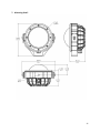
1
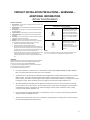
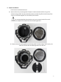
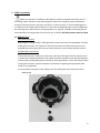
Installation Instructions BASH ENCLOSURE SERIES BASH ORIGINAL BASH GPRO BASH ALL-PRO BASH ALL-POE (INTENTIONALLY BLANK) 2 Table of Contents LIMITED WARRANTY ....................................................................................................................... 4 PRODUCT INSTALLATION PRECAUTIONS – WARNINGS – ADDITIONAL INFORMATION.................. 5 1. HARDWARE ..................................................................................................................................... 6 2. CAMERA INSTALLATION ..................................................................................................................... 7 3. CABLE CONNECTIONS: ....................................................................................................................... 9 3.1. BASH ORIGINAL ....................................................................................................................... 9 3.2. BASH GPRO .......................................................................................................................... 12 3.3. BASH ALL-PRO....................................................................................................................... 16 3.4. BASH ALL-POE ...................................................................................................................... 19 4. REPLACE LENS ASSEMBLY ................................................................................................................ 21 5. BASH INSTALLATION ...................................................................................................................... 22 6. ELECTRICAL CONDUIT GUIDELINES ..................................................................................................... 25 7. MOUNTING DETAIL......................................................................................................................... 27 3 LIMITED WARRANTY DOTWORKZ, INC. PRODUCTS DOTWORKZ SYSTEMS INC. Warrants this Product to be free from defects in material or workmanship, as follows: PRODUCT CATEGORY All Enclosures and Electronics Power Supplies Accessory Brackets PARTS One (1) Year One (1) Year One (1) Year LABOR One (1) Year One (1) Year One (1) Year During the warranty period, to repair the Product the Purchaser will deliver it to Dotworkz Systems Inc. San Diego, CA, or return the defective product, freight prepaid. The Product to be repaired is to be returned in either its original carton or a similar package presenting an equal degree of protection with a Return Materials Authorization number displayed on the outer box or packing slip. To obtain RMA # you must contact our Technical Support Team at 866-575-4689. Dotworkz Systems will return the repaired Product, freight paid. Dotworkz Systems is not obligated to provide Purchaser with a substitute unit during the warranty period or at any time. After the applicable warranty period, Purchaser must pay all labor and/or parts and shipping charges. The limited warranty stated in these product instructions is subject to all of the following terms and conditions: 1. NOTIFICATION OF CLAIMS: WARRANTY SERVICE: If Purchaser believes that the Product is defective in material or workmanship, then a written notice with an explanation of the claim shall be given promptly by Purchaser to Dotworkz Systems but all claims for warranty service must be made within the warranty period. If after investigation Dotworkz Systems determines that the reported problem was not covered by the warranty, Purchaser shall pay Dotworkz Systems for the cost of investigating the problem at its then prevailing per incident billable rate. No repair or replacement of any Product or part thereof shall extend the warranty period as to the entire Product. The specific warranty on the repaired part only shall be in effect for a period of ninety (90) days following the repair or replacement of that part or the remaining period of the Product parts warranty, whichever is greater 2. EXCLUSIVE REMEDY: ACCEPTANCE: Purchaser's exclusive remedy and Dotworkz System’s sole obligation is to supply (or pay for) all labor necessary to repair any Product found to be defective within the warranty period and to supply, at no extra charge, new or rebuilt replacements for defective parts 3. EXCEPTIONS TO LIMITED WARRANTY: Dotworkz Systems shall have no liability or obligation to Purchaser with respect to any Product requiring service during the warranty period which is subjected to any of the following: abuse, improper use, negligence, accidents, lightning damage or other acts of God (i.e., hurricanes, earthquakes), modification, failure of the end-user to follow the directions outlined in the product instructions, failure of the end-user to follow the maintenance procedures written and recommended in the product instructions and service manual, or recommended by the International Security Industry Organization. Furthermore, Dotworkz Systems shall have no liability where a schedule is specified for regular replacement, maintenance or cleaning of certain parts (based on usage) that the end-user has failed to abide to such schedule; attempted repair by non-qualified personnel; operation of the Product outside of the published environmental and electrical parameters; if such Product's original identification (trademark, serial number) markings have been defaced, altered, or removed. Dotworkz Systems excludes from warranty coverage Products sold AS IS and/or WITH ALL FAULTS and excludes used Products which have not been sold by Dotworkz Systems to the Purchaser. All software and accompanying documentation furnished with, or as part of the Product is furnished "AS IS" (i.e., without any warranty of any kind), except where expressly provided otherwise in any documentation or license agreement furnished with the Product. 4. PROOF OF PURCHASE: The purchaser’s dated bill of sale must be retained as evidence of the date of purchase and to establish warranty eligibility. DISCLAIMER OF WARRANTY EXCEPT FOR THE FOREGOING WARRANTIES, DOTWORKZ SYSTEMS HEREBY DISCLAIMS AND EXCLUDES ALL OTHER WARRANTIES, EXPRESSED OR IMPLIE D, INCLUDING, BUT NOT LIMITED TO ANY AND/OR ALL IMPLIED WARRANTIES OF MERCHANTABILITY, FITNESS FOR A PARTICULAR PURPOSE AND/OR ANY WARRANTY WITH REGARD TO ANY CLAIM OF 1NFRINGEMENT THAT MAY BE PROVIDED IN SECTION 2-312(3) OF THE UNIFORM COMMERCIAL CODE AND/OR IN ANY OTHER COMPARABLE STATE STATUTE. DOTWORKZ SYSTEMS HEREBY DISCLAIMS ANY REPRESENTATIONS OR WARRANTY THAT THE PRODUCT IS COMPATIBLE WITH ANY COMBINATION OF NON-V1DEOLARM PRODUCTS OR NON-DOTWORKZ SYSTEMS RECOMMENDED PRODUCTS THAT THE PURCHASER CHOOSES TO CONNECT TO THE PRODUCT. LIMITATION OF LIABILITY THE LIABILITY OF DOTWORKZ SYSTEMS, IF ANY, AND PURCHASER'S SOLE AND EXCLUSIVE REMEDY FOR DAMAGES FOR ANY CLAIM OF ANY KIND WH ATSOEVER, REGARDLESS OF THE LEGAL THEORY AND WHETHER ARISING IN TORT DP CONTRACT SHALL NOT BE GREATER THAN THE ACTUAL PURCHASE PRIC E OF THE PRODUCT WITH RESPECT TO WHICH SUCH CLAIM IS MADE. IN NO EVENT SHALL DOTWORKZ SYSTEMS BE LIABLE TO PURCHASER FOR ANY SPECIAL, INDIRECT, INCIDENTAL, OR CONSEQUENTIAL DAMAGES OF ANY KIND INCLUDING BUT NOT LIMITED TO COMPENSATION, REIMBURSEMENT OR DAMAGES ON ACCOUNT OF THE LOSS OF PRESENT OR PROSPECTIVE PROFITS, OR FOR ANY OTHER REASON WHATSOEVER. 4 PRODUCT INSTALLATION PRECAUTIONS – WARNINGS – ADDITIONAL INFORMATION (RETAIN THIS DOCUMENT) IMPORTANT SAFEGUARDS 1 Read Instructions - All the safety and operating instructions should be read before the unit is operated. 2 Retain Instructions -The safety and operating instructions should be retained for future reference. 3. Heed Warnings - All warnings on the unit and in the operating instructions should be adhered to. 4. Follow Instructions -All operating & user instructions should be followed. 5. Electrical Connections - Only a qualified electrician should make electrical connections. 6. Attachments - Do not use attachments not recommended by the product manufacturer as they may cause hazards 7. Cable Runs - All cable runs must be within permissible distance 8. Mounting -This unit must be properly and securely mounted to a supporting structure capable of sustaining the weight of the unit. Accordingly: a. Installation should be made by a qualified installer. b. Installation should be in compliance with local codes c. Care should be exercised to select suitable hardware to install the unit, taking into account both the composition of the mounting surface and the weight of the unit. Be sure to periodically examine the unit and the supporting structure to make sure that the integrity of the installations intact. Failure to comply with the foregoing could result in the unit separating from the support structure and falling, with resultant damages or injury to anyone or anything struck by the failing unit. CAUTION: TO REDUCE THE RISK OF ELECTRICAL SHOCK, DO NOT EXPOSE COMPONENTS TO WATER OR MOISTURE The lightning flash with an arrowhead symbol, within an equilateral triangle, is intended to alert the user to the presence of non-insulated "dangerous voltage" within the product's enclosure that may be of sufficient magnitude to constitute a risk of electric shock to persons The exclamation point within an equilateral triangle is intended to alert the user to the presence of important operating and maintenance (servicing) instructions in the literature accompanying the appliance SERVICE If the unit ever needs repair service, customer should contact Dotworkz Systems +1 (619) 224-LIVE (5483) for return authorization & shipping instructions. UNPACKING Unpack carefully. Electronic components can be damaged if improperly handled or dropped. If an item appears to have been damaged in shipment, replace it properly in its carton and notify the shipper. Be sure to save 1. The shipping carton and packaging material. They are the safest material in which to make future shipments of the equipment. 2. These Installation and Operating Instructions. For technical questions or product returns – call Dotworkz Customer Service (866-575-4689) 7:30 AM to 4:30 PM (PST). The proper technician will contact you as soon as possible. The External Nut on all electrical wire cable glands must be tightened to create a weather tight seal prior to putting BASH in service. Failure to create this seal may result in water incursion into the enclosure. This may lead to electrical shock, product failure and damage to electrical systems installed within enclosure, including but not limited to damage to camera, heater and blower circuitry, cooling circuitry and other systems installed in unit. All screws supplied with Front Ring must be tightened to create seal on enclosure. Failure to create this seal may result in water incursion into enclosure. This may lead to electrical shock, failure and damage to electrical systems installed within enclosure, including but not limited to damage to camera, heater and blower circuitry, cooling circuitry and other systems installed in unit. Do not over tighten any Screws, Stand Offs, or other fasteners on this unit. Failure to heed this warning will cause damage or failure of the BASH enclosure. Take extra care to Protect Lens of unit prior to installation, during installation and during service. Failure to protect lens will adversely affect product performance. 5 1. Hardware Ensure that all required hardware is included and recommended tools are available before beginning the installation. A. BASH Enclosure and Mounting Hardware 1 2 1 5 3 4 3 3 1 1 1 DESCRIPTION 1 1 BASH Enclosure 3/8-16 x 1”L Socket Button Head Bolt, 316 SS 3/8 Screw Clearance x 1” OD Flat Washer, 316 SS 3/8-16 Hex Lock Nut, Nylon Insert, 316 SS #6-20 Thread Forming Screw, Phillips, 316 SS 1/4-20 x 3/8”L Cap Screw, 18-8 SS 1/4 Screw Clearance Split Washer, 18-8 SS 1/4 Screw Clearance Flat Washer, 18-8 SS 1 1 ITEM 1 2 3 4 5 6 7 8 6 3 7 6 QUANTITY 3 1 1 1 1 1 1 2 1 1 1 1 8 6 3 1 1 1 B. Recommended Tools 9 10 12 11 11 15 ITEM 9 10 11 12 13 14 15 16 13 12 11 16 DESCRIPTION Hex Driver Set (a.k.a. Allen keys/Allen wrenches) 7/16” Wrench, Nut Driver or Adjustable Wrench #1 Flat Blade screw driver or smaller Wire Stripping Tool Drill Drill Bit Set RJ45 Crimping Tool RJ45 Modular Plug 14 13 12 11 QUANTITY 1 1 1 1 1 1 1 1 6 2. Camera Installation Install camera inside BASH enclosure. 2.1. Open enclosure by unscrewing 8x #6-32 captive screws located around front ring of the enclosure using a 7/64” hex key (commonly known as an Allen key/Allen wrench). Keep front ring, lens, and screws together as one assembly and set aside. It is recommended that the protective cover on the camera lens be left on until installation is complete. This reduces the risk of scratching the lens. 2.2. Remove internal mounting plate by unscrewing 4x #6-32 screws using a 7/64” hex key. Set aside the 4 screws and accompanying washers for later use. 7 2.3. Remove the camera from the enclosure or protective cover that comes with the system. In some cases, the camera will not come installed in an enclosure. Attach the camera to the mounting plate using 1/4-20 Cap Screw, split lock washer and flat washer. Torque to 28 in-lbs. Use of a screw with a nylon locking patch (instead of a split lock washer) is recommended for heavy systems in high vibration environments. Allow access to cable ports as necessary. 2.4. Loosen the two tilt adjustment screws using a 7/32” allen key. Swing the mounting bracket to the other side of the enclosure to provide clear access to the cable gland and front opening. Do not adjust tilt angle in a “partially tightened” state. Doing so can cause seizure of the bracket system beyond repair. Always loosen the tilt adjustment screws until there is a visible gap between both screw heads and the bracket prior to adjusting the tilt angle. 8 3. Cable Connections: Make sure that there is sufficient cable length to create all required connections prior to connecting cables. Add service loop (extra length) in cable runs to allow for position adjustment, change of mounting location, drip loops, and errors. In some instances, it may be advantageous to run cables prior to making cable connections. In this case, the following steps must be completed at the mounting site or short sections of required cables (i.e. “pig tails”) should be left exiting the unit and connected to the longer cable runs once the unit is installed. All cable junctions must be sealed. 3.1. BASH Original One Cable Connection: BASH Original is equipped with a cable gland that contains one hole to accommodate one cable entering the enclosure. This situation is ideal for PoE cameras and other devices that can be powered and transmit data with only one cable connection, such as USB or wireless cameras. Multiple Cable Connections: If more than one port is required, an alternative multi-port cable gland must be used to ensure a reliable seal is made around each of the cables. Dotworkz Systems has two port (PN 430-010) and three port (PN 430-009) options available for these applications. If you have multiple cables entering the enclosure, contact a Dotworkz representative regarding the appropriate Cable Gland for you application. 3.1.1.Completely unscrew the outer sealing nut of the cable gland and remove the internal rubber gland. 9 3.1.2.Pass cable through the sealing nut, wrap the split internal gland around the cable and pass the cable through the gland body into the enclosure. Connect the cable to your camera. 3.1.3.Mount the combined camera and camera mounting plate back inside the enclosure by screwing the 4x #6-32 screws and washers into the 4 mounting bosses inside the enclosure. Guide the cable(s) connected to the camera such that there is no pinching or additional stress on the cables. 10 3.1.4.Press the internal rubber gland back into the gland body. 3.1.5.Thread the sealing nut onto the gland body. Torque to 50 in-lbs. 11 3.2. BASH GPro Wireless Control and Data Download: BASH GPro is specifically designed for action cameras. Many action cameras today are equipped with wireless control and data transfer. If this is true for your camera, power is the only connection required for your system. This is the scenario covered in upcoming steps. Wired Control and Data Download: If your camera is not equipped with wireless control and data transfer, a wired connection to a controller (i.e. small LCD) must be established and used. Wired data transfer is also recommended if large file sizes are expected because file transfer is typically faster via wired connections. 3.2.1.Loosen the outer sealing nut of the cable gland to relieve pressure on the rubber gland. Do not completely unscrew the sealing nut as it would require dislodging the external microphone. 12 3.2.2.Pass your 12VDC power cable through the sealing nut and into the empty hole in the internal rubber gland, bringing the cable into the enclosure. 3.2.3.Connect the leads of the power cable to the color coded terminal block using a #1 flat head screw driver or smaller. 13 3.2.4.Connect the USB mini type B connector to the mating connector on the side of your action camera. 3.2.5.Mount the combined camera and camera mounting plate back inside the enclosure by screwing the 4x #6-32 screws and washers into the 4 mounting bosses. Bring camera cables through the bottom opening of the mounting plate to maintain necessary connections with the camera. 14 3.2.6.Place a piece of black foam or another black material over the face of the action camera to avoid reflections off of the lens. 3.2.7.Thread the sealing nut onto the gland body. Torque to 50 in-lbs. 15 3.3. BASH All-Pro IP Camera Compatible - 12VDC Powered Housing: This model is designed to work seamlessly with small PoE powered IP cameras on the market today. Inputs to this BASH system are 12VDC power and Ethernet via a Cat 5e cable. 3.3.1.Loosen the outer sealing nut of the cable gland to relive pressure on the internal rubber gland. Do not completely unscrew the sealing nut as it would require dislodging the external microphone. 3.3.2.Pass an unterminated Cat 5e cable through the sealing nut and into one of the open holes in the internal rubber gland, bringing the cable into the enclosure. Terminate an RJ45 Connector on the unterminated Cat 5e cable and connect it to the Ethernet input on the PCB (left side). 16 3.3.3.Pass a 12VDC power cable through the sealing nut and into the other empty hole in the internal rubber gland, bringing the cable into the enclosure. 3.3.4.Connect the leads of the power cable to the terminal block using a #1 phillips head screw driver or smaller. Positive/red lead goes on the left side and negative lead goes on the right. 3.3.5.Mount the combined camera and camera mounting plate back inside the enclosure by screwing the 4x #6-32 screws and washers into the 4 mounting bosses. Bring camera cables through the bottom opening of the mounting plate (if necessary) and establish connections with the camera. 17 3.3.6.Tighten the sealing nut on the cable gland body. Torque to 50 in-lbs. 18 3.4. BASH All-PoE IP Camera Compatible – PoE Powered Housing: This model is designed to work seamlessly with small PoE powered IP cameras on the market today. The input to this BASH system is PoE, which is carried on a single Cat 5e cable. Note that a PoE injector is required to power this BASH system. 3.4.1.Loosen the outer sealing nut of the cable gland to relieve pressure on the internal rubber gland. Do not completely remove the sealing nut as it would require dislodging the external microphone. 3.4.2.Pass an unterminated Cat 5e cable through the sealing nut and into the open hole in the internal rubber gland, bringing the cable into the enclosure. Terminate an RJ45 Connector on the unterminated Cat 5e cable and connect it to the PoE input on the PCB (left side). 19 3.4.3.Mount the combined camera and camera mounting plate back inside the enclosure by screwing the 4x #6-32 screws and washers into the 4 mounting bosses. Bring camera cables through the bottom opening of the mounting plate (if necessary) to establish connections with the camera. 3.4.4.Thread the sealing nut onto the gland body. Torque to 50 in-lbs. 20 Reflections off of the lens can be problematic in certain lighting conditions. It is recommended that all camera components inside the enclosure are covered with black material (i.e. foam) to minimize reflections and optimize performance. Mounting the camera closer to the lens can also help minimize reflection issues and maximize image quality. This can be achieved through the use of 4x #6-32 standoffs of varying lengths depending on the application (see images from previous section for details). 4. Replace Lens Assembly 4.1. Ensure that the front O-Ring seal is still installed and completely within the seal groove. Reinstall or make adjustments as necessary. 4.2. Re-install the Front Ring, lens, and 8x #6-32 fasteners on the front of the housing. Every screw should be started into its mating thread before tightening any of the 8 screws. Torque each of the 8 screws to 9 in-lbs. in an alternating (i.e. star) pattern. 21 5. BASH Installation Install BASH enclosure at mounting location. It is recommended that the system be mounted as high as practical for optimal viewing and capturing the most data. Imaging the camera before and after or during pan/tilt adjustments yields optimal results. 5.1. Loosen the two tilt adjustment screws until there is zero clamping force from the screws. There should be a visible gap between the screw heads and the bracket prior to adjustment. Adjust the tilt position so that camera lens is facing straight down towards the bracket and re-tighten the two side bolts. This provides tool access to the mounting hole in the bottom of the bracket. The bracket may also be completely removed for this step if preferred. 22 5.2. Using the supplied 3/8-16 bolt, washer, and hex lock nut with nylon insert, mount the enclosure in the desired location. Torque the nut to 200 in-lbs. after pan position adjustments have been made. 23 5.3. Loosen the two tilt adjustment screws until there is zero clamping force from the screws. There should be a visible gap between the screw heads and the bracket prior to adjustment. Adjust the tilt angle to the desired position and tighten the screws to 200 in-lbs. If the housing was removed from the mounting bracket in section 5.1, re-install the housing on the mounting bracket during this step, making sure that the tilt angle is optimal for the install. 5.4. Run cables from the mounted unit to the desired location where data and/or power connections can be made. This process in installation specific and may have been done prior to installing the camera (see beginning of 3. Cable Connections). Test camera functionality and control. 24 6. Electrical Conduit Guidelines The below information applies to the BASH housing when used with conduit. Follow these guidelines strictly to prevent moisture from entering the housing if conduit is used. 25 26 7. Mounting Detail 27