1
. .
Introduction
MONTERO
1984
FOREWORD
This Sk-vice Manual has been prepared with the latest
service information available at the time of publication. It is subdivided into various group categories
-and each section contains diagnosis, disassembly,
repair, and installation procedures along with complete specifications and tightening references. Use of
this manual will aid in properly performing any
servicing necessary to maintain or restore the high
levels of performance and reliability designed into
these outstanding vehicles.
WE SUPPORT
VOLUNTARY TECHNICIAN
CERTIFICATION
THROUGH
.&tsubishi Motors Corporation reserves the right to make changes in
Zesign or to make additions to or improvements in its products without
mposing any obligations upon itself to install them on its products
.reviously manufactured.
0
1983
Mitsubishi
Motors
Corporation
Printed
:
GROUP INDEX
Service Manual
l
c-,
in Japan
. , . .,......,..........
0
Lubrication
and Maintenance . . . . . . . . .
2
Front Suspension ..................
3
RearAxle:.
5
Brakes - Service and Parking .........
6
Clutch
7
Cooling ...........................
8
Electrical System ..................
9
Engine ...........................
11
Exhaust System .....................
13
Body and Frame Alignment
14
Fuel System . , . . . . . . . . . . .,. . . . . . . . .
16
Propeller Shaft and Universal Joints . . .,.
17
Rear Suspension . . . . . . . . . . . . . . . . . . .
19
Steering - Power . . . . . . . . . . . . . . ., . . .
21
Transmission -
22
Wheels and Tires. . . , . . . , , . . . . . . . . . .
23
Body and Sheet Metal
24
Heaters and Air-conditioning
25
Emission Control Systems . . . . . . . . . . .
......................
..........................
Alphabetical
Manual
Automatic
Index
..........
.,........
,.. ...........
.........
INTRODUCTION ..
i
This publication contains the essential removal,
I
installation, adjustment and maintenance procedures
for servicing all Body Styles. This information is current as of time of publication.
I
INDEX
The preceding page contains a table ofi contents
which lists the group number, group title /and symbol
of each group. The symbol is also located at the left
or right top of each page.
1
GROUP INDEX
The first page in each group has an indexI to the subjects included in that group.
I.
PAGE NUMBERS
All page numbers consist of two sets ofi digits separated by a dash. The digits preceding the dash identify the number of the group. The digits/following the
dash represent the consecutive page number :within
the group. The page numbers can be found on the
lower left or right of each page.
1
I
TEXT
i
1. This manual contains essential procedures for
removal, disassembly, inspection, reassembly and
installation. For reassembly a& installation,
L reverse the order of disassembli and removal
procedures respectively, paying attention to the
key points.
ILLUSTRATIONS
1
illustration is given in (
pertinent text for reference.
Symbol
Section
title
:
I
VICE-DRIVE
SHAFT
i
I
I
.
2-47
G---J
I
Page
number
DEijINITION OF TERMS
.
Standard Dimensions or Values
Design dimensions or values or finished dimensions
after adjustment of part.
Service Limit
The allowable limitation’of wear, bends, deformation
or other damage which restricts the use of parts due
to poor performance or insufficient strength.
I
Repair Limit
The limitation of wear, deterioration or functional
decline of parts at which correction or adjustment is I
required to maintain their performance in use.
1
SPECIAL TOOLS
Some of the special tools which appear in this Manual ,I
are either not available in the United States, or have
been modified or replaced. If the tool pictured on 1
the “Special Tools” page at the beginning of each
section has an “*“, it has been modified or replaced. i
Refer to the Mitsubishi Motors special tool catalog, i
MSSP-3ETC, check the numerical index and refer !
to the indicated page number for illustration, de- I
scription and application. If it is not listed in the
numerical ‘index,, refer to the replacemen t/inter- :I,
change list for an illustration and description of:
the new tool.
If the pictured tool has a “D”, it has been deleted, ;
and is not available in the U.S.i
,
.’
i
VEHICLE
IDENTIf~CATlON
VEHICLE
IDENTIFICATION
NUMBER
PLATE
LOCATION
The vehicle identification
number (V.I.N.) plate is located on
the left top side of 1the instrument
panel and it is visible
through the windshield.
VEHICLE
IDENTIFICATION
NUMBER
CODE CHART
All vehicle identification
numbers contain 17 digits. The vehi- ’
cle number is a code which tellscountry,
make, vehicle type,
line, etc.
JA4FJ43ElEY400001
I
I
1st
digit
2nd
digit
country
Make
Vehicle type
:
JJapan
NOTE
AMitsubishi
4Multipurpose
vehicle
WV)
F4001 lbs.
or more
with
hydraulic
brakes
\
5th
digit
6th
digit
7th
digit
8th
digit
Line
Series
Body
Engine
JMONTERO
4High
5Premium
22-door
canvastop
32-door
metaltop
E2.6 liters
(155.9
CID.)
Digit in position 9 is used for V .1.N. verification.
*Can alsobe sold in Federal States.
9th
digit
10th
digit
,Check Model
digit
yea
E1984
year
11th
digit
12th
digit
13th thru
17th digit
Plant
Transmission
Serial
number
4S-speed
49 states
5S-speed
California*
l-A/T
49 states
&A/T
California*
00001
to
99999
YNagoya
cl;
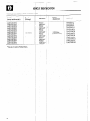
VEHICLE
.IDENTiFICATION
V. I. N.
(except serial number)
* JA4FJ42EOEY4
JA4FJ42EOEYS
JA4FJ52EUEY4
JA4FJ52EOEYS
JA4FJ43EOEY4
JA4FJ43EUEYS
JA4FJ43EUEY7
JA4FJ43EOEY8
JA4FJ53EClEY4
JA4FJ53EOEYS
JA4FJ53EOEY7
JA4FJ53EClEY8
NUMBER
I
VElfICLE
IDENTIFICATION
/
L;ST
Brand
(Package)
Destination
MONTERO
FdderaJ
California*
Federal
California*
Federal
California*
Federal
California*
Federal
California*
Federal
Califorrh”
’
.
*Can also be sold in Federal States.
T
I
T
I
i
Engine
displacement
Model code
2.555 liters
(155.9 C. I. D.)
LO42GN JLF
L042GNJLH
L042GNULF
L042GNULH
L042GVNJLF
L042GVNJLH
L042GVKJLF
L042GVKJLH
LO42GVNULF
L042GVNULH
L042GVKULF
‘L042GVKULH
‘.
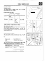
VEHICLE IDENTIFICATION
CHASSIS NUMBER
Stamping Location
The chassis number is stamped on the side of the frame
near the right rear shock absorber.
Chassis Number
Code Chart
LO4
7
2 GV
DY400001
I
Vehicle line
Engine
displacement
Body type
LO4MONTERO
22.555 liters
(155.9 C.I.D.)
G2-door
canvas-top
GV2-door
metal-top
i
Refer to 10th
thru 17th digits
of V.I.N. plate
1
VEHICLE
SAFETY CERTIFICATION
LABEL
The vehicle safety certification
label is attached to face of
left door pillar. (72W502)
This label indicates the month and year of manufacture,
Gross Vehicle Weight Rating (G.V.W.R.),
front and rear
Gross Axle Weight Rating (G.A.W.R.),
and Vehicle Identification Number (V.I.N.).
ENGINE MODEL STAMPING
The engine model number is stamped at the right front side
on the top edge of the cylinder block as shown in the following :
Engine model
Engine displacement
G54B
2.555 liters (155.9 C.I.D.)
The engine serial number is stamped near the engine model
number, and the serial number cycles, as shown below.
Engine serial number
Number
cycling
AA0201
AA0201
- - - -+ AA99991
to YY9999
LAB0001
- - - + AY9999
LBAOOOl
- - - += YY9999
5
i
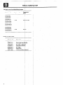
VEHICLE
1I
IDENTIFICATION
I
ENGINE
AND TRANSMISSION.MODEL
Vehicle model
Engine model
L042GNJLF
L042GNJLH
L042GNULF
L042GNULH
L042GVNJLF
L042GVNJLH
L042GVNULF
L042GVNULH
Tradsmission
mod11
I
G54B
KM 145-O-THQ
1
M42GVKJLF
L042GVKJLH
L042GVKULF
L042GVKULH
BODY COLOR
G54B
KM146
.
~
I
CODE
,Exterior code
Body color
i
Two-tone
B93B91X13
C38C19X13
H74H80X13
A R79R78X13
W44W42X13
X04X21H80
Black/Light blue (M sllic)
Black/Brown (Metal lit >
Black/Silver (Metalk id)
.Black/Red
Black/White
I
Veliet black/Silver (:“: etallic)
efi
T
6
:
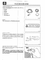
PRECAUTIONS
BEFORE SERVICE
m i
PROTECTING
THE VEHICLE
If there is a likelihood
of damaging painted or interior parts
during service operations,
protect them with suitable covers
(such as seat covers, etc.).
>’
OOY 584
Q?
REMOVAL
AND DISASSEMBLY
When checking a malfunction,
find the cause of the problem.
If it is determined
that removal and/or disassembly is necessary, perform the work by following
the procedures contained in this Service Manual.
0
0
,,’
jgi$
zzz
--
6
l
OOY 58:
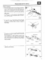
If punch marks or mating marks are made to avoid error in
assembly and facilitate the assembly work, be sure to make
them in locations which will have no detrimental
effect on
performance and/or appearances.
If an area having many parts, similar parts, and/or parts
which are symmetrical
right and left is disassembled, be sure
to arrange the parts so that they do not become mixed during
the assembly process.
1. Arrange the parts removed in the proper order.
2. Determine
which parts are to be reused and which are to
be replaced.
3. If bolts, nuts, etc., are to be replaced, be sure to use only
the exact size specified.
SPECIAL TOOLS
If other tools are substituted for the special tools to do service or repair work, there is the danger that vehicle parts might
be damaged, or the mechanic might be injured; therefore,
be sure to use the special tool whenever doing any work for
which the use of one is specified,
YOO192
FOOO17
u
;
PRECAl/TlONS
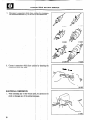
PARTS TO BE REPLACED
If any of the following parts are removed,
placed with new parts.
1. Oil seals
2. Gaskets
3. Packings
4. O-rings
5. Lock washers
6. Cotter pins
7. Self-locking
nuts
I
BEFOFE SERVICE
I
I
they must be re-i
Q’
0
2
0
0
/
PARTS
When replacing
parts, use Mitsubish .i genuin
0
-3
jarts.
D0051:
VEHICLE
WASHING
If high-pressure car-washing equipment
or I;te am &r-washing
equipment
is used to wash the vehicle, be : Is1Ire to maintain1
the spray nozzle at a distance of at least 3 00 mm 1(11.8 in.>’
from any plastic parts and all opfning par th (doors, luggagk
compartment,
sunroof, etc.).
I
mm
SERVICING
THE ELECTRICAL
SYSTEM
When servicing the electrical system, discor
cab!e terminal from the battery.
Cautibn
Before connecting
or disconnecting
the I
sure to turn off the ignition’ switch and tl
(If this is not done, there is the possibility 1
parts being-damaged.)
:
8
ect the negativ
:ativei cable, b
lighting switch
semi-conducta
e:
(in.)
SOOO5~
PRECAUTIONS
BEFORE SERVICE
WIRING
HARNESES
1. Secure the wiring harnesses by using clamps so that there
is no slack. However, for any harness which passes to the
engine or other vibrating parts of the vehicle;allow
some
slack within a range that does not allow the engine vibrations to cause the harness to come into contact with any
of the surrounding
parts. Then secure the harness. by
using a clamp.
In addition, if a mounting
indication
mark (yellow tape)
is on a harness, secure the indication
mark in the specified location. (C 1638 1)
2. If any section of a wiring harness contacts the edge
of a part, or a corner, wrap the section of the harness
with tape or something
similar in order to protect it
from damage.
F1617
3. When using a circuit tester to perform continuity
or voltage checks on connector terminals, insert the test probe
from the harness side.
If the connector is a sealed connector,
insert the test
probe into the hole in the rubber cap for the electrical
wires, being careful not to damage the wire insulation.
Continue to insert the test probe until it makes contact
with the terminal.
Sealed
I
4. When disconnecting
a connector,
connector, not the harness.
16YQ5
16YQ52
be sure to pull only the
Correct
I
connector
Incorrect
1
I
n;
PRECfiUTIONS
BEFORE SERVICE
I
5. Disconnect connectors which have c :hes by pressing in
the direction indicated by the arrows the illustration.
Cl6384
Y1634:
6. Connect connectors which have catclles; by inserting the
connectors until they snap.
ELECTRICAL
COMPCiNENTS
1. When installing any of the vehicle part be careful no1
pinch or damage any of the wiring han sses.
I
10
Cl6382
..
PRECAUTIONS
2.
BEFORE SERVICE
Sensors, relays, etc., are sensitive to strong impacts.
Handle them with care so that they are not dropped or,
mishandled.
OOY58E
3.
The electronic parts used for relays, etc., are sensitive to
heat. If any service which causes a temperature
of 80°C
(176’F)
or more is performed,
remove the part or parts
in question before carrying out the service,
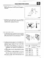
FUSES AND FUSIBLE
LINKS
1. If a blown-out fuse is to be replaced, be sure to use only
a fuse of the specified capacity. If a fuse of a capacity
larger than that specified is used, parts may be damaged
and the circuit may not be protected adequately.
15A
2.
If additional
optional equipment
is to be installed in the
vehicle, follow the procedure listed in the appropriate
instruction
manual;
however, be sure to pay careful
attention to the following points:
(1) In order to avoid overloading
the wiring, take the
electrical current load of the optional equipment into
consideration,
and determine
the appropriate
wire
size.
(2) Where possible, route the wiring through the existing
harnesses.
(3) If an ammeter
or similar instrument
is to be connected to a live-wire circuit, use tape to protect the
wire, use. a clamp to secure the wire, and make sure
that there is no contact with any other parts.
(4) Be sure to provide a fuse for the load circuit of the
optional equipment.
.
OOY 582
Nominal
size
SAE
gauge
No.
Permissible current
In engine
compartment
AWG 22 0.5 mm2 AWG 20 7A
0.85 mm2 AWG 18 9A
1.25 mm2 AWG 16 12A
2.0 mm2
AWG 14 16A
3.0 mm2
AWG 12 21A
5.0 mm2 AWG 10 31A
0.3 mm2
Other areas
SA
13A
17A
22A
30A
40A
54A
11
I
II
PRECljUTlONS
1
I
BEFORE SERVICE
TUBES AND OTHER RUBBER PARTS
Be careful to avoid spilling any gasoline, oil, etc., because if it
adheres to any tubes or other rubber parts, they might be adversely affected.
OOY 58f
LUBRICANTS
In accordance with the instructions
in this Service Manual
apply the specified lubricants in the specified locations dur:
ing assembly and installation.
F 00028
BRAKE
.
FLUID
Be careful to avoid spilling any brake flui .q, because if it ;ad
heres to the vehicle body, the paint coat nIi{ $it be discolor- et
DOING SERVICE
MECHANICS
WORK
IN GROUPS
C .TWO OR MO1
If the service work is to be done by two
working together,
all the; mechanics inv
safety into consideration
while they work.
12
more mechan
ved should ta
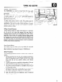
TOWING AND HOISTING
TOWING AND HOISTING
The MONTERO
can only be towed from the front with
conventional
sling-type
equipment
and tow chain &th
grab hooks.
If a vehicle is towed from the rear, use a tow dolly.
A lumber spacer (4” x 4” x 55” wood beam) should be
placed forward of under guard and under towing hook/
shipping tie down hook.
Then, attach J-hook to the lower arm.
A safety chain system must be used. This system must be
completely
independent
of the primary lifting and’ towing
attachment.
Care must be taken in the installation
of safety
chains to insure they do not cause damage to bumper,
painted surfaces or lights.
Lifting-Ground
Clearance
Towed vehicle should be raised until wheels are a minimum
of 10 cm (4 in.) from the ground. Be sure there is
adequate ground clearance at the opposite end of the vehicle,
especially when towing over rough terrain or when crossing
sharp rises such as curbs. If necessary, ground clearance can
be increased by removing the wheels from the lifted end of
the disabled vehicle and carrying the lifted end closer, to the
ground. A 20 cm (8 in.) ground clearance must be maintained
between brake drums and ground.
Front Towing Pickup
The vehicle may be towed on its rear wheels for extended
distances, provided the parking brake is released.
Make certain the transmission remains in “NEUTRAL”.
Safety Precautions
The following precautions should be taken when towing the
vehicle.
1. Remove exhaust tips and any other optional equipment,
that interface with the towing sling. Padding (heavy shop
towel or carpeting) should be placed between the towing
sling cross bar and any painted surfaces, and bumper
surfaces.
2. A safety chain system completely
independent
of the primary lifting and towing attachment
must be used.
3. Any loose or protruding parts of damaged vehicle such as
hoods, doors, fenders, trim, etc., should be secured prior
to moving the vehicle.
4. Operator should refrain from going under a vehicle unless
the vehicle is adequately supported by safety stands.
5. Never allow passengers to ride in a towed vehicle.
6. State and local rules and regulations
must be followed
when towing a vehicle.
13
TOWING AND HOISTING
HOISTING
Post Type
Special care should be taken when raising the vehicle on a
frame contact type hoist. The hoist. must be equipped with
the proper adapters in order to support the vehicle at the
proper locations. (See next page)
Conventional hydraulic hoists may be used after determining
that the adapter plates will make firm contact with the side
frame.
Floor Jack
A regular floor jack may be used under the front crossmember or rear axle housing.
Caution
1. A floor jack must never be used on any ‘part of the
underbody.
2. Do not attempt to raise one entire side of the vehicle by
pIacing a jack midway between front and rear wheels.
This practice may result in permalient damage to the
body.
Emergency Jacking
Jack receptacles are located at the front crossmember and
rear axle housing to accept the jack supplied with the vehicle
for emergency road service. Always block the opposite
wheels and jack only on a level surface.
14
.
TOWING AND HOISTING
Frame Contact
Support
Locations
NOTE
The locations
same as those
shown
in the
Lifting
of the support
point
shown
as Section
of the twin
post hoist
or sissors
jack
illustration
(OOW554)
below.
and Jacking
Support
A-A are the
(emergency)
Locations
1. :::.~:~?.i~.:.f.~::
Twinposthoist
m
Floorjack
0
Frame
contact
or jack
(jack
supplied
with
the vehicle)
on hoist
oow554
15
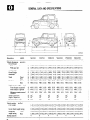
GENERAL
DATA AND SPECIFICATIONS
OOW556
Description
Vehicle dimensions
mm (in.)
Overall length
Without spare tire
With spare tire
Overall width
Overall height
Wheelbase
Tread
Front
Rear
Overhang
Front Rear
Height at curb weight’
(wt.)
Front bumper to ground
Rear bumper to ground ’
Minimum running ground
clearance
Angle of approach
Angle of departure _
Ramp breakover angle
Vehicle weights
Curb weight
VNJLF/H
VKJLF/H
@ 3,930 (154.7)
0
3,995 (157.3)
0
1,680 ( 66.1)
@ 1,760 ( 69.3)
@ 2,350( 92.5)
8
1,400( 55.1)
a
1,375( 54.1)
‘@ 745 ( 29,3)
8 -900 ( 35.4)
3,930 (154.7)
3,995 (157.3)
1,680 ( 66.1)
1,760 ( 69.3)
2,350 ( 92.5)
1,400( ,551l)
1,375( 54.1)
745 ( 29.3)
900 ( 35.4)
3,930 (154.7)
3,995 (157.3)
1,680 ( 66.1)
1,800 ( 70.9)
2,350( 92.5)
1,400( 55.1)
1,375( 54.1)
745 ( 29.3)
900 ( 35.4)
3,930 (154.7) 3,930
3,995 (157.3) 3,995
1,680 ( 66.1) 1,680
1,800 ( 70.9) 1,800
2,350 ( 92.5) 2,350
1,400 ( 55.1) 1,400
1,375( 54.1).1,375(
745 ( 29.3)
745 (
900 ( 35.4)
900 (
@
.o
@
480( 18.9)
440 ( 17.3)
210 ( 8.3)
480( 18.9)
440 ( 17.3)
2iO(
8.3)
480( 18.9)
440 ( 17.3)
210(
8.3)
480 ( 18.9)
440 ( 17.3)
210 ( 8.3)
480 ( 18.9)
440 ( 17.3)
210 ( 8.3)
480 ( 18.9)
440 ( 17.3)
210 ( 8.3)
0’
@
38’
30”
0
21”
3b
3o”
21”
38”
3o”
21”
38O
30”
21”
38”
30”
21”
38’
30”
21”
NJLF/H
VNULF/H
(154.7)
(157.3)
( 66.1)
( 70.9)
( 92.5)
( 55.1)
54.1)
29.3)
35.4)
VKULF/H
3,930 (154.7)
3,995 (157.3)
1,680 ( 66.1)
1,800 ( 70.9)
2,350( 92.5)
1,400( 55.1)
1,375( 54.1)
745 ( 29.3)
800 ( 35.4)
kg (lbs.)
Gross vehicle weight rating
Gross axle
Front
weight rating
Rear
Seating capacity
16
NULF/H
LO42G
1,411
1,412
1,910
1,000
1,450
4
(3,111)/1,428
(3,113)
,429
(4,210) I ,910
(2,205)
,000
(3,197)
,450
4
(3,148)/1,441
(3,150) 1,442
(4,210) 1,910
(2,205) 1,000
(3,197) .1,450
4
(3,177)/l
(3,179)
(4,210)
(2,205)
(3,197)
,456
1,457
1,910
1,000
1,450
4
(3,210)/1,462
(3,212) 1,463
(4,210) 1,910
(2,205) 1,000
(3,197) 1,450
4
(3,223)/1,477
(3,225) 1,478
(4,210) 1,910
(2,205) 1,000
(3,197) 1,450
4
(3,256)/
(3,258)
(4,210)
(2,205)
(3,197)
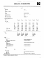
GENERAL DATA AND SPECIFICATIONS
Description
LO42G
NJLF/H
Engine
Model No.
Type
Number of cylinders
Bore
Stroke
Piston displacement
Compression ratio
Firing order
Basic ignition timing
Gear ratio
Transmission
Transfer case
1st
2nd
3rd
4th
5th
Reverse
High
Low
Final ring gear ratio
Clutch
Type
Chassis
Tire size
Front suspension
Type
Spring constant (Wheel position)
Rear suspension
Type
Spring constant
At load of 1,OOO-2,500 N
(220-551 lbs.)
At load of 4,670-8,870 N
(1,030-1,955 lbs.)
Brakes
Front
Type
Rear
Power steering
Gear type
Gear ratio
Fuel tank capacity
ViULF/H
VNULF/H
VKULF/H
G54B
In-line OHC
4
9i.l mm (3.59 in.)
98.0 mm (3.86 in.)
2,555 cm3 (155.9 CID)
8.2
l-3-4-2
7”BTDC + 2”
-3
Transmission & transfer case
Model No.
Type
VNJLF/H
NULFIH
KM145
S-speed
manual
KM145
5-speed
manual
KM145
5-speed
manual
KM146
3-speed
automatic
KM145
5-speed
manual
KM146
3-speed
automatic
3.740
2.136
1.360
1 .ooo
0.856
3.578
1.ooo
1.944
4.625
4.875*
3.740,
2.136
1.360
1.ooo
0.856
3.578
1 .ooo
1.944
4.625
4.875”
3.740
2.136
1.360
1.000
0.856
3.578
1 .ooo
1.944
4.625
4.875*
2.745
1.543
1 .ooo
2.214
1.ooo
1.944
4.222
4.625*
3.740
2.136
1.360
1.ooo
0.856
3.578
1.ooo
1.944
4.625
4.875”
2.745
1.543
1.OOO
Dry single
disc &
diaphragm
spring
Dry single
disc &
diaphragm
spring
Dry single
disc &
diaphragm
spring
-
Dry single
disc &
diaphragm
spring
2.214
1.ooo
1.944
4.222
4.625*
‘,
-
215SR15
Wishbone compression type
22 N/mm (123 lbs./in.)
Asymmetrical
semi-elliptic leaf spring
24 N/mm (134 lbs ./in.)
56 N/mm (3 14 Ibs./in.)
Disc
Drum
(Leading and trailing)
Integral type (Recirculating ball nut).
16.4
60 liters (15.9 U.S. ga.lJ13.2 Imp. gal.)
*Optional for Federal (not available in California).
17
CONVlRSlON
CAPACITY
CONVERSION
TABLE
TABLE
U.S. gal.
Imperial gal.
Imperial gal.
l/4
l/2
314
115
5-314
318
518
SI
z-1,4
6-l/2
314
6-314
6-314
7
7-l/4
7-l/2
7-314
:-l/4
l-1/2
l-3/4
l-314
2
2-l/4
Imperial gal.
E-l,2
16
16-l/2
16-314
12-l/2
13
13-l/4
13-314
14
17
17-l/2
k/2
14-l/4
14-l/2
15
15-l/2
15-3 14
16-l/4
L/2
i
%-l/2
33-l/4
3-l/2
3-314
2-l/2
2-314
3
3
i-:\:
9-
i-1,4
4-l/2
4-3/4
3-l/4
3-l/2
3-314
4
9-l/4
9-l/4
9-l/2
9-314
4-l/4
4-l/4
10
:::;:
:i-:R
10:1/2
5
S-114
S-112
5-314
U.S. gal.
16-314
17
8-l/4
17-l/2
E-1,2
22
22-l/2
z-1,2
::-l/4
18-314
19-l/4
19-l/2
El,2
z-l/2
25
25-l/2
z-l/2
20-3 14
21-l/4
21-314
I
E-l,2
5
z-1,4
6-l/2
6-314
CAPACITY
Gallons
5-l/4
5-l/2
5-l/2
CONVERSION
0
U.S. GALLONS
1
z-1,2
28
29
30
10-314
1l-1/4
1l-3/4
12
2
;;-;u$
2.5
TO I TERS
3
4
5
6
7
8
9
Liters
18
LO
37.854
3’:
40
75.708
113.56
151.42
2
227.12
189.27
ii
264.98
302.83
90
340.69
3.7854
41.640
79.494
117.35
155.20
7.5708
45.425
83.279
121.13
158.99
11.3560
49.210
87.064
124.92
162.77
15.1420
52.996
90.850
128.70
166.56
18.9270
56.781
94.635
132.49
170.34
22.7 120
60.567
98.421
136.27
174.13
26.4980
64.352
102.210
140.06
177.91
30.2830
68.137
105.990
143.85
181.70
34.0690
71.923
109.781
147.63
185.49
193.06
230.91
268.76
306.62
344.47
196.84
234.70
272.55
3 10.40
348.26
200.63
238.48
276.33
314.19
352.04
204.41
242.27
280.12
317.97
355.83
208.20
246.05
283.91
321.76
359.61
211.98
249.84
287.69
325.55
363.40
215.77
253.62
291.48
329.33
367.18
219.55
257.41
295.26
333.12
370.97
223;.34
261.19
299.05
336.90
374.76
CONVERSION
DIMENSION
AND TEMPERATURE
Inches
Millimeters
CONVERSION
T
(decimals)
(fraction)
l/64
l/32
3164
l/16
5164
3132
l/64
l/8
9164
S/32
11164
3116
13164
l/32
15164
114
11164
9132
19164
5116
21164
11/32
23164
318
25164
13132
27164
7116
29164
15132
31164
112
33164
17132
35164
9116
31164
19132
39164
518
41164
21132
43164
11/16
45164
23132
41164
314
49164
25132
51164
13/16
53164
21132
55164
718
51164
29132
59164
15/16
61164
31132
63164
.a15625
.03125
.046875
.0625
.078125
.09375
.109375
.125
.140625
.15625
.171875
.1875
.203125
.21875
.234375
.25
.265625
.28125
.296875
.3125
.328125
.34375
.359375
,375
.390625
.40625
.421875
.4315
.453125
.46875
.484375
.5
.515625
.53125
.546875
.5625
.578125
.59315
.609375
,625
.640625
.65625
.671875
.6815
.703125
.71875
.734375
.75
.765625
.78125
.796875
.8125
.828125
.84375
.859375
.875
.890625
.90625
.921875
.9375
.953125
.96875
.984375
.3969
.7937
1.1906
1.5875
1.9844
2.3812
2.7781
3.1750
3.5719
3.9687
4.3656
4.7625
5.1594
5.5562
5.9531
6.3500
6.7469
7.1437
7.5406
1.9375
8.3344
8.7312
9.1281
9.5250
9.9219
10.3187
10.7156
11.1125
11.5094
11.9062
12.3031
12.7000
13.0969
13.4937
13.8906
14.2875
14.6844
15.0812
15.4781
15.8750
16.2719
16.6687
17.0656
17.4625
17.8594
18.2562
18.6531
19.0500
19.4469
19.8437
20.2406
20.6375
21.0344
21.4312
21.8281
22.2250
22.6219
23.0187
23.4156
23.8125
24.2094
24.6062
25.0031
i
4
:
7
;
10
11
12
13
14
15
16
17
18
19
20
21
22
23
24
25
26
27
CHART
-
Inches
to millimeters
Inches
mm
.OOOl
.0002
.0003
.0004
.0005
.0006
.0007
.0008
.0009
.OOl
.002
.003
.004
.005
.006
.007
.008
.009
.Ol
.02
.03
.04
.05
.06
.07
.08
.09
.I
.2
.3
.4
.5
.6
:;
.9
1
TABLE
.00254
.00508
.00762
.01016
.01270
.01524
.01778
.02032
.02286
.0254
.0508
.0762
.1016
.1270
.1524
.1778
.2032
.2286
.254
.508
.I62
1.016
1.270
1.524
1.778
2.032
2.286
2.54
5.08
7.62
10.16
12.70
15.24
17.78
20.32
22.86
25.4
50.8
76.2
101.6
127.0
152.4
177.8
203.2
228.6
254.0
279.4
304.8
330.2
355.6
381.0
406.4
431.8
451.2
482.6
508.0
533.4
558.8
584.2
609.6
635.0
660.4
690.6
-r
Millimeters
mm
0.001
0.002
0.003
0.004
0.005
0.006
0.007
0.008
0.009
0.01
0.02
0.03
0.04
0.05
0.06
0.07
0.08
0.09
0.1
0.2
0.3
0.4
::2
0.7
0.8
0.9
1
2
3
4
5
6
;
9
10
11
12
13
14
15
16
17
18
19
20
21
22
23
24
25
26
21
28
29
30
31
32
33
34
35
36
Fahrenheit
to inches
Inches
.000039
.000079
.000118
.000157
.000197
.000236
000276
.000315
.000354
.00039
.00079
.00118
.00157
.00197
.00236
.00276
.00315
.00354
.00394
.00787
.01181
.01575
.01969
.02362
.02756
.03150
.03543
.03937
.07874
.11811
.15748
.19685
.23622
.27559
.31496
.35433
.39370
.43307
.47244
.51181
.55118
.59055
.62992
.66929
.70866
.74803
.78740
.82617
.86614
.90551
.94488
.98425
1.02362
1.06299
1.10236
1.14173
1.18110
1.22047
1.25984
1.29921
1.33858
1.37795
1.41732
“F
-20
-15
-10
-5
I
f
:
5
10
15
20
25
30
35
40
45
50
55
60
65
70
75
80
85
90
95
100
105
110
115
120
125
130
135
140
145
150
155
160
165
170
175
180
185
190
195
200
205
210
212
215
220
225
230
235
240
245
250
255
260
265
& Celsius
“C
-28.9
-26.1
-23.3
-20.6
-17.8
-17.2
-16.7
-16.1
-15.6
-15.0
-12.2
-9.4
-6.7
-3.9
-1.1
1.7
4.4
1.2
10.0
12.8
15.6
18.3
21.1
23.9
26.1
29.4
32.2
35.0
37.8
40.6
43.3
46.1
48.9
51.7
54.4
57.2
60.0
62.8
65.6
68.3
71.1
73.9
16.7
79.4
82.2
85.0
87.8
90.6
93.3
96.1
98.9
100.0
101.7
104.4
107.2
110.0
112.8
115.6
118.3
121.1
123.9
126.6
129.4
“C
-30
-28
-26
-24
-22
-20
-18
-16
-14
-12
-10
1;
-4
-2
0
:
6
8
10
12
14
16
18
20
22
24
26
28
30
32
34
36
38
40
42
44
46
48
50
52
54
56
58
60
fi
66
68
70
ii
85
90
95
100
105
110
115
120
125
130
“F
-22
-18.4
-14.8
-11.2
-7.6
-4
-0.4
3.2
5.8
10.4
14
11.6
21.2
24.8
28.4
32
35.6
39.2
42.8
46.4
50
53.6
57.2
60.8
64.4
68
71.6
75.2
78.8
82.4
86
89.6
93.2
96.8
100.4
104
107.6
112.2
114.8
118.4
122
125.6
129.2
132.8
136.4
140
143.6
147.2
150.8
154.4
158
167
176
185
194
203
212
221
230
239
248
257
266
19
CON\
ut
ENGLISH
AND SI METRIC
Cubic Centimeters
MEASURE
to Inches:
When changing cubic centimeters to cubic inc; es,
multiply cubic centimeters times .06 1 to obtain cxl1oic
inches, (C.C. x .061 = Cubic Inches).
Cubic Inches to Centimeters:
When changing cubic inches to cubic centime :te5
multiply cubic inches times 16.39 ,to obtain c:dlJic
centimeters, (Cubic Inches x 16.39 = C.C.).
Liters to Cubic Inches:
When changing liters to cubic inches, multiply !Ii 51
ers
times 61.02 to obtain cubic inches,,. (Liters x 61. I1!.=
Cubic Inches).
Pounds to Kilograms:
When changing pounds to kilograms, multiply pounds
times .4536 to obtain kilograms, (Pounds x .4536 =
Kilograms).
Kilograms
to Pounds:
When changing kilograms to pounds, multiply kilograms times 2.2046 to obtain pounds, (Kilograms x
2.2046 = Pounds).
Pounds to Newtons:
When changing pounds to newtons, multiply pounds
times 4.4482 to obtain newtons, (Pounds x 4.4482 =
Newtons)
Newtons to Pounds:
Cubic Inches to Liters:
When changing cubic inches to liters, multiply cI.1bit
inches times -01639 to obtain liters, (Cubic Inch162 SX
.O1639 = Liters).
When changing newtons to pounds, multiply newtons
times .2248 to obtain pounds, (Newtons x’ .2248 =
Pounds).
Foot-pounds
Cubic Centimeters
to Liters:
.
When changing cubic centimeters to liters, divid by
1,000 simply by moving. the decimal point 1 ree
figures to the left.
When changing foot-pounds
to newton-meters,
multiply foot-pound times 1.3558 to newton-meters,
(Foot-pound x 1.3558 = Newton-meters).
Newton-meters
Liters to Cubic Centimeters:
to Newton-meters:
to Foot-pounds:
When changing liters to cubic centimeters, move :he
decimal point three figures to the right.
When changing newton-meters, to foot-pounds,
multiply newton-meters times .7376 to. foot-pounds,
(Newton-meters x .7376 = Foot-pounds).
Miles‘to
Pounds Per Square Inch(psi)
Kilometers:
When changing miles to kilometers, multiply I les
times 1.609 to obtain kilometers, (Miles x 1.6~ I=
Kilometers).
Kilometers
to Miles:
’
When changing kilometers to miles, multiply ki lometers times .6214 to obtain miles, (Kilometc : six
.6214 = Miles).
20
to Kilopascals:
When changing pounds per square inch(psi) to kilopascals, multiply pounds per square inch times 6.895
to kilopascals, (Pounds Per Square Inch(psi) x 6.895
= Kilopascals.).
Kolopascals
to Pounds Per Square Inch(psi):
When changing kilopascals to pounds per square
inch(psi), multiply kilopascals times .1450 to pounds
per. square inch(psi), (Kilopascals x .1450 = Pounds
Per Square Inch(psi)).
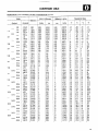
TIGHTENING
PT l/4
PT 318
Taper thread for dry sealed pipes
(size)
NPTF l/16
NPTF l/8
NPTF l/4
Remarks
Torque Nm (ft. lbs.)
Description
Thread for general purposes
(size x pitch) (mm)
6x 1.0
8 x 1.25
10 x 1.25
12 x 1.25
14 x 1.5
16 x 1.5
18 x 1.5
20 x 1.5
22 x 1.5
24 x 1.5
Taper thread for pipes (size)
PT l/8
c
13
TORQUE
Head mark
3.0 to 3.9
7.9 to 12
16 to 23
29 to 43
48 to 70
67 to 100
100 to 150
150 to 190
200 to 260
260 to 320
Head mark
@
(2.2 to 2.9)
4.9 to 7.8
(5.8 to 8.7)
13 to 19
(12 to 17)
27 to 39
(21 to 32)
47 to 72
(35 to 52)
77 to 110
(51 to 77)
130 to 160
(74 to 110)
180 to 230
(110 to 140) 160 to 320
(150 to 190) 340 to 430
(190 to 240) 420 to 550
7.9 to 12
16 to. 19
19 to 30
34 to 45
39 to 54
58 to 73
4.9 to 7.8
7.9 to 12
7.9 to 12
16 to 19
19 to 30
34 to 45
t”,
to
to
to
(3.6 to 5.8)
(9.4 to 14)
(20 to 29)
(35 to 53)
(57 to 85)
(90 to 120)
(130 to 170)
(190 to 240)
(250 to 320)
(310 to 410)
Internal thread: Aluminum
Internal thread: Cast iron
gt’“l”4:’
(14
(25
(29
(43
@
22)
33)
40)
54)
Internal
Internal
Internal
Internal
thread:
thread:
thread:
thread:
Aluminum
Cast iron
Aluminum
Cast iron
(14 to 22)
(25 to 33)
Internal
Internal
Internal
Internal
Internal
Internal
thread:
thread:
thread:
thread:
thread:
thread:
Aluminum
Cast iron
Aluminum
Cast iron
Aluminum
Cast iron
21