1
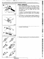
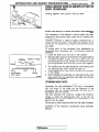
x
NrJDAA-A
GROUP INDEX
Service Manual
Introduction and
Master Troubleshooting
MONTCRO
......*....*...*..
Lubrication and Maintenance
. .. .. .. .. m.
Front Suspension .. .. ... . ... . ... . ... .. .. .. .. . . y
1989 : Volume
1
FOREWORD
This Service Manual has been prepared with the
latest service information
available at the time of
publication.
It is subdivided
into various group
categories
and each section contains diagnosis,
disassembly,
repair, and installation
procedures
along with complete specifications
and tightening
references.
Use of this manual will aid in properly
performing
any servicing necessary to maintain or
restore the high levels of performance
and reliability
designed into these outstanding
vehicles.
Rear Axle *.......*.......*................a.....*..
Srakes-
Service
Parking
. .. .. .. .. .. .. .. .. .. .. .. .. .. .. &
Clutch ................................................
Hi
Cooling
.............................................
w
Engine ...............................................
m
Intake and Exhaust ,.......*..........*......
ml
Fuel System . . .. .. .. .. .. .. ... . ... . .. . ... .. .. .. ... . mE
Propeller Shaft and Universal
Joint
Rear Suspension
Power Steering
A
m
.. .. . ... m;
.. .. .. .. . ... . ... . ... .. .. . ... .. mt
... . ..a*........................ m
.
Transmission - fity$tic
n
4liP
WESUPPORT
VOLUNTARY
TECHNICIAN
CE,TT,flCA~ONMROUGH
Wheels and Tires .............................
FP
Body ..................................................
m
Heater and Air Conditioning
Inr
Mitsubishi
Motors
corporation
reserves
the right to make changes
in
design or to make additions
to or improvements
in its products
without
imposing
any obligations
upon itself to install them on its products
previously
manufactured.
Q 198’8
Mitsubishi
Motors
Corporation
Printed
........... p!’
Emission Control Systems .............. &!!!!
MITSUBISHI
MOlUR SALES OF AMERICR
. .. .. .. ... ... &!a
in Japan
NOTE
For Electrical refer to .._
Volume-2 “Electrical”
~~~~
-~-L
2
-.._i._--
-
--em._.
INTRODUCTION AND MASTER TROUBLESHOOTING - How To Use This Manual
HOW TO USE THIS MANUAL
CONTENTS
The preceding
page contains the GROUP
which lists the group title and group number.
INDEX
PAGE NUMBERS
All page numbers
consist of two sets of digits
separated by a dash. The digits preceding the dash
identify the number of the group. The digits following the dash represent
the consecutive
page
number within the group. The page numbers can
be found on the top left or right of each page.
gg$I!
NWS&Wl g-
LIMIT
Shows the standard for judging the quality of a part
or assembly
on inspection
and means the maximum or minimum value within which the part or
assembly must be-kept functionally
or in strength.
It is a value established
outside the range of
standard value.
TEXT
Unless otherwise specified, each service procedure
covers all models.
Procedures
covering specific
models are identified by the model codes, or similar
designation
(engine type, transmission
type, etc.).
A description
of these designations
is covered in
this unit under “VEHICLE IDENTIFICATION”.
TROUBLESHOOTING
Troubleshootings
are classified into master troubleshooting and group troubleshooting
and located as
follows:
The master troubleshooting
is prepared when the
trouble symptom relates to two or more groups and
given in MASTER TROUBLESHOOTING.
The group troubleshooting
guide is prepared for
causes of problems related to that individual group
only; a troubleshooting
guide is prepared for each
appropriate group.
incidental operation
rformed
before re-
Removal steps : The numbers before part names b
correspond
to numbers in the illustration and indicate the order of
removal.
Disassemblv steos : The numbers
before
oat-t
names co&pond
to num6&
in the illustration, and indicate
the order of’disassembly.
I
---I--
Installation
steps : This is provided if installation
cannot be made in the reverse
order of “Removal steps”; omitted if installation in the reverse
order of “Removal
steps”
is
possible.
Reassembly steps : This is provided if reassembly
cannot be made in the reverse
order of “Disassembly
steps”:
omitted if reassembly
in the
reverse order
SERVICE PROCEDURES
The sewice steps are arranged in numerical order
and attentions to be paid in performing vehicle service are described in detail in SERVICE POINTS.
DEFINITION OF TERMS
STANDARD VALUE
indicates the value used as the standard for judging
the quality of a part or assembly on inspection or the
value to which the part or assembly is corrected and
adjusted. It is given by tolerance.
The following
abbreviations
are used
in this manual
for classification
of model
~!
E-m+
types.
M/T : Indicates the manual transmission,
or models equipped
with the manual transmission.
A/T : Indicates the automatic
transmission,
or models equipped with the automatic transmission.
F.B.C. : Indicates the feed back carburetor,
or engines equipped
with the feed back carburetor.
M.P.I. : Indicates the multi-point
injection,
or engines equipped
witkthe
multi-point
injection.
2.6 L Engine : Indicates the 2.6 liters (155.9 cuin.) engine, or a model equipped with such an engine.
3.0 L Engine : Indicates the 3.0 liters (181.4 cu.in.) engine, or a model equipped with such an engine.
g&is
:
g ’
sar-=
m.
Ez
INTRODUCTION AND MASTER TROUBLESHOOTING - How To Use This Manual
Page number
Group title
t
7-io
COOLING
Section title
- Thedostat
I
THERML vrra-r
. -.
REMOVAL
AND
INSTALLATlON
Indicates tightening
torque
I
Repair
shown.
kit or set parts are
fOnlv verv freouentlv
-
This number corresponds to
the number
in “Removal
steps”, “Disassembly
steps”, “Installation
steps”
or “Reassembly steps”.
1. Connection of enginecoolant
temperature
syitch connector
(Vehicles with an air condition-
+ee
3. Water outlet
4. Water outlet
5 Thermostat
fitting
fitting
gasket
I
L
SERVICE
S.
POINTS
INSTALIATION
Install
the thermostat
caution
The thermostat
ensure
OF INSTALLATIONOF THERMOSTAT
that
to the
intake
manifold as illustrated.
Range tits over the
the thermostat
is not installed
manifold
seat;
at an angle.
An explanation
of procedures,
regarding removal, installation.
and reassembly.
notes, etc.
disassembly
3
,,
i
-
4
./a
.*,
,., L
INTRODUCTION AND MASTER TROUBLESHOOTING -Vehicle Identification
VEHICLE IDENTIFICATION
VEHICLE IDENTIFICATION NUMBER LOCATIONm..
The vehicle identification
number (V.I.N.) is located
attached to the left top side of the instrument
panel.
on a plate
--
VEHICLE IDENTIFICATION CODE CHART PLATE
All vehicle identification
number is a code which
T
-
3rd
digit
Vehicle
type
4
Multipurpose
vehicle
(MW
7Truck
1
Ibs. and
with
hydraulic
brakes
G50016000
Ibs. and
with
hydraulic
brakes
t
numbers contain 17 digits. The ve!h%
tells country, make, vehicle type, etc.
I---
\
6th
digit
7th
digit
Price
class
Body
4High
5Premium
33-door
metaltopor
van
8th
digit
9th
digit
/ 10th
digit
1 Engine 1 zi$c”
/ Efe’
cu.in.1
S3.0liters
(181.4
cuin.)
1
3
12th thru
17th digit
I-Plant
Serial
number
JNagoya
-3
000001
to
999999
9
X
NOTE
““Check digit” means a single number or letter)( used to verify the accuracy of transcription
number.
( TSB Revision
11th
digit
!
of vehicle identification
-.
INTRODUCTION AND MASTER TROUBLESHOOTING
VEHICLE
FEDERAL
\DENTlFlCATlON
NUMBER
- Vehicle
Identification
5
LIST
NWCG
VIN (except sequence number)
Brand
q KJ
JA7FJ43E
JA7FJ43S 0 KJ
JA7FJ43S 0 KJ
JA7FJ53S Cl KJ
JA4GJ41 S 17 KJ
JA4GJ41 S 0 KJ
JA4GJSlSCiKJ
MITSUBISHI
MONTERO
\
Engine displacement
Model code
2.555 liters (155.9 cu.in.)
L042GTNJLF
2.972 liters (181.4 cub.)
L141GTNJLF
L141 GTRJLF
L141 GTRULF
Ll46GVMNJLF
L146GVMRJLF
L146GWMRULF
Engine displacement
Model code
L
CALIFORNIA
(Can also be sold in Federal states.]
VIN (except sequence number)
JA7FJ43E 0 KJ
Brand
I
JA7FJ43S q KJ
JA7FJ43S q KJ
JA7FJ53S 0 KJ
JA4GJ41 S 0 KJ
JA4GJ41 S q KJ
JA4GJ51 S Cl KJ
I
MITSUBISHI
MONTERO
2.555 liters (155.9 cu.in.)
2.972 liters (181.4 win.)
I
L042GTNJLH
.~
L141 GTNJLH
L141GTRJLH
L141 GTRULH
L146GVMNJLH
Ll46GVMRJLl-l
L146GWMRULH
VEHICLE INFORMATION CODE PLATE
NN!CO.-
Vehicle information
code plate is riveted on the cowl top outer
panel (2.6L Engine) or front end upper bar (3.OL Engine) in the
engine compartment.
The plate shows model code, engine model, transmission
model, and body color code.
mc
I
A MllSUBlSHl
w-B-_1
.---I
-----xv2
^
1. MODEL
L146G
2.
6672
VMNJLF
I
I
ENGINE
L
3.
V5MTl
TRANS
AXLE
4.
Engine model
-L
COLOR, TRIM
OPT
Transmission
model
H84
L
HlXH84X85
Monotone
exterior
color code
Two-tone color code
/-T___
Exterior code
--:
Two-tone exterior isshown by the exterior
code followed by the two color codes.
mevision
6
INTRODUCTION AND MASTER TROUBLESHOOTING
- Vehicle
Identification
CHASSIS NUMBER
STAMPING LOCATION
The chassis number is stamped
the right rear wheel.
CHASSIS
NUMBER
CODE CHART
L141
I
NOOCEon the side of the frame near
._
v
KJOOOOOI
I
I
I
VEHICLE SAFETY CERTIFICATION LABEL
NWCF
The vehicle safety certification
label is attached to face of left
door pillar.
This label indicates the month and year of manufacture,
Gross
Vehicle Weight Rating (G.V.W.R.), front and rear Gross Axle
Weight Rating (G.A.W.R.), and Vehicle Identification
Number
(V.I.N.).
ENGINE MODEL STAMPING
The engine model is stamped
top edge of the cylinder block
liter engines, it is stamped at
cylinder block.
These engine model numbers
~3.0 L Engine>
Nwce-
on the right front side on the
(for M-liter
engines). For 3.0the right rear of the top of the
are as shown
in the following.
1
Engine model
Engine displacement
G54B
2.555
6G72
2.972 liters (181.4 cu.in.)
liters (155.9 cu.iiTI
The engine serial number is stamped near the engine
number, and the serial number cycles, as shown below.
model
_ ~-
Engine serial number
Number cycling
AA0201
AA0201 to YY9999
/ Lo ABOOOl
I
1 LmBAOOOl
-..:-:--
I
----3
A.49989
---+
AY9999
---+
YY9999
__.
1-
INTRODUCTION
AND MASTER TROUBLESHOOTING
- Vehicle Identification
BODY COLOR CODE
Exterior code
Wonotone
C46
H84
R82
s55
T86
wo9
R48
x15
rwo-tone
Cl XC46X85
H 1XH84X85
R2XR82X85
Sl XS55X85
T6HT86H84
W6XWO9X85
X2HX15H84
A) : Metallic paint
r
Tss Revision
Body color
Brown(M)
Silver(M)
Red
Beige(M)
Blue(M)
White
Red (M)
Black
Brown(M)/
Black
Silver(M)/
Black
Redl
Black
Beige (MM
Black
Blue(M)/
Silver(M)
White/
Black
Black/
Silver(M)
7
A
IV
~_-_
.L.
sYa-r*au.rd..
._,a--
A
_-
8 INTRODUCTION AND MASTER TROUBLESHOOTING
PRECAUTIONS
- Precautions
Before Service
BEFORE SERVICE
PROTECTING THE VEHICLE
WmoAAK
If there is a likelihood of damaging
painted or interior parts
during service operations,
protect them with suitable covers
(such as seat covers. fender covers, etc.).
REMOVAL AND DISASSEMBLY
When checking a malfunction.
find the cause of the problem.
If it is determined
that removal and/or disassembly
is necess&y, perform the work by following the procedures contained
in this Workshop Manual.
If punch marks or mating marks are made to avoid error in
assembly and facilitate the assembly work, be sure to make
them in locations which will have no detrimental
effect on
performance
and/or appearances.
If an area having many parts, similar parts, and/or parts which
are symmetrical
right and left is disassembled,
be sure to
arrange the parts so that they do not become mixed during the
assembly process.
I. Arrange the parts removed in the proper order.
2. Determine which parts are to be reused and which are to
be replaced.
3. If bolts, nuts, etc., are to be replaced, be sure to use only
the exact size specified.
SPECIAL TOOLS
If other tools are substituted
for the special tools to do service
or repair work, there is the danger that vehicle parts might be
damaged,
or the mechanic might be injured; therefore,
be
sure to use the special tool whenever
doing any work for
which the use of one is specified.
PARTS TO BE REPLACED
If any of the following
parts are removed,
replaced with new parts.
I. Oil seals
2. Gaskets (except rocker cover gasket)
3. Packings
4. O-rings
5. Lock washers
6. Cotter pins
7. Self-locking nuts
they
must
be
INTRODUCTION
AND MASTER TROUBLESHOOTING
-
Precautions
Before
Service 9
genuine
parts
PARTS
When
replacing
parts,
use MITSUBISHI
VEHICLE WASHING
If high-pressure
car-washing equipment
or steam car-washing
equipment
is used to wash the vehicle, be sure to maintain the
spray nozzle at a distance of at least 300 mm (11.8 in.) from
any plastic parts and all opening
parts (doors, luggage
compartment,
etc.).
nm
(in.)
smo59
SERVICING ELECTRICAL SYSTEM
1.
Note the following
before proceeding
with work on the
electrical system.
Note that the following
must never be done:
Unauthorized
modifications
of any electrical device or
wiring, because such modifications
might lead to a vehicle
malfunction,
over-capacity or short-circuit that could result
in a fire in the vehicle.
2. When servicing
the electrical
system, disconnect
the
negative cable terminal from the battery.
Caution
1. Before connecting
or disconnecting
the negative
cable, be sure to turn off the ignition switch and the
fighting
switch.
(If this is not done, there
is the possibility
of
semiconductor
parts being damaged.)
2. After
completion
of the work
steps [when
the
battery’s
negative (-) terminal
is connected],
warm
up the engine and allow it to idle for approximately
five minutes under the conditions
described below,
in order to stabilize engine control conditions,
and
then check to be sure that the idling is satisfactory.
For 3.OL Engine models: If the engine rpm is high,
switch
OFF the ignition
switch,
and then, after
switching
it ON again, let the engine idle for 2 or 3
minutes.
This will cause the engine rpm to decrease about
100 rpm, so repeat this procedure
until the prescribed idling speed is reached.
Engine coolant temperature
: 85”-95°C (‘l85403”F)
Lights, accessories
: OFF
Transmission
: neutral position
(Automatic
transmission
models:
“IV or “P”J
Steering wheel : neutral (center) position
1 TSB Revision
10 INTRODUCTION AND MASTER TROUBLESHOOTiNG - Precautions Before Service
WIRING HARNESSES
1. Secure the wiring harnesses by using clamps. However,
for any harness which passes to the engine or other
vibrating parts of the vehicle, allow some slack within a
range that does not allow the engine vibrations to cause
the harness to come into contact
with any of the
surrounding
parts.
Then secure the harness by using a clamp.
In addition, if a mounting
indication mark (yellow tape) is
on a harness, secure the indication mark in the specified
location.
2.
If any section of a wiring harness contacts the edge of a
part, or a corner, wrap the section of the harness with tape
or something
similar in order to protect it from damage.
F1617
3. When disconnecting
a connector,
connector, not the harness.
4.
be sure to pull only the
Disconnect connectors which have catches by pressing
the direction indicatedby the arrows in the illustration.
in
INTRODUCTION AND MASTER TROUBLESHOOTING - Precautions Before Servicre 11
5. Connect connectors
which have catches
connectors
until they snap.
by inserting
the
ELECTRICAL COMPONENTS
1. When installing any of the vehicle parts, be careful
pinch or damage any of the wiring harnesses.
not to
2. Sensors, relays, etc., are sensitive to strong impacts.
Handle them with care so that they are not dropped
mishandled.
or
I
3. The electronic parts used for relays, etc., are sensitive to
heat. If any service which causes a temperature
of 80°C
(176°F) or more is performed,
remove the part or parts in
question before carrying out the service.
FUSES AND FUSIBLE LINKS
cwE331
I
I
1. If a blown-out fuse is to be replaced, be sure to use only a
fuse of the specified capacity. If a fuse of a capacity larger
than that specified is used, parts may be damaged and the
circuit may not be protected
adequately.
Caution
10A
15A
cnlY589 1
(SB
Revision
1. If a fuse is blown-out,
be sure to eliminate the cause
of the problem
before installing
a new fuse.
2. Check the condition
of fuse holders. If rust or dirt is
found, clean metal parts with a fine-grained
sandpaper until proper metal-to-metal
contact is made.
Poor contact of any fuse holder will often lead to
voltage
drop or heating
in the circuit and could
result in improper
circuit operation.
1
12 INTRODUCTION AND MASTER TROUBLESHOOTING - Precautions Before Service
Permissible
Nominal
size
0.3 mm2
0.5 mm2
0.85 mm*
1.25 mm2
2.0 mm*
3.0 mm2
5.0 mm2
SAE
current
I
Other
areas
2.
If additional optional equipment
is to be installed in the
vehicle, follow the procedure
listed in the appropriate
instruction
manual;
however,
be sure to pay careful
attention to the following points:
(1) In order to avoid overloading
the wiring, take the
electrical current load of the optional equipment
into
consideration,
and determine the appropriate wire size.
(2) Where possible, route the wiring through the existing
harnesses.
(3) If an ammeter or similar instrument is to be connected
to a live-wire circuit, use tape to protect the wire, use a
clamp to secure the wire, and make sure that there is
no contactwith
any other parts.
(4) Be sure to provide a fuse for the load circuit of the
optional equipment.
TUBES AND OTHER RUBBER PARTS
Be careful to avoid spilling any gasoline,
parts, they might be adversely affected.
oil, etc., or rubber
LUBRICANTS
In accordance
with the instructions
in this Service Manual,
apply the specified lubricants in the specified locations during
assembly and installation.
BRAKE FLUID
Be careful to avoid spilling
surfaces,
because the paint
damaged.
any
coat
brake
might
fluid on painted
be discolored
or
INTRODUCTION
AND MASTER TROUBLESHOOTING
- t+mwtions
Before
Service
‘I3
DOING SERVICE WORK IN GROUPS OF TWO OR
MORE TECHNICIANS
If the service work is to be done by two or more technicians
working together,
extra caution must be taken.
NOTE ON INSTALLATION OF RADIO EQUlPM$ihlThe computers
of the electronic
control system has been
designed so that external radio waves will not interfere with
their operation.
However,
if antenna or cable of amateur transceiver
etc. is
routed near the computers,
it may affect the operation of the
computers.
even if the output of the transceiver is no more
than 25W.
To protect
each of the computers
from interference
by
transmitter
(hum, transceiver,
etc.). the following should be
observed.
1. Install the antenna on the roof or rear bumper.
2. Because radio waves are emitted from the coaxial cable of
the antenna,
keep it 200 mm (8 in.) away from the
computers and the wiring harness. If the cable must cross
the wiring harness, route it so that it runs at right angles to
the wiring harness.
3. The antenna and the cable should be well matched, and
the standing-wave
ratio” should be kept low.
4. A transmitter
having a large output should not be installed
in the vehicle.
5. After installation of transmitter,
run the engine at idle, emit
radio waves from the transmitter
and make sure that the
engine is not affected.
*STANDING-WAVE
RATIO
If an antenna and a cable having different impedances
are
connected,
the input impedance
Zi will vary in accordance
with the length of the cable and the frequency
of the
transmitter,
and the voltage distribution
will also vary in
accordance
with the location.
The ratio between
this maximum
voltage and minimum
voltage is called the standing-wave
ratio. It can also be
represented
by the ratio between
the impedances
of the
antenna and the cable.
The amount of radio waves emitted from the cable increases
as the standing-wave
ratio increases, and this increases the
possibility
of the electronic
components
being adversely
affected.
1 TSB Revision
I
,’
i
1;
h-J
14
”
^.
INTRODUCTION AND MASTER TROUBLESHOOTING -
Treatment Before I
AftertheFotiingofastmsm
TREATMENT BEFORE/AFTER THE FORDING OF A STREAM
INSPECTION AND SERVICE BEFORE FORDING
NOW%A STREAM
Vehicles which are driven through
water, or which
may
possibly be driven through water, should be subjected to the
following
inspections
and maintenance
procedures
in advance.
e Seal the speedometer
cable with a water-resistant
grease
or tape.
a Inspect the dust boots and breather hose for cracks or
damage, and replace them if cracks or damage are found.
,-
Steering
joint assembly
/
.
1^.
1 Drive shaft boot -\l(.
‘/ Torsion bar dust cover
OOW528
( TSB Revision
dometer
\
1Breath&
cable
hose==
1
~_
-
INTRODUCTION AND MASTER TROUBLESHOOTING
l
TSB Revision
-
Treatment
Before /
AftertheFordingofaStream
I5
Apply grease to the lubricating points of the front suspension, steering linkage and propeller shaft.
16
INTRODUCTION AND MASTERTROUBLESHOOTING
-
Treatment
Before I
AftertheFordingofaStream
INSPECTION AND SERVICE AFTER FORDING A
STREAM
After fording a stream, check the following points. If abnormal
condition is evident, clean, replace or lubricate.
Check for water. mud. sand. etc. in the rear brake drum.
clutch housing, &tarte; mot&, brake pipe and fuel pipe:
Check for water in the fluid or oil inside the front
differential.
rear differential,
transmission
and transfer
case.
Apply grease to the lubricating points of the front suspension, steering linkage and propeller shaft.
Check all boots and breather
hoses for cracks and
damage.
rTSB
Revi
=
INTRODUCTION
AND MASTER TROUBLESHOOTING - Towing and Hoisting
TOWING
17
AND HOISTING
This vehicle can only be towed from the front with conventional sling-type equipment and tow chain with grab hooks.
If a vehicle is towed from the rear, use a tow dolly.
A lumber spacer (4” x 4” x 55” wood beam) should be placed
forward of under guard and under towing hook/shipping
tie
down hook.
Then, attach J-hook to the lower arm.
A safety chain system must be used. This system must be
completely
independent.
of the primary lifting and towing
attachment.
Care must be taken in the installation of safety
chains to insure they do not cause damage to bumper, painted
surfaces or lights.
LIFTING-GROUND CLEARANCE
Towed vehicle should be raised until wheels are a minimum of
10 cm (4 in.) from the ground. Be sure there is adequate
ground clearance at the opposite end of the vehicle, especially
when towing over rough terrain or when crossing sharp rises
such as curbs. If necessary,
ground clearance can be increased by removing the wheels from the lifted end of the
disabled vehicle and carrying the lifted end closer to the
ground. A 20 cm (8 in.) ground clearance must be maintained
between brake drums and ground.
FRONT TOWING PICKUP
The vehicle may be towed on its rear wheels for extended
distances, provided the parking brake is released.
Make cartain the transmission
remains in “NEUTRAL”.
SAFETY PRECAUTIONS
The following precautions
should be taken when towing the
vehicle.
1. Remove exhaust tips and any other optional equipment,
that interface with the towing sling. Padding (heavy shop
towel or carpeting) should be placed between the towing
sling cross bar and any painted surfaces, and bumper
surfaces.
2. A safety chain system completely
independent
of the
primary lifting and towing attachment
must be used.
3. Any loose or protruding parts of damaged vehicle such as
hoods, doors, fenders, trim, etc., should be secured prior
to moving the vehicle.
4. Operator should refrain from going under a vehicle unless
the vehicle is adequately supported by safety stands.
5. Never allow passengers to ride in a towed vehicle.
6. State and local rules and regulations
must be followed
when towing a vehicle.
1 TSBRevision
.$i
~[
18
r
INTRODUCTION
AND MASTER TROUBLESHOOTING
and Hoisting
- Towing
HOISTING
POST TYPE
Special care should be taken when raising the vehicle on a
frame contact type hoist. The hoist must be equipped with
the proper adapters in order to support the vehicle at the
proper locations.
(Shown in the illustration)
Conventional
hydraulic hoists may be used after determining
that the adapter plates will make firm contact with the side
frame.
._
FLOOR JACK
A regular floor jack may be used under the front crossmember
or rear axle housing.
Caution
1. A floor jack must never be used on any part of the
underbody.
2. Do not attempt
to raise one entire side of the vehicle by
placing a jack midway between front and rear wheels.
This practice may result in permanent
damage to the
body.
EMERGENCY JACKING
Jack receptacles
are located at the No. 2 crossmember
and
rear axle housing to accept the jack supplied with the vehicle
for emergency road service. Always block the opposite wheels
and jack only on a level surface.
FRAME CONTACT
SUPPORT LOCATIONS
1,175
mm (46.3 in.)
Wheel base
2.350 mm (92.5 in.)
Sectlon
NOTE
The locations of the support point shown as Section A-A are
the same as those of the twin post hoist shown in the next
paw.
1 TSB Revision
I
-
A-A
.
INTRODUCTION
LIFTIYG
AND JACKING
<2.6L
Engine>
<3.OL
Engine>
C
m
AND MASTER TROUBLESHOOTING
SUPPORT
LOCATIONS
Twin post hoist
Floor jack
@
Emergency
jacking (jack supplied
TSB Revision
with the vehicle)
- Towing and Hoisting
19
20
INTRODUCTION AND MASTER TROUBLESHOOTING
-
General
Data
and Specifications
GENERAL DATA AND SPECIFICATIONS
<2-door
NW-
vehicles>
Models
L047.G
ascription
chicle dimensions
mm (in.)
Overall length
Without spare tire
With spare tire
Overall width
Overall height
Wheelbase
Tread
Front
Rear
Overhang
Front
Rear
Height at curb weight
(wt.)
Front bumper to ground
Rear bumperto ground
Minimum running ground
clearance
Angle of approach
Angle of departure
Ramp breakover angle
T
L141G
TNSL F/H
TNJL F/H
TRJL F/W
TRUL F/H
0
8
@
@
c3
@
6
@
(9,
3,900 (153.5)
3,935 (154.9)
1,680 (66.1)
1,840 (72.4)
2,350 (92.5)
1,400 (55.1)
1,375 (54.1)
685 (27.0)
900 (35.4)
3,905 (153.7)
3,940(155.1)
1,680 (661)
1,850 (72.8)
2,350 (92.5)
1,400 (551)
1,415 (55.7)
685 (27.0)
905 (35.6)
3,905 (153.7)
3,940(155.1)
1,880 (66.1)
1,850 (72.8)
2,350 (92.5)
1,400(55.1)
1,415 (55.7)
685 (27.0)
905 (35.6)
3,905 (153.7)
3,940(155.1)
1,680 (66.1)
1,850 (72.8)
2,350 (92.5)
1,400 (55.1)
1,415 (55.7)
685 (27.0)
905 (35.6)
@
0
0
480(18.9)
440(17.3)
210(8.3)
490 (19.3)
450 (17.7)
215 (8.5)
490(19.3)
450(17.7)
215(8.5)
490 (19.3)
450 (17.7)
215 (8.5)
38”
28”
21°
38”
28”
21”
38”
28”
21”
8
38”
8
28”
-33 21”
hicle weights
kg (Ibs.)
Curb weight
Gross vehicle weight rating
Gross axle
Front
weight rating
Rear
1,455 (3.207)
1,910(4.210)
1 ,I 00 (2.425)
1,450 (3.197)
2
Seating capacity
;---
-.
.
I TSB Revision
1,585
2,200
1,100
1,600
2
(3,494)
(4,850)
(2,425)
(3,527)
1,600
2,200
1,100
1,600
2
I
(3.527)
(4,850)
(2,425)
(3,527)
1,605
2,200
1,100
1,600
2
(3,538)
(4,850)
(2,425)
(3,527)
INTRODUCTION AND MASTERTROUBLESHOOTING
-
L042G
TNJL F/H
TRJL F/H
TRUL F/H
G54B
In-line OHC
4
91.1 mm(3.59in.j
98.0 mm (3.86 in.)
2,555 cm3
(155.9 cuin.)
8.7
1-3-4-2
7”BTDC 22”
6672
V-type, OHC
6
91.1 mm(3.59in.j
76.0 mm (2.99 in.)
2,972 cm3
(181.4cu.in.)
8.9
1-2-3-4-5-6
5”BTDC 22”
6672
V-type, OHC
6
91.1 mm(3.59in.)
76.0 mm (2.99 in.)
2,972 cm3
(181.4cu.in.)
8.9
I -2-345-5
5”BTDC i 2”
6672
V-type, OHC
6
91.1 mm(3.59in.
76.0 mm (2.99 in.
2,972 cm3
(181.4 cuin.)
8.9
1-2-3-4.5-8
5”BTDC +-2”
KM145
S-speed manual
V5MTl
5-speed manual
KM148
&peed automatic
KM148
&peed automatic
1st
2nd
3rd
4th
5th
3.967
2.136
1.360
1.ooo
0.856
3.918
2.261
1.395
1.000
0.829
2.826
1.493
1 .ooo
0.688
2.826
1.493
1.000
0.688
-
Reverse
High
Low
3.587
1 .ooo
1.944
4.625
3.925
1.ooo
1.925
4.625
2.703
1 .ooo
1.925
4.625
2.703
1 .ooo
1.925
4.625
Dry single disc &
diaphragm spring
Dry single disc &
diaphragm spring
-
P225ff 5Rl5
P235ff5Rl5
independent
double-wishbone
Independent
Rigid axle
Rigid axle
Compression ratio
Firing order
Basic ignition timing
Type
Gear ratio
Transmission
Transfer case
L141G
TNSL FM
Engine
Model No.
Type
Number of cylinders
Bore
Stroke
Piston displacement
Transmission &transfer
Model No.
case
Final ring gear ratio
Clutch
Type
Chassis
Tire size
Front suspension
Type
double-wishbone
Rear suspension
Type
Brakes
Type
Front
Rear
Power steering
Gear type
Gear ratio
Fuel tank capacity
21
GeneralDataandSpecmcations
liters (gals.)
Disc
Disc
Drum
Drum (Leading and trailing)
(Leading and trailing)
Integral type
Integral type (Recirculating ball nut)
(Recirculatingball nut)
16.4
16.4
60 (15.9)
75 (19.8)
[ TSB Revision
-_-
22
INTRODUCTION AND MASTER TROUBLESHOOTING
<&door
-
General
Data
and Specifications
vehicles>
L146G
VMNJL F/H
L-
chicle dimensions
mm (in.)
Overall length
Withoutspare tire
With spare tire
Overall width
Overall height
Wheelbase
Tread
Front
Rear
Overhang
Front
Rear
Height at curb weight
Wt.)
Front bumperto ground
Rear bumper to ground
Minimum running ground
clearance
Angle of approach
Angle of departure
Ramp breakover angle
,hicle weights
kg (Ibs.)
Curb weight
Gross vehicle weight rating
Gross axle
weight rating
Seating capacity
Front
Rear
gine
Model No.
L
_-.
Type
Number of cylinders
Bore
Stroke
Piston displacement
Compression ratio
Firing order
Basic ignition timing
.-
VMRJL F/H
WMRUL F/H
a
@
0
@
Q
@
8
@
@
4,570 (179.9)
4,605 (181.3)
1,680 (66.1)
1,890 (74.4)
2,695 (106.1)
1,400 (55.1)
I,41 5 (55.7)
745 (29.3)
1 ,I 65 (45.9)
4,570 ( 179.9)
4,605(181.3)
1,680 (66.1)
1,890 (74.4)
2,695(106.1)
1.400(55.1)
1,415 (55.7)
745 (29.3)
1,165(45.9)
4.570 (179.9)
4,605 (181.3)
1,680 (66.1)
1,890 (74.4)
2,695(106.1)
1,400(55.1)
1,415 (55.7)
745 (29.3)
1,165 (45.9)
@
0
@
490 (19.3)
450(17.7)
215 (8.5)
490 (19.3)
450(17.7)
215 (8.5)
490 (19.3)
450 (17.7)
215 (8.5)
8
8
63
38”
28”
18”
38”
28
18”
38”
28”
18
1,780 (3,924)
2,400 (5,291)
1,100(2,425)
1,600 (3,527)
5
1,795 (3,957)
2,400 (5,291)
1,100(2.425)
1,600 (3,527)
5
1,805
2,400
1,100
1,600
5
6672
V-type, OHC
6
91 .I mm (3.59 in.)
76.0 mm (2.99 in.)
2,972 cm3 (181.4 cu.in.)
8.9
l-2-3-4-5-6
5”BTDC i2”
6672
V-type, OHC
6
91 .l mm (3.59 in.)
76.0 mm (2.99 in.)
2,972 cm3 (181.4 cuin.)
8.9
1-2-3-4-5-6
5”BTDC 22”
:
3072
V-type, OHC
3
31 .l mm (3.59 in.)
76.0 mm (2.99 in.)
2,972 cm3 (181.4 cu.in.)
3.9
l-2-3-4-5-6
5”BTDC 22”
-i
1 TSB Revision
I
(3,979)
(5,291)
(2,425)
(3,527)
INTRODUCTION AND MASTER TROUBLESHOOTING
-
General
Dataand
Swxifications
7
L146G
VMNJL F/H
Transmission &transfer
Model No.
1St
2nd
3rd
4th
5th
Reverse
Transfer case
High
Low
Final ring gear ratio
Elutch
Type
KM148
4-speed automatic
KM148
4-speed automatic
3.918
2261
1.395
1.000
0.829
3.925
1.000
1.925
4.625
2.826
1.493
1.ooo
0.688
2.826
1.493
1 .ooo
0.688
-
2.703
1.ooo
1.925
4.625
2.703
1 .ooo
-1.925
4.625
P235ff 5 R 15
Type
Rear suspension
Independent
Type
Brakes
Rigid axle
Power steering
Gear type
Gear ratio
Fuel tank capacity
WMRUL F/H
EMT1
5-speed manual
Dry single disc &
diaphragm spring
Chassis
Tire size
Front suspension
Type
VMRJL F/H
case
Type
Gear ratio
Transmission
Front
Rear
liter (gal.)
doublewishbone
Disc
Drum (Leading and trailing)
Integral type (Recirculating
16.4
92 (24.3)
1 TSB Revision
ball nut)
23
24
INTRODUCTION AND MASTER TROUBLESHOOTING
-
Tightening
Torque
WasterTroubleshooting
I
TIGHTENING TORQUE
Description
Head mark
Thread for general purposes
(size x pitch) mm
6x1.0
8x 1.25
10x1.25
12x 1.25
14x 1.5
16x 1.5
18x 1.5
20x1.5
22x 1.5
24x 1.5
Description
Taper thread for pipes (size)
PT1/8
PT l/4
PT 3B
Taper thread for dry sealed pipes (size)
NF’TF l/16
NPTF l/8
NPTF l/4
Head mark
f
Nm
ft.lbs.
3.0-3-s
7.9-12
16-23
29-43
46-70
67-l 00
100-150
150-190
ZOO-260
269-320
2.2-2.9
5.8-8.7
12-17
2’132
35-52
51-77
74-110
110-140
150-190
1go-240
Nm
ftlbs.
[
I
Nm
ft.lbs.
4.9-7.8
13-19
27-39
47-72
77-110
130-160
180-230
160-320
340-430
420-550
3.6-5.8
9.4-14
20-29
35-53
57-35
SO-120
130-170
1 go-240
250-320
310-410
Remarks
7.9-I 2
76-19
19-30
34-45
39-54
58-73
5.9-9.7
12-14
14-22
25-33
29-40
43-54
Internal
Internal
Internal
Internal
Internal
Internal
thread:
thread:
thread:
thread:
thread:
thread:
Aluminum
Cast iron
Aluminum
Cast iron
Aluminum
Cast iron
4.9-7.8
7.9-12
7.9-12
16-1s
19-13
34-45
3.6-5.8
5.8-8.7
5.8-8.7
12-14
14-22
25-33
Internal
Internal
Internal
Internal
Internal
Internal
thread:
thread:
thread:
thread:
thread:
thread:
Aluminum
Cast iron
Aluminum
Cast iron
Aluminum
Cast iron
MASTER TROUBLESHOOTING
NceKAAO
ENGINE OVERHEATS
Symptom
Probable cause
Engine overheats
Cooling system faulty
Incorrect ignition timing
1 TSB Revision
Reference
page or remedy
INTRODUCTION AND MASTER TROUBLESHOOTING
ENGINE WILL NOT CRANK OR CRANKS
- Master Troubleshooting
25
SLOWLY
Symptom
Probable cause
Reference
page or remedy
Engine will not crank or cranks
slowly
Starting system faulty
8-134.135
ENGINE WILL NOT START OR BE HARD TO START (CRANKS
OK)
Symptom
Probable cause
Reference
page or remedy
Engine will not start or be hard to
start(Cranks OK)
No fuel supply to carburetor or injection system
14-34,90
Carburetor or injection system problems
14-34,90
Ignition system problems
3-147 to 149
Vacuum leaks
- Purge control valve hose
- Vacuum hoses
intake manifold
- Air intake plenum
Carburetor or throttle body
EGRvalve
l
Repair as
necessary
l
l
Compression
too low
3-11.65
ROUGH IDLE OR ENGINE STALL
Probable cause
Symptom
Rough idle or
engine stalls
Vacuum leaks
Purge control valve hose
Vacuum hoses
Intake manifold
Air intake plenum
Carburetor or throttle body
EGRvalve
l
l
Reference
page or remedy
Repair as
necessary
l
l
l
l
1 Ignition system problems
Idle speed set too low
Idle~mrxture
1~
.
too lean or too rich
8-147 to 149
1 O-10.14-62
14-11
Carburetor or fuel injection system problems
m-34.90
Exhaust gas recirculation (EGR) system problems
25-17.32
Engine overheats
7-4
Compression
9-11, 65
too low
1 TSB Revision
‘p
? f! .., .-, _-_
,_-
____
____ _L(
26 INTRODUCTION AND MASTER TROUBLESHOOTlNG
- Master Troubleshooting
ENGINE HESITATES OR POOR ACCELERATION
Symptom
Engine hesitates or
poor acceleration
Reference
page or remedy
Probable cause
-I
8-147 to 149
Ignition system problem
Vacuum leaks
Purge control valve hose
Vacuum hoses
- intake manifold
Air intake plenum
* Carburetor or throttle body
EGRvalve
Repair as
necessary
l
l
l
l
Air cleaner clogged
113.10
Fuel line clogged
1442.99
Carburetor or fuel injection system problem
14-34.90
Auxiliary acceleration
14-23
pump faulty (cold engine)
Emission control system problem
EGR system always on
- High-altitude compensation (HAC) system problem
25-77.22.32
Engine overheats
7-4
Compression
g-II.65
l
too low
ENGINE DIESELING
I
Symptom
I
Engine dieseling (runs after
ignition switch is turned off)
I
Probable cause
I
I
Reference
page or remedy
Carburetor problems
14-34
Incorrect ignition timing
8-14710 149
EXCESSIVE OIL CONSUMPTION
Symptom
Probable cause
Reference
page or remedy
Excessive oil consumption
Oil leak
Repair as
necessary
Positive crankcaseventilation
line clogged
o-13
Valve stem seal worn or damaged
Replace
Valve stem worn
Replace
Piston ring worn or damaged
9-43
1 TSB Revision
I -..
INTRODUCTION AND MASTER TROUBLESHOOTING
POOR
FUEL
-
Master
Troubleshooting
27
MILEAGE
Symptom
Probable cause
Reference
page or remedy
Poor fuel mileage
Fuel leak
Repair as
necessary
I
1 Air cleaner clogged
1 11-3.10
1
1 Ignition problems
1 8-147to 149
1
Carburetor or fuel injection system problems
1434.90
I
1g-II.65
1
1 22-2
I
Clutch slips
16-4
Brakes drag
1 5-13
I
I
Compression
too low
Tires improperly
inflated
NOISE
Noise
Probable cause
Reference
page or remedy
Loose bolts and nuts
Retighten as
necessary
I 9-11
1 Enaine noise
HARD STEERING
Symptom
Probable cause
Reference
page or remedy
Hard steering
Loose power steering oil pump belt
19-10
Low fluid level
19-11
Air in power steering system
19-11
Low tire pressure
22-2
Excessive turning resistance of upper or lower ball joint
2-27
Excessivelytight
1937
linkage ball joint
Improperfrontwheel
alignment
2-13
Excessive turning resistance of tie-rod ball joint
19-38 ’
No lubricantion
Lubricate
of tie-rod
Sticky flow control valve
19-33
No lubrication of idler arm
19-39
) TSB Revision
I
I
INTRODUCTION
MASTER TROUBLESHOOTING
-
Master
Troubleshootha
POOR RETURN OF STEERING WHEEL TO CENTER
Symptom
Probable cause
Reference
page or remedy
Poor return of steering
wheel to center
improper front wheel alignment
2-13
Improper tire pressure
22-2
Damaged front wheel bearing
2-21
Probable cause
Reference
page or remedy
Impropertire
22-2
POOR RIDING
Poor riding
pressure
22-4
lmbalanced wheels
1 Improper front or rear wheel alignment
1 2-13.17-3.6
1 Malfunctioning
1 2-27,174.a
shock absorber
1 Broken or worn stabilizer
j 2-36
1 Broken or worn torsion bar spring
Loose suspension securing bolt(s)
Retighten
1 Worn lower arm bushing
/ 231
I
I
I
ABNORMAL TIRE WEAR
Symptom
Probable cause
Reference
page or remedy
Abnormal tire wear
Improper front or rear wheel alignment
2-l 3,17-3.6
Improper tire pressure
22-2
lmbalanced wheels
22-4
Loose wheel bearings
2-19
Malfunctioning
2-27. 174.8
shock absorber
ROAD WANDER
Symptom
Probable cause
Road wander
Improper front or rear wheel alignment
Reference
page or remedy
z
19-6
Excessive play of steering wheel
Poor turning resistance of upper ball joint
~
Improper tire pressure
/ Loose or worn lower arm or upper arm bushing
I
Loose or worn wheel bearinas
2-13. 17-3,6
2-27
22-2
2-28.31
I 2-19
__
1 ~-
[ TSB Revision
-
rr.
INTRODUCTION AND MASTER TROUBLESHOOTING
VEHICLE
-
Master
Troubleshootina
29
PULLS TO ONE SIDE
Symptom
Probable cause
Reference
page or remedy
Vehicle pulls to one side
Improper front or rear wheel alignment
2-l 3.17-3.6
lmbalanced or worn tires
/ 224
Uneven tire pressure
22-2
Excessive turning resistance of upper ball joint
2-27
Wheel bearing seizure
2-21
Broken or worn torsion bar spring
2-36
Bend front axle drive shaft
2-40
Deformed
230
lowerarm
STEERING WHEEL SHIMMY
Reference
page or remedy
Symptom
Probable cause
Steering wheel shimmy
Improper front or rear wheel alignment
1 2-13,17-3,6
1
Improper tire pressure
1 22-2
I
Imbalanced wheels
Repair
I
1 2-27
I
19%
I
Broken or weak stabilizer
1 2-39
I
Worn lower arm or upper arm bushing
I 2-28.31
1
I 2-27
I
1 Poorturning
resistance of upper ball joint
Excessive play of steering wheel
\ Malfunctioning
shock absorber
/ Broken or weak torsion bar spring or, leaf spring or coil spring
/ 2-36,17-4,9
Wear, play, or seizure of wheel bearing
2-19
Symptom
Probable cause
Reference
page or remedy
Bottoming
Overloaded vehicle
Correct
Broken or weak torsion bar spring, leaf spring or coil spring
236.1749
BOTTOMING
1 Malfunctionina
( TSB Revision
shock absorber
1 2-27,174
8
1
I”!
1: 1’ --30
-~~
INTRODUCTION AND MASTER TROUBLESHOOTING - Master Troubleshooting
WHEEL BEARING TROUBLESHOOTING
Trouble
Symptom
Probable cause
Pitting
Pitting occurs because of uneven rotation of race
and bearing surfaces
Excessive bearing preload
Excessive load
Flaking
The surface peels because of uneven rotation of
the race and bearing surfaces
End of bearing life
Improper bearing assembly
Cracking
Chipping or cracking of cage or roller edges
Impact when bearing was
installed (such as being hit
with a hammer)
Flat spotting
When large load is applied, race and roller contact
surfaces compress, forming indentations
Excessive bearing preload
Excessive load
Vibration when bearings are
not used, such as during
shipment on freight cars,
transport trucks, etc.
Nicks
Instead of rolling along race surface,
rollers slide, thus damaging surface
Improper grease
Excessive bearing preload
Excessive load
Faulty oil seal
Damage or wear caused by minute particles
adhering to surfaces results in rough movement
and such high temperatures that parts of surface
melt
Excessive variation of loads on
bearings
Use of grease other than that
specified
Improper grease
?ust, corrosion
Appears on various areas of the bearing
Use of grease otherthan
that specified
Faulty oil seal
Presence of water or moisture
Near
Wear of surface areas caused by friction
Improper grease
Foreign matter
Rust or corrosion due to
moisture
Use of grease otherthan that
specified
Faulty oil eal
Xscoioration
Grease discoloration results from grease
deterioration which causes particles of pigment
contained in grease to adhere to surfaces
Heat discoloration will appear as a deep brown or
purple
Use of grease other than
that specified
Faulty oil seal
Excessive bearing preload
Excessive load