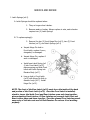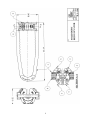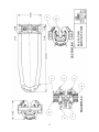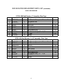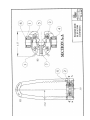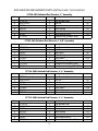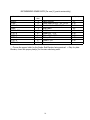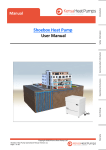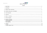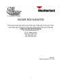
1
“a commitment to quality”
SUCKER ROD ELEVATOR
27725-100 27726-100 27727-100 27728-100 27729-100 27730-100 27731100 27732-100 27733-100 27734-100 27735-100 27736-100 27750-100
OPERATION AND SERVICE MANUAL
Oil Country Manufacturing, Inc.
300 W. Stanley Avenue
Ventura, CA 93001 USA
TEL: (805) 643 1200
FAX: (805) 643 6832
OSM-023
Last Revised Date: 11-03-06
1
TABLE OF CONTENTS
PAGE
INTRODUCTION
2
INSPECTION AND MAINTENANCE
3
SERVICE AND REPAIR
Latch Springs
4
Rear Latch
5
Front Latch
6
INSPECTION MEASUREMENTS
7
SOLID BODY ROD ELEVATOR ILLUSTRATION
8
PARTS LIST – SOLID BODY TYPE ELEVATOR
9
PLATE TYPE ROD ELEVATOR ILLUSTRATION
10
PARTS LIST – PLATE TYPE ROD ELEVATOR
11–12
POLISH ROD ELEVATOR ILLUSTRATION
13
PARTS LIST – POLISH ROD TYPE ELEVATOR
14
RECOMMENDED SPARE PARTS
15
2
INTRODUCTION
Oil Country Sucker Rod Elevators have been carefully engineered and manufactured to
provide maximum rod string protection, ease of handling and operation, and wear
resistance. The seat for the rod upset radius is machined to produce a precision fit, thus
preventing both tilting of the elevator body and local stressing or kinking of the rods.
The one-piece body is made of alloy steel, heat-treated for extra strength and wear
resistance; the forged bail is stiffened at the bend with an “I” section to prevent bending
under maximum loads. Two pairs of pressure-sensitive latches automatically close on the
rod, securely locking it in place. The rod can be released quickly and easily, by thumb
and finger pressure alone, at either the front or rear of the body. Oil Country deep-well
elevators have the reserve strength to handle the deepest wells being pumped with
sucker rods today. The rod elevators are rated at 25 tons.
3
INSPECTION AND MAINTENANCE
DAILY:
1. Clean the elevator, removing all dirt and grease.
2. Check to insure both the Front and Rear Latches close after being opened.
Do not use if they do not.
3. Check the Front Latches for wear on the Rod Gate. Gap between the two (2)
Gates should not be greater than 3/8”, replace if necessary.
4. Oil latches so they operate easily and properly.
WEEKLY:
1. Perform Daily maintenance as instructed.
2. Inspect the following areas for excessive wear and/or damage. Do not use if
excessive wear and/or damage are present. Repair or Replace the rod elevators.
Refer to inspection measurements on page
Bail, where the Sucker Rod Hook rides.
Bail PinHoles and Body Pins.
Sucker Rod Pockets (Solid body) or Plates.
SEMI-ANNUALLY AND ANNUALLY:
1. Perform Daily maintenance as instructed.
2. Perform Weekly maintenance as instructed.
3. Have all load-bearing components NDE examined for cracks. The load bearing
components are the Bail, Body, and Plates (only on plate type). If cracks are
present, replace damaged component or contact factory.
4. Load test the final assembly to 1 times maximum working load (50,000 lbs.) for
five minutes. Test should be documented and kept on file.
NOTE: The Oil Country Sucker Rod Elevator is a load-bearing item
manufactured from Alloy Steel and heat-treated. No repairs and/or remanufacturing should be done if welding is performed without consulting
factory. Unauthorized and/or undocumented welding on this tong is not
recommended and will void warranty and load rating.
4
SERVICE AND REPAIR
I. Latch Springs (ref 4)
A. Latch Springs should be replaced when:
1. They no longer close Latches.
2. Become weak or broken. Always replace in sets, each elevator
requires two (2) Latch Springs.
B. To replace spring(s):
3. Remove the two (2) front Hinge Pins (ref 2), two (2) Front
Latches (ref 5), and Latch Springs (ref 4)
a. Inspect Hinge Pin hole in
Front Latch, replace if worn,
elongated, or damaged.
b. Inspect Hinge Pin, replace if
worn or damaged.
c. Install new Latch Spring (ref
4) into Front Latch (ref 5),
depress spring and slide Front
Latch with Latch Spring into
Elevator Body (ref 7).
d. Line up hole in Front Latch
(ref 5) with Hinge Pin Hole in
elevator body (ref 7). Install
Hinge Pin (ref 2).
NOTE: The front of the Rear Latch (ref 3) must be on the inside of the back
end portion of the Front Latch (ref 5). Once the Front Latch is installed,
check to insure that both Front and Rear Latches open and close together
when actuating Front Latches. If Rear Latches are pressed, both Front and
Rear Latches open and close together. Then the opened Front Latches permit
easy entry of rod into seat area of Rod Elevator. Do not use if not working
properly.
5
SERVICE AND REPAIR
(CONTINUED)
II. Rear Latch (ref 2)
A. Replace if:
1. Hinge Pin hole is worn.
2. Front Latches no longer opens when Rear Latches are depressed.
3. Rear Latch appears damaged.
B. To replace Rear Latches
1. After removing the two (2) rear Hinge Pins (Ref 2), remove
the Rear Latches (ref 3).
a.
Inspect Rear Hinge Pins (ref 2)
and replace if worn or
damaged.
b.
Inspect area where Rear Latch
contacts Front Latch, replace
Front Latch (ref 5) if worn
excessively.
c.
Install new Rear Latch (ref 3)
into Elevator Body (ref 7).
d.
Line up hole in Rear Latch with
the Hinge Pin hole of Elevator
Body. Install Hinge Pin (ref 2).
NOTE: The front of the Rear Latch (ref 3) must be on the inside of the back
end portion of the Front Latch (ref 5). Once the Rear Latches are installed,
check to insure that both Front and Rear Latches open and close together
when actuating Front Latches. If Rear Latches are pressed, both Front and
Rear Latches open and close together. Then the opened Front Latches permit
easy entry of rod into seat area of Rod Elevator. Do not use if not working
properly.
6
SERVICE AND REPAIR
(CONTINUED)
III. Front Latch (ref 5)
A. Replace if:
1. Rod Gate of Front Latches are worn. Gap between gate sides
should not be greater than 3/8” apart.
2. Hinge Pin Hole is worn and/or elongated.
3. Latch appears damaged.
B. To replace Front Latches
1. Remove the two (2) front Hinge Pins (ref 2), two (2)
front Latches (ref 5) and Latch Springs (ref 4).
a.
Inspect Hinge Pin, replace if
worn or damaged.
b.
Install new Latch Spring (ref
4) into Front Latch (ref 5),
depress spring and slide
c.
Front Latch with Latch
Spring into Elevator Body
(ref 7).
d.
Line up hole in Front Latch
(ref 5) with Hinge Pin Hole
in elevator body (ref 7).
e.
Install Hinge Pin (ref 2).
NOTE: The front of the Rear Latch (ref 3) must be on the inside of the back
end portion of the Front Latch (ref 5). Once the Rear Latches are installed,
check to insure that both Front and Rear Latches open and close together
when actuating Front Latches. If Rear Latches are pressed, both Front and
Rear Latches open and close together. Then the opened Front Latches
permit easy entry of rod into seat area of Rod Elevator. Do not use if not
working properly.
7
INSPECTION MEASUREMENTS
I.
Hinge Pins
A. New Size: .500+ .012/-0
B. Replace if wear pattern shows in center section.
II.
Hinge Pin Holes (Elevator Body)
A. New Size: .500+0/-.003
B. Consult factory or replace if elongated or greater than .512.
III. Front/Rear Latch
A. Hinge Pin Hole new: .520
B. Replace if elongated or over .535.
C. Replace if damaged, bent, or worn in contact.
IV.
Bail Bend (where Sucker Rod Hook contacts)
A. New size: 1.450”.
B. Consult factory, re-rate elevator capacity, or replace if worn 1/16” or
greater.
V.
Bail Pins (Elevator Body/Bail Holes, Bail)
A. Bail Pins new: 1.450”, Bail Holes New: 1.500”.
B. Consult factory or replace if Bail, while being worked, moves up/down
greater than .125 (1/8”).
VI.
Elevator Body
A. Replace or consult factory if:
1. Hinge Pin holes are worn.
2. Sucker Rod pockets are worn.
3. Bail Pins are worn and/or elongated.
4. Body shows cracks or damage.
8
9
ROD ELEVATOR REPLACEMENT PARTS LIST
SOLID BODY TYPE ELEVATORS
27725-100 Rod Elevator 5/8” – ¾” Assembly
REF NO.
PART NUMBER
NO. REQ
DESCRIPTION
1
2
3
4
5
6
7
27750-01
992011-214
12639
992315
11746
28148
27725-01
1
4
2
2
2
4
1
Rod Elevator Bail
Roll Pin
Rear Latch
Latch Spring
3/4” - 7/8” Front Latch
Split Retainer Ring
Rod Elevator Body
WGT(lbs)
.09
.40
.13
1.10
.19
27726-100 Rod Elevator ¾” – 7/8” Assembly
REF NO.
PART NUMBER
NO. REQ
DESCRIPTION
1
2
3
4
5
6
7
27750-01
992011-214
12639
992315
11746
28148
27726-01
1
4
2
2
2
4
1
Rod Elevator Bail
Roll Pin
Rear Latch
Latch Spring
3/4” - 7/8” Front Latch
Split Retainer Ring
Rod Elevator Body, 3/4” - 7/8”
WGT(lbs)
.09
.40
.13
1.10
.19
27727-100 Rod Elevator 1” Assembly
REF NO.
PART NUMBER
NO. REQ
DESCRIPTION
1
2
3
4
5
6
7
27750-01
992011-214
12639
992315
11746-1
28148
27727-01
1
4
2
2
2
4
1
Rod Elevator Bail
Roll Pin
Rear Latch
Latch Spring
1” - 1-1/8” Front Latch
Split Retainer Ring
Rod Elevator Body, 1”
WGT(lbs)
.09
.40
.13
1.10
.19
27750-100 Rod Elevator 1 1/8” Assembly
REF NO.
PART NUMBER
NO. REQ
DESCRIPTION
1
2
3
4
5
6
7
27750-01
992011-214
12639
992315
11746-1
28148
27751-01
1
4
2
2
2
4
1
Rod Elevator Bail
Roll Pin
Rear Latch
Latch Spring
1” - 1-1/8” Front Latch
Split Retainer Ring
Rod Elevator Body, 1-1/8”
10
WGT(lbs)
.09
.40
.13
1.10
.19
11
ROD ELEVATOR REPLACEMENT PARTS LIST (CONTINUED)
PLATE TYPE ELEVATORS
27728-100 Rod Elevator, 1/2” Assembly, Plate Type
REF NO.
PART NUMBER
NO. REQ
1
2
3
4
5
6
7
8
9
27740-150
27750-01
992011-214
12639
992315
11746
28148
27727-62
27727-D
27727-40
1
1
4
2
2
2
4
1
2
4
DESCRIPTION
Rod Elevator Subassy less Plate and Screws
Rod Elevator Bail
Roll Pin
Rear Latch
Latch Spring
Front Latch
Split Retainer Ring
Rod Elevator Body, 1/2” - 1-1/8”
1/2” Plate
Screws
WGT(lbs)
.09
.40
.13
1.10
.19
1.50
27729-100 Rod Elevator 5/8” – ¾” Assembly, Plate Type
REF NO.
PART NUMBER
NO. REQ
1
2
3
4
5
6
7
8
9
27740-150
27750-01
992011-214
12639
992315
11746
28148
27727-62
27727-A
27727-40
1
1
4
2
2
2
4
1
2
4
DESCRIPTION
Rod Elevator Subassy less Plate and Screws
Rod Elevator Bail
Roll Pin
Rear Latch
Latch Spring
Front Latch
Split Retainer Ring
Rod Elevator Body, 1/2” - 1-1/8”
5/8” - 3/4” Plate
Screws
WGT(lbs)
.09
.40
.13
1.10
.19
1.50
27730-100 Rod Elevator ¾” – 7/8” Assembly, Plate Type
REF NO.
PART NUMBER
NO. REQ
1
2
3
4
5
6
7
8
9
27740-150
27750-01
992011-214
12639
992315
11746
28148
27727-62
27727-B
27727-40
1
1
4
2
2
2
4
1
2
4
DESCRIPTION
Rod Elevator Subassy less Plate and Screws
Rod Elevator Bail
Roll Pin
Rear Latch
Latch Spring
Front Latch
Split Retainer Ring
Rod Elevator Body, 1/2” - 1-1/8”
3/4” - 7/8” Plate
Screws
12
WGT(lbs)
.09
.40
.13
1.10
.19
1.50
ROD ELEVATOR REPLACEMENT PARTS LIST
(CONTINUED)
PLATE TYPE ELEVATORS
27731-100 Rod Elevator, 1” Assembly, Plate Type
REF NO.
PART NUMBER
NO. REQ
1
2
3
4
5
6
7
8
9
27740-150
27750-01
992011-214
12639
992315
11746
28148
27727-62
27727-C
27727-40
1
1
4
2
2
2
4
1
2
4
DESCRIPTION
Rod Elevator Subassy less Plate and Screws
Rod Elevator Bail
Roll Pin
Rear Latch
Latch Spring
Front Latch
Split Retainer Ring
Rod Elevator Body, 1/2” - 1-1/8”
1” Plate
Screws
WGT(lbs)
.09
.40
.13
1.10
.19
1.50
27732-100 Rod Elevator 1 1/8” Assembly, Plate Type
REF NO.
PART NUMBER
NO. REQ
1
2
3
4
5
6
7
8
9
27740-150
27750-01
992011-214
12639
992315
11746
28148
27727-62
27727-E
27727-40
1
1
4
2
2
2
4
1
2
4
DESCRIPTION
Rod Elevator Subassy less Plate and Screws
Rod Elevator Bail
Roll Pin
Rear Latch
Latch Spring
Front Latch
Split Retainer Ring
Rod Elevator Body, 1/2” - 1-1/8”
1-1/8” Plate
Screws
13
WGT(lbs)
.09
.40
.13
1.10
.19
1.50
14
ROD ELEVATOR REPLACEMENT PARTS LISTSOLID BODY TYPE ELEVATORS
27736-100 Polished Rod Elevator, 1” Assembly
REF NO.
PART NUMBER
NO. REQ
1
2
3
4
5
6
7
27750-01
992011-214
12639
992315
11746-5
28148
27732-01
1
4
2
2
2
4
1
DESCRIPTION
Rod Elevator Bail
Roll Pin
Rear Latch
Latch Spring
Front Latch
Split Retainer Ring
Polished Rod Elevator Body
WGT(lbs)
.09
.40
.13
1.10
.19
27733-100 Polished Rod Elevator, 1 1/8” Assembly
REF NO.
PART NUMBER
NO. REQ
1
2
3
4
5
6
7
7
27750-01
992011-214
12639
992315
11746-5
28148
27733-01
27726-01
1
4
2
2
2
4
1
1
DESCRIPTION
Rod Elevator Bail
Roll Pin
Rear Latch
Latch Spring
Front Latch
Split Retainer Ring
Polished Rod Elevator Body
Rod Elevator Body, 3/4” - 7/8”
WGT(lbs)
.09
.40
.13
1.10
.19
27734-100 Polished Rod Elevator, 1 ¼” Assembly
REF NO.
PART NUMBER
NO. REQ
1
2
3
4
5
6
7
27750-01
992011-214
12639
992315
11746-6
28148
27734-01
1
4
2
2
2
4
1
DESCRIPTION
Rod Elevator Bail
Roll Pin
Rear Latch
Latch Spring
Front Latch
Split Retainer Ring
Polished Rod Elevator Body
WGT(lbs)
.09
.40
.13
1.10
.19
27735-100 Polished Rod Elevator, 1 ½” Assembly
REF NO.
PART NUMBER
NO. REQ
1
2
3
4
5
6
7
27750-01
992011-214
12639
992315
11746-7
28148
27735-01
1
4
2
2
2
4
1
15
DESCRIPTION
Rod Elevator Bail
Roll Pin
Rear Latch
Latch Spring
Front Latch
Split Retainer Ring
Polished Rod Elevator Body
WGT(lbs)
.09
.40
.13
1.10
.19
RECOMMENDED SPARE PARTS (For one (1) year’s service duty)
PART NUMBER
NO.
RECC.
DESCRIPTION
WGT(LBS)
992315
11746
11746-1
12639
992011-214
27727-A
27727-B
27727-C
27727-E
27727-40
4
2*
2*
2
8
4**
4**
4**
4**
12**
Latch Springs
Front Latch for 5/8”, 3/4” & 7/8”
Front Latch for 1” & 1 1/8”
Rear Latch
Roll Pins
Plates 5/8” - 3/4”
Plates 3/4” - 7/8”
Plates, 1”
Plates 1-1/8”
Screws
.13
1.10
1.10
.40
.09
1.50
1.50
1.50
1.50
Choose the proper Latch for the Sucker Rod Elevator being serviced.
Elevator, chose the proper plate(s) for the size rods being used.
*
16
**
Only for plate