1
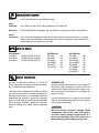
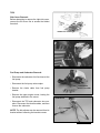
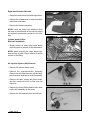
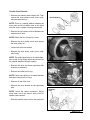
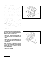
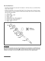
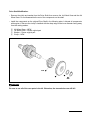
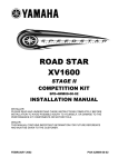
MOTORCYCLE
1/9/2004
M2004-001
© 2004 YAMAHA MOTOR CORPORATION, U.S.A.
RECALL
This modification has top priority. This bulletin must be
performed immediately to ensure customer safety.
2001~2003 XV16 MODELS
FACTORY MODIFICATION CAMPAIGN
Yamaha Motor Corporation, U.S.A., has determined that a defect which relates to motor vehicle safety
exists in certain 2001 XV16 (“Road Star,” “Midnight Star,” and “Road Star Silverado”) model motorcycles, and in 2002 and 2003 XV16 (“Road Star,” “Road Star Limited Edition,” “Midnight Star,” and “Road
Star Silverado”) motorcycles. In affected motorcycles, certain transmission components may not meet
Yamaha quality-control standards, which could allow abnormal wear that eventually results in a broken
retaining circlip. If the circlip breaks, the transmission could lock up, which would also cause the rear
wheel to lock up. This could result in loss of control and a vehicle crash with injury or death.
To correct this defect, Yamaha is initiating a Factory Modification Campaign. Affected motorcycles must
have certain transmission components replaced with new ones.
Yamaha is notifying all registered owners of affected motorcycles by mail. A copy of this letter is included in this bulletin. The customer should take the letter along with the affected motorcycle to an authorized Yamaha dealer for the modification.
A computer report listing all affected motorcycles invoiced to your dealership is included with this bulletin. Use the list to help ensure all motorcycles are modified. All sold motorcycles that have been registered with Yamaha will show the customer’s name and address. Your dealership must notify the owner
of any affected motorcycle that was actually sold but is listed as “unsold” in the report.
You must modify all affected motorcycles in your inventory as well as all customer-owned motorcycles
brought to you for this service. Any affected motorcycle that you purchase from Yamaha in the future will
also require modification. If you purchase a motorcycle from another dealer, check to see if the procedures in this bulletin have already been performed before you sell the motorcycle.
Motorcycles that are affected should not be operated until they are modified. It is a violation of
Yamaha policy for your dealership to deliver any affected motorcycles to customers until the
procedures in this bulletin are performed.
When the modification on each motorcycle is performed, follow the Warranty Information section of this
bulletin to receive reimbursement. Be sure to use the Factory Modification Campaign procedures in
Chapter 8 of the Warranty and Y.E.S. Handbook (LIT-11760-00-03).
PAGE 1 of 12
Modify:
All XV16 motorcycles in the affected range.
Parts
Required:
Yes. Order one 4th Pinion Gear Exchange Kit for each unit.
Warranty:
Factory Modification Campaign. See the Warranty Information section of this bulletin.
Notify
Customers: Yes. You must immediately contact any customer whose motorcycle shows as unregistered on the enclosed report. Yamaha has sent letters to customers whose motorcycles
were registered for warranty as of 1/8/04
2001 Models
XV16AN
VP02E-015196~016113
XV16ASN
VP02E-014871~016033
XV16ATN
VP07E-006069~007073
2002 Models
XV16AP
XV16APC
XV16ASP
XV16ASPC
XV16ATP
XV16ATPC
Use the XV1600 service manual (LIT-11616-1256) for information on engine removal, disassembly, re-assembly, and installation.
The information contained in this section will give
you tips or short cuts on certain procedures to
help you work efficiently. For example, when disassembling the engine to access the transmission, it is not necessary to remove the camshafts,
lifters, or stator assembly. Review the tips and
become familiar with them before beginning
work.
All
All
All
All
All
All
2003 Models
XV16AR
XV16ARC
XV16ALER
XV16ALERC
XV16ASR
XV16ASRC
XV16ATR
XV16ATRC
All
All
All
All
All
All
All
All
PREPARATION
Properly secure the motorcycle on a suitable lift.
Drain the oil from the engine, reservoir tank, and
transfer case. Remove the fuel tank, exhaust system, fuel system, drive system, etc. to prepare for
engine removal.
Lay the components out in order of removal and
keep all the fasteners separated for each component to ease re-assembly.
CAUTION:
Avoid accidental cosmetic damage. Place
components such as fuel tank, side covers,
and other easily damaged components in a
secure and protected area. Take special care
when removing and installing accessories.
PAGE 2 of 12
TIPS
Side Cover Removal:
Before attempting to remove the right side cover,
remove the left cover first to access the hidden
6mm bolt.
HIDDEN 6mm SCREW
6mm BOLT
Fuel Pump and Carburetor Removal:
• Disconnect the carburetor fuel line hose at the
fuel pump.
• Disconnect the fuel pump wire coupler.
UPPER ENGINE
MOUNT/ FUEL PUMP
• Remove the choke cable from fuel pump
bracket.
• Remove the upper engine mount, leaving the
fuel pump attached to the mount.
CARBURETOR
• Disconnect the TPS and carburetor wire couplers. Disconnect the throttle cables, and then
remove the carburetor.
NOTE: The idle adjuster can be removed from its
bracket without loosening the bracket screws.
PAGE 3 of 12
Right-Hand Footrest Removal:
• Disconnect and remove the brake light switch.
• Remove the forward-most tie wrap around the
brake hose and frame.
FOOTREST
ASSEMBLY
• Remove the footrest assembly.
NOTE: Leave the brake hose attached. Move
the hose to the underside of the foot rest mount
and support it as necessary so that it is out of the
way
Cylinder Head Oil Pipe
Removal/ Installation:
• Slightly loosen all three banjo bolts before
removing them to prevent oil line deformation.
UPPER
BANJO
BOLT
NOTE: When loosening the upper banjo bolts,
hold the line in place using a wrench at the flat
surface on the fitting.
Air Injection System (AIS) Removal:
AIS AIR FILTER
• Remove the electric starter motor.
• Remove the regulator/rectifier assembly.
Remove the AIS pipes from the cylinder head,
but leave them attached to the AIS assembly.
• Remove the three screws with 8mm heads,
and then remove the AIS air filter from the
right side.
• Remove the three Phillips head screws holding the AIS assembly on the frame.
• Remove the AIS assembly from the left side.
PAGE 4 of 12
AIS ASSEMBLY
Transfer Case Removal:
• Remove the transfer case bracket first. Then
remove the outer chrome cover, inner cover,
and drive-sprocket nut.
SEALING WASHER
NOTE: There is a sealing washer between the
inner case and the transfer case at the 8mm
stud. Be sure to replace it during re-assembly.
• Remove the two chrome oil lines between the
engine and oil tank.
NOTE: Retain the four O-rings for re-use.
BEVEL ON
OUTSIDE DIAMETER
• Remove the drive pulley cover and remove
the drive pulley nut.
• Loosen the drive belt tension.
• Remove the drive pulley, inner cover, collar,
and O-ring.
NOTE: The collar has a bevel on its inside diameter for the O-ring facing inward and a bevel on
the outside diameter facing the pulley.
• Remove the drive and driven sprockets with
chain as an assembly.
• Remove the collar and O-ring.
NOTE: Collar has a bevel on its inside diameter
that faces inward for the O-ring.
RELAY BRACKET
• Remove oil tank filler neck.
• Remove the relay bracket on the right-hand
side.
NOTE: Leave the relays connected. Simply
move them out of the way to allow room for
transfer case removal.
TRANSFER
CASE
• Slide the transfer case out from the right side.
PAGE 5 of 12
Engine Removal/Installation:
• When the engine is ready to be removed from
the frame, be sure to disconnect all wire connectors and remove the oil filter bracket.
• Remove all engine mounting bolts and brackets.
• Protect all right side frame tubes with protective tape or an equivalent to prevent scratches.
STEEL RODS
• Insert steel rods in front and rear engine
mount holes and with one person on each
side of the engine lift the engine up and out to
the right.
NOTE: Use 7/16" (10mm) steel rod at least 20"
long. The steel rods used to compress the rear
suspension of ATVs in their shipping crate work
well.
Engine Tear Down:
Place the engine on a work bench or work surface covered with cardboard or other protective
material to protect the engine finish.
• Remove the left-hand generator shaft end
cover and remove the generator shaft bolt and
washer.
• Remove the clutch, primary drive gear, shift
shaft, shift detent, oil pump gear and oil
crossover pipe.
NOTE: The right side of the crossover pipe has
an O-ring. If the O-ring doesn't come out with the
crossover pipe, be sure to remove it while the
engine is disassembled.
• Remove both top ends
PAGE 6 of 12
GENERATOR
SHAFT END COVER
NOTE: Do not remove the push rod tubes from
the crankcase. Remove only one circlip from the
piston for quicker piston pin removal.
1
3
6
2
• Remove the right side crankcase bolts (three
8mm and three 6mm) only.
NOTE: Do not remove the cam cover or generator cover.
• Tilt the engine to the right and rest the cam
cover against a block covered with cardboard
or other protective material to protect the
engine finish. Remove the left-side crankcase
bolts (6mm bolts, quantity 15).
5
4
21
7
20
19
9
• Align the shift cam segment with the segmentshaped hole in the crankcase.
• While holding the crankshaft against the right
crankcase, remove the left crankcase half.
10
18
17
11
8
16
12
15
14
13
CAUTION:
Be sure to hold the crankshaft against the
right case half to prevent disengagement of
the camshaft drive gear.
• Remove the shift fork shafts, shift forks, and
transmission.
PAGE 7 of 12
Main Shaft Modification:
• Completely disassemble the main shaft. The Washer 7, 5th Pinion Gear 6, and 2nd/3rd Pinion
Gear 5 will be reused.
• Install the components on the new-type Main Shaft 9 in the following order. Lubricate all components with engine oil. Be sure circlips are installed with the sharp edge of the inner diameter facing
away from the mating washer.
1
2
3
4
5
6
7
8
Collar – NEW
4th Pinion Gear – NEW
Washer – NEW
Circlip – NEW
2nd/3rd Pinion Gear – Reuse original part
5th Pinion Gear – Reuse original part
Washer – Reuse original part
Circlip – NEW
NEW 8
7
DO NOT
USE ORIGINAL
3-TANG WASHER
6
5
NEW 4
NEW 3
NEW 2
NEW 1
NEW 9
WARNING
Be sure to use all of the new parts in the kit. Otherwise, the transmission can still fail. Be sure
that you are installing the new washer 3. It is thicker than the original and can be easily identified by its six tangs on the inner diameter instead of the three on the original washer.
PAGE 8 of 12
Drive Shaft Modification:
• Remove the circlip and washer from the Drive Shaft, then remove the 1st Wheel Gear and the 4th
Wheel Gear. Do not disassemble the rest of the components on the shaft.
• Install the components on the original Drive Shaft in the following order. Lubricate all components
with engine oil. Be sure the circlip is installed with the sharp edge of the inner diameter facing away
from the mating washer.
1
2
3
4
4th Wheel Gear – NEW
1st Wheel Gear – Reuse original part
Washer – Reuse original part
Circlip – NEW
NEW 1
2
3
4
NEW
WARNING
Be sure to use all of the new parts in the kit. Otherwise, the transmission can still fail.
PAGE 9 of 12
Part Number
90891-10117-00
Description
4th Pinion Gear Exchange Kit
• Axle, Main (4WM-17411-A0-00)
• Gear, 4th Pinion (5VN-17141-00-00)
• Collar (90387-281T8-00)
• Washer (90209-25013-00)
• Circlip (93410-23056-00)
• Circlip (93440-28062-00)
• Gear, 4th Wheel (4NK-17241-02-00)
• Circlip (93410-25017-00)
• Circlip (93450-24028-00)
• Piston Ring Set (34L-11610-00-00)
• Washer, Lock (90215-25218-00)
• Gasket, Crankcase Cover1 (5PX-15451-00-00)
• Gasket, Cyl. Head 2 (4WM-11182-00-00)
• Gasket, Head Cover 1 (4WM-11193-00-00)
• Gasket, Head Cover 2( 4WM-11194-00-00)
• Gasket, Cyl. (4WM-11351-00-00)
• Gasket, Cyl. Head 1 (4WM-11181-00-00)
• Gasket, Exhaust Pipe (3EG-14613-00-00)
• Gasket, Silencer (3XW-14755-00-00)
• Intake Manifold O-Ring (93210-505A4-00)
• Gasket 1 (5PX-17929-00-00)
• Washer, Lock (90215-26241-00)
• Element Assy, Oil Cleaner (3FV-13440-10-00)
• O-ring (93210-06667-00)
• Gasket 2 (4WM-17931-00-00)
• Washer, Plate (90201-08087-00)
• Gasket (90430-10171-00)
Qty
1
•1
•1
•1
•1
•1
•1
•1
•1
•2
•2
•1
•1
•2
•2
•2
•2
•2
•2
•2
•2
•1
•2
•1
•1
•1
•2
•4
Dealer
Cost
$79.49
After modifying a unit, make a punch mark
above the frame number (VIN) on the steering
head pipe as shown in the illustration below.
PUNCH MARK HERE
*
JYAVP02Y81A001XXX
PAGE 10 of 12
The owner of each warranty-registered affected unit will receive a letter announcing this campaign.
The letter has a label that includes the Primary ID and Recall Number. Use this information when submitting for reimbursement as described below.
The modification is authorized for all affected motorcycles, both sold and unsold, regardless of ownership or warranty status. You do not need the customer’s letter to perform the modification or to file
for reimbursement.
Submit a Recall Request for the transmission replacement as described below using Recall Number
990021. Choose the status “M.” You will be reimbursed a labor allowance of 9.0 hours, which includes
a reimbursement amount for oil and other shop supplies, plus the cost of the 4th Pinion Gear
Exchange Kit and your handling fee.
YDS:
When signed on to YDS, click on the Service Tab, and then “Recall Request-Add.” This function has
recently been improved to allow you to enter multiple Primary IDs for the same recall. Remember that
YDS now requires a 7-digit serial number, so use a “0” as the first digit. The system will check your
submission instantly to make sure the Primary ID numbers you’ve entered are valid for the recall. You
can check back the next day for your claim numbers to track your credit.
MAIL:
Complete a recall Reimbursement Request (LIT-11790-00-97) as shown below:
9 9 0 0 2 1
V P 0 2 E
0 1 4 XX X
0 1 - 1 5 - 2 0 0 4
If you have any questions about proper procedures for Factory Modification Campaigns, see Chapter
8 in your Warranty and Y.E.S. Handbook (LIT-11760-00-03).
PAGE 11 of 12
6555 Katella Avenue, Cypress, California 90630-5101 (714) 761-7300
SAFETY RECALL NOTICE
January 9, 2004
Dear Yamaha Owner:
This notice is sent to you in accordance with the requirements of the National Traffic and Motor Vehicle Safety Act. Yamaha Motor
Corporation, U.S.A., has decided that a defect which relates to motor vehicle safety exists in certain 2001 XV16 (“Road Star,” “Midnight
Star,” and “Road Star Silverado”) model motorcycles, and in 2002 and 2003 XV16 (“Road Star,” “Road Star Limited Edition,” “Midnight
Star,” and “Road Star Silverado”) motorcycles. Our records show that you own the affected motorcycle shown on the label above.
The reason for this
recall:
In affected motorcycles, certain transmission components may not meet Yamaha quality-control standards, which could allow abnormal wear that eventually results in a broken retaining circlip. If the circlip
breaks, the transmission could lock up, which would also cause the rear wheel to lock up. This could result
in loss of control and a vehicle crash with injury or death.
What Yamaha and
your dealer will do:
To correct this defect, your authorized Yamaha dealer will replace certain transmission components with
new ones. There will be no charge to you for this procedure. Your dealer will probably need to keep
your motorcycle for at least two days to accomplish the required modification
What you should do
now:
Please call your Yamaha dealer to make a service appointment to have this procedure performed. At that
same time you can find out how long he expects he will need to keep your motorcycle for this service.
Remember to take this letter with you when you take in your Road Star or Midnight Star motorcycle.
You should not ride your motorcycle until this modification is performed. If your motorcycle’s transmission needed a repair previously, you should still have this modification performed now. If those
previous transmission repairs were made at your expense, you should ask the servicing Yamaha dealer
to contact Yamaha Customer Relations if the failure involved a broken circlip.
If you are unable to return to the Yamaha dealer who sold you the motorcycle, this service will be performed by any authorized Yamaha Motorcycle dealer. For the name of a dealer near you, call 1-800-88YAMAHA or visit the Yamaha web site at: www.yamaha-motor.com.
If you need help:
If, after contacting your dealership, you have questions or concerns which the dealership is unable to
answer, please write to
Yamaha Motor Corporation, USA
Customer Relations Department
P.O. Box 6555
Cypress CA 90630
If, after contacting Yamaha Customer Relations, you are still not satisfied that we have done our best to
remedy the situation without charge and within a reasonable time, you may submit a written complaint to
the Administrator, National Highway Traffic Safety Administration, 400 Seventh St. SW, Washington, DC
20590 or call the Auto Safety Hotline at 888-327-4236.
If you no longer own
this Yamaha:
If you have sold your motorcycle to another party, please call us toll-free at 1-800-227-5963 with the name
and address of the new owner, along with the serial number shown above your name on the address label
above.
We’re sorry to cause you any inconvenience, but we are sincerely concerned about your safety and continued satisfaction with our
products. Thank you for giving your attention to this important matter.
Sincerely,
Customer Support Group
Yamaha Motor Corporation, USA
PAGE 12 of 12