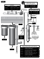
1
Installation, Operation and Maintenance
Owner’s Manual
SC200-DWS11, SCm200-DWS11
SC320-dws12, SC320-dws22,
SCm320-dws12, SCm320-dws22
Manufactured in Canada by:
425 Clair Road West P.O. Box 1719
Guelph, ON N1L 1R1 Canada
t. 519.763.1032 • f. 519.763.5069
e. [email protected] • i. www.r-can.com
EPA# 57987-CN-001
June 2008
P/N 520114
Why buy original factory specified lamps...
• All Sterilight® systems are third-party verified in actual biodosimetry tests (complete
bacteriological evaluation of the system, not just electrical output of the lamp).
• All Sterilight® UV systems are CSA certified with Sterilume® lamps. The use of any
replacement lamp other than the original Sterilume® replacement will result in voiding
the CSA certification and placing the onus of electrical safety in the hands of the user
(this will also affect possible insurance coverage if required).
• R-Can WILL NOT warranty ANY component of the UV system unless genuine
Sterilume® replacement lamps are used in the system. The use of any lamp, unless
specifically authorized by the company, will result in a full voidance of the warranty NO EXCEPTIONS.
• Regardless of what another lamp vendor may tell you, R-Can can not guarantee the
efficacy of the UV system without the use of genuine Sterilume® UV lamps.
Why are Sterilume® lamps the best available...
• NEW Environmentally Friendly lamps throughout our entire product offering; Low
mercury (Hg) technology provides lamps with less than 10 mg of mercury including our
amalgam lamps (up to 70% less mercury than the competition).
• All Sterilume® lamps are TCLP* compliant and meet current US state requirements
regarding the “Mercury Phase-Out” program.
• Proprietary LongLife+™ coating eliminates the common problem of accelerated
depreciation so often associated with higher intensity lamps ... provides stability, longer
life and increased efficiency.
• All lamps are manufactured in hard glass (quartz) with durable ceramic end cap
construction and date and colour coded for easy identification.
• Full one-year warranty on all Sterilume® UV lamps.
• Flexibility of vertical installation on amalgam lamps.
* Note: The United States Environmental Protection Agency’s (EPA) Toxicity Characteristic Leaching Procedure (TCLP) is used by the Federal
Government and most states to determine whether or not spent
fluorescent lamps should be characterized as hazardous waste.
Recycle...
• R-Can encourages the recycling of all spent UV lamps at the end of lamp life. Please refer
to www.lamprecycle.org for information on recycling regulations in your area.
Congratulations, you have just
purchased the Sterilight® Cobalt™
drinking water system. By purchasing
this device, you have taken the first step
in ensuring the safety of your water
supply by using a totally non-intrusive,
physical disinfection method. Your
Sterilight system uses the most
advanced UV technology on the market
and is designed to provide you with
years of trouble free operation with
minimal maintenance required.
Table of Contents:
Parts / Schematic Breakdown
1
Safety Instructions
2
Water Chemistry
3
Installing Your UV Disinfection System
3-5
Disinfection Procedure
6-7
Operating and Maintenance Instructions
7-10
Operation
11-14
Troubleshooting
15-16
Dose Flow Chart
16
Specifications
17-18
Manufacture’s Warranty
19
*CSA/UL certification with approved power cord and lamps only.
Symbols:
Caution
Protective
Ground
Electrical
Warning
Fragile
Eye Protection
WEEE (waste
electrical or
electronic
equipment)*
* This symbol indicates that you should not discard wasted electrical or electronic
equipment (WEEE) in the trash. For proper disposal, contact your local recycling/reuse
or hazardous waste center.
Parts:
Hard glass, coated Sterilume®ho UV lamps for long,
consistent life (9000 hours)
Controller
s200rl-ho
For 200 series
power - 100-240V/50-60Hz
s320rl-ho
For 320 series
ba-ice-c
Cobalt “BASIC” system
ba-ice-cm
cobalt “PLUS” system
lamp connector
retaining clip
214 fused quartz sleeves
with fire polished ends
qs-200
For 200 series
qs-320
For 320 series
aluminum
gland nut
RN-001
o-ring
or-212
bracket
420483
optional
flow
restrictor
UV sensor
254NM-C1
“PLUS”
systems
only
filter
fb1-1pr
optional
temperature
management
valve (440179)
304 stainless steel
reactors with 600
grit polish (A249
pressure rated
tube)
IEC replacement power cords for
Cobalt™ ICE Controller (sold separately)
filter
fb2-1pr
drain
plug
260010
north american (nema 5-15p),
3-prong grounded
260011
continental european (cee 7/7)
2-pin with ground, “schuko”
260012
uk version (bs 1363)
3-prong grounded (5 amp fuse)
260013
australian version (as 3112)
3-prong grounded
260019
no connector, 3-wire, bare leads
1
Safety Instructions:
WARNING - to guard against injury, basic safety precautions should be
observed, including the following:
1. READ AND FOLLOW ALL SAFETY INSTRUCTIONS.
2. CAUTION - Always disconnect power before servicing.
3. DANGER - To avoid possible electric shock, special care should be taken since water is present near electrical equipment. Unless a situation is encountered that is explicitly addressed by the provided maintenance and troubleshooting sections, do not attempt repairs yourself, refer to an authorized service facility.
4. Carefully examine the disinfection system after installation. It should not be plugged in if there is water on parts not intended to be wet such as, the ballast or lamp connector.
5. Do not operate the disinfection system if it has a damaged cord or plug,
if it is malfunctioning or if it has been dropped or damaged in any manner.
6. Always disconnect water flow and unplug the disinfection system before performing any cleaning or maintenance activities. Never yank the cord to remove from an outlet; grasp the wall plug and pull to disconnect.
7. Do not use this disinfection system for other than intended use (potable water applications). The use of attachments not recommended or sold by the manufacturer/distributor may cause an unsafe condition.
8. Intended for indoor use only. Do not install this disinfection system where it will be exposed to the weather or to temperatures below freezing. Do not store this disinfection system where it will be exposed to the weather. Do not store this disinfection system where it will be exposed to
temperatures below freezing unless all water has been drained from it and the water supply has been disconnected.
9. Read and observe all the important notices and warnings on the water disinfection system.
10. If an extension cord is necessary, a cord with a proper rating should be used. A cord rated for less Amperes or Watts than the disinfection system rating may overheat. Care should be taken to arrange the cord so that it will not be tripped over or pulled. Circuit breaker must not exceed power cord current rating (ie - 15A for North american NEMA 5-15P).
11. SAVE THESE INSTRUCTIONS.
Warning: The UV light given off by this unit can cause serious burns to
unprotected eyes and skin. Never look directly at an illuminated UV lamp.
When performing any work on the UV disinfection system always unplug the
unit first. Never operate the UV system while the UV lamp is outside of the UV
chamber.
Note: The UV lamp inside of the disinfection system is rated at an effective life of
approximately 9000 hours. To ensure continuous protection, replace the UV lamp
annually.
2
Water Chemistry:
Water quality is extremely important for the optimum performance of your UV
disinfection system. The following levels are recommended for installation:
• Iron: < 0.3 ppm (0.3 mg/L)
• Hardness*: < 7 gpg (120 mg/L)
• Turbidity: < 1 NTU
• Manganese: < 0.05 ppm (0.05 mg/L)
• Tannins: < 0.1 ppm (0.1 mg/L)
• UV Transmittance: > 75% (call factory for recommendations on applications where UVT < 75%)
* Where total hardness is less than 7 gpg, the UV unit should operate
efficiently provided the quartz sleeve is cleaned periodically. If total hardness exceeds 7 gpg, the water should be softened.
If your water chemistry contains levels in excess of those mentioned above, proper
pre-treatment is recommended to correct these water problems prior to the
installation of your UV disinfection system. These water quality parameters can be
tested by your local dealer, or by most private analytical laboratories. Proper
pre-treatment is essential for the UV disinfection system to operate as intended.
Installing your UV Disinfection System:
• CAUTION, electronic ballast must be connected to a grounded receptacle and the lamp connector ground wire connected to the stainless steel reactor chamber.
• The disinfection system is designed to be installed at point-of-entry. Drip loops in all cordage connected to ballast controller is highly recommended (see figure 1D).
• The complete water system, including any pressure or hot water tanks, must be sterilized before start up by flushing with chlorine (household bleach) to destroy any residual contamination (see page 6).
• For safety purposes, the disinfection system should be connected to a ground fault interrupt circuit.
• The disinfection system is intended for indoor use only, do not install disinfection system where it may be exposed to the weather.
• Install the disinfection system on cold water line only.
• If treating the entire house, install the disinfection system before any branch lines.
• A 5 micron sediment filter must precede the disinfection system. Ideally, the
disinfection system should be the last treatment the water receives before it reaches the faucet.
1. The picture on page 4 shows the installation of a typical drinking water system
and the related components that may be used for the installation. The use of a
by-pass assembly is recommended in case the system requires “off-line”
maintenance. If this is the case, it must be noted that the system will require supplementary disinfection of the distribution system if any water is used
during this by-pass condition. In addition, during by-pass, the water will
NOT be disinfected and the attached “DO NOT CONSUME THE WATER” tag (included with this manual), should be physically installed on the by-pass
assembly until such time as the system is sanitized and returned to service. Please refer to the complete disinfection procedure as outlined on page 6 of
this document. If the water is to be consumed while the system is off-line, the water must be boiled for twenty minutes prior to consumption.
3
optional 4-20MA “Y” cable
2. Select a suitable location for the disinfection system and its related components. As it is recommended to install a ground fault protected circuit (GFCI), make sure that this is taken into consideration prior to any installation. When selecting a mounting
location, you must leave enough space to allow for the removal of the UV lamp/quartz sleeve, as well as enough space to change out the filter cartridges (typically leave a space equal to the size of the reactor chamber itself above and below) (Figure 1A).
(Note: Installation drawings show Cobalt “PLUS” system with UV sensor for
representation purpose only)
3. Mount the system to the wall with appropriate lag bolts (not supplied) through the two
mounting holes located on the metal bracket. The use of a flow restrictor device is strongly recommended when installing your system in order to maintain the manufacturers maximum rated flow. The flow restrictor should be installed on the outlet port and is designed to be installed in one direction only. Ensure that the flow of the water matches the flow direction as indicated on the flow restrictor (Figure 1B). DO NOT SOLDER
CONNECTIONS WHILE ATTACHED TO THE
SYSTEM AS THIS COULD DAMAGE THE O-RING SEALS.
4. Make sure you allow for a “drip-loop” on the power cord and sensor (SCM series) to prevent any water from potentially entering the
controller. Run lamp and sensor cord under ballast, to prevent water from potentially entering the controller (Figure 1C). Affix the green ground wire to the grounding lug at the top of the reactor vessel and securely fasten with the lugnut provided (Figure 1D).
5. Install the UV lamp and UV sensor as outlined on pages 7-9.
6. Install the cartridges as outlined on page 10.
7. When all plumbing connections are made, slowly turn on the water supply
and check for leaks. The most likely cause for leaks is from o-ring seals. In case of a leak at the reactor, shut water off, drain cell, remove the retaining nut, wipe the o-ring and threads clean and re-install. In case of a leak at the filters, remove the sump, wipe the o-ring and threads clean, ensure the o-ring is fitted properly, then reinstall.
4
8. Once it is determined that there are no leaks, plug the system into the ground fault interrupter, and check controller to ensure the system is operating properly.
The controller is designed to detect both power to the system
and lamp illumination. It is
important to NEVER LOOK
DIRECTLY AT THE GLOWING UV LAMP.
9. Allow the water to run for a few minutes to clear any air or dust
that may be in the reactor.
PLEASE NOTE: When there is no flow,
the water in the cell will become
warm, as the UV lamp is always on.
To remedy this, run a cold water tap
anywhere in the house for a minute
to flush out the warm water.
Alternatively, install a temperature management valve (PN 440179).
5
Disinfection Procedure:
UV disinfection is a physical disinfection process and does not add any potentially
harmful chemicals to the water. As UV does not provide a disinfection residual, it
is imperative that the entire distribution system located after the UV be chemically
disinfected to ensure that the water is free from any bacteriological contaminants.
The disinfection process must be performed immediately after the UV unit is installed
and repeated thereafter whenever the UV is shut down for service, without power, or
inoperative for any reason. The procedure for sanitizing the plumbing system is
readily accomplished as follows:
1. Shut off the upstream water supply that feeds water into the reactor chamber and depressurize water system. Remove the pre-filter cartridge and fill the sump with 1-2 cups of household (5.25%) bleach (chlorine) – Do NOT use hydrogen
peroxide. Note: Make sure the carbon filter is removed from the sump while
performing this function as the carbon filter will remove the bleach from the
system thus preventing the disinfection process. At all times during this process,
make sure the UV unit (and lamp) is turned on and operational!
2. Repressurize water system, open each faucet and allow cold water to run until you smell chlorine, shut the faucet off and then repeat the process for each faucet,
including hot water. You must ensure that all taps, including outside faucets,
dishwashers, shower heads, washing machines, connections to refrigerators,
toilets, etc., pass chlorinated water.
3. Once all the locations have passed the chlorine disinfection solution, you will need to leave the solution sit for a period of 20–30 minutes. Reinstall the pre-filter cartridge into the filter and then flush the chlorine solution from the system until no chlorine smell is detectable. Make sure that each fixture that was disinfected in step two is completely flushed of the chlorine solution as the consumption of this water is not advised due to the extremely high concentrations of chlorine. It is important to remember that in the event that a UV is briefly shut down for routine cleaning or
during power interruptions where water could have passed through the system, the aforementioned procedure must also be followed.
Note A: The addition of chlorine (bleach) to a hot water tank that has in the past been fed with untreated raw water with high levels of other contaminants (iron,
manganese, hydrogen sulphide, organics, etc.) will result in oxidation of these contaminants and may require repeated flushing of the hot water tank. This contingency must be dealt with independently under the start-up procedure for any other conditioners that may form a part of the pre-treatment for the UV unit.
Note B: The above procedure (Steps 1 to 3) will result in a massive chlorine
residual far in excess of the 0.5 to 1.0 mg/L typically present in municipally
chlorinated water and of a magnitude consistent with the minimum 50 mg/L
chlorine solution recommended for the disinfection of distribution systems known to be contaminated. Do not consume water until complete system has been flushed.
PLEASE NOTE: As the SCM series systems include a 254nm UV intensity monitor, it should
be noted that the introduction of the bleach solution required for disinfection WILL trigger
a temporary low UV condition. This is due to the fact that the bleach physically “clouds”
the raw water. Once the bleach runs through the system, the alarm condition will return to
normal. During this sanitization process, the audible alarm condition on the Cobalt “Plus”
controller can be temporarily deferred by pressing the “RESET” switch for 5 seconds. By
doing this, the audible alarm will be silenced and the solenoid relay will close (AC power
will be provided to the normally closed (NC) solenoid, allowing water to pass through the
system). The system will display
on the controller LED. This condition will remain for
12 hours unless the system is manually reset as outlined on page 10 of this manual.
6
OPERATION
• Always disconnect power before performing any work on the
disinfection system.
• Regularly inspect your disinfection system to ensure that the
power indicators are on and no alarms are present.
• Replace the UV lamp annually (or biennially if seasonal home use)
to ensure maximum disinfection.
• Always drain the reactor chamber when closing a seasonal home or leaving the unit in an area subject to freezing temperatures.
Operating & Maintenance Instructions:
Caution: prior to performing any work on the disinfection system, always disconnect the power supply first. Do not use water during following procedures.
UV Lamp Replacement:
NOTE: reset lamp life timer after lamp replacement
(pG 10) – refer to www.lamprecycle.org for lamp disposal
1. To replace the lamp, there is NO need to disconnect the system from the water supply, nor to drain the water from the reactor chamber do not use water during this
procedure. Lamp replacement is a quick and simple procedure requiring no special tools.The UV lamp must be replaced after 9,000 hours of continuous
operation (approximately one year) in order to ensure adequate disinfection.
2. Disconnect main power source and allow the unit to power down for 30 sec. Remove the lamp connector by sliding the metal retaining ring (Figure 2A) away from
the body of the connector. Remove connector and lamp from the reactor chamber. Separate the lamp from the connector (Figure 2B). Do not twist the lamp from the connector, simply slide the two apart. Avoid touching
the lamp on the glass portion. Handling the lamp at
the ceramic ends is acceptable, however if you must
touch the lamp glass, please use gloves or a soft cloth. Fully remove the lamp from the reactor chamber being careful not to angle the lamp as it is removed from the chamber. If the lamp is removed on an angle, pressure will be applied on the inside of the quartz sleeve, causing the sleeve to fracture.
3. To install a new lamp, first remove the lamp from its
protective packaging, again being careful not to touch
the lamp glass itself. Carefully insert the lamp into the reactor vessel (actually inside the quartz sleeve) (Figure 2C). Insert the lamp fully into the chamber leaving about two inches of the lamp protruding from the chamber. Next, attach the connector to the UV lamp (Figure 2B). The connector is “keyed” and will only allow correct
installation in one position. Ensure the connector is fully seated onto the UV lamp (Figure 2D).
7
Figure 2A
Figure 2B
Figure 2C
4. Once the lamp is fully seated on the connector, slide the connector over the aluminum retaining nut. Make sure the metal retaining ring on the connector is pulled away from the body of the connector in order that the connector
may slide fully over the retaining nut. Once the connector is
located fully over the retaining nut, slide the metal ring back in
to lock the connector in place (Figure 2E). As this connector is
keyed to the reactor chamber, make sure the notch on the
connector (Figure 2D) is located over the ground lug located
on the reactor chamber.
Quartz Sleeve Replacement / Cleaning:
Mineral deposits and sediment may accumulate on
the quartz sleeve decreasing the UV energy detected.
Good maintenance of filtration equipment will reduce
the accumulation of residues. If necessary, remove the
quartz sleeve and clean with a commercially available
scale remover (CLR, Lime-Away, etc.) and a lint free
cloth. Repeat the process as often as necessary to keep the quartz
sleeve clean. Be sure to remove all traces of cleaning fluid from the
sleeve before it is reinstalled in the reactor (be sure not to allow
liquid inside the sleeve).
1. First remove the UV lamps by following steps 1 & 2 as outlined
in the “Lamp Replacement” section on page 7.
2. Shut off the upstream water supply that feeds water into the
reactor chamber.
3. Shut off the downstream water supply. If your system does not
have a separate downstream valve, simply open a downstream
faucet to release any pressure that may be built-up in the
system.
4. Remove the aluminum retaining nut by turning counter
clockwise (Figure 3A). To drain reactor, remove drain plug
(see page 1) and drain into a bucket. Grasp the quartz sleeve and
fully remove from the reactor chamber. As with the lamp, make
sure the sleeve is removed from the reactor chamber being careful
not to angle the sleeve as it is removed from the reactor
(Figure 3B) to avoid breakage.
5. Clean the sleeve as outlined above, or replace with a new sleeve. Reinstall the quartz sleeve in the reverse order. The
Cobalt reactor is designed for easy installation of the quartz sleeve by incorporating a unique sleeve centering guide. To
install the sleeve, carefully insert the sleeve into the reactor chamber (do not drop) and push the sleeve until it firmly seats in the end of the reactor centered in the sleeve centring guides (Figure 3C). Install a lubricated (silicone release grease) o-ring (Part number OR-212) onto the sleeve until it is positioned against the chamfered seat (Figure 3D).
6. Reinstall the aluminum retaining nut on the reactor chamber and tighten by turning clockwise. The retaining nut should be hand-tightened only, the use of a wrench is not required, or recommended. Reinstall the UV lamp and Safety-Loc™ connector
as outlined in step four of the “Lamp Replacement” section.
7. Slowly turn on water and pressurize the reactor to verify that there are no leaks.
8. Reconnect to power source and follow the Controller start-up
sequence to make sure the system is operating properly.
8
Figure 2D
Figure 3A
Figure 3B
Figure 3C
Figure 3D
UV Sensor Replacement / Cleaning (SCM models only):
The UV sensor is very delicate instrument. Extreme care is
required when handling and cleaning. The sensor window itself is constructed from quartz which is extremely fragile, be careful you do not chip or break this quartz window. Manufacturer’s warranty does not cover damage due to neglect or misuse.
Mineral deposits and sediment may accumulate on the sensor window decreasing
the UV energy detected. Good maintenance of pre-treatment equipment will
reduce the accumulation of residues. If the system indicates that the UV intensity
is low, one cause may be a stained quartz sleeve and/or sensor window. To clean
follow steps 1-3 below.
1. Before removing the sensor assembly, follow the steps as outlined in the “Quartz
Sleeve Replacement And/Or Cleaning” section. The quartz sleeve should be cleaned at the same time as the UV sensor. Disconnect the UV sensor from the Cobalt “Plus” (BA-ICE-CM) controller by disconnecting the sensor cable, turning the collar counter-clockwise (Figure 4B). The cable may need to be pulled through it’s hole in the bracket to allow rotation/removal. To remove the sensor, grasp the body of the sensor and rotate counter-clock wise (Figure 4C) until the sensor is free of the threaded sensor port.
2. Once the sensor is free from the reactor chamber, clean the quartz window
(Figure 4A) with a commercial scale remover (CLR or Lime-A-Way) and a lint free cotton swab (Figure 4D). Follow all manufacturer’s instructions regarding the cleaning fluid used. Do not use an abrasive cleaner on the sensor window.
Scratching of the sensor window will void any manufacturer’s warranty on this item.
3. Ensure sensor lens is rinsed free of cleaning solution. Carefully reassemble the
sensor assembly with o-ring (Figure 4E) into the sensor boss. Screw the sensor into the boss and tighten to achieve a water-tight seal. DO NOT OVER TIGHTEN.
Attach the sensor cable to the Controller and return to service (Figure 4B).
Figure 4A
Figure 4C
Figure 4B
Figure 4D
Figure 4E
9
Cartridge Change:
It is recommended to change the filter cartridges every six months (or earlier). A
gradual drop in water pressure after the filtration device is an accurate method of
determining that the pre-filter cartridges are nearing the end of their useful life!
To change the cartridges, please follow the following procedures:
Note: Prior to performing any work on the whole home system, always
disconnect the power supply first. As a small amount of water may leak from the cartridges during this procedure, please place a small bucket under the system to catch any water.
Use only genuine Advanced Water Products replacement cartridges such as;
10“ filter housings
• one sediment cartridge – CMB-510-HF
• one taste and odour cartridge – C2-01
20“ filter housings
• one sediment cartridge – CMB-520-HF
• one taste and odour cartridge – C2-02 Cartridges other than genuine AWP replacement cartridges may lead to reduced performance levels and may impact the structural integrity of the unit. All warranties
will become null and void with the use of any cartridge other than those specified by
the manufacturer.
1. Shut-off the water flow to the unit, depress pressure relief button on top of the
filter head to relieve pressure in the filter (Figure 5A).
2. Place a bucket or pail under the drain port located on the bottom of the PVC
plumbing at the inlet side of the stainless steel reactor chamber. Remove plug to drain system.
3. Remove the filter sumps from the unit by turning counter-clockwise until the
sump falls free from the head (be careful as the sumps will be full of water and
they will be heavy) (Figure 5B).
4. Discard the used cartridge and clean the sump housing as required (Figure 5C). Make sure to thoroughly rinse the sump with water to remove any cleaning agents. Before installing a new cartridge, please ensure that the o-ring seal is
properly seated on the shoulder at the top of the sump (Figure 5D), if there is any visible damage on the o-ring please replace it (PN OR-5).
5. Install the new cartridge in the reverse procedure as stated above turning the sump
clockwise until the sump is tight. DO NOT OVER TIGHTEN. Reinstall drain plug with Teflon® tape to prevent leaking. Alternatively, install a ball valve to replace the PVC drain plug.
6. Plug UV unit into the applicable outlet and power-up the system.
7. Slowly turn on the water supply and allow any air that may now be present to
bleed off by depressing pressure relief button on top of the sump until air is purged from filter. Now you are ready to return the system to use.
Figure 5A
Figure 5B
10
Figure 5C
Figure 5D
Operation:
Basic Systems incorporating BA-ICE-C controller:
1. Lamp life remaining (days):
The controller tracks the number of days of operation of the lamp and the controller. The
default screen will display the total lamp life remaining (in days). The controller will count
down the number of days remaining until the lamp requires changing (365 days to 1 day).
At “0” days, the controller will display
on the display and supply an intermittent
audible chirp (1 second on, 5 seconds off), indicating the need to change the lamp.
DEFERRAL - Once the “A3” or end of lamp life message is shown on the LED screen, the
audible alarm can be deferred up to 4 separate times. The delay switch is designed to
allow you time to address the alarm while you obtain a new UV lamp. This can be done by
simply depressing the push-button “RESET” switch, which is located on the left side of the
controller. Each time the reset switch is pressed the controller alarm is deferred seven days.
Once the final 7 day deferral has been reached the alarm can only be silenced by changing
the UV lamp and manually resetting the controller timer. To do this please follow the step
by step instructions below:
resetting lamp life:
1. disconnect power supply from controller
2. remove expired lamp from the reactor chamber (refer to www.lamprecycle.org for
lamp disposal)
3. install new UV lamp and connect it to lamp connector (refer to page 7)
4. replace lamp connector
5. hold down the “RESET” switch while reapplying power to the controller until you
see “rSEt”, then release
6. 5 second delay will occur until you hear an audible tone & LED display will
read
once again
Once you hear the tone, let go of the switch and the counter will be reset. Even though
the alarm on the system can be deferred for a period of time, it is important to address
each and every alarm condition as they are indicating that there is a potential problem
with the system and should be remedied.
2. Total days of operation:
The controller also displays the total running time of the controller. To obtain this reading,
press the push-button SWITCH once. The total running time of the controller will be
numerically displayed in days. This information will remain displayed for ten seconds and
will then revert back to the lamp life remaining default screen. It should be noted that this
value cannot be reset.
3. Lamp failure (blank screen):
When the system recognizes LAMP FAILURE (no current running through the lamp), the
4-segment display will be blank (no default LAMP LIFE REMAINING screen) and the system
will supply an intermittent audible tone (1 second on, 1 second off). The system will
remain in this state, until this condition is remedied.
11
“Plus” Systems incorporating BA-ICE-CM controller:
1. UV intensity (%):
The Cobalt “Plus” series of products incorporate a UV sensor which detects the
discrete 254 nm wavelength of the UV lamp. This information is relayed to the Cobalt
“Plus” controller and is the default display shown in “% UV output”. The system
will display the UV output between 50 to 99 percent. When the system drops below
50%, a low UV warning is displayed as
and alternately flashes (at 2 second
intervals) back to the actual UV level.
Eg.
Additionally, the system will
supply an intermittent audible tone (2 seconds on, 2 seconds off), during low UV
conditions.
Note: UV levels of ...
Indicates the system is functioning within normal a normal
to
operating range.
to
Indicates the UV level is still within a safe level, however cleaning
or lamp replacement may soon be required.
to
Indicates the UV level is nearing the point of unsafe UV intensity,
UV system should be immediately serviced.
<
Indicates the UV level has now reached a level that is unsafe. At
this level the water should not be consumed. The system/water
supply should be examined to determine the reason for the low
UV level of the UV intensity. At this level, the solenoid output has
been activated and if a solenoid is installed, water will cease to
flow.
DEFERRAL – To temporarily defer the audible alarm during a low UV alarm, press the
push-button “RESET” switch and hold for five seconds. This will mute the audible
alarm condition for 12 hours.
This advanced warning system has been installed to provide
you with the optimum protection against microbiological
contamination in your water.
do not disregard the warning signals.
The best way to ensure optimum UV performance is to have
the water microbiologically tested by a recognized testing
agency on a regular basis.
12
Possible causes for low UV alarm conditions:
a) The UV lamp has perhaps reached a level whereby it can no longer adequately
provide a sufficient level of disinfection due to age (> 9000 hours). The lamp should be replaced with a new lamp from the manufacturer of the same size and type.
b) The quartz sleeve and/or the sensor window have become stained or dirty.
Mineral deposits or sediment in the water that was not detected during the
original water analysis may be the cause for this (refer to page 8 for cleaning
instructions).
c) Intermittent voltage drop in the household power supply reducing the lamp
output. The lamp will return to normal when the power is restored to full
voltage. Note: the monitoring system will not operate during power failures.
d) The quality of the influent water has changed and is no longer within the
acceptable operational range of the UV system. Perform a water analysis to
determine the exact constituents and concentration levels.
e) The UV sensor is not installed correctly (see page 9).
2. Lamp life remaining (days):
To obtain this reading, press the push-button SWITCH a single time and follow the
steps as outlined on page 10, regarding the operation of this feature.
3. Total days of operation:
To obtain this reading, press the push-button SWITCH two times in succession and
follow steps as outline on page 10, regarding the operation of this feature.
4. Lamp failure (blank screen):
Please refer to page 10 for explanation of this feature.
Note: On the Cobalt “Plus” systems, the audible tone provided for lamp failure is a
continuous alarm, rather than the intermittent (1 second on, 1 second off)
condition on the basic Cobalt systems.
5. Solenoid Output:
Working in conjunction with the UV
intensity monitor, the Cobalt “plus”
controller provides a powered, male IEC,
solenoid (line voltage) connection (note:
this is NOT a dry contact). In addition, this
solenoid connection is protected with a
replaceable 2 amp isolated fuse. When
the UV intensity monitor senses that the
water is not adequately being treated and
drops to 49% UV intensity or below, the
internal relay is opened thereby stopping
AC power flowing to the normally closed
solenoid valve. The valve will remain
closed (no power) until the UV level rises
above 49%, at which time the solenoid
will open, allowing for water to pass
through. To temporarily defer the
operation of this solenoid output for up to 12 hours, please refer to the
instructions outlined on page 11 of this manual.
NOTE: during bypass, the “do not consume the water” tag included with
this manual should be placed in a prominent location and the water should NOT be
consumed until the system has returned to a safe condition.
13
6. 4-20mA output (optional):
For those looking for the capability to transmit the UV intensity data to a remote
location via a 4-20 mA signal, an optional “Y” cable is available from your dealer
(Figure 5A). Please order PN 260134. This “Y” cable comes with 20 meters (65‘)
of cable for the 4-20 mA signal. To install, first remove the existing sensor cable
from the Cobalt”Plus” controller (Figure 5B) and affix the new “Y” cable
(Figure 5C). Next, attach the “male” end of the existing sensor cable to the
“female” end of the new “Y” cable. Appropriately attach the 4-20 mA cable to
the applicable equipment and ensure all connections are hand-tight.
Figure 5A
Figure 5B
Figure 5C
14
Troubleshooting:
Troubleshooting Guide
Symptom
Possible Causes
Solutions
Sediment pre-filter
clogged
• replace filter cartridge with appropriate
5 micron cartridge
Note: check source water supply as
fluctuations may occur in source pressure
Flow regulator
• flow regulator will result in pressure drop
when approaching full flow
Quartz sleeve is stained
or dirty
• clean sleeve with scale cleaner and
eliminate source of staining problem
(ie. soften hard water, see page 8)
Change in feed water
quality
• have source water tested to ensure that
water quality is still within allowable limits for
this system
Contamination in water
lines after UV system
• it is imperative that effluent water stream be
shocked with chlorine (bleach) before water
leaves UV system - disinfection system must
have a bacterial free distribution system to
work effectively (see page 6)
Possible break-through
of sediment through
pre-filter
• have source water tested for turbidity - may
need stepped filtration in order to catch all
sediment entering water system (20 micron
filter followed by a 5 micron filter followed by
UV system)
Heated
Product Water
Common problem
caused by infrequent
use of water
• run water until it return to ambient
temperature
• install temperature management valve
Water Appears
Milky
Caused by air in the
water lines
• run water until air is purged
Problem with o-ring
seal (on gland nut
and/or UV sensor)
• ensure o-ring is in place, check for cuts or
abrasions, clean o-ring, moisten with water/
lubricant and re-install, replace if necessary
(OR-212)
Condensation on
reactor chamber
caused by excessive
humidity & cold water
• check location of disinfection system and
control humidity
Inadequate inlet/outlet
port connections
• check thread connections, reseal with Teflon®
tape and re-tighten
Interrupted power
supply
• ensure system has been installed on its own
circuit, as other equipment may be drawing
power away from UV (ie. pump or fridge)
• UV system should not be installed on a circuit
which is incorporated into a light switch
Loose connection
between lamp and
connector
• disconnect lamp from connector and
reconnect, ensuring that a tight fit is
accomplished
Moisture build up in
connector may keep
lamp and connector
from making a solid
connection
• eliminate chance of any moisture getting to
the connector and/or lamp pins
Pressure Drop
High Bacteria
Counts
Chamber
Leaking Water
System Shutting Down
Intermittently
Lamp Failure
Alarm on New Lamp
15
Display Fault Modes
LED display reads
“A3”
• lamp life expired - countdown is at “0” days
• press reset button for a deferred alarm, replace UV lamp
LED display is
blank
• controller is in lamp failure mode
• power system down, allowing it to reset itself; apply power in order to
confirm that the controller is able to power lamp
• check to see if there is sufficient power to the UV system
Low UV level
displayed on
screen
• test water supply to see if water quality meets recommended
parameter limits
• clean quartz sleeve and sensor eye
LED flashing “A2”
and then back to
UV level
• low UV alarm deferral has been activated
• UV level has dropped below 50% and the audible alarm has been
muted by pressing the reset switch and holding it for 5 seconds
• this audible alarm deferral will only last 12 hours
Dose Flow Chart:
16
Specifications – 200 series:
SC200-dws11
SCM200-dws11
US Public Health
16mJ/cm2
56.8 lpm
(15 gpm)
(3.4 m3/hr)
56.8 lpm
(15 gpm)
(3.4 m3/hr)
R-Can Standard
30 mJ/cm2
30.3 lpm
(8 gpm)
(1.8 m3/hr)
30.3 lpm
(8 gpm)
(1.8 m3/hr)
NSF/EPA
40mJ/cm2
22.7 lpm
(6 gpm)
(1.4 m3/hr)
22.7 lpm
(6 gpm)
(1.4 m3/hr)
Flow Rate1
model
Overall Dimensions
(width x Depth x Height)
Inlet/Outlet Port Size
59.7 cm x 20.3 cm x 56 cm
(23.5“ x 8“ x 22“)
1“ FNPT/
Combo 3/4“ FNPT &
1“ MNPT
1“ FNPT/
Combo 3/4“ FNPT &
1“ MNPT
15.4 kg (34 lbs)
15.4 kg (34 lbs)
Voltage
100-240V/50-60Hz
100-240V/50-60Hz
35 w
35 w
Electrical
Shipping Weight
Power
Consumption
Lamp Watts
30 W
30 W
Maximum Operating Pressure
8.62 bar (125 psi)
8.62 bar (125 psi)
Ambient Water
Temperature
2-40˚C (36-104˚F)
2-40˚C (36-104˚F)
Lamp Type
Sterilume™-ho (high-output)
Visual “Power-On”
Yes
Yes
Audible Lamp Failure
Yes
Yes
Lamp Replacement Reminder
Yes
Yes
Visual Lamp Life
Remaining
Yes
Yes
Total Running Time
Yes
Yes
254nm UV Monitor
No
Yes
Solenoid Output
(solenoid not incl.)
No
Yes
4-20 mA Output
N/A
Yes (optional 260134)
304 SS
304 SS
two 10“
high flow
two 10“
high flow
Chamber Material
Filter Housing
1.
Flow rates stated @ 95% UVT EOL
(flow rates based on UV system only, actual DWS system flow rates will vary and will
be limited by the installed cartridges)
17
Specifications – 320 Series:
SC320-dws12
SC320-dws22
SCM320-dws12
SCM320-dws22
US Public Health
16mJ/cm2
94.6 lpm
(25 gpm)
(5.7 m3/hr)
94.6 lpm
(25 gpm)
(5.7 m3/hr)
94.6 lpm
(25 gpm)
(5.7 m3/hr)
94.6 lpm
(25 gpm)
(5.7 m3/hr)
R-Can Standard
30 mJ/cm2
49.2 lpm
(13 gpm)
(3.0 m3/hr)
49.2 lpm
(13 gpm)
(3.0 m3/hr)
49.2 lpm
(13 gpm)
(3.0 m3/hr)
49.2 lpm
(13 gpm)
(3.0 m3/hr)
NSF/EPA
40mJ/cm2
37.8 lpm
(10 gpm)
(2.3 m3/hr)
37.8 lpm
(10 gpm)
(2.3 m3/hr)
37.8 lpm
(10 gpm)
(2.3 m3/hr)
37.8 lpm
(10 gpm)
(2.3 m3/hr)
Flow Rate1
model
62 cm x 20.3 cm x 69.3 cm
(24.4“ x 8“ x 27.3“)
Overall Dimensions
(width x Depth x Height)
1“ FNPT/
Combo 3/4“ FNPT & 1“ MNPT
Inlet/Outlet Port Size
17.7 kg
(39 lbs)
20 kg
(44 lbs)
17.7 kg
(39 lbs)
20 kg
(44 lbs)
Voltage
100-240V/
50-60Hz
100-240V/
50-60Hz
100-240V/
50-60Hz
100-240V/
50-60Hz
Power
Consumption
42 w
42 w
42 w
42 w
Lamp Watts
36 W
36 W
36 W
36 W
Maximum Operating
Pressure
8.62 bar
(125 psi)
8.62 bar
(125 psi)
8.62 bar
(125 psi)
8.62 bar
(125 psi)
2-40˚C
(36-104˚F)
2-40˚C
(36-104˚F)
2-40˚C
(36-104˚F)
2-40˚C
(36-104˚F)
Electrical
Shipping Weight
Ambient Water
Temperature
Lamp Type
Sterilume™-ho (high-output)
Visual “Power-On”
Yes
Yes
Yes
Yes
Audible Lamp Failure
Yes
Yes
Yes
Yes
Lamp Replacement
Reminder
Yes
Yes
Yes
Yes
Visual Lamp Life
Remaining
Yes
Yes
Yes
Yes
Total Running Time
Yes
Yes
Yes
Yes
254nm UV Monitor
No
No
Yes
Yes
Solenoid Output
(solenoid not incl.)
No
No
Yes
Yes
4-20 mA Output
N/A
N/A
Yes (optional
260134)
Yes (optional
260134)
304 SS
304 SS
304 SS
304 SS
two 20“
high flow
one 10“ and
one 20“
high flow
two 20“
high flow
Chamber Material
Filter Housing
1.
one 10“ and
one 20“
high flow
Flow rates stated @ 95% UVT EOL
(flow rates based on UV system only, actual DWS system flow rates will vary and will
be limited by the installed cartridges)
18
Manufacture’s Warranty:
Manufacturer warrants the ultraviolet disinfection system hardware and electrical
systems to be free from defects in material and workmanship for a period of five (5)
years from the date of purchase by the original owner (consumer) on a pro-rated
basis. Manufacturer warrants the ultraviolet lamps and filters to be free from defects
in material and workmanship for a period of one (1) year and the reactor chamber for
a period of seven (7) years. The warrantor will at its option and expense, either repair
or replace such units subject to the following conditions, exceptions, and exclusions.
Conditions, Exceptions, and Exclusions
The foregoing limited Warranty is subject to the following terms and conditions:
1. Water passed through the unit must fall within the following parameters:
a) Iron: < 0.3 ppm (0.3 mg/L)
b) Hardness*: < 7 gpg (120 mg/L)
c) Turbidity: < 1 NTU
d) Manganese: < 0.05 ppm (0.05 mg/L)
e) Tannins: < 0.1 ppm (0.1 mg/L)
f) UV Transmittance: > 75% (call factory for recommendations on applications where UVT < 75%)
* Where total hardness is less than 7 gpg, the UV unit should operate efficiently provided the quartz sleeve is cleaned periodically. If total hardness is over 7 gpg, the water should be softened. Warranty will be void, if the proper steps are not taken to ensure that these impurities
are not present.
2. This limited Warranty shall not apply to any unit which has been repaired or altered by anyone other than the Warrantor or by a person authorized by the
Warrantor, nor to any units which have been subject to misuse, neglect, or
accident.
3. This limited Warranty runs exclusively to the original Consumer and with respect to the original installation only.
4. WARRANTOR SHALL NOT BE LIABLE FOR ANY INCIDENTAL OR CONSEQUENTIAL DAMAGES.
5. This limited Warranty excludes the cost of labour in removing any defective unit or installing any replacement unit. This limited Warranty applies only to a unit when returned to the Warrantor at the owner’s expense and in accordance with shipping instructions received from the Warrantor.
19