1
NOVATEK-ELECTRO LTD
Research-and-Manufacture Company
RNPP-301
THREE PHASE VOLTAGE
AND
PHASE MONITORING
RELAY
USERS MANUAL
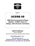
CONTROLS DESCRIPTION AND DIMENSIONS DIAGRAM
1. control for minimum voltage threshold, Umin (%);
2. control for maximum voltage threshold, Umax (%);
3. control for peak phase imbalance threshold, PI (%);
4. control of trip delay setting for Umin, Tmin (sec);
5. control of trip delay setting for the mains voltage faults,
Toff (sec);
6. control for automatic reset delay setting, Ton (sec);
7. green LED signal that the mains voltage is present, ON;
8. green LED signal that load is energized, Load;
9. red LEDs signal for the mains voltage fault/ magnetic
starter (MS) power contacts monitoring, Fault;
10. MS power contacts monitoring terminals;
11. input contacts;
12. output contacts;
13. terminals for the mode selection: line/phase voltage
monitoring.
www.novatek-electro.com
-21 APPLICATIONS
A RNPP-301 voltage control relay is designed for:
1.monitoring of the tolerable RMS phase/line voltage level (at the option of user) with independent setting
adjustments for the minimum/maximum voltage thresholds;
2.monitoring of the correct phase sequence and phase “non-coincidence” (the phases are supposed to be
coinciding when a load is energized not from two different phases but instead from one and the same phase);
3.monitoring of three phase lines for voltage presence and the mains voltage symmetry with adjustable phase
imbalance setting;
4.monitoring of the magnetic starter power contacts status at no-load and under load;
5.the load (415V/50Hz) de-energization with user-set trip delay (Toff) through the opening the magnetic starter
coil power circuit (A.C and D.C. electric circuit switching) when fault conditions occur;
6.the mains voltage quality monitoring after the relay had tripped and did reset automatically with the user-set
reset delay (Ton) upon the voltage parameters regeneration;
7.all fault conditions (not switching of the magnetic starter power contacts is included) are displayed by special
LEDs indicating the specific cause of the occurring voltage fault in the mains.
2 TECHNICAL BRIEF
Rated phase/line voltage, V …………………………………………………………………
Mains frequency, Hz ………………………………………………………………………...
Adjustable range for Umin, % of nominal value …………………………………………..
Adjustable range for Umax, % of nominal value …………………………………….……
Adjustable range for phase imbalance, % …………………………………………………
Adjustable range for Tmin, sec ……………………………………………………………..
Adjustable range for Toff, sec ……………………………………………………………….
Adjustable range for Ton, sec ………………………………………………………………
Minimum trip delay when threshold settings are reached, sec ………………………….
Reset/energization delay when the relay energizes, sec, not more than ………………
Voltage hysteresis, V ………………………………………………………………………..
Accuracy of trip threshold for voltage, V, not more than …………………………………
Phase imbalance accuracy, %, not more than ……………………………………………
Safe operating voltage, % of rated value ………………………………………………….
Power required (under load), VA, not more than …………………………………………
Maximum switched current of output contacts, A …………………………………………
Output contacts life:
• under load 5A, no less than, operations ………………………………………….
• under load 1A, no less than, operations ………………………………………….
Protection degree of:
• apparatus …………………………………………………………………………….
• terminal block ………………………………………………………………….…….
Operating temperature range, °C …………………………………………………….…….
Storage temperature, °C …………………………………………………………………….
Weight, no more than, kg ……………………………………………………………………
Case dimensions 4 modules of S-type
Mounting 35 mm DIN-rail
Mounting position as desired
240/415
45-55
5-25
5-25
5-20
0-20
0-10
0-600
0.1
0.2
5-6
3
1.5
30-130
3.0
5
100 000
1 mln.
IP40
IP20
from -35 to +55
from -45 to +70
0.200
3 DESCRIPTION
The RNPP-301 relay (hereafter "the relay") is a digital microprocessor device that provides a high degree of
reliability and accuracy. The relay doesn't require any auxiliary power supply because it is self-powered by the
three-phase voltage to be monitored. This permits the relay to keep operate capability even when only one phase is
present (in the three-phase systems with neutral). Two modes of the mains voltage monitoring can be selected at
the user's option:
The phase voltage monitoring mode
To enable phase voltage monitoring mode it's necessary to remove jumper in between terminals 8-9 and
connect neutral wire to terminal 7. This mode of operation is recommended fot the situations when for the
machinery the neutral shift is very critical (within the range of user preset values) and when phase imbalance is a
matter of a great concern.
The line voltage monitoring mode
To go into this mode of operation one needs to apply the jumper strap between terminals 8-9; in this case to
connect the neutral is not necessary. This mode of operation is recommended when the neutral drift value and
phase voltage imbalance is not important as well as for isolated neutral three-phase systems. The relay will trip
when line voltage imbalance between phases occurs.
NOTE: To keep the relay operative and informative when only one phase is present it's advisable to connect the
neutral to the terminal 7 not removing the jumper strap between terminals 8-9. In 3-Phase systems without neutral the
RNPP-301
NOVATEK-ELECTRO
-3relay keeps operational capability when at least two phases are present.
The relay is connected in parallel to load by the L1, L2, L3 input contacts (the 4, 5, 6 terminals respectively).
The neutral connection mode (N, the 7 terminal) corresponds to the mains voltage monitoring mode of operation
selected by user. The 1, 2, 3 terminals provide the MS power contacts status monitoring and are connected to the
output MS power contacts terminals (see the wiring diagram). The relay has two groups of independent output
contacts (10-11, 12-13). In the "dead status” of the relay (a voltage is not applied to the relay, the relay is not
connected) the 12-13 are the N.O. contacts and the 10-11 are N.C. contacts. After the relay has been connected
in parallel to load when voltage is present in the mains and there is no cause for the relay to trip, the 12-13 contacts
are being closed and the 10-11 contacts are being opened with the user-set reset delay Ton.
When the relay tripped, load is de-energized due to the break in the MS coil power circuit by the N. O. 12-13
contacts.
It is recommended the 12-13 contacts to connect in series with the MS coil power supply.
The 10-11, 12-13 output contacts specification
Max. current for ~ 250 VAC Max. power Max sustained safe voltage~ Max. current for U=30VDC
Cosφ = 0.4
Cosφ = 1.0
3A
5A
1200VA
460V
3A
MS power contacts transfer monitoring
One of the relay functions is the monitoring of the MS power contacts position before load energization and after
load is energized. The monitoring is performed if the 1, 2, 3 terminals are connected to the corresponding phases of
the MS output contacts. The monitoring is performed as follows:
1. Before load is energized a test for open position of all three MS power contacts is performed. If at least one
contact is closed ("sticks") the relay will be disabled, the load is not energized, all red “FAULT” LEDs are ON. To
enable the relay one needs to remove supply voltage from it. It's recommended to test the MS running order,
following safety regulations.
2. When load is energized, the test for closed position of all three MS power contacts is performed. If at least
one MS phase contact is open, the relay will trip to de-energize load and will be disabled. All red “FAULT” LEDs
are ON. To enable the relay one needs to remove supply voltage from it. It's recommended to test the MS running
order, following safety regulations.
3. When the relay trips for load de-energization, the test for open position of all three MS phase contacts is performed. If at least one contact is closed ("sticks"), the relay will energize and de-energize the magnetic starter onetwo times. If the defect is not eliminated, the relay will be disabled, all red “FAULT” LEDs will be ON. To release
the relay one needs to remove supply voltage from it. It's recommended to test the MS running order, following
safety regulations.
Indication
• the green LED «ON» is always on when at least one phase is under supply voltage;
• the green LED «Load» switches on when the load is energized (the 12-13 output terminals are closed);
• each of three LED indicators «Fault» flashes according to specific type of fault; all three LEDs flash in turn
when there is phase reversal and/or phase “coincidence”; LEDs «Umin» and «PI» are flashing when there is a
phase loss; all three LEDs are on if the relay is disabled for the MS power contacts not-switching.
Controls
The relay has six independent controls for basic parameters. For user’s convenience screwdriver slots of
adjusting potentiometers are brought out to the relay front panel.
• Umin — trip threshold for the minimum allowable voltage, % of rated voltage;
• Umax — trip threshold for the maximum allowable voltage, % of rated voltage;
• PI — phase/line voltage imbalance threshold (according to selected monitoring mode), difference between RMS
phase/line voltages, % of a lesser value;
• Tmin — trip delay for the minimum voltage that allows to ignore transient and/or starting voltage drops; it's
recommended to set Tmin no less than 10 sec.
• Toff — trip delay covering all types of the mains voltage faults, undervoltage excluded. It's recommended to set
Toff no less than 1-1,5 sec to prevent the excessive relay trippings due to switching perturbations in the mains;
• Ton — automatic reset delay after the relay tripped and the mains voltage parameters have regenerated; this is
also the energization time delay after the normal voltage was applied to the relay.
4 PRELIMINARY STARTING PROCEDURE AND SERVICE MANUAL
The relay is ready for service and needs no pre-starting procedure measures. Due to digital technology the
relay trip settings are calibrated quite accurate, so to set adjustments one doesn't need to read voltage on the
control voltmeter. In order to install the relay at the using activity after extended storage it's recommended to test
functionality of the relay. The application of the relay according to specifications above and to the present service
manual, continuous work included, allows not to carry out preventive maintenance during service life.
To put the relay in operation one must follow operating instructions given below:
NOVATEK-ELECTRO
RNPP-301
-4-
1. To set trip thresholds, trip delays and reset delay by potentiometer's contact arms.
2. To select the mains voltage monitoring mode of operation (to remove/apply a jumping strap between the 8-9
terminals).
3. To connect the relay in parallel to the mains to be monitored (the 4, 5, 6 terminals); to connect, if needed, the
neutral (the 7 terminal), to connect the relay output contacts (the 10-11,12-13 terminals) to the MS coil power circuit
(the control circuit).
4. To connect the 1, 2, 3 terminals to the MS output contacts. If there is no need in the MS power contacts
position monitoring, the connection is not effected.
5. To apply voltage to the relay.
The relay must be connected according to safety regulations.
It's recommended to set trip thresholds in the "dead" status of the relay. In testing mode it's permitted to set trip
threshold under voltage, following safety regulations
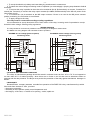
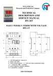
WIRING DIAGRAM
The relay should be connected in parallel to load according to the diagrams shown below.
The RNPP-301 wiring diagram with selectable mode of operation;
11 12 13
N
9 10
PROTECTED
POWER LOAD
N
N
7 8
1 2 3 4
K1 K2 K3 L1
5 6
L2 L3
11 12 13
N
7 8
9 10
L1
K
L3 N
~240V
L3
SCHEME B. Phase voltage (line-to ground)
monitoring mode
PROTECTED
POWER LOAD
K
L1
~415V
5
1 2 3 4
K1 K2 K3 L1 L2
6
L3
SCHEME A. Line voltage (phase-to-phase)
monitoring mode
5 STORAGE AND SHIPPING CONDITIONS
The relays in manufacturer package should be stored in enclosed rooms at from -45 to +70 °C and exposed to
no more than 80 % of relative humidity when there are no fumes in the air that exert a deleterious effect on
package and the relay material. The Buyer must provide the protection of the relay against mechanical damages in
transit.
6 WARRANTY
Novatek-Electro company warrants a trouble-free operation of the RNPP-301 relay manufactured by it within
36 months from the date of sale, provided:
-- the proper connection;
-- the safety of the inspection quality control department seal;
-- the integrity of the case, no traces of an opening, cracks, spalls etc.
RNPP-301
NOVATEK-ELECTRO