1
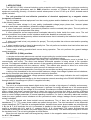
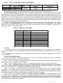
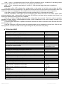
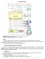
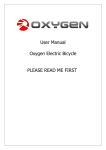
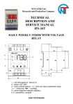
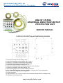
NOVATEK-ELECTRO LTD
Research-and-Manufacture Company
UBZ-301 (5-50A)
UNIVERSAL INDUCTION MOTOR
PROTECTION UNIT
SERVICE MANUAL
CONTROLS DESCRIPTION AND DIMENSIONS DIAGRAM
1. Control for nominal current setting, Inom;
2. Control for operating current setting, Iop (% Inom);
3. Control for T2 (double overload trip) delay setting;
4. Combined trip adjustment control for Umin/Umax;
5. Control for phase imbalance adjustment, PI;
6. Control for trip threshold for the minimum current, Imin (%Inom);
7. Control for automatic reset delay setting, Ton;
8. Green LED indicating for the mains voltage presence;
9,10,11. Red LEDs indicating faults for insulation, overload and U fault respectively;
12. Green LED indicating for load energization;
13. Output terminals;
14. Input terminals (10,11,12 are used for the connection with the BO-01 exchange unit);
15. Insulation monitoring terminal.
www.novatek-electro.com
-2-
1 APPLICATIONS
The UBZ-301 (5-50A) universal induction motor protection unit is designed for the continuous monitoring
of the mains voltage parameters and for RMS phase/line currents of 3-Phase AC 380V/50Hz electrical
equipment monitoring, primarily, of induction motors whose power is from 2.5 kW up to 25 kW, isolated neutral
system included.
The unit provides full and effective protection of electrical equipment by a magnetic starter
(contactor) coil control.
The unit isolates electrical equipment from the running system and/or disables its start. This is performed
in the following cases:
1. when the mains voltage is of poor quality (unallowable voltage jumps, phase loss, incorrect phase
sequence and phase «coincidence», phase/line voltage imbalance);
2. when mechanical overloads (symmetrical phase/line current overload) take place. The unit performs
overload protection with a dependent time delay;
3. when phase/line current asymmetrical overloads induced by faults inside the motor occur. The unit
performs protection from phase current imbalance and further disables an automatic reset;
4. when phase current asymmetry without overload occurs that is induced by the insulation fault inside the
motor and/or the power cable;
5. when motor load is lost («dry stroke» for pumps). The unit provides the minimum start and/or operating
current protection;
6. when insulation level to frame is abnormally low. The unit performs insulation level test before start and
if the insulation is poor the start is disabled.
7.when stator winding ground-to-fault occurs during operation. The unit performs the ground leakage
current protection.
The UBZ-301 (5-50A) provides:
• a simple and accurate electromotor nominal current setting by nominal current standard scale;
• the electromotor operating current setting that differs from standard values;
• overload tripping with a dependent time delay (the current-time characteristic curve is plotted for a
conventionally cold motor). The motor heat balance differential equation is being solved in the operation
process. This approach enables to take account of the preceding electromotor status and to make a decision
on heat overload presence with the maximum validity. This method also permits to allow for a motor start
heating and to restrict (at the customer’s option) amount of starts per unit time;
• shift of current-time characteristic curve along the current-axis and along time-axis as well;
• setting of trip thresholds for the minimum/the maximum voltage, line voltage & phase current imbalance,
and also for automatic reset delay at the personal customer’s discretion;
• fault type indication, the mains voltage presence indication, current range indication the unit is adjusted
to, and load energization indication;
• the data exchange and transfer to the local computer network according to the RS-485 MODBUS record
through the BO-01 exchange unit (BO-01 is supplied on order).
2 DESCRIPTION
The unit is a microprocessor-based digital device that provides a high degree of reliability and accuracy.
The unit doesn’t need any auxiliary supply because it retrieves it's energy demand out of the measurement
signal: it’s self-powered by the voltage to be monitored. Simultaneous isolated independent monitoring for the
mains voltage and phase currents permits to detect the type of occurring fault and to provide a different
decision-making logic for each fault type. When the mains voltage faults occur the unit performs automatic load
reset on return voltage parameters to normal operating conditions. If a fault is induced by abnormal condition
inside the motor (phase current imbalance at the symmetrical mains voltage, leakage current presence etc.)
restart is disabled.
The unit is stocked with three toroidal current transducers. Two of them are the phase/line current
transducers (TT1, TT2), power phase cables are pulled through them. The third transducer is the differential
current transducer (DCT) that has an enlarged diameter, because three power phase cables are pulled through
it. By the 6, 7, 8, 9 terminals the unit is connected in parallel to the mains supply to be monitored. The unit
output is provided with N.O. and N. C. contacts (the 1, 2, 3, 4 terminals). The output 3-4 terminals are
connected in series with the starter coil power supply (with control circuit). The 5 terminal is designed to monitor
the insulation level. The unit wiring diagram is shown below.
When the unit trips the load is de-energized by a break in the magnetic starter coil power circuit through
the N. C. 3-4 contacts.
UBZ-301 63-630 A
NOVATEK-ELECTRO
-3-
Table 1 - The 1-2-3-4 output contacts specification
Cosφ = 0.4
Cosφ = 1.0
Max. current for
Max. power
~ 250 V A. C.
3A
2000VA
Max sustained safe
voltage ~
Max. current for
U = 30V D.C.
460V
3A
5A
Nominal parameters and trip thresholds are set by front-panel screwdriver potentiometers.
Nominal current setting. Nominal current is set by № 1 potentiometer. There are eleven positions of the
potentiometer. Each position corresponds to the specific standard nominal current scale value (see below
Table of Nominal Currents). Each position is characterized by the specific number of blinks that the green «On»
LED makes. To set the nominal current one needs to bring out potentiometer control arm to a corresponding
position; when the unit is energized the number of blinks «On» LED must correspond to the Table below. One
needs to take into account that there are «dead bands» between the positions where «On» LED glows without
blinks and where the nominal current is indefinite.
In order to set operating value which is different from the nominal one that is specified in the nominal
current table, it’s recommended the № 1 potentiometer to set to the position corresponding to the nearest
value from the nominal current scale, and by the № 2 potentiometer one can increase or decrease the
necessary value in % from the set value.
Table 2 - Nominal current table
Potentiometer
№1 devisions
1
2
3
4
5
6
7
8
9
10
11
Nom.
current, А
5
6,3
8
10
12.5
16
20
25
32
40
50
Green LED «On» blink
1bl.- pause
2bl.- pause
3bl.- pause
4bl.- pause
5bl.- pause
6bl.- pause
7bl.- pause
8bl.- pause
9bl.- pause
10bl.- pause
11bl.- pause
NOTES:
1. Continuous green «On» LED glow means that the potentiometer is set in «dead band». One needs to
set the potentiometer so as the green LED blinked and the number of blinks corresponded to the set nominal
current.
2. Nominal currents setting is to be performed correcting for load connections (Wye/Delta), according to
ratings of engine.
Controls and adjustments
The unit has seven independent controls. For user’s convenience screwdriver slots of adjusting
potentiometers are brought out to the unit front panel.
• №1 – «Inom» - nominal current setting; there are eleven positions and each position corresponds to the
specific current from the nominal currents table;
• №2 – «Iop» - operating current; it is set in ± 15 percent of nominal current, it has ten scale marks;
• №3 – «T2» - overload trip delay when there is double overload for operating current set; in the central
position T2 ≈ 58-60 seconds The minimum time delay is 10 seconds, the maximum time delay is 100 seconds.
The control shifts current-time characteristic dependence along time axis;
• №4 – «Unom(%)» - combined control for Umax/Umin threshold in percent of the nominal voltage;
according to this setting before the load energization the unit is checking the mains voltage level and,
depending on its value, permits or forbids the load energization; after the load has been energized the voltage
monitoring is going on but the load de-energization decision is made for currents;
• №5 – «PI%» - trip threshold control for line voltage imbalance and RMS phase current imbalance; it has
ten scale marks. The parameter is calculated as the difference between the maximum and the minimum values,
in percent of the maximum value. If current imbalance percentage is twice as much as voltage imbalance
percentage then it’s supposed that the imbalance is induced by fault conditions inside the motor. The automatic
reset is forbidden and the unit is disabled;
NOVATEK-ELECTRO
UBZ-301 63-630 A
-4• №6 – «Imin» - trip threshold control for the minimum operating current, in percent of operating current
set. It has ten scale marks from 0% to 75%: in «0» position this control is off;
• №7 – «Ton» - automatic reset delay, it is within 0 – 600 seconds range; the scale is logarithmic.
Indication
• the green «ON» LED indicates that voltage exists in the mains. In the blink mode of glow the blink
number between pauses corresponds to the specific nominal current from the nominal current table; there is a
continuous glow in a «dead band». One needs to set a nominal current in the blink mode of operation;
• the green «Load» LED indicates that the load is energized (the 3-4 terminals are closed);
• the red «Insulation» LED lights up with continuous glow before the start if the stator/ power cable
winding insulation level is abnormally low (less than 500 kOhms), and also during operation when there is a
tripping for differential current; the unit is disabled;
• the red «U Fault» LED glows when the mains voltage fault has occurred. The blink mode of operation
switches on when there is undervoltage/overvoltage, phase imbalance for the mains voltage, voltage is not
present on all three phases;
• incorrect phase sequence or phase coincidence induces the mode of operation when all three red LEDs
are blinking in turn;
• the red «Overload» LED blinks when the average phase current exceeds the nominal one. After the unit
has tripped for overload this LED comes to glow during 0.9 AR (automatic reset) delay.
4 TECHNICAL BRIEF
Nominal line voltage, V
Mains frequency, Hz
Nominal current range in UBZ-301 5-50, А
Operating current setting range, % of nominal
Double overload delay adjustment range, sec
Voltage threshold adjustment range, % of nominal
Phase imbalance adjustment range, %
Trip threshold adjustment range for the minimum current, % of nominal
Automatic reset delay adjustment range ( Тon), sec
First energization load delay when Тon= 0, sec
Trip delay for current overload
Trip delay for voltage fault, sec
Trip delay for current fault (overload excluded), sec
Fixed trip point for leakage current, А
Insulation resistance threshold, kОhms
Voltage hysteresis, V
Heat hysteresis, % of stored-up heat after load de-energization
Trip threshold accuracy for current, % of nominal current, not more than
Trip threshold accuracy for voltage, V, not more than
Phase imbalance accuracy, %, not more than
Operating voltage range, % of nominal one
Power consumption (under load), VA, not more than
Maximum switched current of output contacts, A
Output contact life:
- under 5A load , operations, no less than
- under 1A load , operations, no less than
Enclosure:
- apparatus
- terminal block
Operating temperature range, °C
Storage temperature, °C
Weight, kg, not more than
Case dimensions 4 modules of S-type
Mounting standard 35 mm DIN-rail
Mounting position arbitrary
UBZ-301 63-630 A
380
45-55
5-50
±15
10-100
±(5-20)
5-20
0-75
0-600
2-3
According to current-time
characteristic curve
2
2
0.5
500±20
10/17
33
2-3
3
1.5
50-150
3.0
5
100 000
1 000 000
IP40
IP20
from -35 to +55
from -45 to +70
0.200
NOVATEK-ELECTRO
-5-
5 OPERATION
1. After supply voltage has been applied to the unit and before the output relay is energized the unit
checks:
• a stator winding insulation level to frame. If insulation resistance is below 500±20 kOhms, the load is not
energized. The red «Insulation» LED glows;
• the mains voltage quality, i. e. if voltage is present on all three phases, if the mains voltage is
symmetrical, what the RMS line voltage value is like. When any of inhibit factors is present, the load is not
energized, the red «U Fault» LED blinks;
• a correct phase sequence, and phase «non-coincidence». When any of inhibit factors is present, the
load is not energized, all red LEDs are blinking in turn; If all the parameters are normal, the outlet relay will be
energized after Ton delay has expired (the 3-4 contacts are being closed and the 1-2 contacts are being
opened) - the green «Load» LED glows. If load currents are absent (there are no less 2% of nominal one) the
reason is that the load is de-energized. Voltage monitoring and insulation level is going. Output relay of unit is
de-energized if inhibit factors are present in pause without currents;
2. After the load is energized the unit performs voltage and current monitoring. The decision on load deenergization is made according to the following factors:
• RMS current exceeds the nominal (operating) current (set by №№ 1, 2, 3 potentiometers); if there is
current overload without heat overload the red «Overload» LED blinks but the load is not de-energized. If
current overload induces heat overload the load is de-energized. The red «Overload»LED glows and is ON
during 0.9Ton. The automatic reset is permitted;
• current imbalance (set by №5 potentiometer) is twice exceeds the mains voltage imbalance; the load is
de-energized, all red LEDs glow, the unit is disabled, the automatic reset is forbidden. To enable the unit one
needs to remove supply voltage from the unit. It’s supposed that this type of fault is induced by abnormal
conditions inside the motor;
• current imbalance (set by №5 potentiometer) is less than twice exceeds voltage imbalance; the load is
de-energized, the red «U Fault» LED glows, the automatic reset is permitted;
• current imbalance (set by №5 potentiometer) is less than voltage imbalance; the load is de-energized,
the red «U Fault» LED blinks, the automatic reset is permitted;
• the average current value is less than Imin (set by №6 potentiometer); the load is de-energized, all red
LEDs blink simultaneously, the unit is disabled, the automatic reset is forbidden. To enable the unit one needs
to remove the supply voltage from the unit.
Electromotor protection against heat overload
The electromotor heat balance equation is being solved as the work advances. It’s supposed that:
• the motor was cold before start;
• during operation the motor releases the heat which is proportional to the current square;
• after the stop the motor cools down exponentially.
Below is the current-time characteristic curve with different T2 values (set by №3 potentiometer), where:
• I/In – current ratio relative to the nominal current;
• T/T2 -- actual trip delay relative to T2 (set by № 3 potentiometer).
Current-time characteristic dependence
NOVATEK-ELECTRO
UBZ-301 63-630 A
-6-
The current-time characteristic dependence shown in the tables below is given for the standard
recommended T2 value (the №3 potentiometer middle position corresponds to 60 seconds when double
overload occurs):
I/Inom
Тsec
heat;
1.1
365
1.2
247
1.4
148
1.7
88.6
2
60
2.7
36.4
3
24.6
4
13.5
5
8.5
6
5.9
7
4.3
8
3.3
10
2.1
15
0.9
After the load has been de-energized owing to the heat overload it will automatically be energized again:
• according to heat hysteresis if time delay Ton=0, i. e. the motor must cool down 33% of the stored up
• according time delay Ton (№ 7 potentiometer) if Ton isn’t equal 0.
By suitable selection of different Ton values, heat hysteresis considered, one can reduce number of starts
per time unit because in the intermittent cycle the unit stores heat quantity released at the start of the motor.
6 PRELIMINARY STARTING PROCEDURE AND SERVICE MANUAL
The unit produced is completely ready for operation and needs no special pre-starting procedure
measures. Owing to digital technology all the unit settings are aligned quite accurate, so no control devices are
needed to adjust them. Use of the unit according to specifications above and the present service manual,
continuous work included, relieves of preventive maintenance during service life. To put the unit in operation
one must follow operating instructions given below:
1. To set nominal (operating) current, trip thresholds, trip delays and reset delay by potentiometer's
contact arms.
2. To connect the unit according to the wire diagram given below:
• by the 6(L1), 7(L2), 8(L3), 9(N) terminals the unit is connected in parallel to the mains supply to be
monitored;
• two current transducers (each one of them is put on two power phase wires that carry the load) are
connected to the 13, 14, 15, 16 terminals; in connecting one has to consider the transducers grading;
1st transducer– the beginning – the 13 terminal, the end – the 14 terminal;
2nd transducer– the beginning – the 15 terminal, the end – the 15 terminal;
• a differential current transducer that is put on the three power phase wires must be connected to the 17,
18 terminals (the connection grading is unimportant);
• the 5 insulation monitoring terminal is connected to one of the MS output contacts;
• output contacts (the 3-4 terminals) are connected to the MS coil power supply circuit (control circuit);
• the BO-01 exhange and date transfer unit is connected to the 10, 11, 12 terminals (this unit is supplied
on order).
3. To apply a voltage to the unit. The correct setting of nominal current is checked by the number of
blinks that the green LED makes. After Ton has expired (if there are no factors that can forbid energizing) the
output relay of the unit is energized. If Ton=0, the first energizing will occur after 2-3 sec delay has expired.
NOTE - The unit must be connected subject to the safety regulations. To set settings is recommended in
«off» state. To set settings alive is permitted in the test conditions subject to the safety regulations.
ATTENTION! If immediately after the load has been energized the unit de-energizes it and disables
it for current imbalance, the incorrect polarity of the current transducers TT1 or TT2 connection may be
a reason. Then it’s recommended to change one of the transducers connection by reversing the places
“the beginning- the end” of the 13-16 terminals. If the effect pointed above repeats when the load is reenergized it means that the transducers were connected correctly and the imbalance arose from EM
and/or power cable fault.
NOTES:
1 Transducers are mounted by plastic clamps (they are component parts of supplies).
2 The phase wires which are passing through the differential transducer to try to symmetrize in the center of the
transducer.
UBZ-301 63-630 A
NOVATEK-ELECTRO
-7-
WIRING DIAGRAM
DT–differential current transducer (differential current transformer);
CT1,CT2–current--transducers;
BO-01– exchange and date transfer unit (on order)
NOTE:
1 “START”-button and “STOP”-button can be connected to MSC power supply circuit if necessary;
2 The 220V MSC connection is shown here. The 380V MSC power supply circuit is analogous, coil power
is applied from different phases through the 3-4 contacts;
3 If BO-01 is absent the 10, 11, 12 terminals are not used.
7 STORAGE AND SHIPPING CONDITIONS
The unit in manufacturer package should be stored in enclosed rooms at –45 to +70 °C and
exposed to no more than 80% of relative humidity when there are no fumes in the air that exert a
deleterious effect on package and the unit material. The Buyer must provide the protection of the unit
against mechanical damages in transit.
8 WARRANTY
Novatek-Electro LTD. Company warrants a trouble-free operation of the UBZ-301 (5-50A) unit
manufactured by it within 36 months from the date of sale, provided:
• the proper installation;
• the safety of the inspection quality control department seal;
• the integrity of the case, no traces of an opening, cracks, spalls etc.
NOVATEK-ELECTRO
UBZ-301 63-630 A