1
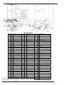
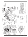
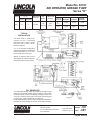
Model No. 83167
AIR OPERATED GREASE PUMP
Series "H"
RATIO
40:1
LUBRICANT OUTPUT
RESERVOIR AIR
(cu. in.)
PER
PER MIN. CAPACITY INLET
CYCLE (@100PSI)
*.11
12
12 LBS.
1/8"
NPTF(F)
LUBRICANT
OUTLET
3/4"
NPTF(F)
LUBRICANT OPERATING PRESSURE (PSI)
TYPE OF
SYSTEM
SL-1
SL-11
SL-32
SL-33
RECOMMENDED
MINIMUM
MAXIMUM
1,850
3,550
2,500
1,200
3,550
1,500
TYPICAL
INSTALLATION
The 83167 Pump is used as the
pumping unit for a centralized
lubrication system having a single
line circuit of SL-1, SLS-11, SL-32,
OR SL-33 Injectors.
It is an air operated reciprocating
pump that discharges an established
amount of lubricant *(.11 cu. in.) into
the circuit for each pump cycle.
*Based on lubricants that are free
of entrapped air. Lubricants that are
aerated will reduce output of pump.
FILL RESERVOIR
Use 81834 Manual Filler Pump to fill reservoir through the filler
fitting in the pump body. Attach coupler on delivery hose to filler.
Stroke filler pump handle until lubricant weepage is noted at air
vent hole in reservoir (lower portion of follower must rise beyond
air vent hole to expel entrapped air from lubricant).
NOTE: When filling the reservoir, caution should be used as extreme
pressure can cause damage to reservoir and follower assembly.
One Lincoln Way
St. Louis, Missouri 63120-1578
(314) 679-4200
JULY - 2005
Copyright 2005
Printed in U.S.A.
- C8
- 85T
Section
Page
FORM 403574
©
SERVICE PARTS
Part
Qty. Description
#*10061
1
Pump check disc
10127
1
10772
Qty. Description
Part
Qty. Description
#*34158
1
Gasket (Neoprene)
68797
1
Plug button
Plug
34166
1
O-ring (Nitrile)
69034
1
Retaining ring
1
Nipple
*34229
1
Packing (Nitrile)
69181
1
Lockwasher
11470
1
Cap
34308
1
Gasket (Nitrile)
#*83063
1
Valve slide, seat & gasket assembly
#*11471
1
Trip rod collar
#*34314
1
O-ring (Nitrile)
83948
1
Vent valve assembly
#*11472
1
Trip rod pin
34438
1
Follower
84508
1
Bushing, plunger & O-ring assembly
#*11475
1
Trip shoe
#*38162
1
Valve gasket (Nitrile)
#*90770
1
Trip rod
11904
1
Packing nut
40821
1
Base casting
*90942
1
Safety unloader
11905
1
Packing cap
#*45605
1
Valve guide plate
#*91331S
1
Toggle plate
#*11947
1
Trip sleeve
48140
1
Washer
91817
1
Reservoir cap
12093
1
Check housing
48212
2
Washer
92242
1
Bushing & washer assembly
12094
1
Air piston bolt
48216
1
Washer
92441
1
Filler fitting
12095
1
Outlet body
48237
1
Washer
236286
1
Cover
12096
1
Outlet block
48417
1
Follower washer
12511
2
Pipe plug
50000
6
Screw
12834
1
Spring retainer
50086
1
Bolt
13808
1
Adapter
50521
4
Screw
14449
1
Tie rod
51039
1
14491
1
Retainer washer
51099
1
14720
1
Air cylinder
55138
14721
1
Piston
*14722
1
*14723
1
14727
236615
1
Muffler cover
#*236616
1
Gasket
236833
1
Muffler
#*236835
1
Packing (Nitrile)
Nut
236868
4
Screw
Nut
236869
6
Screw
4
Spring
236870
4
Valve seat bolt
55231
1
Spring
237562
1
Air valve casting
Needle
55346
1
Follower spring
239330
1
Viton packing assembly
Valve seat
#56003
1
Spring
239336
1
Valve body
1
Reducer nipple
#56038
2
Spring
#*244313
1
Seat
O-ring (Nitrile)
16471
1
Support adapter
66002
1
Steel ball
#*244359
1
#30003
1
Gasket
#*66010
2
Steel ball
#*245425
1
Trip rod packing nut
#*31007
2
Gasket
66186
1
Lockwasher
#246816
1
Gasket
31047
2
Gasket
66200
1
Straight tube connector
247244
1
Reservoir (acrylic)
31054
1
Gasket
66201
1
90 degree tube connector
#247611
1
Gasket
#31056
1
Gasket (Nitrile coated fiber)
66210
1
90 degree tube connector
247763
1
Nylon tubing
#*33039
1
Gasket (Nitrile)
66211
1
Straight tube connector
272724
1
Nylon tubing
34090
1
Packing (Nitrile)
66246
6
Lockwasher
360383
1
Base
#34110
1
Packing (Nitrile)
67011
1
Tee
361066
1
Bracket
*34122
1
Check disc packing
68528
1
Strainer
633102
1
Plug
274225©
1
Retaining Ring
© Indicates Change
*Recommended Service Parts Inventory.
Page 2
Part
Form 403574
#Included in 246415 repair kit.
Form 403547
Page 3
247611
Replace cover gasket, cover and screws. Tighten to avoid air
leaks.
Use NLGI No. 1 (light grade) water repellent grease.
Approximately
1 1/2 ounces.
Before replacing the toggle assembly, pack cavity with grease.
The air valve casting should be cleaned or flushed to remove any
chips, or other foreign particles prior to re-assembly.
Remove and disassemble the air valve casting from the pump.
Disconnect air to pump, remove the four cover screws, cover plate
and cover gasket.
TO LUBRICATE
AIR VALVE MECHANISM
INSTRUCTIONS FOR PUMP USING 85209 CONTROL PANEL
TO PRIME SYSTEM
SUPPLY LINES:
After pump reservoir has been filled with recommended lubricant,
loosen all plugs in dead ends of injector manifolds and supply lines.
Turn vent plug in pump counter-clockwise one complete turn. Depress
manual lube pushbutton on door to start pump. Operate pump until
lubricant bleeds around vent plug to expel air pockets trapped between
the pump and the supply line connection. Tighten vent plug. continue
operating pump unitl lubricant flows around any plug. Tighten plug.
Repeat this procedure until all plug openings are tight and supply lines
are primed. Turn off power to reset controller.
IMPORTANT:
Refer to Owner/Operator Manual C8 259 to program controller on
85209.
INJECTORS:
Check the injectors for proper operation by observing the movement
of the indicator stems.
OPERATION:
When model 85530 times out it will initiate a lube cycle. The air
solenoid is energized to deliver air to the pump and air to the vent
valve. Pump begins dispensing lubricant through injectors to the
bearings.
When all bearings have received lubricant, pressure rises in system
to actuate pressure switch. When pressure switch actuates, the
control is reset to de-energize solenoid valve cutting off air to pump
and vent valve. Pump stops, pressure vents and pressure switch
de-actuates. Control begins timing toward next lube event.
FEEDER LINES:
Fill each feed line with lubricant before connecting lines to outlets of
injectors and bearings. This will prevent having to cycle each injector
to fill the feed line between injector and bearing.
INSTRUCTIONS FOR PUMP USING 83820 TIME CONTROL
TO PRIME SYSTEM
SUPPLY LINES:
After pump reservoir has been filled with recommended lubricant,
loosen all plugs in dead ends of injectors manifolds and supply lines.
Turn vent plug in pump counter-clockwise one complete turn. Set the
delay relay to its maximum position (Refer to Service Manual Section
C8, Page 133 Sefies). Depress push button on top of time control
to start pump. Operate pump until lubricant bleeds around vent
plug to expel air pockets trapped between the pump and the supply
line connection. Tighten vent plug. Continue operating pump until
lubricant flows around any plug. Tighten plug. Repeat this procedure
until all plug openings are tight and supply lines are primed. Open
line switch to shut off pump.
IMPORTANT:
Reset the delay relay to desired interval (Refer to System Planning
Manual).
FEEDER LINES:
Fill each line with lubricant before connecting lines to outlets of
injectors and bearings. This will prevent having to cycle each injector
to fill the feed line between injector and bearing.
INJECTORS:
Check injectors for proper operation by observing the movement of
the indicator stems.
VENT VALVE:
The 83948 Vent Valve is operated by compressed air from the same
source which operates the pump. When pump is in operation, air
pressure keeps the vent valve closed and lubricant is directed through the
outlet and to the injectors. When air to the pump is shut off, vent valve
opens and supply line pressure vents back into the reservoir.
SAFETY UNLOADER:
90942 Safety unloader is provided at the pump outlet to prevent
the build-up of dangerously high lubricant pressure in the system. It
is factory set to open at approximately 3,750 psi to 4,250 psi.
NOTE: Safety unloader requires no adjustment and should not be
tamperedwith.
OPERATION
The timer (runs constantly when current is on), drives a cam which
has lobes set for the desired lubrication cycle frequency (Refer to
Service Manual Section C8, Page 133 Series). Lobes engage the
micro-switch lever arm to activate the switch, closing the circuit to
open the 3-way solenoid air valve permitting air to operate the pump.
The pump discharges lubricant through the supply line to the injectors.
After the injectors operate (discharge lubricant to the bearings), pump
continues to build up lubricant pressure in the supply line until sufficient
to operate the pressure control which moves a switch plate, breaking
the circuit to the 3-way, solenoid air valve, shutting off the air to the
pump. Injectors automatically, re-charge with lubricant and system
is ready for the next lubrication cycle.
The pressure control is factory set for 2,500 psi, adequate for any normal
installation. If higher pressure is necessary (2,900 psi maximum), the
pressure control can be reset;
1) Loosen locknut.
2) Turn the housing clockwise into the pressure control body until
proper pressure is obtained.
3) Tighten locknut.
To lower pressure (1,500 psi minimum);
1) Loose locknut.
2) Turn the housing counter-clockwise into the pressure control
body until proper pressure is obtained.
3) Tighten locknut.
WHAT TO DO IF:
Pump loses prime: Check lubricant supply.
10127 Vent Plug is provided at the pump outlet for expelling air which
may be pocketed in the lubricant. If pump operated continuously
without discharging lubricant, it is an indication that the pump has lost
its prime. Loosen the vent plug one turn until trapped air is pumped out.
If pump continues to operate without discharging lubricant, 10061 Pump
Check and 66002 Steel Ball may be fouled. Remove and clean checks
and check seats. The 83948 VentValve may also be fouled. Foreign
material may prevent 14722 Needle from seating proper]), or 14723
Valve Seat may be worn or damaged. Clean or replace parts.
Failure of injectors to cycle can also be caused by a leak in the supply
line. Examine lines and connections.
Pump fails to operate: Check air supply.
RETAIN THIS INFORMATION FOR FUTURE REFERENCE
When ordering replacement parts, list: Part Number, Description, Model Number and Series Letter.
LINCOLN provides a Distributor Network that stocks equipment and replacement parts.
Page 4
Form 403574