1
Keysight 8498A
Fixed Attenuator
Operating and
Service Manual
Notice
The information contained in this document is subject to change without
notice.
Keysight Technologies makes no warranty of any kind with regard to this
material, including, but not limited to, the implied warranties of
merchantability and fitness for a particular purpose. Keysight
Technologies shall not be liable for errors contained herein or for
incidental or consequential damages in connection with the furnishing,
performance, or use of this material.
Keysight Technologies assumes no responsibility for the use or reliability
of its software on equipment that is not furnished by Keysight
Technologies.
This document contains proprietary information which is protected by
copyright. All rights are reserved. No part of this document may be
photocopied, reproduced, or translated to another language without prior
written consent of Keysight Technologies.
Restricted Rights Legend
Use, duplication, or disclosure by the U.S. Government is subject to
restrictions as set forth in subparagraph (c)(1)(ii) of the Rights in Technical
Data and Computer Software clause at DFARS 252.227-7013 for DOD
agencies, and subparagraphs (c)(1) and (c)(2) of the Commercial Computer
Software Restricted Rights clause at FAR 52.227-19 for other agencies.
The contents of this manual apply to instruments with serial number prefix
US91 and above.
Keysight Technologies
Santa Rosa Systems Division
1400 Fountaingrove Parkway
Santa Rosa, CA 95403-1799, U.S.A.
ii Keysight Technologies 8498 Operating and Service Manual
Warranty
Certification
Keysight Technologies certifies that this product met its published specifications at the time
of shipment from the factory. Keysight Technologies further certifies that its calibration
measurements are traceable to the United States National Institute of Standards and
Technology (NIST, formerly NBS), to the extent allowed by the Institute’s calibration facility,
and to the calibration facilities of other International Standards Organization members.
Warranty
This Keysight Technologies system product is warranted against defects in
materials and workmanship for a period corresponding to the individual
warranty periods of its component products. Instruments are warranted for a
period of one year. During the warranty period, Keysight Technologies will,
at its option, either repair or replace products that prove to be defective.
Warranty service for products installed by Keysight Technologies and
certain other products designated by Keysight Technologies will be
performed at Buyer’s facility at no charge within Keysight Technologies
service travel areas. Outside Keysight Technologies service travel areas,
warranty service will be performed at Buyer’s facility only upon Keysight
Technologies’s prior agreement and Buyer shall pay Keysight
Technologies’s round trip travel expenses. In all other areas, products must
be returned to a service facility designated by Keysight Technologies.
For products returned to Keysight Technologies for warranty service, Buyer
shall prepay shipping charges to Keysight Technologies and Keysight
Technologies shall pay shipping charges to return the product to Buyer.
However, Buyer shall pay all shipping charges, duties, and taxes for products
returned to Keysight Technologies from another country.
Keysight Technologies warrants that its software and firmware designated
by Keysight Technologies for use with an instrument will execute its
programming instructions when properly installed on that instrument.
Keysight Technologies does not warrant that the operation of the
instrument, or software, or firmware will be uninterrupted or error free.
LIMITATION OF WARRANTY. The foregoing warranty shall not apply
to defects resulting from improper or inadequate maintenance by Buyer,
Buyer-supplied software or interfacing, unauthorized modification or
misuse, operation outside of the environmental specifications for the
product, or improper site preparation or maintenance.
NO OTHER WARRANTY IS EXPRESSED OR IMPLIED.
KEYSIGHT TECHNOLOGIES SPECIFICALLY DISCLAIMS THE
IMPLIED WARRANTIES OR MERCHANTABILITY AND
FITNESS FOR A PARTICULAR PURPOSE.
Keysight Technologies 8498 Operating and Service Manual iii
EXCLUSIVE REMEDIES. THE REMEDIES PROVIDED HEREIN ARE
BUYER’S SOLE AND EXCLUSIVE REMEDIES. KEYSIGHT
TECHNOLOGIES SHALL NOT BE LIABLE FOR ANY DIRECT,
INDIRECT, SPECIAL, INCIDENTAL, OR CONSEQUENTIAL
DAMAGES, WHETHER BASED ON CONTRACT, TORT, OR ANY
OTHER LEGAL THEORY.
Assistance
Product maintenance agreements and other customer assistance agreements
are available for Keysight Technologies products.
For assistance, call your local Keysight Technologies Sales and Service
Office (refer to “Service and Support” on page v).
iv Keysight Technologies 8498 Operating and Service Manual
Service and Support
By internet, phone, or fax, get assistance with all your test and measurement
needs.
Online assistance: www.keysight.com/find/assist
United States
(tel) 1 800 452 4844
Latin America
(tel) (305) 269 7500
(fax) (305) 269 7599
Canada
(tel) 1 877 894 4414
(fax) (905) 282-6495
Europe
(tel) (+31) 20 547 2323
(fax) (+31) 20 547 2390
New Zealand
(tel) 0 800 738 378
(fax) (+64) 4 495 8950
Japan
(tel) (+81) 426 56 7832
(fax) (+81) 426 56 7840
Australia
(tel) 1 800 629 485
(fax) (+61) 3 9210 5947
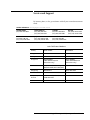
Asia Call Center Numbers
Country
Phone Number
Fax Number
Singapore
1-800-375-8100
(65) 836-0252
Malaysia
1-800-828-848
1-800-801664
Philippines
(632) 8426802
1-800-16510170 (PLDT
Subscriber Only)
(632) 8426809
1-800-16510288 (PLDT
Subscriber Only)
Thailand
(088) 226-008 (outside Bangkok)
(662) 661-3999 (within Bangkok)
(66) 1-661-3714
Hong Kong
800-930-871
(852) 2506 9233
Taiwan
0800-047-866
(886) 2 25456723
People’s Republic
of China
800-810-0189 (preferred)
10800-650-0021
10800-650-0121
India
1-600-11-2929
000-800-650-1101
Keysight Technologies 8498 Operating and Service Manual v
Safety and Regulatory Information
Review this product and related documentation to familiarize yourself with
safety markings and instructions before you operate the instrument. This
product has been designed and tested in accordance with international
standards.
WARNING
The WARNING notice denotes a hazard. It calls attention to a procedure,
practice, or the like, that, if not correctly performed or adhered to, could result
in personal injury. Do not proceed beyond a WARNING notice until the
indicated conditions are fully understood and met.
CAUTION
The CAUTION notice denotes a hazard. It calls attention to an operating
procedure, practice, or the like, which, if not correctly performed or adhered
to, could result in damage to the product or loss of important data. Do not
proceed beyond a CAUTION notice until the indicated conditions are fully
understood and met.
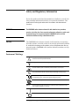
Instrument Markings
!
When you see this symbol on your instrument, you should refer to the instrument’s
instruction manual for important information.
This symbol indicates hazardous voltages.
The laser radiation symbol is marked on products that have a laser output.
This symbol indicates that the instrument requires alternating current (ac) input.
The CE mark is a registered trademark of the European Community. If it is
accompanied by a year, it indicates the year the design was proven.
The CSA mark is a registered trademark of the Canadian Standards Association.
1SM1-A
This text indicates that the instrument is an Industrial Scientific and Medical Group 1
Class A product (CISPER 11, Clause 4).
This symbol indicates that the power line switch is ON.
This symbol indicates that the power line switch is OFF or in STANDBY position.
vi Keysight Technologies 8498 Operating and Service Manual
Safety and Regulatory Information
Safety Earth
Ground
This is a Safety Class I product (provided with a protective earthing
terminal). An uninterruptible safety earth ground must be provided from the
main power source to the product input wiring terminals, power cord, or
supplied power cord set. Whenever it is likely that the protection has been
impaired, the product must be made inoperative and secured against any
unintended operation.
Before Applying Power
Verify that the product is configured to match the available main power
source as described in the input power configuration instructions in this
manual. If this product is to be powered by autotransformer, make sure the
common terminal is connected to the neutral (grounded) side of the ac power
supply.
Keysight Technologies 8498 Operating and Service Manual vii
Typeface Conventions
Typeface Conventions
•
Used to emphasize important information:
Use this software only with the xxxxxX system.
•
Used for the title of a publication:
Refer to the xxxxxX System-Level User’s Guide.
•
Used to indicate a variable:
Type LOAD BIN filename.
Instrument Display
•
Used to show on-screen prompts and messages that you will see on the
display of an instrument:
The xxxxxX will display the message CAL1 SAVED.
[Keycap]
•
Used for labeled keys on the front panel of an instrument or on a
computer keyboard:
Press [Return].
{Softkey}
•
Used for simulated keys that appear on an instrument display:
Press {Prior Menu}.
User Entry
•
Used to indicate text that you will enter using the computer keyboard;
text shown in this typeface must be typed exactly as printed:
Type LOAD PARMFILE
•
Used for examples of programming code:
Italics
#endif // ifndef NO_CLASS
Path Name
•
Used for a subdirectory name or file path:
Edit the file usr/local/bin/sample.txt
Computer Display
•
Used to show messages, prompts, and window labels that appear on a
computer monitor:
The Edit Parameters window will appear on the screen.
•
Used for menus, lists, dialog boxes, and button boxes on a computer
monitor from which you make selections using the mouse or keyboard:
Double-click EXIT to quit the program.
viii Keysight Technologies 8498 Operating and Service Manual
Contents
Notice . . . . . . . . . . . . . . . . . . . . . . . . . . . . . . . . . . . . . . . . . . . . . . . . . . . . . iii
Warranty . . . . . . . . . . . . . . . . . . . . . . . . . . . . . . . . . . . . . . . . . . . . . . . . . . . iii
Certification . . . . . . . . . . . . . . . . . . . . . . . . . . . . . . . . . . . . . . . . . . . . . iii
Assistance . . . . . . . . . . . . . . . . . . . . . . . . . . . . . . . . . . . . . . . . . . . . . . . iv
Service and Support . . . . . . . . . . . . . . . . . . . . . . . . . . . . . . . . . . . . . . . . . . .v
Safety and Regulatory Information . . . . . . . . . . . . . . . . . . . . . . . . . . . . . . . vi
Safety Earth Ground . . . . . . . . . . . . . . . . . . . . . . . . . . . . . . . . . . . . . . vii
Before Applying Power . . . . . . . . . . . . . . . . . . . . . . . . . . . . . . . . . . . .vii
Typeface Conventions . . . . . . . . . . . . . . . . . . . . . . . . . . . . . . . . . . . . . . . viii
General Information . . . . . . . . . . . . . . . . . . . . . . . . . . . . . . . . . . . . . . . . . . 1
Attenuator Overview . . . . . . . . . . . . . . . . . . . . . . . . . . . . . . . . . . . . . . 1
Safety Considerations . . . . . . . . . . . . . . . . . . . . . . . . . . . . . . . . . . . . . . 1
Specifications . . . . . . . . . . . . . . . . . . . . . . . . . . . . . . . . . . . . . . . . . . . . . . . 2
Table 1. Specifications . . . . . . . . . . . . . . . . . . . . . . . . . . . . . . . . . . . . . 2
Table 2. Supplemental Characteristics. . . . . . . . . . . . . . . . . . . . . . . . . 2
Operating Environment . . . . . . . . . . . . . . . . . . . . . . . . . . . . . . . . . . . . 3
Storage and Shipping Environment . . . . . . . . . . . . . . . . . . . . . . . . . . . 3
Mating Connectors . . . . . . . . . . . . . . . . . . . . . . . . . . . . . . . . . . . . . . . . 3
Figure 1. Type N Connectors . . . . . . . . . . . . . . . . . . . . . . . . . . . . . . . . 3
Installation . . . . . . . . . . . . . . . . . . . . . . . . . . . . . . . . . . . . . . . . . . . . . . . . . 4
Initial Inspection . . . . . . . . . . . . . . . . . . . . . . . . . . . . . . . . . . . . . . . . . . 4
Preparation For Use . . . . . . . . . . . . . . . . . . . . . . . . . . . . . . . . . . . . . . . 4
Operating Information . . . . . . . . . . . . . . . . . . . . . . . . . . . . . . . . . . . . . . . . 5
Principles of Operation . . . . . . . . . . . . . . . . . . . . . . . . . . . . . . . . . . . . . 5
Operator’s Check . . . . . . . . . . . . . . . . . . . . . . . . . . . . . . . . . . . . . . . . . 5
Performance Tests . . . . . . . . . . . . . . . . . . . . . . . . . . . . . . . . . . . . . . . . 5
Service . . . . . . . . . . . . . . . . . . . . . . . . . . . . . . . . . . . . . . . . . . . . . . . . . . . . 6
Repair . . . . . . . . . . . . . . . . . . . . . . . . . . . . . . . . . . . . . . . . . . . . . . . . . . 6
Troubleshooting . . . . . . . . . . . . . . . . . . . . . . . . . . . . . . . . . . . . . . . . . . 7
Figure 2. Attenuator Exploded View. . . . . . . . . . . . . . . . . . . . . . . . . . . 7
Replacement Parts . . . . . . . . . . . . . . . . . . . . . . . . . . . . . . . . . . . . . . . . . . . . 8
Table 3. Replaceable Parts . . . . . . . . . . . . . . . . . . . . . . . . . . . . . . . . . . 8
Table 4. Attenuator Cartridge Assembly Parts (Item 16 in Figure 2) . 9
Keysight Technologies 8498A Operating and Service Manual Contents 1
General Information
Attenuator Overview
The 8498A is a 30 dB, 30 W (25 W between +35 ° ×C and + 55 ° C) fixed
attenuator with Type N connectors. Either connector may be used as the
input or output connector.
•
The attenuator is designed to work in a 50 ohm system, and operates
over the frequency range from dc to 18.0 GHz.
•
The attenuator may be used (1) to reduce a high power signal to a level
that is compatible with sensitive equipment, (2) to reduce reflections, or
(3) as a known attenuation for substitution.
Instruments Covered By Manual
The attenuators covered by this manual have a two-part serial number. The
first four characters constitute the serial number prefix. The remaining digits
form the sequential suffix that is unique to each attenuator.
The contents of this manual apply directly to the attenuators having the serial
prefix US91. An attenuator manufactured after the printing of this manual
may have a serial prefix that is not noted above. This unlisted serial prefix
indicates that the attenuator differs in some respect from the information in
this manual.
Warranty
The attenuator is warranted and certified as indicated on the warranty page
of this manual. For further information, contact the nearest Keysight
Technologies Sales and Service office. Refer to “Service and Support” on
page v.
The attenuator is warranted only when it is operated within its specifications.
This is especially true of power handling capability. Any attenuator returned
to Keysight Technologies under warranty will be examined carefully to
determine if the failure was possibly due to improper use.
Safety Considerations
The warning that follows is related to possible personal injury.
WARNING
The high power attenuator card has a substrate of beryllium oxide. Beryllium
oxide in a powder form is a hazardous material and may be injurious to your
health if inhaled. Do not perform any operation on the beryllium oxide that
might generate dust. Defective attenuator cards should be returned to
Keysight Technologies for proper disposal.
Keysight Technologies 8498A Operating and Service Manual 1
Specifications
Specifications
Instrument specifications are listed in Table 1. These specifications are the
performance standards, or limits against which the attenuator may be tested.
Table 1
Specifications
Frequency Range
dc to 18.0 GHz
Attenuation
30 ± 1.0 dB
Input Impedance
50 ohm, nominal
Maximum SWR (reflection coefficient)
1.15 (0.07) dc to 8.0 GHz
1.25 (0.11) 8.0 to12.4 GHz
1.30 (0.13) 12.4 to 18.0 GHz
Power Range
Up to 25 W CW
Maximum Input Power
Average1 30 W at 0 to ≤+35° C
25 W at > +35° C up to +55° C
Peak 500 W dc to ≤ 5.8 GHz
125 W > 5.8 GHz up to 18.0 GHz
Energy per pulse 500 W/µs
Connectors
Type N (male and female)2
1. For pulses greater than 30W the maximum average power (Pa) is limited by the energy per pulse
(E) in W/µs according to Pa = 30 − 0.02E.
2. Compatible with IEE 287.
Supplemental characteristics in Table 2 are not specifications but are
typical characteristics supplied as additional information for the user.
Table 2
Supplemental Characteristics
Temperature Stability
< 0.003 dB/° C
Power Sensitivity
< 0.006 dB/W
Dimensions
83 x 114 x 152 mm (approx. 3.25 x 4.5 x 6.0 in.)
Weight
0.6 kg (1.25 lbs.)
2 Keysight Technologies 8498A Operating and Service Manual
Specifications
Operating
Environment
The operating environment of the attenuator should be within the following
limitations:
Temperature. . ..........................................................................0 to +55 ° C
Humidity. . .............................................................<95% relative at 40° C
Altitude. ........................................................<4,600 meters (15,000 feet)
Storage and Shipping
Environment
The attenuator should be stored in a clean, dry environment. The following
environmental limitations apply to both storage and shipment:
Temperature. ....................................................................... -40 to +75 ° C
Humidity. .............................................................. <95% relative at 40° C
Altitude. ......................................................<15,300 meters (50,000 feet)
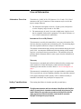
Mating Connectors
The attenuator has Type N connectors, one male and one female. These
connectors mate with all Type N connectors whose dimensions are
compatible with IEEE 287.
Type-N Male Connector
Type-N Female Connector
Center Conductor
Mating Plane
Center Conductor
Mating Plane
Outer Conductor
Mating Plane
0.207 inch (5.258 mm)
minimum
Figure 1
Outer Conductor
Mating Plane
0.207 inch (5.258 mm)
maximum
Type N Connectors
Keysight Technologies 8498A Operating and Service Manual 3
Installation
Installation
Initial Inspection
1. Inspect the shipping container for damage. If the shipping container or
cushioning material is damaged, it should be kept until the contents of
the shipment have been checked for completeness and the instrument
has been checked mechanically and electrically.
2. If the contents are incomplete, if there is mechanical damage or defect,
or if the instrument does not pass the electrical performance test, contact
the nearest Keysight Technologies Sales and Service office. Refer to
the Service and Support information in the front matter of this manual.
Keysight Technologies will arrange for repair or replacement of the
damaged or defective equipment. Keep the shipping materials for the
carrier’s inspection.
3. If you are returning the instrument for service, repackaging the
instrument requires original shipping containers and materials or their
equivalents. Keysight Technologies can provide packaging materials
identical to the original materials. Refer to Service and Support
information in the front matter of this manual for the Keysight
Technologies nearest you. Attach a tag indicating the type of service
required, return address, model number, and serial number. Mark the
container FRAGILE to insure careful handling. In any correspondence,
refer to the instrument by model number and serial number.
Preparation For Use
When you install the attenuator, make sure that the connectors do not
support weight or bear torque. Take care not to drop or mechanically
damaged the attenuator.
4 Keysight Technologies 8498A Operating and Service Manual
Operating Information
Operating Information
Principles of
Operation
The attenuation is achieved by a resistive film deposition on a beryllium
oxide substrate. The high power heat is dissipated by fins in the cooling cage
that surrounds the attenuator cartridge assembly.
WARNING
The high power attenuator card has a substrate of beryllium oxide. Beryllium
oxide in a powder form is a hazardous material and may be injurious to your
health if inhaled. Do not perform any operation on the beryllium oxide that
might generate dust. Defective attenuator cards should be returned to
Keysight Technologies for proper disposal.
Operator’s Check
The most accurate check of the attenuator is made using a network analyzer.
However, a simplified operator’s check of the attenuator can be made by
using either the substitution or insertion loss method.
Performance Tests
•
If a similar attenuator of known accuracy is available, a reference can be
established and then the unknown attenuator can be substituted in place
of the reference attenuator. If a known good attenuator is not available,
establish a reference on the measuring equipment, insert the device
under test, and check for the proper attenuated signal level.
•
Use an RF source in the proper frequency range and a detector with
readout device. Equipment should have sufficient accuracy to show that
the attenuator is working.
The best method for testing the attenuator is with an automatic network
analyzer or equivalent equipment of suitable accuracy. This method will
allow greater accuracy of measurement since system ambiguities can be
corrected. Simple quick-check techniques are mentioned under Operator’s
Check above. These techniques will provide a reasonable degree of
confidence that the attenuator meets its specifications.
Keysight Technologies 8498A Operating and Service Manual 5
Service
Service
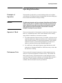
Repair
Repair of the attenuator is limited to the replacement of the attenuator
cartridge assembly (16) shown in Figure 2.
Refer to Figure 2 to identify the numbered items in the following procedure.
Attenuator Disassembly Procedure
1. Remove the 8 screws (10) that hold the two attenuator housings
(9) and (30) and remove the housings.
2. Remove the three screws (36) and lock washers (35) from both ends of
the attenuator assembly.
3. Remove the end fins (31) and (34), the RFI seals (11) and (19),
spacers (33), and the framed attenuator fins (32).
4. Remove the three cap screws (12) from both ends of the attenuator
assembly. It may be necessary to move the housing slightly to remove
the screws.
5. Slide the inner connector bodies (14) and (18) from the attenuator
cartridge assembly (16). Be careful not to let the sliding contacts (8) and
(29) and compression springs (7) and (28) slide from the contact holders
(6) and (27). Under normal conditions they will not slide out.
6. At this point the attenuator cartridge assembly (16) and the shim
washers are free from the overall assembly and can be returned to
Keysight Technologies. The attenuator cartridge assembly is the
housing for the attenuator card, the card half sections, and the shims.
Attenuator Reassembly Procedure
1. Place the framed attenuator fins (32), “D” ring spacers (33), and end fins
(31) and (34) on the attenuator cartridge assembly (16).
2. Position the RFI seals (11) and (19) and install end fins (31) and (34)
with screws (36) and lock washers (35).
3. Install the connector assemblies with the six screws (12). Use the end of
a toothpick to apply two small drops of Loctite 262 for each screw to the
threads in the attenuator body (16). Tighten the screws evenly to a torque
specification of 0.90 Nm (8 in-lbs).
CAUTION
Overtightening screws (12) beyond the specified torque may distort the card
clamp half sections and fracture the attenuator card.
6 Keysight Technologies 8498A Operating and Service Manual
Service
WARNING
Under no circumstances is the attenuator card to be machined, ground or
scraped. Beryllium oxide in a powder form is a hazardous material may be
injurious to your health if inhaled. Defective attenuator cards should be
returned to Keysight Technologies for proper disposal.
4. Install the eight screws (10) that hold the two housings (9) and (30).
Troubleshooting
To troubleshoot the attenuator perform the operator’s check. If the
instrument does not perform within limits, check the connectors. If the
connectors are not damaged, replace the attenuator cartridge assembly.
37
37
37
Figure 2
Attenuator Exploded View
Keysight Technologies 8498A Operating and Service Manual 7
Replacement Parts
Replacement Parts
To order a part listed in the replacement parts table, contact the nearest
Keysight Technologies office. Refer to “Service and Support” on page v.
Table 3
Replaceable Parts
Reference
Designation
Part Number
QTY
Description
1
08498-80001
1
Outer connector body Type N, female
2
1250-0915
1
Contact-RF connector series 7 mm-N; female
3
5040-0306
2
Insulator
4
08498-20014
2
Center conductor
5
08498-20019
2
Damper
6
08498-20016
2
Contact holder
7
1460-1618
2
Spring-CPRSN .054-IN-OD .258-IN-0A-LG
8
5020-3297
2
Contact, sliding
9
08498-40002
2
Attenuator housing
10
2200-0145
8
Screw-MACH 4-40 .438-IN-LG PAN-HD-POZI
11
08498-20024
2
RFI seal
12
3030-0070
1
Screw-SKT HD CAP 4-40 .625-IN-LG ALY STL
0470-1590
A/R
Loctite 262**
14
08498-20013
2
Inner connector body
15
08498-20018
2
Insulator
16
08498-60002
1
Attenuator cartridge assembly
17
08498-20018
Insulator
18
08498-20013
Inner connector body
19
08498-20024
RFI seal
20
1250-0918
1
Component-RF connector series 7 mm-N; SST
21
1250-0016
1
Component-RF connector series N; .75 IN
22
1250-0916
1
Body-RF connector series 7 mm-N straight
23
1250-0917
1
Contact-RF connector series 7 mm-N; male
24
5040-0306
Insulator
25
08498-20014
Center conductor
26
08498-20019
Damper
8 Keysight Technologies 8498A Operating and Service Manual
Replacement Parts
Table 3
Replaceable Parts (Continued)
Reference
Designation
Part Number
27
08498-20016
Contact holder
28
1460-1618
Spring-CPRSN .054-IN-OD .258-IN-0A-LG
29
5020-3297
Contact, sliding
30
08498-40002
Attenuator housing
31
08498-00002
2
End fin
32
08498-40001
6
Framed attenuator fin
33
08498-00005
1
D ring spacer*
34
08498-00002
35
2190-0014
1
Washer-LK INTL T NO. 2 .089-IN-ID
36
0520-0129
6
Screw-MACH 2-56 .312-IN-LG PAN-HD-POZI
37
08498-60006
1
Attenuator assembly
7120-7127**
1
Label, identification
QTY
Description
End fin
* NOTE: Some attenuators may have two spacers instead of one; 08498-00005 is the direct
replacement.
** Not shown
Table 4
Attenuator Cartridge Assembly Parts (Item 16 in Figure 2)
Part
Qty.
Part Number
30 dB, 25W attenuator card
1
1GT1-2674
Attenuator body
1
08498-20011
Card clamp half section
2
08498-20025
Washer
2
08498-20017
Lock
2
08498-20022
Tuning screw
2
08498-20023
Keysight Technologies 8498A Operating and Service Manual 9
This information is subject to change without notice.
© Keysight Technologies 1997, 1999, 2001, 2014
August 2014
*08498-90008*
08498-90008
www.keysight.com