1
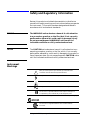
Agilent 8473B/C Crystal
Detector
Operating and Service
Manual
Agilent Part Number: 08473-90003
Printed in USA
Print Date: June 2001
Supersedes: May 1990
Notice
The information contained in this document is subject to change
without notice.
Agilent Technologies makes no warranty of any kind with regard
to this material, including, but not limited to, the implied
warranties of merchantability and fitness for a particular purpose.
Agilent Technologies shall not be liable for errors contained herein
or for incidental or consequential damages in connection with the
furnishing, performance, or use of this material.
Agilent Technologies assumes no responsibility for the use or
reliability of its software on equipment that is not furnished by
Agilent Technologies.
This document contains proprietary information which is
protected by copyright. All rights are reserved. No part of this
document may be photocopied, reproduced, or translated to
another language without prior written consent of Agilent
Technologies.
RESTRICTED RIGHTS LEGEND
Use, duplication, or disclosure by the U.S. Government is subject
to restrictions as set forth in subparagraph (c)(1)(ii) of the Rights
in Technical Data and Computer Software clause at DFARS
252.227-7013 for DOD agencies, and subparagraphs (c)(1) and
(c)(2) of the Commercial Computer Software Restricted Rights
clause at FAR 52.227-19 for other agencies.
Agilent Technologies, Inc.
1400 Fountaingrove Parkway
Santa Rosa, CA 95403-1799, U.S.A.
© Copyright 1990, 2001
Agilent Technologies, Inc.
ii Agilent 8473B/C Operating and Service Manual
In This Manual…
•
•
•
•
•
Overview, page 1
Specifications, page 2
Installation, page 4
Storage and Shipment, page 5
Operation, page 6
Operator’s Checks, page 8
•
Performance Tests, page 9
Adjustments, page 10
•
Service, page 11
“Replaceable Parts” on page 11
Agilent 8473B/C Operating and Service Manual iii
Warranty
Custom systems are warranted by contractual agreement between
Agilent Technologies and the customer.
Certification
Agilent Technologies, Inc., certifies that this product met its
published specifications at the time of shipment from the factory.
Agilent Technologies further certifies that its calibration
measurements are traceable to the United States National Institute
of Standards and Technology (NIST, formerly NBS), to the extent
allowed by the Institute’s calibration facility, and to the calibration
facilities of other International Standards Organization members.
Warranty
This Agilent Technologies system product is warranted against
defects in materials and workmanship for a period corresponding
to the individual warranty periods of its component products.
Instruments are warranted for a period of one year. During the
warranty period, Agilent Technologies will, at its option, either
repair or replace products that prove to be defective.
Warranty service for products installed by Agilent Technologies
and certain other products designated by Agilent Technologies will
be performed at Buyer’s facility at no charge within Agilent
Technologies service travel areas. Outside Agilent Technologies
service travel areas, warranty service will be performed at Buyer’s
facility only upon Agilent Technologies’ prior agreement and
Buyer shall pay Agilent Technologies’ round trip travel expenses.
In all other areas, products must be returned to a service facility
designated by Agilent Technologies.
For products returned to Agilent Technologies for warranty
service, Buyer shall prepay shipping charges to Agilent
Technologies and Agilent Technologies shall pay shipping charges
to return the product to Buyer. However, Buyer shall pay all
shipping charges, duties, and taxes for products returned to
Agilent Technologies from another country.
Agilent Technologies warrants that its software and firmware
designated by Agilent Technologies for use with an instrument
will execute its programming instructions when properly installed
on that instrument. Agilent Technologies does not warrant that
the operation of the instrument, or software, or firmware will be
uninterrupted or error free.
iv Agilent 8473B/C Operating and Service Manual
LIMITATION OF WARRANTY. The foregoing warranty shall
not apply to defects resulting from improper or inadequate
maintenance by Buyer, Buyer-supplied software or interfacing,
unauthorized modification or misuse, operation outside of the
environmental specifications for the product, or improper site
preparation or maintenance.
NO OTHER WARRANTY IS EXPRESSED OR IMPLIED.
AGILENT TECHNOLOGIES SPECIFICALLY DISCLAIMS THE
IMPLIED WARRANTIES OR MERCHANTABILITY AND
FITNESS FOR A PARTICULAR PURPOSE.
EXCLUSIVE REMEDIES. THE REMEDIES PROVIDED
HEREIN ARE BUYER’S SOLE AND EXCLUSIVE REMEDIES.
AGILENT TECHNOLOGIES SHALL NOT BE LIABLE FOR
ANY DIRECT, INDIRECT, SPECIAL, INCIDENTAL, OR
CONSEQUENTIAL DAMAGES, WHETHER BASED ON
CONTRACT, TORT, OR ANY OTHER LEGAL THEORY.
YEAR 2000. Agilent Technologies warrants that each Agilent
Technologies hardware, software, and firmware product on Agilent
Technologies’ Corporate Price List (dated July 1, 1998 or later)
delivered under the product’s contract of sale will be able to
accurately process date data (including, but not limited to,
calculating, comparing, and sequencing) from, into, and between
the twentieth and twenty-first centuries, and the years 1999 and
2000, including leap year calculations, when used in accordance
with the product documentation provided that all other products
(that is, hardware, software, firmware) used in combination with
such Agilent Technologies product(s) properly exchange date data
with it. If the agreement requires that specific Agilent
Technologies products must perform as a system in accordance
with the foregoing warranty, then that warranty will apply to
those Agilent Technologies products as a system, and Customer
retains sole responsibility to ensure the year 2000 readiness of its
information technology and business environment. The duration
of this warranty extends through January 31, 2001.
The remedies available under this warranty will be defined in,
and subject to, the terms and limitations of the warranties
contained in the contract of sale. To the extent permitted by local
law, this warranty applies only to branded Agilent Technologies
products and not to products manufacture by others that may be
sold or distributed by Agilent Technologies. Nothing in this
warranty will be construed to limit any rights or remedies
provided elsewhere in the contract of sale with respect to matters
other than year 2000 compliance.
Agilent 8473B/C Operating and Service Manual v
Assistance
Product maintenance agreements and other customer assistance
agreements are available for Agilent Technologies products.
For assistance, call your local Agilent Technologies Sales and
Service Office (refer to “Service and Support” on page vii).
vi Agilent 8473B/C Operating and Service Manual
Service and Support
By internet, phone, or fax, get assistance with all your test and measurement
needs.
Online assistance: www.agilent.com/find/assist
United States
(tel) 1 800 452 4844
Latin America
(tel) (305) 269 7500
(fax) (305) 269 7599
Canada
(tel) 1 877 894 4414
(fax) (905) 282-6495
New Zealand
(tel) 0 800 738 378
(fax) (+64) 4 495 8950
Japan
(tel) (+81) 426 56 7832
(fax) (+81) 426 56 7840
Australia
(tel) 1 800 629 485
(fax) (+61) 3 9210 5947
Europe
(tel) (+31) 20 547 2323
(fax) (+31) 20 547 2390
Asia Call Center Numbers
Country
Phone Number
Fax Number
Singapore
1-800-375-8100
(65) 836-0252
Malaysia
1-800-828-848
1-800-801664
Philippines
(632) 8426802
1-800-16510170 (PLDT Subscriber
Only)
(632) 8426809
1-800-16510288 (PLDT
Subscriber Only)
Thailand
(088) 226-008 (outside Bangkok)
(662) 661-3999 (within Bangkok)
(66) 1-661-3714
Hong Kong
800-930-871
(852) 2506 9233
Taiwan
0800-047-866
(886) 2 25456723
People’s Republic of
China
800-810-0189 (preferred)
10800-650-0021
10800-650-0121
India
1-600-11-2929
000-800-650-1101
Agilent 8473B/C Operating and Service Manual vii
Safety and Regulatory Information
Review this product and related documentation to familiarize
yourself with safety markings and instructions before you operate
the instrument. This product has been designed and tested in
accordance with international standards.
WARNING
The WARNING notice denotes a hazard. It calls attention
to a procedure, practice, or the like, that, if not correctly
performed or adhered to, could result in personal injury.
Do not proceed beyond a WARNING notice until the
indicated conditions are fully understood and met.
CAUTION
The CAUTION notice denotes a hazard. It calls attention to an
operating procedure, practice, or the like, which, if not correctly
performed or adhered to, could result in damage to the product or
loss of important data. Do not proceed beyond a CAUTION notice
until the indicated conditions are fully understood and met.
Instrument
Markings
!
When you see this symbol on your instrument, you should refer to the
instrument’s instruction manual for important information.
This symbol indicates hazardous voltages.
The laser radiation symbol is marked on products that have a laser output.
This symbol indicates that the instrument requires alternating current (ac) input.
The CE mark is a registered trademark of the European Community. If it is
accompanied by a year, it indicates the year the design was proven.
The C-Tick mark is a registered trademark of the Australian Spectrum Agency.
The CSA mark is a registered trademark of the Canadian Standards
Association.
viii Agilent 8473B/C Operating and Service Manual
1SM1-A
This text indicates that the instrument is an Industrial Scientific and Medical
Group 1 Class A product (CISPER 11, Clause 4).
This symbol indicates that the power line switch is ON.
This symbol indicates that the power line switch is OFF or in STANDBY
position.
Safety Earth
Ground
Before Applying
Power
This is a Safety Class I product (provided with a protective
earthing terminal). An uninterruptible safety earth ground must
be provided from the main power source to the product input
wiring terminals, power cord, or supplied power cord set.
Whenever it is likely that the protection has been impaired, the
product must be made inoperative and secured against any
unintended operation.
Verify that the product is configured to match the available main
power source as described in the input power configuration
instructions in this manual. If this product is to be powered by
autotransformer, make sure the common terminal is connected to
the neutral (grounded) side of the ac power supply.
Agilent 8473B/C Operating and Service Manual ix
Overview
This manual contains operating instructions for the Agilent
Technologies 8473B and 8473C Crystal Detectors. Included in the
manual is the information required to install and test the crystal
detector.
Description
The Agilent 8473B and 8473C crystal detector is a 50W (nominal)
device designed for measurement use in coaxial systems. The
detector converts RF power levels applied to the 50W input
connector into proportional values of dc voltage. The RF input
connector is a male APC 3.5 type connector (SMA compatible). The
detector module uses a Low Barrier Schottky diode and thin film
matching circuit that yield high sensitivity and broadband
performance. The detector measures relative power up to 200mW
and has a BNC female connector for the output jack which allows
the detected output to be connected to a SWR meter. The output
voltage polarity is negative, unless Option 003 is selected. The
frequency range is 10 MHz to 18 GHz for the 8473B, and 10 MHz
to 26.5 GHz for the 8473C. Complete specifications for the crystal
detectors are available in Table 1.
Options
The crystal detector is available with the following options (see
Table 1 for further descriptions):
Option 001:
Matched pair of detectors.
Option 002:
Square law load.
Option 003:
Positive polarity output.
Agilent 8473B/C Operating and Service Manual 1
Specifications
Specifications
Instrument specifications are listed in Table 1. These
specifications are the performance standards, or limits against
which the instrument may be tested.
RF may leak through the output connector, especially below 1
GHz. It can be reduced, if objectionable, with a suitable low-pass
filter.
NOTE
Table 1
Specifications
8473B
8473C
Frequency range (GHz)
0.01 to 18
0.01 to 26.5
Frequency response1, 2, 3
±0.2 dB over any octave to 8 GHz
±0.2 dB over any octave to 8 GHz
0.01 to 12 .4 GHz: ±0.3 dB
0.01 to 12 .4 GHz: ±0.3 dB
0.01 to 18 GHz: ±0.6 dB
0.01 to 20 GHz: ±0.6 dB
20 to 26.5 GHz: ±1.5 dB
from a −3.3 dB linear slope.
Maximum Operating input power
200 mW, peak or average
200 mW, peak or average
Maximum short term input power
1 watt (typical) peak or average for <1 minute
1 watt (typical) peak or average for <1 minute
>0.5 mV/ µW
0.01 to 18 GHz: >0.5 mV/ µW
Sensitivity
1, 4
Low level <−20 dBm
18 to 26.5 GHz: >0.18 mV/ µW
High level
<0.35 mW produces 100 mV output
<−0.35 mW produces 100 mV output up to 18 GHz
SWR1, 2
0.01 to 4 GHz: 1.2
0.01 to 4 GHz: 1.2
4 GHz to 18 GHz: 1.5
4 to 18 GHz: 1.5
18 to 26.5 GHz: 2.2
Input impedance
Output impedance2
50Ω (nominal)
50Ω (nominal)
1 to 2 KΩ (typically 1.3 KΩ)
1 to 2 KΩ (typically 1.3 KΩ)
shunted by 20 to 60 pF (typically 30 pF)
shunted by 20 to 60 pF (typically 30 pF)
Output polarity
Negative (refer to options for positive polarity units)
Negative (refer to options for positive polarity units)
Detector element
Supplied (refer to Table 2 on page 12 for
replacement modules)
Supplied (refer to Table 2 on page 12 for
replacement modules)
Bias
Not required
Not required
Noise
<50 µV p-p with CW applied to produce 100 mV
output, 400 kHz bandwidth
<50 µV p-p with CW applied to produce 100 mV
output, 400 kHz bandwidt
2 Agilent 8473B/C Operating and Service Manual
Specifications
Table 1
Specifications
8473B
8473C
001
Matched detector pair
Matched detector pair
Frequency response
characteristics (exclusive of basic
sensitivity) track within values listed
to the right.
0.01 to 12.4 GHz: ±0.2 dB
0.01 to 12.4 GHz: ±0.2 dB
0.01 to 18 GHz: ±0.3 dB
0.01 to 18 GHz: ±0.3 dB
002
Square law load
Square law load
Positive polarity output
Positive polarity output
Operating Temperature
−20° C to +85° C
−20° C to +85° C
Humidity
<95% relative
<95% relative
Vibration
20 G from 80 to 2,000 Hz
20 G from 80 to 2,000 Hz
Shock
100 G for 11 ms
100 G for 11 ms
Altitude
4,570 m (15, 000 ft.)
4,570 m (15, 000 ft.)
Weight
Net 14 g (0.5 oz)
Net 14 g (0.5 oz)
Dimensions
48 mm long, 10 mm diameter (1.9 in. long, 0.38 in.
diameter)
48 mm long, 10 mm diameter (1.9 in. long, 0.38 in.
diameter)
Options
0.01 to 26.5 GHz: ±0.5 dB
By choosing Option 002, the
deviation from ideal square law
response will be ±0.5 dB, although
the sensitivity specification is
decreased by a factor of 4.
003
Environmental
General
1. Specifications given for +25° C unless otherwise noted.
2. Measurement made at −20 dBm.
3. See Figure 1 on page 7.
4. Sensitivity decreases with increasing temperature, typically:
0.5 dB from −20° C to +25° C; 0.5 dB from +25° C to +40° C;
1 dB from +40° C to +55° C; 1.25 dB from +55° C to +75° C;
1 dB from +75° C to +85° C.
Agilent 8473B/C Operating and Service Manual 3
Installation
Installation
Initial Inspection
Inspect the shipping container for damage. If the shipping
container or cushioning material is damaged, it should be kept
until the contents of the shipment have been checked for
completeness and the instrument has been checked mechanically
and electrically.
The procedures for checking electrical performances are given
under “Performance Tests” on page 9. If the contents are
incomplete, if there is mechanical damage or defect, or if the
instrument does not pass the electrical performance test, notify
the nearest Agilent office (refer to “Service and Support” on
page vii). If the shipping container is damaged, or the cushioning
material shows signs of stress, notify the carrier as well as the
Agilent office. Keep the shipping materials for the carrier’s
inspection. At Agilent’s option, the office will arrange for repair or
replacement without waiting for claim settlement.
Mating
Connectors
The mating output connector used with the crystal detector must
be a male BNC connector. The mating RF input connector must be
a female APC 3.5 (SMA compatible) connector.
4 Agilent 8473B/C Operating and Service Manual
Storage and Shipment
Storage and Shipment
Environment
The instrument should be stored in a clean, dry environment. The
following environmental limitations apply to both storage and
shipment:
a. Temperature: -54× C to +85× C
b. Humidity: <95% relative
c. Altitude: <7,620 metres (25,000 feet)
d. Shock: 100 G for 11 ms
e. Vibration: 20 G from 80 to 2,000 Hz
Original
Packaging
Containers and materials identical to those used in factory
packaging are available through Agilent offices. If the instrument
is being returned to Agilent for servicing, attach a tag indicating
the type of service required, return address, model number, and
serial number. Also, mark the container FRAGILE to assure
careful handling. In any correspondence, refer to the instrument
by model number and serial number.
Agilent 8473B/C Operating and Service Manual 5
Operation
Operation
CAUTION
Static discharge can damage the detector module. A 100 pF
capacitor (1.2 m [4 ft.] of coax cable) charged to 14 volts stores 10-8
joules, the maximum pulse rating of the detector module. Connect
cables to test equipment and discharge the center conductor before
connecting to the detector.
CAUTION
DO NOT NEEDLESSLY HANDLE DETECTOR MODULE USED
IN CRYSTAL DETECTOR. Static electricity which builds up on a
person, especially on a cold dry day, must never be allowed to
discharge through the crystal detector. Avoid exposed leads to or
from the crystal detector, since these are often touched accidently.
Operating
Information
The crystal detector can be used as a demodulator to obtain a
pulse envelope which can then be observed on an oscilloscope. It
can also be used as a general purpose detector.
When using the detector with an oscilloscope, and the waveshapes
to be observed have rise times of less than 5 ms, the coaxial cable
connecting oscilloscope and detector should be as short as possible
and shunted with a resistor. Ideally, this resistor should be 50W to
terminate the coaxial cable properly. However, with 50W
resistance, the output video pulse may be too small to drive some
oscilloscopes. Therefore, the cable should be shunted with the
smallest value of resistance that will obtain suitable deflection on
the oscilloscope; typically the value will lie between 50W and 2
KW. The larger the resistance the more degration of rise time.
The power applied to the detector can be either modulated or
continuous wave (CW). If modulated at a 1,000 Hz rate, an SWR
meter can be used as an indicator. For CW detection, a dc
milliammeter or millivoltmeter can be used as the indicator.
6 Agilent 8473B/C Operating and Service Manual
Operation
Frequency
Response
The thin film input matching circuit was optimized for flat
frequency response, and low SWR which yields improved
performance in leveling loops and power monitoring applications.
Figure 1 shows the typical frequency response of the crystal
detector.
Figure 1
Typical Frequency Response of 8473B or 8473C Detector
Figure 2
Peak Power Measurement
Agilent 8473B/C Operating and Service Manual 7
Operation
Operator’s Checks
Peak Power
Measurement
The arrangement of equipment for peak power measurement is
shown in Figure 2. The procedure involves calibration of an
oscilloscope which, in turn, is used to calibrate a CW generator.
The output of the calibrated CW generator is measured with a
power meter; the peak power of a pulse is thereby measured. The
procedure is as follows:
1. Connect equipment as shown in Figure 2, step 1. Observe
pulse on a dc-coupled oscilloscope. Using a marking pencil,
mark on the graticule the base-to-peak amplitude of the pulse
envelope.
2. Replace the pulse source with a CW generator. While
observing the oscilloscope trace, adjust amplitude of CW
generator output to make detector output equal to that of the
pulse generator, as indicated by markings on graticule (step 1).
3. Leave CW generator at setting obtained in step 2. Disconnect
detector from CW generator. Connect output of CW generator
to power meter. Measure adjusted levels (set in step 2) of CW
generator output. The peak power of the pulse envelope
observed in step 1 is equal to the output power of the CW
generator.
8 Agilent 8473B/C Operating and Service Manual
Performance Tests
Performance Tests
The following paragraphs suggest methods to use for testing
detector specifications. For these tests refer to the manuals of the
equipment involved for operating instructions.
Frequency
Response Test
1. Using signal sources covering 10 MHz to 26.5 GHz with a 10
dB isolating attenuator and a power meter, connect power
sensor to attenuator. Adjust RF power level to -20 dBm input
to power sensor.
2. Without changing RF power level of signal source, disconnect
power sensor.
3. Connect detector to attenuator. Measure dc voltage output
from detector output from detector and record measurement.
4. Change frequency of signal source and repeat steps 1 through
3.
5. Since the detector follows a square-law response at this power
level, it’s output is proportional to power (PdB a 10 log Vo).
Total variation of detector readings should meet specifications
(see Table 1 on page 2) for all frequencies of interest across the
band.
NOTE
Multiple mismatch errors caused by attenuator SWR, power
sensor SWR, and detector SWR should be taken into account, as
well as the accuracy of the indicator used to measure the detector
output.
High Level
Sensitivity Test
1. Use a signal source at some convenient frequency between 10
MHz and 18 GHz and a dc voltmeter or oscilloscope as the
indicator. Connect the detector to signal source and adjust RF
power level for a 100 mV detected output from detector.
2. Disconnect detector from signal source and measure RF output
level. The RF output level should be £0.35 mW.
Agilent 8473B/C Operating and Service Manual 9
Performance Tests
Low Level
Sensitivity Test
1. Use a signal source covering 10 MHz to 18 GHz for the 8473B
or 10 MHz to 26.5 GHz for the 8473C, a 10 dB attenuator, and
a power meter. Connect attenuator to signal source and power
sensor to attenuator. Adjust RF power level for -20 dBm output
from attenuator. Verify the ambient temperature.
2. Disconnect power sensor from attenuator and connect detector.
Measure the dc voltage output from detector. The output
should be >5.0 mV up to 186 GHz for the 8473B/C and >1.8 mV
from 18 to 26.5 GHz for the 8473C at 25× C. Between 20× C
and 30× C with -20 dBm input power and a high impedance
video load the sensitivity slope is typically -0.04 dB/× C.
NOTE
Multiple mismatch errors caused by attenutator SWR, power
sensor SWR, and detector SWR should be taken into account, as
well as accuracy of the indicator used to measure detector output.
Match Test (SWR)
To verify the detector SWR specifications, use any system whose
measurement accuracies for SWR (residual SWR) are known.
Adjustments
The detector has no internal adjustments.
10 Agilent 8473B/C Operating and Service Manual
Service
Service
The succeeding paragraphs give instructions for repair of the
crystal detector. Additional maintenance information can be
obtained from the local Agilent office. Part numbers for
replaceable parts are given in Table 2 on page 12.
Replaceable Parts
To order a replaceable part, address order or inquiry to the
nearest Agilent office (refer to “Service and Support” on page vii).
Include the following information for each part: model number,
Agilent part number, and description.
Diode Module
Replacement
The diode module assembly includes the sealed diode and thin
film matching circuit. All other internal parts are to be retained
for re-use in the detector. The detector is operational after the
diode module has been replaced since replacement assemblies are
pre-tested.
CAUTION
The special diode module (see Figure 3 on page 13) contained in
the detector can be damaged in handling, removal, or installation
if certain precautions are not taken. The handling precautions
which follow should be read before performance of any operation
with the diode module when it is out of either the housing or the
module shipping container.
a. Before installing diode module into housing, touch exposed
metal on housing with your hand to discharge static
electricity. Then insert module into housing.
b. When handing diode to another person, touch hands first to
ensure there is no difference in static electricity potential
between you.
c. Ohmmeters should not be used to measure forward and
back resistance since it is easy to damage these diodes. The
difficulty arises because of the ohmmeter’s open-circuit
voltages and short currents.
Agilent 8473B/C Operating and Service Manual 11
Service
Replacing Diode
Module
The diode module can be damaged in handling or installation if
precautions are not taken. Before installing the diode module into
the connector housing, touch the exposed metal of the connector
housing with your hands to discharge static electricity.
CAUTION
Table 2
Replaceable Parts
Description
8473B and 8473C Assemblies
Part Number
1
BNC Connector Cap
1250-1514
Output Pin
08473-60001
RF Connector Housing
08473-60002
RF Washer (2)
33330-20006
Diode Module
Below
Replacement Diode Module Assemblies1
8473B
8473C
Single Diode Negative Polarity
08473-80001
08473-80004
Single Diode Positive Polarity (Option 003)
08473-80003
08473-80006
Matched Pair Diodes Negative Polarity (Option 001)
08473-80002
08473-80005
1. Refer to Table 1 on page 2 for description of options.
NOTE
Parts mentioned in the following procedure are identified in
Figure 3 on page 13.
1. Remove the RF connector housing from BNC connector cap
using 5/16 inch wrench and plastic jaw pliers. Protect crystal
detector body with heavy paper or tape.
2. Remove the diode module RF washer and output pin assembly.
CAUTION
Do not rotate module while inserting or removing; damage may
result.
CAUTION
When inserting diode module (large pin end) into center
conductor, exercise some restraint, do not force. The fingers of the
center conductor or the diode module might be damaged if the
module is not centered.
12 Agilent 8473B/C Operating and Service Manual
Service
3. Install the RF washer and diode module as shown in Figure 3.
Insert the larger diameter pin into the center conductor
contacts of the RF connector housing. Do not rotate the
module.
4. Place the other RF washer on the diode module as shown.
5. Install the output pin assembly on the diode module as shown.
6. Carefully place BNC connector cap over the diode module and
tighten firmly into place.
Do not exceed 0.8 NÞm (7 inch-lbs) torque.
CAUTION
Figure 3
Model 8473B or 8473C Crystal Detector Assembly
Agilent 8473B/C Operating and Service Manual 13