1
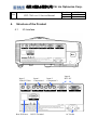
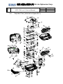
奇菱光電股份有限公司 Chi Lin Optronics Corp. Title CHT-726 Level 1 Service Manual Doc. No Version Page Service Manual For HD2+ DC3 DLP Front Projector Copyright©2004 Chilin Optronics Corp. All rights reserved. CS-72601 A3 1 / 75 奇菱光電股份有限公司 Chi Lin Optronics Corp. Title CHT-726 Level 1 Service Manual Doc. No Version Page CS-72601 A3 2 / 75 奇菱光電股份有限公司 Chi Lin Optronics Corp. Title CHT-726 Level 1 Service Manual Doc. No Version Page CS-72601 A3 3 / 75 Service Safety Notes Please read the Service Safety Notes before any service work is performed. Service work should be performed by qualified service technicians who are familiar with safety check and the DLP front projector, and take related service training before servicing. Warning 1. Place the projector on even surface during service work is performed. 2. Service work need to perform in an environment that is smoke and dust free. When used in areas where there is a lot of smoke or dust, the filter and lens should be cleaned before projector is returned to the user. 3. Disconnect power cord before servicing 4. The temperature of the lamp, ventilation slots and objects next to them may be extremely high during operation. Do not touch these areas before the temperature is sufficiently cool down. 5. Do not touch the internal structure of the lamp, any stain on the internal structure may cause unfixable damage on the lamp. 6. Do not stare into the beam of light or view directly. If stare into the beam of light is necessary for checking the lens, please wear sun-glasses. 奇菱光電股份有限公司 Chi Lin Optronics Corp. Title CHT-726 Level 1 Service Manual Doc. No Version Page CS-72601 A3 4 / 75 Contents 1. 2. 3. 4. Purpose.......................................................................................................................... 5 Definition of service level............................................................................................. 5 Specification.................................................................................................................. 5 Structure of the Product.............................................................................................. 6 4.1 I/O Interface ........................................................................................................... 6 4.2 Exploded View (attached as Appendix II) ............................................................. 7 4.3 Detail description of parts shown in 4.2 Product exploded View.......................... 8 4.4 Composition of Level 1 Modules (Parts) ............................................................... 9 5. Troubleshooting ......................................................................................................... 11 5.1 Troubleshooting Table ………………………………………………………….11 5.2 Block Diagram ………………………………………………………………….14 6. Service Mode............................................................................................................... 15 6.1 Options: ................................................................................................................ 15 6.2.1 Video Formatter ........................................................................................... 15 6.2.2 DLP Vsync ................................................................................................... 15 6.2 Test Patterns:........................................................................................................ 16 6.2.1 DLP Test Patterns ........................................................................................ 16 6.2.2 Lens Checkerboard....................................................................................... 21 6.2.3 4 X 4 Checkerboard ..................................................................................... 21 6.2.4 Scaler Test Patterns ...................................................................................... 22 6.3 Adjust CW............................................................................................................ 23 6.4 CW Index ............................................................................................................. 23 6.5 VGA Auto Calibration ......................................................................................... 24 6.6 MST 9888 Comp YPbPr ...................................................................................... 24 6.7 AD9882 VGA RGB ............................................................................................. 24 6.8 SAA 7118............................................................................................................. 25 6.9 DLP RGB Gain Offset ......................................................................................... 25 7. Firmware Updade ...................................................................................................... 26 8. Replacement Procedure (Disassembly & Assembly) .............................................. 28 8.1 Replace The Lamp module .................................................................................. 28 8.1.1 Resetting Lamp Timer.................................................................................. 29 8.2 Replace Cooling Fans .......................................................................................... 31 8.2.1 Replace The Front Axial Fan ....................................................................... 33 8.2.2 Replace The Rear Axial Fan ........................................................................ 36 8.2.3 Replace The Blower Fan.............................................................................. 39 8.3 Replace The Keypad ............................................................................................ 48 8.4 Replace The Control Board.................................................................................. 51 8.5 Replace The Connection Board ........................................................................... 54 8.6 Replace The Video Module, The I/O Board, The Ballast, The Thermal Sensor, and The Power Module ........................................................................................................ 57 8.7 Procedures for the video module adjustment ....................................................... 71 Appendix I : Spare Parts List for CHT 726.......................................................................... 75 奇菱光電股份有限公司 Chi Lin Optronics Corp. Title 1. CHT-726 Level 1 Service Manual Doc. No Version Page CS-72601 A3 5 / 75 Purpose The purpose of this manual is for the reference of authorized technician while proceeding level 1 service for the product mentioned in this manual. 2. Definition of service level Considering the service capability and the equipments of each service station may be different and the raising on service efficiency, service works have been concluded to 3 levels and defined by Customer Service Dept. (CS hereafter). The definition of “level 1 service” is defined based on service efficiency and effectiveness considerations. Level 1 service means modules replacement for projector. The concrete composition of level 1 modules (parts) will be mentioned in item 4.4 Composition of level 1 modules (parts). Level 1 service can be perform in a smoke and dust free environment and with limited equipments like computer and DVD Player. “Level 2 service” is defined as service on the PCBA. The technician who performs “level 2 service” should be knowledgeable on electricity system, except safety checks. Electronic equipment, such as AC/DC power source, oscilloscope, and other test equipments, are needed for performing level 2 service. “Level 3 service” is defined as service on the optical engine, but fans and lamp replacement. The service work on the optical engine should be performed in clear room. 3. Specification Please refer to CLO released HD2+ DC3 DLP Front Projector Approval Sheet. 奇菱光電股份有限公司 Chi Lin Optronics Corp. Title 4. CHT-726 Level 1 Service Manual Doc. No Version Page CS-72601 A3 6 / 75 Structure of the Product 4.1 I/O Interface Input 3 Video/S-Video Input 1 Component 1 Input 2 Component 2 Input 4 DVI/ PC + Rear IR Sensor RS232 Terminal AC Socket 奇菱光電股份有限公司 Chi Lin Optronics Corp. Title Doc. No Version Page CHT-726 Level 1 Service Manual 4.2 CS-72601 A3 7 / 75 Exploded View (attached as Appendix II) 18 1-1 19 2 1-9 31 5 2 24 14 32 2 21 28 4 27 25 3-1 26 3-2 2 6-4 4 4 3 6-1 6-8 31 8 2-6 6-5 29 4 34 4 28 1 38 4 37 2 1 6-9 36 2 1 35 1 13 6-7 6-3 7 4 12 6-6 32 1 5-5 1 29 2 15 6-2 32 1 4-4 2 5-4 20 4 5-1 29 2 11 2-8 4-5 9 4 33 2 2 22 40 2 30 2 39 2 10 2 2-4 2-1 2 6 2-5 2 8 2 2-3 2 16 2-2 2 2 2-7 2 奇菱光電股份有限公司 Chi Lin Optronics Corp. Title CHT-726 Level 1 Service Manual 4.3 Doc. No Version Page CS-72601 A3 8 / 75 Detail description of parts shown in 4.2 Product exploded View ITEM PART NAME QTY ITEM PART NAME QTY 1 P07260 TOP COVER SET(SILVER) 1 30-12 SCREW PH M3-0.5*5 C2 3 2 P05760 BOTTOM COVER(SILVER) 1 30-13 SCREW PH+EXW M4-0.7*6 C2 1 3 P05760 LAMP DOOR(SILVER) 1 30-14 SCREW PH M3-0.5*5 C2 13 4 P05760 FRONT LEG BUTTON 2 30-15 WIRE POWER-BALLAST 3P 150MM 1 5 P05760 FRONT LEG 2 30-16 WIRE FORMAT-BALLAST 5P 280MM 1 6 P05760 FRONT LEG COVER 2 31 PCBA P05760 CONTROL BOARD 1 7 P05760 FRONT LEG TOP HOUSING 2 32 PCBA P05760 KEYPAD BOARD 1 8 P05760 8025 FAN LOWER DUCT 1 33 PCBA P05760 VIDEO BOARD 1 9 P05760 8025 FAN UPPER DUCT 1 34 PCBA P05760 CONNECTION BOARD 1 10 P05760 8025 LAMP FAN RUBBER 4 35 WIRE POWER-CONTROL 6P 220MM 1 11 P05760 REAR RUBBER FOOT 1 36 WIRE POWER-VIDEOFORMAT 20P 120 1 12 P05760 FRONT LEG RUBBER 2 37 WIRE POWER-LAMPSWITCH 4P 90MM 1 13 P05760 KEYPAD PCB MYLAR 1 38 WIRE VIDEO-I/O 10P 60MM 1 14 P07260 RING CAP MYLAR RIGHT 1 39 WIRE VIDEO-CONTROL 12P 250MM 1 15 P07260 RING CAP MYLAR LEFT 1 40 WIRE CONTROL-KEYPAD 6P 430MM 1 16 FAN 12V DC 0.09A D80 AXIAL 1 41 WIRE VIDEO-KEYPAD 14P 240MM 1 17 FAN 12V DC 0.09A D80 AXIAL 1 42 WIRE SENSOR(P)-CONTROL 2P 240 1 18 P05760 VIDEO UPPER SHIELDING 1 43 WIRE POWER-THERMOSTAT 2P 220MM 1 19 P05760 BOTTOM NET 1 44 WASHER D2.5 E-RING STEEL 2 20 P05760 BOTTOM NET COVER 1 45 SCREW PH M3-0.5*5 C2 9 21 P05760 VIDEO SIDE NET 1 46 SCREW PH D3*8 C2 15 22 P05760 PCB FAN METAL DUCT 1 47 SCREW PH D3*5 C2 4 23 P05760 PCB FAN DUCT SHIELDING 1 48 SCREW BH M3-0.5*8 C2 13 24 P05760 LAMPDOOR FRONT LOCK 1 49 SCREW WH8 D3*6 C2 5 25 P05760 LAMPDOOR SIDE LOCK 1 50 SCREW WH8 M3-0.5*4 C2 10 26 P05760 FRONT LEG SLIDING 2 51 SCREW FH M3-0.5*10 C2 2 27 P05760 SAFETY LABEL 1 52 SCREW FHM3*8TP-P 4 28 P05760 I/O DECORATION LABEL 1 53 SCREW BH M4-0.7*9 C2 (E-RING) 2 29 P07260 OPTICAL ENGINE 1 54 SCREW HH UNC#4-40*8 H5 4 30 P05760 POWER MODULE 1 55 SCREW HH UNC4#-40*7 H5 2 30-1 P05760 POWER LOWER SHIELDING 1 56 P05760 FRONT LEG SPRING 2 30-2 P05760 POWER UPPER SHIELDING 1 57 P05760 CABLE CLAMP 1 30-3 P05760 BALLAST SHIELDING 1 58 AL TINESL 100*37 (2-D6) 1 30-4 P05760 I/O PCB SHIELDING 1 59 P05760 EMI GASKET 1 30-5 P05760 POWER LOWER MYLAR 1 60 TEMPERATURE LABEL 1 30-6 P05760 POWER UPPER MYLAR 1 61 P05760 DLP LOGO LABEL 1 30-7 P05760 BALLAST LOWER MYLAR 1 62 P07200 LOGO LABEL METAVISION 1 30-8 P05760 BALLAST 250W AC380V 1 63 P05760 TOP COVER SPONGE 2 30-9 PCBA P05760 IO BOARD 1 64 P05760 CONNECTION PRESSING 1 30-10 PCBA P05760 SENSOR BOARD 1 65 P05760 COVER LENSSHIFT SPONGE 1 30-11 PCBA P05760 POWER BOARD 1 奇菱光電股份有限公司 Chi Lin Optronics Corp. Title 4.4 CHT-726 Level 1 Service Manual Doc. No Version Page CS-72601 A3 9 / 75 Composition of Level 1 Modules (Parts) Level 1 service means to replace all mechanical parts (cover, base, screw and label so on),electronic modules (also include the cable which connects two modules) listed below on this page and next page. In order to help technician understand the figure and composition of each module and mechanical part, drawing of modules and parts are as drawing listed on this page and next page. Others (ex. Cable, Screw, Packing material, Accessories, etc.) are not included in following drawings. The items of level 1 service will be updated base on ASP (After Service Provider) capability and efficiency/effectiveness consideration. Mechanical Parts: Upper Cabinet Lamp Door Blower Fan Rear Axial Fan Front Axial Fan Bottom Cabinet 奇菱光電股份有限公司 Chi Lin Optronics Corp. Title CHT-726 Level 1 Service Manual Doc. No Version Page Electronic Parts: Keypad Lamp Video Module Control Board Ballast Connection Board IO Board Thermal Sensor Power Module CS-72601 A3 10 / 75 奇菱光電股份有限公司 Chi Lin Optronics Corp. Title 5. CHT-726 Level 1 Service Manual Doc. No Version Page CS-72601 A3 11 / 75 Troubleshooting You use the Troubleshooting section to diagnose problems with projector. You can refer to a variety of symptoms for troubleshooting. Each symptom leads you trough a series of steps that will ultimately result in a solution. The solutions begin with the most simple and progress to the most complex. In addition to the Troubleshooting Table, you can also check internal voltages and signals to diagnose a defective part by Block Diagram. 5.1 Troubleshooting Table Symptoms Possible Cause Blue LED doesn’t light up The cable from the keypad to control board does not connect well. The cable from control board to power module doesn’t connect well The keypad malfunction The control board defective The power module malfunction Countermeasures Check the connection of the cables If the projector illuminates after pressing the power key, please replace the keypad. Replace the control board. Replace the failed power module Remote controller failure Batteries are dead Remote controller malfunction IR sensor is malfunction Replace the batteries Replace the remote controller If the remote works fine, then test the front and rear IR sensors, if the front IR sensor fails, replace the control board. If the rear IR sensor malfunctions, replace the RS232 board. The blue LED and the over temperature indicator flash alternately The cable for the front/rear thermal sensor doesn’t connect well. The front/rear thermal sensors malfunctions The wire for fan doesn’t connect well The rear Axial Fan failure The front Axial Fan failure The blower fan failure The control board fails Wrong firmware for the control board. Reconnect the cable to connector. Replace the abnormal front/rear thermal sensor The wire from the power module to the formatter board does not connect well The 4 Pin FFC doesn’t well connect the color wheel and the Check the wire Check the connector pins on connect board. Remove the connect board from the video module and disconnect the wire The sequence is two blue LED blink followed by one red indicator blink All three fans do not rotate. Color wheel does not spin after the projector power on Reconnect the wire to connector Replace the malfunction fan (front/rear/blower fan). Replace the control board. Please contact CLO for the firmware update on the control board. 奇菱光電股份有限公司 Chi Lin Optronics Corp. Title CHT-726 Level 1 Service Manual Doc. No Version Page CS-72601 A3 12 / 75 formatter board The connect board deficient The video module malfunctions The formatter board fails. from the power module to Video module, power on projector, if the color wheel spin normally, it means the formatter board functions well, but the video module malfunctions. Otherwise, the formatter board fails, please contact CLO for level 3 service. The lamp doesn’t light up after the projector powers on, but the color wheel and fans spin normally Lamp failure The 5-pin wire which connects from ballast to the formatter board doesn’t connect well The black wire from Ballast to lamp doesn’t connect well or is failed The white switch from the power module to the lamp housing doesn’t well connect. The connect board malfunctions or doesn’t connect the formatter board and the video module well The Ballast malfunctions The rotation rate of the color wheel isn’t correct. Replace the lamp Reconnect the wires or replace the failed wires Reconnect the connect board. If it is failed, replace it. Replace the ballast The failure on photo sensor will cause the spin rate of color wheel isn’t correct, please contact CLO for the level 3 service for repairing photo sensor. The keypad malfunction Keypad is defective if one or two buttons no function The wire from the video module to the keypad doesn’t well connect. The video module malfunctions if all buttons no function Replace the keypad if one or two buttons no function Reconnect the wire Replace the video module if all buttons no function. Projector turns off automatically in minutes after power on. The control board malfunctions Replace the failed control board. Screen flickering The lamp failure The Ballast failure Replace failed lamp Replace the ballast with a good one. Screen jagged The de-interlace malfunctions Replace the video module Incorrect image’s color Incorrect color wheel index Wrong firmware for the formatter board “Power Off” message keeps showing up automatically. The control board fails Feed in Red 256 gray bar pattern and adjust the color wheel index Reload firmware. Please contact CLO for the detail. Replace the control board 奇菱光電股份有限公司 Chi Lin Optronics Corp. Title CHT-726 Level 1 Service Manual Doc. No Version Page CS-72601 A3 13 / 75 White verticals on the image The connect board malfunction DMD malfunctions Replace connect board Contact CLO for level 3 service Incorrect image The connect board does not connect well The video module is defective. The connector on the video module fails Wrong firmware on the formatter board DMD failure Reconnect the connect board Replace the connect board. Replace the video module Reload correct firmware to formatter board. Please contact CLO for the detail Contact CLO for level 3 service 1/16 of image area is shown as a horizontal stripe The formatter board malfunction Contact CLO for level 3 service. Update firmware failure The cable between the Video module and the power module doesn’t well connect or fail The cable from the video module doesn’t connect to the RS232 board The RS232 input fails The video module failure Check the connection between the video module and the power module. If it is failed, replace it. Check the cable which connects the video module and the RS232 board. Replace the RS232 board Replace the video module. 奇菱光電股份有限公司 Chi Lin Optronics Corp. Title CHT-726 Level 1 Service Manual 5.2 Block Diagram Doc. No Version Page CS-72601 A3 14 / 75 奇菱光電股份有限公司 Chi Lin Optronics Corp. Title 6. CHT-726 Level 1 Service Manual Doc. No Version Page CS-72601 A3 15 / 75 Service Mode The Service Mode is released for authorized distributor and technician only. It provides Test Patterns, Adjust CW, CW Index, VGA Auto Calibration, MST9888 Component YPbPr, AD9882 VGA RGB, SAA7118, DLP RGB Gain Offset, and firmware version information for the Video board, the formatter board, and the control board. Authorized technician will need to enter service mode when doing inspection and color setting adjustment after replacing the video module. How to enter Service Mode By pressing clockwise Service Mode. and “MENU” button to enter into the main menu of the How to exit Service Mode Press the “ exit” button to leave Service Mode 6.1 Options: There are two items under Option, one is video format, which is set to “Auto” generally, and another is DLP Vsync. 6.2.1 Video Format Video Format provides 20 different formats, such as NTSC 60Hz, PAL 50/ 60Hz…etc. for use. Normally, the default of video format is “Auto”, so that projector to take all video formats. However, distributor would force projector to take one video format if needed. ※ Caution: Once the Video Format is selected to particular format, projector will not read signal of other format. 6.2.2 DLP Vsync DLP Vsync shows the signal is 50Hz or 60Hz. 奇菱光電股份有限公司 Chi Lin Optronics Corp. Title CHT-726 Level 1 Service Manual 6.2 Doc. No Version Page CS-72601 A3 16 / 75 Test Patterns: Test Patterns provides several patterns for checking the DMD chip, back focal length, ANSI contrast, and scaler. 6.2.1 DLP Test Patterns DLP Test Patterns contains 10 test patterns in order to check blemish, dark pixel, bright pixel, unstable pixel, adjacent pixels, and border defects. Blue test screen This pattern is used to test for Major Dark Blemishes and Dark Pixels. All areas of the screen are colored at a specific blue level, based on a standard 0-255 RGB scale: Major Dark Blemish Test Blue Value Red Value Green Value 90 0 0 Gray 30 test screen This pattern is used to test light border blemishes and bright pixels. All areas of the active area are colored at a specific gray level, based on MS Paint 0-255 RGB scale: Border Defect Test Blue Value Red Value Green Value 30 30 30 Gray 10 test screen This pattern is used to test Major Light Blemishes and Light Pixels. The full screen area is colored at a 奇菱光電股份有限公司 Chi Lin Optronics Corp. Title CHT-726 Level 1 Service Manual Doc. No Version Page CS-72601 A3 17 / 75 specific gray level, based on a standard 0-255 RGB scale: Major Light Blemish Test Blue Value Red Value Green Value 10 10 10 White test screen This pattern is used to test Minor Dark Blemishes. The full screen area is colored specifically, based on a standard 0-255 RGB scale: Minor Dark Blemish Test Blue Value Red Value Green Value 255 255 255 Black test screen This pattern is used to test Minor Light Blemishes. The full screen area is colored specifically, based on a standard 0-255 RGB scale: Minor Light Blemish Test Blue Value Red Value Green Value 0 0 0 Red ramp test screen This pattern is used to test for unstable pixels. The full screen area is colored at an increasing red level on a standard 0-255 RGB scale, beginning at 0 (black), and ending at 255 (full red): Unstable Pixel Test Blue Value Red Value Green Value 0 Start 0, end 255 0 奇菱光電股份有限公司 Chi Lin Optronics Corp. Title CHT-726 Level 1 Service Manual Doc. No Version Page CS-72601 A3 18 / 75 H/V Grid test screen This pattern is used to test projection lens performance. It is CLO internal checking pattern for production. It is nothing to go with DMD Checking. H/V Grid test screen Blue Value N/A Red Value Green Value N/A N/A Red gray scale test screen This pattern is used to test projection lens performance. It is CLO internal checking pattern for production. It is nothing to go with DMD Checking. Red gray scale test screen Blue Value Red Value Green Value 0 Start R0-G0-B0, End R255-G0-B0 0 Green gray scale test screen This pattern is used to test projection lens performance. It is CLO internal checking pattern for production. It is nothing to go with DMD Checking. Green gray scale test screen Blue Value Red Value Green Value 0 0 Start R0-G0-B0, End R0-G255-B0 Blue gray scale test screen This pattern is used to test projection lens performance. It is CLO internal checking pattern for production. It is nothing to go with DMD Checking. 奇菱光電股份有限公司 Chi Lin Optronics Corp. Title CHT-726 Level 1 Service Manual Doc. No Version Page CS-72601 A3 19 / 75 Blue gray scale test screen Blue Value Red Value Green Value Start R0-G0-B0, End R0-G0-B255 0 0 ACCEPTANCE REQUIREMENTS 1. Conditions of Acceptance All DMD image quality returns will be evaluated using the following projected image test conditions: a. Texas Instruments performs image quality acceptance testing on specifically designed HD2 DMD test equipment. If the DMD is judged to complete this test successfully, it is acceptable. b. Texas Instruments understands the customer will perform image quality testing in their own PTV application. Incoming test conditions must be mutually agreed to between customer and Texas Instruments before initial DMD acceptance testing begins. c. Texas Instruments recommends cleaning the DMD before installation to the projector, according to the instructions in the DMD Cleaning Document (TI drawing #2504640). d. Texas Instruments recommends handling the DMD according to the instructions in the DMD Handling Document (TI drawing #2504641) e. Projector de-gamma correction Curve shall be in accordance with Test Screen definitions on sheets 3 & 4 of this document. The correct RGB value must align with the appropriate De-Gamma Curve. Reference Note # 1: If the De-Gamma curve is not known then the Linear Lux values for a given test screen can be calculated by the following equations The following are center point Lux measurements for a gray screen calculation. SLR (Spoke Light Recapture) is a contributor to the white Lux value. For absolute accuracy it must be turned off when making the White Lux measurement. ( White Lux value – Black Lux value) --------------------------------------------------- = Lux per Step 255 Therefore, the Lux Value of a Gray 10 = 10 x Calculated Lux per Step Reference Note # 2: Peak Lux Percent is calculed by determining what precent of 255 is a test screen. Example: Gray 10 is 10 / 255 or 3.9% of the white test screen’s Lux value. f. The diagonal size of the projected image shall be at minimum 52inches (132cm). g. The projected image shall be inspected from a 60 inch (152cm) minimum viewing distance. h. Projector must be properly focused on the DMD array as shown on the screen. i. Testing time is limited to 20 seconds per screen. 奇菱光電股份有限公司 Chi Lin Optronics Corp. Title CHT-726 Level 1 Service Manual Doc. No Version Page CS-72601 A3 20 / 75 j. White Peaking mode (SLR, spoke light recapture) must be turned off. k. Refer to Table 1 for acceptance criteria, in the specified order: 2. Test Sequence: Tests shall be run in the sequence listed in Table 1. TEST ORDER CHECK ITEMS SCREEN ACCEPTANCE CRITERIA 1 Major Dark Blemish Blue 90 Zero Dark blemishes 2 Dark Pixel Blue 90 Zoned Screen (See below Figure 1) Zero Dark pixels allowed in Zone A ≤ 2 dark pixels allowed in Zone B Zero Adjacent dark pixels 3 Border Defects Gray 30 4 5 6 Major Light Blemish Light Pixel Minor Blemishes Gray 10 Gray 10 White or Black 7 Unstable Pixel Red Ramp Screen Zero Border Defects Zero Non-Active Area Artifacts Zero Light blemishes Zero Light pixel Total of Dark and Light Blemishes ≤ 6 (see note 4 for size limitation) Zero Unstable pixels Table 1. Image Quality Specification Test Criteria ※Notes: 1. This specification applies to the active pixel area (addressed pixels) of the DMD only. All other defects outside of this area are acceptable. Also in this manner, customer projection optics must control light effectively. Light reflecting from anywhere outside of the active pixel area is not a basis for DMD acceptance. 2. All cosmetic DMD defects (scratches on the external DMD surface, for example) will be judged using the above test conditions on the projected image only. 3. Projected blemish numbers include the shadow of the artifact in addition to the artifact itself. (Count = 2). 4. The projected image shall not contain any blemish more than 4 inches long, measured on a 42 inch (107cm) diagonal screen. 5. Any defect not mentioned in the above criteria shall be acceptable, unless customer and Texas Instruments mutually agree that it is a problem for the marketplace. 奇菱光電股份有限公司 Chi Lin Optronics Corp. Title CHT-726 Level 1 Service Manual Doc. No Version Page CS-72601 A3 21 / 75 6.2.2 Lens Checkerboard Lens Checkerboard pattern is for checking the back focal length. In normal situation, the every black pixel in white square or white pixel in black square should be clear; otherwise projector should be returned to CLO for adjustment. When you enter Lens Checkerboard, you would see the below pattern. 6.2.3 4 X 4 Checkerboard 4 X 4 Checkerboard is for measuring ANSI Contrast. The pattern is as below: 奇菱光電股份有限公司 Chi Lin Optronics Corp. Title CHT-726 Level 1 Service Manual Doc. No Version Page CS-72601 A3 22 / 75 6.2.4 Scaler Test Patterns Scaler test patterns provide gray, red, green, and blue patterns for technician to check the color level setting. Normally, it must be set to “NONE”, or projector would only project pattern out even you feed in signals. Solid Color When Scaler test pattern is set to “Solid Color”, it is allowed to enter or exit “All”, “R”, “B”, and “G” patterns of Color components by pressing “up” and “down” buttons and pressing “Right” and “Left” buttons to adjust the each color’s level on “Solid Field Level.” Note: Any adjustment affects the pattern only, and no effect on the performance of projector. 奇菱光電股份有限公司 Chi Lin Optronics Corp. Title CHT-726 Level 1 Service Manual Doc. No Version Page CS-72601 A3 23 / 75 Vertical Bars When test patterns is set to “Vertical Bars”, projector displays 64 step bar in gray, red, green and blue for people to check if the color level clear and no any color blooming. 6.3 Adjust CW When Adjust CW is “On”, repair people could adjust the CW index setting on Color Wheel; when it is “Off”, no adjustment can be done. Normally it is set to “Off”. 6.4 CW Index CW Index is for setting the color coordination. This function mainly use in factory. We suggest do not change any setting on this section. However, if the video module replacement is necessary, please remember the CW Index no of the color coordination setting and load the no before the video module adjustment. 奇菱光電股份有限公司 Chi Lin Optronics Corp. Title 6.5 CHT-726 Level 1 Service Manual Doc. No Version Page CS-72601 A3 24 / 75 VGA Auto Calibration VGA Auto Calibration is a function for technician to perform ADC calibration on the video board. Please refer to chapter 8.7 “ Procedure of the video module adjustment” for more information. 6.6 MST 9888 Comp YPbPr A function for people adjusts the parameter on Gain and Offset of YPbPr on MST 9888 chip when the video Board is replaced. To perform this function, please refer to chapter 8.7 “Procedure of the video module adjustment” for more information on adjustment on YPbPr parameter. Note: MST 9888 Comp YPbPr is hided when the input signal is VGA or RGB signal. 6.7 AD9882 VGA RGB AD 9882 VGA RGB function is for adjusting the parameter setting on VGA when Video Board is replaced. Please refer to chapter 8.7 “Procedure of the video module adjustment” to know more on this function. Note: AD 9882 VGA RGB is hided when you input YPbPr signal. 奇菱光電股份有限公司 Chi Lin Optronics Corp. Title 6.8 CHT-726 Level 1 Service Manual Doc. No Version Page CS-72601 A3 25 / 75 SAA 7118 SAA 7118 is a function to adjust the brightness, contrast, saturation and tint on S-Video, Composite, and Component input. 6.9 DLP RGB Gain Offset DLP RGB Gain Offset is allowed people to adjust the optimal gain and offset setting. 奇菱光電股份有限公司 Chi Lin Optronics Corp. Title 7. CHT-726 Level 1 Service Manual Doc. No Version Page CS-72601 A3 26 / 75 Firmware Updade Firmware update is made for the need to improve performance and functionality. If you are experiencing stability, reliability or image quality issues on your CLO projectors, the firmware update might be an option of the solutions. Due to the hardware version may vary among versions and models, each firmware update only provides solutions to specific issues in specific version & models of machine. Applying inappropriate firmware might cause malfunction on your projectors. Please, check the documentations or needed information (such as hardware version, firmware version or serial number) associate with firmware before applying firmware on your projector. To update firmware for NHT 726 front projector, you need a RS-232 cable and Flash Upgrader.exe on Projector Service AID CD that only provide to authorized technician and distributor. Procedure to Update Firmware on Video Module Step 1. Plug RS232 cable into computer and projector. Step 2. Double click at “ FlashUpgarder” to open this file. Step 3. Click “Choose” and select “FlashAll.inf”. There are five .HEX files in FlashAll.inf, flasher.hex, bootcode.hex, gui.hex, configdata.hex, and romcode.hex. Technician is supposed to download all of them. 奇菱光電股份有限公司 Chi Lin Optronics Corp. Title CHT-726 Level 1 Service Manual Doc. No Version Page Step 4. Check COM Port (RS232) and set the “Baud Rate” to 115200. Step 5. Click “Flash” bottom to load firmware to Video Board. Step 6. Power on projector. Step 7. Download .HEX file: Flasher, Bootcode, gui, configdata, romcode. Note: Do not click “Cancel” button when firmware is loading. Step 8. Click “Close” button when firmware is loaded. CS-72601 A3 27 / 75 奇菱光電股份有限公司 Chi Lin Optronics Corp. Title 8. CHT-726 Level 1 Service Manual Doc. No Version Page CS-72601 A3 28 / 75 Replacement Procedure (Disassembly & Assembly) 8.1 Replace The Lamp module The temperature of the lamp, ventilation slots and objects next to them may be extremely high during operation. Before replacing the lamp module, please wait till the temperature is sufficiently cool down. 1. 2. Loosen 2 screws from Lamp Door. Electric screw driver torque set for 11 lbs. 3. 4. Take off the lamp door from projector. Electric screw driver torque set for 11 lbs. 5. 6. Loosen 4 screws on lamp module. Electric screw driver torque set for 11 lbs. 奇菱光電股份有限公司 Chi Lin Optronics Corp. Title CHT-726 Level 1 Service Manual Doc. No Version Page CS-72601 A3 29 / 75 7. Pull out the failed lamp 8. The lamp module. Replace a good lamp module in and secure screws on. 9. Place lamp door on, press all clips of the lamp door into the top and the bottom cabinet and secure 2 screws. 10. Electric screw driver torque set for 11 lbs. 8.1.1 Resetting Lamp Timer Connect the power cord into AC socket of the projector and turn on the projector. Press “Menu” on Projector Control Panel or Remote Control. Select “Option” on OSD, then select “Lamp Timer Reset”, when enter to “Lamp Timer Reset”, select “Yes” to reset previous timing record. Information & Warning: To reset Lamp timer is only allowed when replacing the lamp. If you reset the lamp timer and continue to use the same lamp, this may cause the lamp damaged and exploded. 奇菱光電股份有限公司 Chi Lin Optronics Corp. Title CHT-726 Level 1 Service Manual Doc. No Version Page CS-72601 A3 30 / 75 奇菱光電股份有限公司 Chi Lin Optronics Corp. Title 8.2 CHT-726 Level 1 Service Manual Doc. No Version Page CS-72601 A3 31 / 75 Replace Cooling Fans 1. 2. Loosen 2 screws from the Lamp Door. Electric screw driver torque set for 11 lbs. 3. Take off the lamp door from the projector. 4. 5. Turn over the projector and loosen the screw by the I/O port. Electric screw driver torque set for 11 lbs. 6. 7. Loosen 8 screws from the bottom cabinet. Electric screw driver torque set for 11 lbs. 奇菱光電股份有限公司 Chi Lin Optronics Corp. Title CHT-726 Level 1 Service Manual 8. 9. Doc. No Version Page CS-72601 A3 32 / 75 Turn over the projector, take off the top cabinet, and disconnect the 10-pin cable which connects the video board and the keypad and the 6-pin cable connecting controller board and keypad. Electric screw driver torque set for 6.6 lbs. 10. Take off the top cabinet. ※ Hereinafter, you can find disassembly and reassembly procedure for each cooling fan. (1) The Front Axial Fan (2) The Rear Axial Fan (3) The Blower Fan 奇菱光電股份有限公司 Chi Lin Optronics Corp. Title CHT-726 Level 1 Service Manual Doc. No Version Page CS-72601 A3 33 / 75 8.2.1 Replace The Front Axial Fan 1. 2. Take step 1-7 from page 29 to 30 to dismantle the top cabinet. Electric screw driver torque set for 6.6 lbs. The Front Axial Fan 3. 4. 5. 6. 7. 8. Disconnect the 3-pin cables from the red connector on the control board. Electric screw driver torque set for 6.6 lbs. Loosen 2 screws on the lamp door front lock and take it off from the bottom cabinet. Electric screw driver torque set for 6.6 lbs. Loosen 2 screws to take off the axial fan module. Electric screw driver torque set for 6.6 lbs. 奇菱光電股份有限公司 Chi Lin Optronics Corp. Title CHT-726 Level 1 Service Manual Doc. No Version Page CS-72601 A3 34 / 75 9. Loosen 1 screw to disassemble the duct. 10. Electric screw driver torque set for 6.6 lbs. 11. Remove the 4 fan Rubbers from the failed fan. Replace the failed fan with a good one. 12. Place the fan rubber onto the fan and assemble the duct on. Note: The label on the fan must be toward to the lamp door when assembly. 13. Place the fan module back to the bottom cabinet, secure 2 screws on, and reconnect the fan’s cable to the control board. Secure the front lock back. 奇菱光電股份有限公司 Chi Lin Optronics Corp. Title CHT-726 Level 1 Service Manual Doc. No Version Page CS-72601 A3 35 / 75 14. Reconnect the cables which connect to keypad on top cabinet. And place the top cabinet on. Note: The two wires should be pull backward to the electronic parts. If the wires are left on the optical engine, the keypad sensitivity will be affected. 15. Electric screw driver torque set for 6.6 lbs. 16. Test the projector. If the unit functions well, go to step 11. If the LED flashs, disconnect the wires from keypad and go back to step 6 on page 30 and disassemble the projector to check the connectors and fans. 17. Turn over the projector and secure 9 screws on the bottom cabinet. 18. Electric screw driver torque set for 11 lbs. 19. Place lamp door on, press all clips of the lamp door into the top and the bottom cabinet and secure 2 screws. 20. Electric screw driver torque set for 11 lbs. 奇菱光電股份有限公司 Chi Lin Optronics Corp. Title CHT-726 Level 1 Service Manual Doc. No Version Page CS-72601 A3 36 / 75 8.2.2 Replace The Rear Axial Fan 1. Take step 1-7 from page 29 to 30 dismantle the top cabinet. 2. Remove the 3-pin cable from the clips. Disconnect the 3-pin fan cable from the green connector on the control board. Electric screw driver torque set for 6.6 lbs. The Rear Axial Fan 3. 4. 5. 6. 7. Loosen 2 screws which secure the rear axial fan module. Pull out the real axial fan module from the bottom cabinet. Electric screw driver torque set for 6.6 lbs. Loosen 2 screws to take off the metal duct from the rear axial fan. Electric screw driver torque set for 11 lbs. 奇菱光電股份有限公司 Chi Lin Optronics Corp. Title CHT-726 Level 1 Service Manual 8. Doc. No Version Page CS-72601 A3 37 / 75 Loosen 4 screws to pull up the rear axial fan from the duct shielding, and replace the failed rear Axial fan. Note: The wire should go thru the opening of the duct. 9. Electric screw driver torque set for 11 lbs. 10. Assemble the duct shielding and the duct back. 11. Electric screw driver torque set for 11 lbs. 12. Place the rear axial fan module back to the bottom cabinet and secure it. 13. Electric screw driver torque set for 6.6 lbs. 14. Reconnect the fan cable to the control board. 奇菱光電股份有限公司 Chi Lin Optronics Corp. Title CHT-726 Level 1 Service Manual Doc. No Version Page CS-72601 A3 38 / 75 15. Reconnect the cables which connect to keypad on top cabinet. And place the top cabinet on. Note: The two wires should be pull backward to the electronic parts. If the wires are left on the optical engine, the keypad sensitivity will be affected. 16. Electric screw driver torque set for 6.6 lbs. 17. Test the projector. Test the projector. If the unit functions well, go to step 11. If the LED flashs, disconnect the wires from keypad and go back to step 6 on page 30 and disassemble the projector to check the connectors and fans. 18. Turn over the projector and secure 9 screws on the bottom cabinet. 19. Electric screw driver torque set for 11 lbs. 20. Place the lamp door on and secure it. 21. Electric screw driver torque set for 11 lbs. 奇菱光電股份有限公司 Chi Lin Optronics Corp. Title CHT-726 Level 1 Service Manual Doc. No Version Page CS-72601 A3 39 / 75 8.2.3 Replace The Blower Fan 1. Take step 1-7 from page 29 to 30 to dismantle the top cabinet. 2. Loosen 2 screws securing the control board. Pulling up the control board and disconnecting the wire from the blue connector. Electric screw driver torque set for 6.6 lbs. 3. 4. Remove the lamp door front lock and the front axial fan from the bottom cabinet by loosening 4 screws (2 for lamp door front lock and 2 for Axial fan) 5. Loosen 2 screws on the connection board. Remove the EMI shielding and disconnect the connection board from the Video module. Note. Do not pull the connection board out from the connector on the formatter board, or unfixable damage on connection board may be occurred 6. Electric screw driver torque set for 11 lbs. 奇菱光電股份有限公司 Chi Lin Optronics Corp. Title CHT-726 Level 1 Service Manual 7. Doc. No Version Page CS-72601 A3 40 / 75 8. Loosen 1 screw from the lamp housing for unpluging the power cord connecting the lamp housing and the ballast. Electric screw driver torque set for 11 lbs. 9. Unplug the two ropes from the thermostat. 10. Disconnect the white switch connecting the lamp housing and the power module. 11. Disconnect the 5-pin cable of the lamp switch from the formatter board. 奇菱光電股份有限公司 Chi Lin Optronics Corp. Title CHT-726 Level 1 Service Manual Doc. No Version Page CS-72601 A3 41 / 75 12. Loosen 1 screw from the shielding net. And take off the shielding net. 13. Disconnect the cable from the formatter board. 14. Remove the tapes which tape the 10-pin cable which connects the video board and the keypad and the 6-pin cable connecting the control board and the keypad. 15. Loosen 5 screws to take the optical engine from the bottom cabinet. 奇菱光電股份有限公司 Chi Lin Optronics Corp. Title CHT-726 Level 1 Service Manual Doc. No Version Page CS-72601 A3 42 / 75 16. Take the optical engine out from the bottom cabinet. 17. The Optical Engine The duct The blower fan 18. The Optical Engine The Thermal Sensor 19. The blower fan is on the back side of the Optical Engine. Loosen two screws to take off the duct. 20. Electric screw driver torque set for 11 lbs. 奇菱光電股份有限公司 Chi Lin Optronics Corp. Title CHT-726 Level 1 Service Manual Doc. No Version Page CS-72601 A3 43 / 75 21. Loosen 2 screws to take away failed blower fan. Place the good blower fan on and secure it. 22. Electric screw driver torque set for 11 lbs. 23. Set the duct to its position and secure it on formatter module. 24. Place the Optical Engine back to the bottom cabinet 25. Secure the optical engine back to the bottom cabinet. 奇菱光電股份有限公司 Chi Lin Optronics Corp. Title CHT-726 Level 1 Service Manual Doc. No Version Page CS-72601 A3 44 / 75 26. Place the shielding net back and secure it. 27. Electric screw driver torque set for 11 lbs. 28. Reconnect the 5-pin cable to the formatter board. 29. Reconnect the white switch . 30. Connect the power cord back to the lamp housing and secure the screw on. 奇菱光電股份有限公司 Chi Lin Optronics Corp. Title CHT-726 Level 1 Service Manual Doc. No Version Page CS-72601 A3 45 / 75 31. Reconnect the 2 wires to the thermostat. 32. Place the connection board back to the connector on video board, and secure the connection board and shielding it by EMI shielding 33. Plug the cable from the video board into the connector on the formatter board 34. Secure the front Axial fan module and the lamp door front lock on the bottom cabinet. 35. Electric screw driver torque set for 6.6 lbs. 奇菱光電股份有限公司 Chi Lin Optronics Corp. Title CHT-726 Level 1 Service Manual Doc. No Version Page CS-72601 A3 46 / 75 36. Connect cable to the control board. Place the control board back and secure it. 37. Electric screw driver torque set for 6.6 lbs. 38. Reconnect the cables which connect to keypad on top cabinet. And place the top cabinet on. Note: The two wires should be pull backward to the electronic parts. If the wires are left on the optical engine, the keypad sensitivity will be affected. 39. Electric screw driver torque set for 6.6 lbs. 40. Test the projector. Test the projector. If the unit functions well, go to step 32. If the LED flashs, disconnect the wires from keypad and go back to step 6 on page 30 and disassemble the projector to check the connectors and fans. 41. Turn over the projector and secure 9 screws on the bottom cabinet. 42. Electric screw driver torque set for 11 lbs. 奇菱光電股份有限公司 Chi Lin Optronics Corp. Title CHT-726 Level 1 Service Manual Doc. No Version Page CS-72601 A3 47 / 75 43. Turn over the projector. Place the lamp door on and secure it. 44. Electric screw driver torque set for 11 lbs. 奇菱光電股份有限公司 Chi Lin Optronics Corp. Title 8.3 CHT-726 Level 1 Service Manual Doc. No Version Page CS-72601 A3 48 / 75 Replace The Keypad 1. 2. Loosen 2 screws from the Lamp Door. Electric screw driver torque set for 11 lbs. 3. Take off the lamp door from the projector. 4. 5. Turn over the projector and loosen the screw by the I/O port. Electric screw driver torque set for 11 lbs. 6. 7. Loosen 8 screws from the bottom cabinet. Electric screw driver torque set for 11 lbs. 奇菱光電股份有限公司 Chi Lin Optronics Corp. Title CHT-726 Level 1 Service Manual 8. 9. Doc. No Version Page CS-72601 A3 49 / 75 Turn over the projector, take off the top cabinet, and disconnect the 10-pin cable which connects the video board and the keypad and the 6-pin cable connecting controller board and keypad. Electric screw driver torque set for 6.6 lbs. 10. The top cabinet and the keypad. Loose 3 screws to replace the defective keypad module. 11. Electric screw driver torque set for 6.6 lbs. 12. Reconnect the cables which connect to keypad on top cabinet. And place the top cabinet on. Note: The two wires should be pull backward to the electronic parts. If the wires are left on the optical engine, the keypad sensitivity will be affected. 13. Electric screw driver torque set for 6.6 lbs. 14. Test the projector. If the keypad is still defective, check the cables connected to the keypad. 奇菱光電股份有限公司 Chi Lin Optronics Corp. Title CHT-726 Level 1 Service Manual Doc. No Version Page CS-72601 A3 50 / 75 15. Turn over the projector and secure 9 screws on the bottom cabinet. 16. Electric screw driver torque set for 11 lbs. 17. Place the lamp door on and secure it. 18. Electric screw driver torque set for 11 lbs. 奇菱光電股份有限公司 Chi Lin Optronics Corp. Title 8.4 CHT-726 Level 1 Service Manual Doc. No Version Page CS-72601 A3 51 / 75 Replace The Control Board 1. 2. Loosen 2 screws from the Lamp Door. Electric screw driver torque set for 11 lbs. 3. 4. Take off the lamp door from the projector. Electric screw driver torque set for 11 lbs. 5. 6. Turn over the projector and loosen the screw by the I/O port. Electric screw driver torque set for 11 lbs. 7. 8. Loosen 8 screws from the bottom cabinet. Electric screw driver torque set for 11 lbs. 奇菱光電股份有限公司 Chi Lin Optronics Corp. Title CHT-726 Level 1 Service Manual Doc. No Version Page CS-72601 A3 52 / 75 9. Turn over the projector, take off the top cabinet, and disconnect the 10-pin cable which connects the video board and the keypad and the 6-pin cable connecting controller board and keypad. 10. Electric screw driver torque set for 6.6 lbs. 11. Loosen 2 screws securing the controller board. Pulling up the controller board and disconnecting all cables on it 12. Electric screw driver torque set for 6.6 lbs. 13. The control board. Replace the control board if the control board is malfunction. The Front IR Sensor 14. Connect cables to the controller board. Place the controller board back and secure it. 15. Electric screw driver torque set for 6.6 lbs. 奇菱光電股份有限公司 Chi Lin Optronics Corp. Title CHT-726 Level 1 Service Manual Doc. No Version Page CS-72601 A3 53 / 75 16. Reconnect the cables which connect to keypad on top cabinet. And place the top cabinet on. Note: The two wires should be pull backward to the electronic parts. If the wires are left on the optical engine, the keypad sensitivity will be affected. 17. Electric screw driver torque set for 6.6 lbs. 18. Test the projector. If the projector is still malfunction, check the connection of all cables on the control board and the keypad. 19. Electric screw driver torque set for 6.6 lbs. 20. Turn over the projector and secure 9 screws on the bottom cabinet. 21. Electric screw driver torque set for 11 lbs. 22. Place the lamp door on and secure it. 23. Electric screw driver torque set for 11 lbs. 奇菱光電股份有限公司 Chi Lin Optronics Corp. Title 8.5 CHT-726 Level 1 Service Manual Doc. No Version Page CS-72601 A3 54 / 75 Replace The Connection Board 1. 2. Loosen 2 screws from the lamp Door. Electric screw driver torque set for 11 lbs. 3. 4. Take off the lamp door from the projector. Electric screw driver torque set for 11 lbs. 5. 6. Turn over the projector and loosen the screw by the I/O port. Electric screw driver torque set for 11 lbs. 7. 8. Loosen 8 screws from the bottom cabinet. Electric screw driver torque set for 11 lbs. 奇菱光電股份有限公司 Chi Lin Optronics Corp. Title CHT-726 Level 1 Service Manual Doc. No Version Page CS-72601 A3 55 / 75 9. Turn over the projector, take off the top cabinet, and disconnect the 10-pin cable which connects the video board and the keypad and the 6-pin cable connecting controller board and keypad. 10. Electric screw driver torque set for 6.6 lbs. 11. Loosen 3 screws on the connection board. Remove the EMI shielding and disconnect the connection board from the Video module. 12. Electric screw driver torque set for 11 lbs. 13. The connection board. 14. Replace the failed connection board and secure the good one on. 奇菱光電股份有限公司 Chi Lin Optronics Corp. Title CHT-726 Level 1 Service Manual Doc. No Version Page CS-72601 A3 56 / 75 15. Reconnect the cables which connect to keypad on top cabinet. And place the top cabinet on. Note: The two wires should be pull backward to the electronic parts. If the wires are left on the optical engine, the keypad sensitivity will be affected. 16. Electric screw driver torque set for 6.6 lbs. 17. Test the projector. 18. Turn over the projector and secure 9 screws on the bottom cabinet. 19. Electric screw driver torque set for 11 lbs. 20. Place the lamp door on and secure it. 21. Electric screw driver torque set for 11 lbs. 奇菱光電股份有限公司 Chi Lin Optronics Corp. Title CHT-726 Level 1 Service Manual Doc. No Version Page CS-72601 A3 57 / 75 8.6 Replace The Video Module, The I/O Board, The Ballast, The Thermal Sensor, and The Power Module This section will show the disassembly and assembly of the electronic system step by step. The electronic part includes the keypad, the control board, the connection board, the video module, the I/O board, the ballast, the thermal sensors and the power module. The adjustment on the video module (charpter 8.7) is needed when the video module is replaced. Note: 1. The front IR sensor is located on the control board, and the rear IR sensor is on the I/O board. 2. The front thermal senor is on the optical engine, near the lamp housing, and the rear one is on the power module. 1. 2. Loosen 2 screws from the Lamp Door. Electric screw driver torque set for 11 lbs. 3. 4. Take off the lamp door from the projector. Electric screw driver torque set for 11 lbs. 5. Turn over the projector and loosen the screw by the I/O port. Electric screw driver torque set for 11 lbs. 6. 奇菱光電股份有限公司 Chi Lin Optronics Corp. Title CHT-726 Level 1 Service Manual 7. 8. Doc. No Version Page CS-72601 A3 58 / 75 Loosen 8 screws from the bottom cabinet. Electric screw driver torque set for 11 lbs. 9. Turn over the projector, take off the top cabinet, and disconnect the 10-pin cable which connects the video board and the keypad and the 6-pin cable connecting controller board and keypad. 10. Electric screw driver torque set for 6.6 lbs. 11. The inside of the projector. 12. Loosen 2 screws securing the controller board. Pulling up the controller board and disconnecting all cables on it 13. Electric screw driver torque set for 6.6 lbs. 奇菱光電股份有限公司 Chi Lin Optronics Corp. Title CHT-726 Level 1 Service Manual Doc. No Version Page CS-72601 A3 59 / 75 14. Remove the front lamp door lock and the front axial fan from the bottom cabinet by loosening 4 screws (2 for the lamp door front lock and 2 for the axial fan) 15. Loosen 2 screws on the connection board. Remove the EMI shielding and disconnect the connection board from the Video module. Note. Do not pull the connection board out from the connector on the formatter module, or unfixable damage may be occurred. 16. Electric screw driver torque set for 11 lbs. 17. Loosen 1 screw from the lamp housing. Unplug the power cord connecting lamp housing and ballast. 18. Electric screw driver torque set for 11 lbs. 19. Unplug the two connectors from the thermostat. 奇菱光電股份有限公司 Chi Lin Optronics Corp. Title CHT-726 Level 1 Service Manual Doc. No Version Page CS-72601 A3 60 / 75 20. Disconnect the white switch connecting the lamp housing and the power module. 21. Disconnect the 5-pin cable from the formatter module. 22. Loosen 1 screw from the shielding net. And take off the shielding net. 23. Unplug the cable from the formatter module. 奇菱光電股份有限公司 Chi Lin Optronics Corp. Title CHT-726 Level 1 Service Manual Doc. No Version Page CS-72601 A3 61 / 75 24. Remove the tapes which tape the 10-pin cable which connects the video board and the keypad and the 6-pin cable connecting the control board and keypad. 25. Loosen 5 screws to take the optical engine from the bottom cabinet. 26. The front thermal sensor. ( If the front thermal sensor is defective, replace the thermal sensor and go to step 40 on page 65.) 27. Loosen 4 screws by the I/O port. 28. Electric screw driver torque set for 6.6 lbs. 奇菱光電股份有限公司 Chi Lin Optronics Corp. Title CHT-726 Level 1 Service Manual Doc. No Version Page CS-72601 A3 62 / 75 29. Unplug the cables from the video module. 30. Loosen 4 screws and take off the video module. 31. Electric screw driver torque set for 11 lbs. 32. The video module. (If the video module malfunction, replace the defect video module, and go to step 37 on page 64) 33. Loosen 2 screws which secure the rear axial fan module. Pull out the real axial fan module from the bottom cabinet. 34. Electric screw driver torque set for 6.6 lbs. 奇菱光電股份有限公司 Chi Lin Optronics Corp. Title CHT-726 Level 1 Service Manual Doc. No Version Page CS-72601 A3 63 / 75 35. Loosen 4 screws to take off the shielding from the power module. 36. Electric screw driver torque set for 6.6 lbs. 37. Disconnect the cables from the ballast and loosen 3 screws to take the ballast from the electronic module. 38. Electric screw driver torque set for 11 lbs. 39. The ballast. (If the ballast malfunction, replace the failed ballast with a good one and go to step 34 on page 63) 40. Loosen 4 screws to take the I/O board off. 41. Electric screw driver torque set for 11 lbs. The Rear IR Sensor 奇菱光電股份有限公司 Chi Lin Optronics Corp. Title CHT-726 Level 1 Service Manual Doc. No Version Page CS-72601 A3 64 / 75 42. The I/O board. (If the RS232 controller board or the rear IR sensor is failed, replace the failed I/O board with a good one and go to step 33 on page 63) 43. Loosen 2 screws by the AC socket. 44. Electric screw driver torque set for 11 lbs. 45. Loosen 4 screws to take off the power module. 46. Electric screw driver torque set for 11 lbs. 47. The Power module and the rear thermal sensor. ( If the rear thermal sensor is malfunction, replace the rear thermal sensor. The power module does not include the rear thermal sensor, when replace the power module, the thermal sensor need to assemble onto the good power module.) 48. Electric screw driver torque set for 11 lbs. The Thermal Sensor 奇菱光電股份有限公司 Chi Lin Optronics Corp. Title CHT-726 Level 1 Service Manual Doc. No Version Page CS-72601 A3 65 / 75 49. Replace the failed power module and secure it. Note: The grounding cable should be secured on the power module. 50. Electric screw driver torque set for 11 lbs. 51. Place the I/O board on and secure it with 4 screws. 52. Electric screw driver torque set for 11 lbs. 53. Place the ballast on and secure it with 3 screws. Connect the cables from the power module to the ballast. 54. Electric screw driver torque set for 11 lbs. 55. Set the shielding on the ballast and I/O board. The power cord from the ballast must be go through indentation of the shielding. And the cable which connects the IO board and the video module should go through the opening of the shielding. Secure the shielding on the power module. 奇菱光電股份有限公司 Chi Lin Optronics Corp. Title CHT-726 Level 1 Service Manual Doc. No Version Page CS-72601 A3 66 / 75 56. Secure the rear axial fan to the bottom cabinet. 57. Electric screw driver torque set for 6.6 lbs. 58. Place and secure the video module onto the shielding. 59. Electric screw driver torque set for 11 lbs. 60. Secure the 6 screws onto the I/O port. 61. Electric screw driver torque set for 11 lbs. 62. Plug the cables into the video module. 奇菱光電股份有限公司 Chi Lin Optronics Corp. Title CHT-726 Level 1 Service Manual Doc. No Version Page CS-72601 A3 67 / 75 63. Place the Optical Engine back to the bottom cabinet 64. Secure the optical engine back to the bottom cabinet. 65. Electric screw driver torque set for 11 lbs. 66. Place the shielding net back and secure it. 67. Electric screw driver torque set for 11 lbs. 68. Reconnect the 5-pin cable to formatter module. 奇菱光電股份有限公司 Chi Lin Optronics Corp. Title CHT-726 Level 1 Service Manual Doc. No Version Page CS-72601 A3 68 / 75 69. Reconnect the white connector. 70. Reconnect the 2 wires to the thermostat. 71. Connect the power cord back to the lamp housing and secure the screw on. 72. Place the connector board back to the connector on video board, and secure the connection board and shielding it by EMI shielding 奇菱光電股份有限公司 Chi Lin Optronics Corp. Title CHT-726 Level 1 Service Manual Doc. No Version Page CS-72601 A3 69 / 75 73. Plug the cable from the power module into the connector on the formatter module 74. Secure the front axial fan and the lamp door front lock on the bottom cabinet. 75. Electric screw driver torque set for 6.6 lbs. 76. Connect cables to the controller board. Place the controller board back and secure it. 77. Electric screw driver torque set for 6.6 lbs. 78. Reconnect the cables which connect to keypad on top cabinet. And place the top cabinet on. Note: The two wires should be pull backward to the electronic parts. If the wires are left on the optical engine, the keypad sensitivity will be affected. 79. Electric screw driver torque set for 6.6 lbs. 奇菱光電股份有限公司 Chi Lin Optronics Corp. Title CHT-726 Level 1 Service Manual Doc. No Version Page CS-72601 A3 70 / 75 80. Test the projector. If the projector could not function well, go back to step 5 on page 57 to disassemble the unit. 81. Turn over the projector and secure 9 screws on the bottom cabinet. 82. Electric screw driver torque set for 11 lbs. 83. Place the lamp door on and secure it. 84. Electric screw driver torque set for 11 lbs. 奇菱光電股份有限公司 Chi Lin Optronics Corp. Title CHT-726 Level 1 Service Manual 8.7 Doc. No Version Page CS-72601 A3 71 / 75 Procedures for the video module adjustment Before replacing and testing the video module, you need to have the following equipments and software. Needed Equipment or Software Program: 1. ASTRO VG828D, SIMIILIAR VIDEO PATTERN GENERATOR, OR VIDEO ESSENTIAL 2. COMPUTER 3. FIRMWARE FOR THE VIDEO MODULE Step 1: Enter service mode by pressing index no. and “MENU”, and check the CW Step 2: Refer to Chapter 8.6 replacing the video module. Step 3: Refer to Chapter 7 for loading firmware to the video module. Step 4: Enter service mode, and restore the CW index no. which you read on Step 1. Step 5: Connecting Projector and Testing Equipment. Connecting Component and VGA cable. Connecting Projector Power Cord Turn on all power switches: Pressing “Power” button to start projector. Switch on Video Pattern Generator Step 6: Ready to go for adjustment. 1. Feeding a black pattern from PC (VGA) port. 奇菱光電股份有限公司 Chi Lin Optronics Corp. Title CHT-726 Level 1 Service Manual Doc. No Version Page CS-72601 A3 72 / 75 2. Enter Service mode by pressing and “MENU” 3. Select “VGA Auto Calibration” then press 4. “Ready for Black Calibration, Press Menu Select to Continue” message shows up, press “MENU” 5. Wait for “Ready for White Calibration, Press Menu Select to Continue” message shows up, input a white pattern then press “MENU” 奇菱光電股份有限公司 Chi Lin Optronics Corp. Title CHT-726 Level 1 Service Manual Doc. No Version Page CS-72601 A3 73 / 75 6. “Calibration Complete, Press Escape to Exit”, press “EXIT” to leave VGA Auto Calibration. 7. Feed in 64 step RGBW pattern. If 64 step RGBW bars display clearly and no any color blooming, this adjustment is done successfully. If the pattern is displayed unsmooth, go to next step. 8. Enter AD 9882 VGA RGB. 奇菱光電股份有限公司 Chi Lin Optronics Corp. Title CHT-726 Level 1 Service Manual Doc. No Version Page CS-72601 A3 74 / 75 9. Adjust the Gain and Offset of RGB manually. Step 7: Feed in 64 step RGBW pattern thru. Component port. If 64 step RGBW pattern displays unclearly and has any color blooming, then enter MST 9888 Comp YPbPr and manually adjust the Gain and Offset of RGB color for making the pattern display clearly and no color blooming. 奇菱光電股份有限公司 Chi Lin Optronics Corp. Title CHT-726 Level 1 Service Manual Doc. No Version Page Appendix I: Spare Parts List for P07260 Optoma Item Part No. Description Main Parts 1 526-900051-001 CS P05760 Power Module 2 526-900055-001 CS P05760 Keypad Module 3 526-900060-001 CS P05760 IO Board 4 526-900095-001 CS P05760 Ballast Module 5 526-900070-007 P0726 Video Module Optoma 6 510-900012-011 PCBA P05760 Connection Board 7 510-900025-011 PCBA P05760 Front Thermal Sensor 8 510-900014-011 PCBA P05760 Rear Thermal Sensor 9 510-900028-011 PCBA P05762 Control Board 10 526-900052-001 CS Lamp Change Package Fan Parts 11 150-120803-001 Rear Axial Fan 12 150-120802-001 Front Axial Fan 13 150-120502-001 Blower Fan Mechanical Parts 14 15 16 17 526-900136-001 (RD-526-0603002) 526-900137-001 (RD-526-0603005) 526-900138-001 (RD-526-0603003) 526-900139-001 (RD-526-0603004) CS P07260 Top Cover Set (Pearl) CS P07260 Lens Cover CS P07260 Lamp Door Module (Pearl) CS P07260 Bottom Cabinet Set (Pearl) Accessory 18 290-900008-011 P07260 Remote Controller Optoma 19 170-021801-101 Power Cord USA CS-72601 A3 75 / 75