1
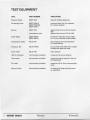
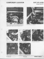
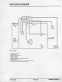
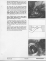
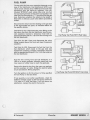
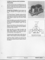
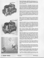
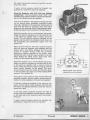
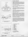
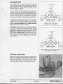
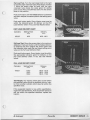
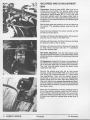
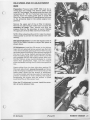
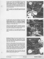
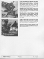
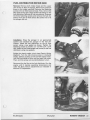
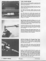
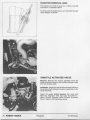
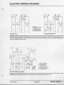
WORKSHOP MANUAL
Porsche
K-Jetronic
ROBERT BOSCH
CONTENTS
Test Equipment
Component Location
Vacuum Diagram
Trouble-Shooting Chart Vacuum Leaks
Component Tests
Air Flow Sensor Fuel Pump
Cold Start System Warm-Up Regulator System Pressure
Leakage Test Testing Injectors
Comparative Test Idle Speed and CO Adjustment Mounting Pressure Tester
Component Repair
Fuel Distributor Repair (911, 914)
Fuel Distributor Repair (928) Fuel Pump Repair
Pressure Regulator Repair Warm-up Regulator Repair (911)
Injector Removal (928) Throttle Activated Valve Electric Wiring Diagram Parts List
Test Sheet
2
ROBERT BOSCH
Porsche
4
5
9
10
11
12
17
18
19
22
23
23
24
26
30
32
33
34
35
35
36
36
37
39
40
K-Jetronic
INTRODUCTION
Testing Procedures . The construction and operation of the K-Jetronic (CIS) fuel injection system is
different from other fuel injection systems . The
technical instruction booklet Fuel Injection - Continuous Injection System (CIS) at the back of the
manual describes the components and operation of
the K-Jetronic fuel injection system in detail . A
thorough understanding of the various components is required before working on K-Jetronic fuel
systems .
Before trouble-shooting, testing or adjusting the
K-Jetronic fuel injection system, the ignition system and the mechanical system of the engine
(compression, valve timing, etc .) must be within
specification and operating properly . Verify that
these systems are in proper working order before
proceeding further.
K-Jetronic fuel systems have an electric safety
circuit which prevents the electric fuel pump and
other electrical devices from operating unless the
engine is running or being started . The electric
safety circuit can be bridged to apply voltage to any
electrical component without running or starting
the engine . This procedure can be found in the
Electric Wiring Diagram section of the manual .
In addition, 911 SC models use a thermo-valve,
which enriches the fuel mixture during starting by
blocking the warm-up regulator vacuum which decreases control pressure . After starting, the valve
opens by means of an electric heating element .
Always use new gaskets, seals and 0-rings when
installing components or fuel lines .
When installing the mixture control unit, tighten the
fastening screws uniformly.
Whenever work is performed on the fuel injection
system, the idle and CO must be adjusted .
How to use this manual . Use the trouble-shooting
chart to find the cause(s) for a given symptom . The
cause column will indicate what component(s)
should be tested . Each component test instruction is
a complete instruction . One component may be
checked by following the test instructions for the
specific component, or the entire system can be
checked by following all the component instructions
in order.
The Tool List and Component Location sections will
help identify the necessary tools and help locate
vehicle components to be tested . Specific component removal and installation information can be
found in Mounting the Pressure Tester and Component Repair The Electric Wiring Diagram section
shows how to bridge the electric safety circuit to
apply voltage to electrical components without running the engine . Replacement parts lists and complete test specifications can be found at the end of
the workshop manual .
Several component tests (Auxiliary Air Valve and
Warm-up Regulator) require that the engine is cold .
For cold tests, the engine must not have been run
for several hours, preferably overnight .
Most vehicles since 1978 have fuel distributors
which use push valves
in the system pressure
regulator to maintain pressure . Several component
tests require special testing procedures for fuel
distributors with push valves . The Fuel Pump section describes in detail how to identify a fuel distributor with a push valve in the system pressure
regulator.
Thoroughly clean the fuel fittings before removing
any fuel lines . Dirt must not enter the fuel system
under any circumstances . Do NOT bend the steel
fuel lines . When removing fuel lines, always hold
the hex fitting on the component with one wrench
while loosening the fuel line with another wrench .
Do not bend the steel type fuel lines .
K-Jetronic
Porsche
ROBERT BOSCH
3
TEST EQUIPMENT
TOOL
PART NUMBER
APPLICATION
Pressure Tester
KDEP 1034
tests all working pressures
Connecting Parts
KDEP 1034/10
KDEP 103411013
KDEP 1034/11
pressure tester fuel line adapters
for various engines
Wrench
KDEP 1035
manufacturer tool
adjusts idle mixture (CO) all except
928
adjusts idle mixture (CO) for 928
Guide Rings
KDEP 1040/10
KDEP 1040114
for 80 mm diameter sensor plates
for 110 mm diameter sensor plates
Comparative Tester
KDJE 7451
tests injectors and fuel distributor
for equal delivery
Accessory Set
KDJE 7451/25
for use with KDJE 7451 when engine
is fitted with steel fuel lines
Valve Tester
KDJE 7452
tests injectors
1500 cc Graduate
commercially available
measures fuel pump delivery
Tachometer
commercially available
measures engine speed for idle and
CO adjustment
CO meter
commercially available
measures CO for fuel mixture adjustment
Vacuum Pump
commercially available
for testing full load enriched warmup regulators
4 ROBERT BOSCH
Porsche
K-Jetronic
COMPONENT LOCATION
911T, 911,911S
through model 1975
Mixture Control Unit (1), Injectors (2) . The Start Valve is located on back
of intake manifold below the venturi assembly . The Thermo-time
Switch is located on engine block below the secondary air pump .
Warm-up Regulator (1)
Fuel Pump Test Point (arrow)
Electric Fuel Pump
Secondary Air Pump Pressure Hose (arrow)
K-Jetronic
Porsche
Bridging Electric Safety Circuit
ROBERT BOSCH 5
COMPONENT LOCATION
911,911s, 911SC
beginning model 1976
Mixture Control Unit with Air Filter Removed (1), Throttle Valve Assembly (2), Intake Housing (3), Secondary Air Pump (4)
Fuel Pump Protective Cover (above), Fuel Pump
(below)
6
ROBERT BOSCH
Fuel Pump Test Point (arrow)
Porsche
Injectors (5), Auxiliary Air Valve (6)
CO Test Point for Vehicles with Catalytic Converter
K-Jetronic
924
COMPONENT LOCATION
.4
yl
1
2
3
4
5
6
Nv
= Start Valve (hidden)
= Warm-up Regulator
= Auxiliary Air Valve
= Injectors
= Fuel Filter
= Mixture Control Unit
p
17,
Thermo-time Switch (aii
underneath engine
. viewed from
Fuel
cumulatois
Dampers (3)
,
Noise
Exhaust Gas Ac ii
(arrow)
il,itiun b
a-
11
Fuel Pump and Fuel Accumulator - 1976 model
K-Jetronic
Fuel Pump Test Point (arrow)
Porsche
Secondary Air Pump Pressure Hose (arrow)
ROBERT BOSCH
7
COMPONENT LOCATION
Start Valve (1), Auxiliary Air Valve
(4),Warm-up Regulator (5)
(2), Thermo-time Switch (3), Injector
928
Mixture Control Unit
Fuel Pump Protective Cover (above), Fuel
Pump No . 1 (below)
Fuel Accumulator and Fuel Filter - located in
right rear wheel well
tl
Fuel Pump No . 2 - located under right rear
fender
Fuel Pump Test Point (arrow)
Bridging Electric Safety Circuit, relay No . XVII
(arrow)
Porsche
K-Jetronic
8
ROBERT BOSCH
VACUUM
DIAGRAM
it
11
Ill
F-1
8
b
-Lzz:z"
[74
6
10
t
I
911 since 1976
1 =Throttle Valve Assembly
2=Electro Air Valve
3 =Auxiliary Air Valve
4=Thermo-valve (only 911 SC)
5=Warm-up Regulator
6= Ignition Distributor
7 =Exhaust Gas Recirculation Valve (only California)
8= Changeover Dump Valve
9=Vacuum Limiter
10=Vacuum Takeoff for Auxiliary Air Valve and Auxiliary Air Device
11 =Vacuum Takeoff Power-assisted Brake System
K-Jetronic
Porsche
ROBERT BOSCH
9
TROUBLE-SHOOTING CHART
F
CD
•
c
0°
a a
q
y
°
r
o
h
-
•
~c
y
0,
c
•
\a
a
~a
'&P
c
o`
°
a
wa
y
h
y
o
\a
y
a
sc`a
.,y
° c
s'
.
~,
clb ~ ,o°
moo°•
J0
`
°
c
y
y
~Q
~a
c
0,
a
0,
c
.
+L~
c
by
0
°
\~'
\a
\a
Causes)
10-
0-
t
t
0-
Vacuum system leaking (see Vacuum Leaks)
0~
Air flow sensor plate and/or control plunger not moving
smoothly (see Air Flow Sensor Movement)
Air flow sensor plate stop incorrectly set (see Air Flow
Sensor Position)
Auxiliary air valve does not open (see Auxiliary Air Valve)
Auxiliary air valve does not close (seeAuxiliaryAir Valve)
mo.
Electric fuel pump not operating (see Fuel Pump)
Defective cold start system (see Cold Start System)
IN.
Leaking cold start valve (see Cold Start System)
0-
Incorrect cold control pressure (see Warm-up Regulator)
Warm control pressure too high (see Warm-up
Regulator)
10.
11-
Do-
0-
IIN-
No.
Warm control pressure too low (see Warm-up Regulator)
Incorrect system pressure (see System Pressure)
0-
Fuel system pressure leakage (see Fuel Leaks)
10
.
0
00
No.
No
11o
.
Injection valve(s) leaking, opening pressure too low (see
Testing Injectors)
.
.
Unequal fuel delivery between cylinders (see
Comparative Test)
Basic idle and/or CO adjustment incorrect (see Idle and
CO Adjustment)
Throttle plate does not open completely
10 ROBERT BOSCH
Porsche
K-Jetronic
VACUUM LEAKS
There must be no air leaks in the air intake system .
Any air drawn into the engine without passing
through the air flow sensor will cause a lean air-fuel
mixture condition and improper engine operation .
To test for air leaks, remove the outlet hose from the
auxiliary air valve and pressurize the hose with compressed air. Hold the throttle plate open and coat all
air fittings (arrows below) with soapy water . Bubbles
indicate a leak.
Replace any defective hoses, gaskets or seals .
K-Jetronic
Porsche
ROBERT BOSCH
11
AIR FLOW SENSOR (updraft only)
Sensor Plate/Plunger Movement . Engine temperature
must be above 20° C (68° F) . Remove the rubber boot
from the air flow sensor . Bridge the electric safety
circuit (see Electric Wiring Diagram) . Switch the ignition on for 10 seconds to apply control pressure to the
plunger .
Fully lift the sensor plate up by hand to its maximum
deflection as shown . Even resistance must be felt over
the entire lever movement . If not, the air flow sensor
plate is not moving freely, (see below) .
Now push the sensor plate down rapidly, almost back
to its rest position . The plunger will not follow the
rapidly moving sensor plate, but the shock of the
plunger hitting the sensor plate lever when it does
come down must be felt . If this cannot be felt, the
plunger is not moving freely, (see below) .
Fully lift the air flow sensor plate up to its maximum
deflection . When released, the sensor plate must fall
back to its rest position after bouncing once or twice
on the spring stop . If not, the air flow sensor plate is
not moving freely, (see below) .
If the air flow sensor plate does not move freely,
loosen the mounting screws around the air flow
sensor housing to check if housing warpage is causing the lever to bind . If necessary, replace the gasket
under the air flow sensor and uniformly tighten the
fastening screws .
If the plunger does not move freely, remove the fuel
distributor from the air flow sensor (see Fuel Distributor Repair) . Remove the plunger from the fuel
distributor. If it is necessary to blow compressed air in
the control pressure connection hole to free the
plunger, hold the plunger with your hand as shown to
prevent the plunger from falling out of the fuel distributor. Clean the plungerwith an appropriate solvent .
If the plunger still binds in its barrel, replace the fuel
distributor.
12 ROBERT BOSCH
Porsche
K-Jetronic
Air Flow Sensor Plate Position . Remove the rubber
boot from the air flow sensor . The sensor plate must
be flat and pass through the narrowest part of the
funnel without touching the sides .
If the sensor plate touches the sides of the funnel,
loosen the sensor plate fastening screw . Insert the
appropriate guide ring (see Too/List) . Hold the fastening screw with pliers to prevent the plate from moving
down as shown . When the guide ring is in place,
tighten the fastening screw to 5 .0 - 5 .5 Nm (3 .7 - 4.0 ft
Ibs) . Then, loosen the screw and retorque the fastening screw again to the same value . The air flow sensor
plate must not now be able to be turned by hand .
Bridge the electric safety circuit (see Electric Wiring
Diagram) . Switch the ignition on for 10 seconds to
apply control pressure to the plunger .
The upper edge of the sensor plate should be flush
with the beginning of the upper cone as shown . The
upper edge of the sensor plate may be as much as 0 .5
mm below the beginning of the upper cone, but must
NOT project up into the cone at all .
Adjust the sensor plate position by removing the air
filter and bending the wire loop on the spring stop
(arrow) or turning the adjusting screw (1) . Tighten the
lock nut before rechecking the sensor plate position .
K-Jetronic
Porsche
ROBERT BOSCH 13
AIR FLOW SENSOR (downdraft only)
Sensor Plate/Plunger Movement . Engine temperature
must be above 20° C (68° F) . Remove the air filter from
the air flow sensor . Bridge the electric safety circuit
(see Electric Wiring Diagram) . Switch the ignition on
for 10 seconds to apply control pressure to the
plunger .
Fully push the sensor plate down by hand to its
maximum deflection as shown . Even resistance must
be felt over the entire lever movement . If not, the air
flow sensor plate is not moving freely, (see below) .
Now pull the sensor plate up rapidly, almost back to
its rest position . The plunger will not follow the
rapidly moving sensor plate, but the shock of the
plunger hitting the sensor plate lever when it does
come down must be felt . If this cannot be felt, the
plunger is not moving freely, (see below) .
Fully push the air flow sensor plate down to its
maximum deflection . When released, the sensor plate
must fall back to its rest position after bouncing once
or twice on the spring stop . If not, the air flow sensor
plate is not moving freely, (see below) .
If the air flow sensor plate does not move freely,
loosen the mounting screws around the air flow
sensor housing to check if housing warpage is causing the lever to bind . If necessary, replace the gasket
under the air flow sensor and uniformly tighten the
fastening screws .
If the plunger does not move freely, remove the fuel
distributor from the air flow sensor (see Fuel Distributor Repair) . Remove the plunger from the fuel
distributor. If it is necessary to blow compressed air in
the control pressure connection hole to free the
plunger, hold the plunger with your hand as shown to
prevent the plunger from falling out of the fuel distributor. Clean the plunger with an appropriate solvent .
If the plunger still binds in its barrel, replace the fuel
distributor.
14 ROBERT BOSCH
Porsche
K-Jetronic
Air Flow Sensor Plate Position . Remove the air filter
from the air flow sensor . The sensor plate must be
flat . The chamfered edge of the sensor plate must face
down . The word 'top' or five punch marks are
stamped on the top of the sensor plate .
The sensor plate must pass through the narrowest
part of the funnel without touching the sides . If the
sensor plate touches the sides of the funnel, loosen
the sensor plate fastening screw . Insert the appropriate guide ring (see Too/List) . Hold the fastening screw
as shown to prevent the sensor plate from moving
down . When the guide ring is in place, tighten the
fastening screw to 5 .0 - 5 .5 Nm (3 .7 - 4 .0 ft Ibs) . Then,
loosen the screw and retorque to the same value . The
air flow sensor plate must not now be able to be
turned by hand .
Bridge the electric safety circuit (see Electric Wiring
Diagram) . Switch the ignition on for 10 seconds to
apply control pressure to the plunger .
The upper edge of the sensor plate should be flush
with the beginning of the upper cone as shown . The
upper edge of the sensor plate may project up as
much as 0 .5 mm above the beginning of the upper
cone, but the lower edge of the sensor plate (above
the chamfer) must not project down into the lower
cone at all .
If the sensor plate is too high, very carefully tap the
guide pin (arrow) deeper into the housing . Caution :
Make this adjustment very carefully . Adjustment several times in both directions will loosen the press fit of
the pin, possibly causing engine damage .
K-Jetronic
Porsche
K
NW
4
ROBERT BOSCH 15
AUXILIARY AIR VALVE
Cold Operation . Test the auxiliary air valve first with
the engine cold (not run for several hours, preferably
overnight) . Disconnect the electric plug from the auxiliary air valve and from the warm-up regulator . Remove both air hoses from the auxiliary air valve .
Using a flashlight and a mirror, look through the valve
as shown . When the engine is cold, the valve must be
open . If not, replace the auxiliary air valve .
Warm Operation . Attach the electric plug to the auxiliary air valve . Bridge the electric safety circuit (see
Electric Wiring Diagram) . Turn the ignition on . The
auxiliary air valve must be completely closed within
10 minutes.
If the auxiliary air valve does not completely close
within 10 minutes, test the supply voltage (approximately 11 .5 volts, ignition off) available to the auxiliary air valve at the electric plug .
If sufficient voltage is available to the auxiliary air
valve and the valve still does not close, replace the
auxiliary air valve .
16 ROBERT BOSCH
Porsche
K-Jetronic
FUEL PUMP
The test point for fuel pump operation depends on the
type of fuel distributor . Fuel distributors WITH push
valves (most vehicles since 1978) have two fuel lines
connecting with the warm-up regulator . Fuel distributors WITHOUT push valves have only one fuel
line connecting directly to the warm-up regulator ; the
other fuel line connects to a "T" and returns to the gas
tank. Determine whether the vehicle to be tested is
fitted with or without a push valve before proceeding
further.
-I∎K,
~= z
1
=Z=
Disconnect the return fuel line leading to the gas tank
at the appropriate test point, as indicated below for
the specific vehicle .
Test Point for 911 : Disconnect the union fitting on the
fuel return line from the fuel distributor (see Compo-
nent Location) . Connect a temporary hose with an
appropriate fitting (M 14 x 1 .5) to the line coming from
the fuel distributor .
Fuel Pump Test Point WITH Push Valve
Test Point for 924 : Clean and disconnect the union
fitting located above the front axle (see Component
Location) .
Test Point for 928: Disconnect the fuel line from the
H
fuel distributor which leads to the gas tank (see
Component Location) . Connect a temporary fuel line
with an appropriate fitting (M 14 x 1 .5) to the outlet on
the fuel distributor .
Hold the line coming from the fuel distributor in a
1500 cc or larger graduate . Inflexible metal fuel lines
may require a rubber hose to reach the graduate .
Remove the electric plug from the warm-up regulator
and the auxiliary air valve . Bridge the electric safety
circuit (see Electric Wiring Diagram) .
Turn the ignition on for the amount of time specified
for Fuel Pump on the test sheet .
Fuel Pump Test Point WITHOUT Push Valve
If fuel quantity is not within specification, check for
sufficient voltage supply to the fuel pump (minimum
11 .5 volts) or a dirty fuel filter . If all the above are
satisfactory, replace the electric fuel pump .
K-Jetronic
Porsche
ROBERT BOSCH 17
COLD START SYSTEM
Thermo-Time Switch . This instruction applies only to
Robert Bosch thermo-time switches .
Remove the thermo-time switch from the engine .
Engine coolent will spill out when the switch is removed from the engine . Find the design number
stamped on the flats of the thermo-time switch housing . Use the design number to find the appropriate
test values from the thermo-time switch chart below .
Using an ohmmeter, check the resistance at both .
temperatures indicated on the thermo-time switch
chart . Use warm water to heat the switch as required .
If any resistance does not fall within the specified
tolerance, replace the thermo-time switch .
THERMO-TIME SWITCH CHART
Design Number
Temperature
45° C/9 .5 s
below 104° F
30 - 40
55 - 85
0
120 - 160
below 86° F
above 104° F
25 - 40
50 - 80
0
100 - 160
50 - 80
below 55° F
above 73° F
50 - 70
50 - 70
0
infinite
50 - 70
50 - 70
below 50 ° F
above 68 ° F
50 - 70
50 - 70
0
infinite
infinite
above 122° F
35° C/8 s
18° C/8 s
15 ° C/8 s
Resistance in ohms
from terminal from terminal from terminal
G to Ground W to Ground
G to W
30-40
55 - 85
25 - 40
infinite
Cold Start Valve . Disconnect the electric plug from
the cold start valve . Remove the cold start valve from
the intake manifold . Hold the cold start valve in a
graduate . A rubber hose may be required to reach the
graduate .
Temporarily connect one start valve terminal to
ground and the other terminal to the "+" terminal of
the ignition coil . Bridge the electric safety circuit (see
Electric Wiring Diagram) . Turn the ignition on for not
more than 30 seconds . If the cold start valve does not
spray, replace the cold start valve . Caution : Keep the
cold start valve and connecting wires away from the
"+" battery terminal to prevent sparking .
Turn the ignition off and disconnect the temporary
electrical wires from the cold start valve . Wipe the
cold start valve dry . With the electric safety circuit still
bridged, switch the ignition on for one minute . If the
cold start valve drips or leaks, replace the cold start
valve .
18 ROBERT BOSCH
Porsche
K-Jetronic
WARM-UP REGULATOR (CONTROL
PRESSURE)
Porsche uses several warm-up regulators on its vehicles . The testing procedure and test specifications are
different for each type of warm-up regulator. Find the
warm-up regulator type to be tested from the ones
listed below and proceed with the test instructions for
that specific type .
Standard Warm-Up Regulator. Connect pressure tester KDEP 1034 (see Mounting Pressure Tester) . Use
the test specification for the specific warm-up regulator .
Cold Control Pressure : The engine must be cold (not
run for several hours, preferably overnight) . Disconnect the plug from the warm-up regulator . Open both
valve screws on the three-way valve of the pressure
tester . Bridge the safety circuit (see Electric Wiring
Diagram) .
Switch the ignition on to run the electric fuel pump
and read the cold control pressure on the gauge . The
pressure must be within the tolerance band given on
the appropriate test specification graph . Turn the
ignition off.
to pressure gauge
f
Warm Control Pressure : Engine temperature is not
important . Attach the plug to the warm-up regulator .
Bridge the safety circuit . Open both valve screws on
the pressure tester as shown .
Switch the ignition on to operate the electric fuel
pump . When the pressure stops increasing, read
warm control pressure on the gauge . The warm
control pressure must be within the tolerance given
on the test sheet . Turn the ignition off.
If the warm control pressure does not fall within the
specified tolerance, test the supply voltage (approximately 14 volts) available to the warm-up regulator .
f
to warm-up
regulator
KDEP 1034
from fuel
distributor
Opening Both Valve Screws
(measuring control pressure)
If sufficient voltage is available to the warm-up regulator, and the warm control pressure still does not
fall within the specified tolerance, replace the warmup regulator .
K-Jetronic
Porsche
ROBERT BOSCH 19
,e!P Vacuum
Warm-Up Regulator with Full Load Enrichment . Connect pressure tester KDEP 1034 (see Mounting Pressure Tester) . Use the test specification for the specific
warm-up regulator .
Cold Control Pressure : The engine must be cold (not
run for several hours, preferably overnight) unless
otherwise indicated on the test sheet . Disconnect the
plug from the warm-up regulator . Open both valve
screws on the three-way valve of the pressure tester .
Bridge the safety circuit (see Electric Wiring Diagram) .
Switch the ignition on to run the electric fuel pump .
Apply the vacuum indicated on the test sheet (if any)
to the warm-up regulator with a vacuum pump as
shown . The cold control pressure indicated on the
gauge must be within the tolerance band shown on
the appropriate test specification graph . Turn the ignition off .
43 Atmosphere
Warm Control Pressure : Test warm control pressure
with the warm-up regulator plug attached . Engine
temperature is not important . Bridge the safety circuit . Open both valve screws on the pressure tester as
shown .
Switch the ignition on to run the electric fuel pump .
Apply the vacuum indicated on the test sheet (if any)
to the warm-up regulator with a vacuum pump as
shown . When the pressure stops increasing, read the
warm control pressure on the gauge . The warm
control pressure must be within the tolerance given
on the test sheet . Turn the ignition off .
Warm Control Pressure WITH Throttle Activated
Valve: Test warm control pressure with the warm-up
regulator plug attached . Position throttle plate against
idle stop .
Switch the ignition on to run the electric fuel pump .
When the pressure stops increasing, read the warm
control pressure on the gauge . If the warm control
pressure is not within the tolerance given for idle on
the test sheet, remove both fastening screws on the
throttle activated valve and turn the valve in the area
of the slots . If the idle value cannot be obtained,
replace the throttle activated valve and readjust to the
value given for idle on the test sheet.
Position the throttle plate by hand about halfway . If
the pressure does not rise to the partial load value
given on the test sheet, replace the warm-up regulator .
Completely open the throttle to the full load position .
If the pressure does not drop to the full load value
given on the test sheet, replace the throttle activated
valve and recheck the idle pressure .
If the warm control pressure does not fall within the
specified tolerance, test the supply voltage (approximately 14 volts) available to the warm-up regulator .
If sufficient voltage is available to the warm-up regulator, and the warm control pressure still does not
20 ROBERT BOSCH
Porsche
K-Jetronic
fall within the specified tolerance, check the vacuum
source for a leak .
If warm control pressure cannot be brought into
specification, replace the warm-up regulator .
Warm-Up Regulator with Full Load and Altitude
Compensator. Connect pressure tester KDEP 1034
(see Mounting Pressure Tester) . Use the test specification for the specific warm-up regulator .
Cold Control Pressure: The engine must be cold (not
run for several hours, preferably overnight) unless
otherwise indicated on the test sheet . Disconnect the
plug from the warm-up regulator . Open both valve
screws on the three-way valve of the pressure tester .
Bridge the safety circuit (see Electric Wiring Diagram) .
Switch the ignition on to run the electric fuel pump .
Apply the vacuum indicated on the test sheet (if any)
to the warm-up regulator with a vacuum pump as
shown . The cold control pressure indicated on the
gauge must be within the tolerance band shown on
the appropriate test specification graph . Turn the
ignition off.
to pressure gauge
Warm Control Pressure : Test warm control pressure
with the warm-up regulator plug attached and the
engine warm . Use station pressure from the local
airport or weather bureau, NOT the corrected
barometric pressure reported to the public, when
reading the warm control pressure graph on the test
sheet . Bridge the safety circuit . Open both valve
screws on the pressure tester as shown .
Switch the ignition on to run the electric fuel pump .
Apply the vacuum indicated on the test sheet (if any)
to the warm-up regulator with a vacuum pump as
shown . When the pressure stops increasing, read the
warm control pressure on the gauge . The warm
control pressure must be within the tolerance given
on the test sheet (use upper curve when testing WITH
vacuum) . Turn ignition off.
f
F 1:
2
1
to warm-up
regulator
OO
3
KDEP 1034
f
from fuel
distributor
Opening Both Valve Screws
(measuring control pressure)
If the warm control pressure does not fall within the
specified tolerance, test the supply voltage (approximately 14 volts) available to the warm-up regulator .
If sufficient voltage is available to the warm-up regulator, and the warm control pressure still does not
fall within the specified tolerance, check the vacuum
source for a leak .
If the high control pressures required for high altitudes cannot be obtained, increase system pressure
to the high side of the tolerance band (see System
Pressure) .
If warm control pressure cannot be brought into
specification, replace the warm-up regulator .
K-Jetronic
Porsche
ROBERT BOSCH 21
SYSTEM PRESSURE
Testing System Pressure . Engine temperature is not
important . Connect pressure tester KDEP 1034 as
indicated in Mounting Pressure Tester . Bridge the
electric safety circuit (see Electric Wiring Diagram) .
Close the pressure tester valve screw leading to the
warm-up regulator as shown .
to pressure gauge
Turn the ignition on . Read the system pressure on the
gauge and compare this reading with the value
shown on the test sheet .
2
r
J
f
to warm-up
regulator
KDEP 1034
from fuel
distributor
Closing Valve Screw to Warm-up Regulator
(measuring system pressure)
If system pressure is lower than the value given on
the test sheet, test the fuel pump . If the fuel pump is
within specification, adjust the system pressure as
indicated below .
If system pressure is higher than the value shown on
the test sheet, check the gas tank return line for a
restriction . If there is no restriction in the return line,
adjust the system pressure .
Adjusting System Pressure . If the fuel distributor is
fitted WITH a push valve, unscrew the large screw
plug with attached push valve assembly . Change the
adjusting shim as required . A 0 .1 mm increase in shim
thickness will increase system pressure 0 .15 bar (2 .2
PSI) . Use a new O-ring and copper gasket when
reinstalling the large screw plug and push valve .
Note : The piston in front of the shim is matched to the
housing and is not replaceable.
SYSTEM PRESSURE REGULATOR
(without push valve)
If the fuel distributor is fitted WITHOUT a push valve,
remove the screw plug and change the adjusting shim
as required . A 0 .1 mm increase in shim thickness will
increase system pressure 0 .15 bar (2 .2 PSI) . Use a new
copper gasket when installing the screw plug . Tighten
the screw plug to 13 - 15 Nm (10 - 11 ft Ibs) . Note : The
piston in front of the shim is matched to the housing
and is not replaceable.
1 = Fuel distributor housing
2 = 0-ring
3 = Control piston
4 = Spring
5 = Retainer
6 = Retaining ring
7 = Spring
8 = Shims
10 = Valve needle
11 = Seal ring
12 = Screw plug
13 = Screw plug
14 = Flat seal ring
a = from fuel distributor
b = from warm-up regulator
c = fuel return
22 ROBERT BOSCH
Porsche
K-Jetronic
LEAKAGE TEST
The engine must be warm, but not hot . Connect
pressure tester KDEP 1034 (see Mounting Pressure
Tester) . Bridge the electric safety circuit (see Electric
Wiring Diagram) . Open both valve screws on the
three-way valve as shown .
to pressure gauge
f
Turn the ignition on . When warm control pressure is
reached, turn the ignition off. After the specified time,
the control pressure must NOT be less than the value
given on the test sheet for leakage test . If control
pressure drops too quickly, close the valve leading to
the warm-up regulator and repeat the leakage test .
If closing the valve leading to the warm-up regulator
brings the pressure into specification, replace the push
valve, or for fuel distributors without push valves, replace the warm-up regulator and/or throttle activated
valve if fitted (see Component Repair) .
r
to warm-up
1O O3
f
KDEP 1034
regulator
from fuel
distributor
Opening Both Valve Screws
(measuring control pressure)
If closing the valve leading to the warm-up regulator
does NOT bring the pressure into specification, there is
a leak in the system pressure circuit . Check the cold
start valve for leakage (see Cold Start Valve) . Test the
injectors for leakage (see Testing Injectors) . If necessary, replace the check valve on the electric fuel pump
and/or the control piston 0-ring on the system pressure regulator in the fuel distributor (see Fuel Distributor Repair) .
to pressure gauge
I
2
r
to warm-up
regulator
1O
O
3
KDEP 1034
J
from fuel
distributor
Closing Valve Screw to Warm-up Regulator
(measuring system pressure)
TESTING INJECTORS
Remove the injectors from the engine . Connect each
injector to valve tester KDJE 7452 as indicated in the
operating instructions included with the tester . Injectors should be tested for opening pressure, leakage
and spray pattern . Replace any defective injectors .
K-Jetronic
Porsche
ROBERT BOSCH 23
COMPARATIVE TEST
Setting up the tester. Comparative tester KDJE 7451
is used to measure equal delivery between injectors .
The comparative test will also determine whether a
problem involves an injector or the fuel distributor .
Set the tester on a solid surface next to the e
v hicle .
Level the tester and install the return hose in the gas
tank .
If inflexible steel fuel lines are used on the vehicle,
remove the steel lines from both the injector and the
fuel distributor, and replace them with flexible adapter
hoses from accessory kit KDJE 5471/25 .
Remove the injectors from the engine and insert each
injector, in order, into the tester fuel lines . Tighten the
knurled coupling to secure each injector .
Remove the rubber boot (updraft) or air filter
(downdraft) from the upper part of the air flow sensor .
Bridge the electric safety circuit (see Electric Wiring
Diagram) .
Switch the ignition on to operate the fuel pump . Move
the sensor plate to its maximum deflection . Press
each of the eight buttons while turning the load range
knob back and forth until the rotameter tubes are
completely bled . Return the sensor plate to its rest
position .
Idle Test . Turn the load range knob to the left to read
the left rotameter tube . Press button number 1 .
Move the air flow sensor plate by hand until the left
rotameter tube shows the value given for setting
point on the Idle Delivery Chart . Fix the sensor plate in
this position .
Push each button one after the other until the lowest
delivery is obtained and then readjust the sensor plate
to the setting point value .
Push each button again . Every injector must now be
w thin the tolerance given for delivery on the Idle
i
Delivery Chart . If not, see Test Results below .
IDLE DELIVERY CHART
Cylinders
4,5,6
8
24
ROBERT BOSCH
Porsche
Setting Point
Delivery
cc/min
cc/min
6 .0
6 .0
6 .0-6 .8
6 .0-7 .0
K-Jetronic
Part Load Test. Turn the load range knob to the right
to read the right rotameter tube . Press button number
1 . Move the sensor plate by hand until the right
rotameter tube shows the value given for setting
point on the Part Load Delivery Chart . Fix the sensor
plate in this position .
Push each button n
u til the lowest delivery is obtained
and then readjust the sensor plate to the setting point
value .
Push each button again . Every injector must now be
within the tolerance given for delivery on the Part
Load Delivery Chart . If not, see Test Results below .
PART LOAD DELIVERY CHART
Cylinders
Setting Point
cc/min
Delivery
cc/min
4,5,6,8
40 .0
40 .0-44 .0
Full Load Test. Move the sensor plate to its maximum
deflection . Push each button until the highest delivery
is obtained and then readjust the sensor plate until
the rotameter tube reads the next lower setting point
value on the Full Load Delivery Chart.
Push each button again . Every injector must be within
the appropriate tolerance given for delivery on the
Full Load Delivery Chart. If not, see Test Results
below.
FULL LOAD DELIVERY CHART
Cylinders
4,5,6,8
Setting Point
cc/min
120 .0
140.0
160.0
Delivery
cclmin
120 .0 - 131 .0
140 .0 - 153 .0
160 .0 - 175 .0
Test Results. Any injector which does not fall within
the specified value should be switched with an injector from another cylinder which does fall within the
specified value .
If the suspected injector is now within specification,
replace the fuel distributor. If the suspected injector is
still not within the specified tolerance, replace the
injector.
K-Jetronic
Porsche
ROBERT BOSCH 25
IDLE SPEED AND CO ADJUSTMENT
(911 with throttle activated valve)
CO mixture screw
i~^hyM~'*
Idle by-pass
screw
'N
Preparation . Pressure tester KDEP 1034 must be removed from the vehicle . The electric safety circuit
must NOT be bridged . The engine must be warm . If
any fuel lines have been opened, warm the engine
under load to purge the lines of air . Idle speed and CO
specifications are given on the emissions decal in the
vehicle engine compartment .
Vehicles with Secondary Air Pump : Remove and plug
the pressure hose on the air pump .
Vehicles with Vacuum Limiter: Remove and plug the
air hose which connects with the "T" connection
above the throttle plate .
ADJUSTING SCREWS
Idle Speed Adjustment. Turn the idle bypass screw
(arrow) to adjust idle speed .
CO Adjustment . Make the CO adjustment immediately after a test drive (engine at operating temperature) . Install the CO sensor in the tailpipe . Remove the sealing plug from the air flow sensor housing . Using wrench KDEP 1035, turn the CO mixture
screw out (counterclockwise) to a value leaner than
specification . Then, turn the mixture screw in
(clockwise) to bring the CO value into specification .
Always adjust from the lean side when setting CO .
After each adjustment, remove the wrench and accelerate the engine to stabilize the mixture . Accelerating
the engine with the wrench in p/ace could bend the air
flow sensor lever.
When the CO adjustment is correct, reconnect the
pressure hose to the secondary air pump . The CO
value must now be less than 1% . If not, clean the air
filter on the secondary air pump with compressed air.
Install the plug in the air flow sensor housing and
install the vacuum limiter air hose (if fitted) .
Testing Throttle Activated Valve . The 1973-74 911S
uses a throttle activated valve to energize the start
valve . Test the valve by attaching an ohmmeter to the
two electrical connections on the throttle activated
valve . In the idle position, the ohmmeter must read
infinity (circuit open) . When the hand throttle (between
the seats) is pulled all the way out, the ohmmeter must
read zero resistance (circuit closed) . If not, adjust the
throttle activated valve .
Adjusting Throttle Activated Valve . Insert a 2 mm
thick feeler gauge between the idle stop screw and the
stop boss . Holding the stop screw against the feeler
gauge, turn the stop screw until the throttle circuit just
closes (zero resistance on the ohmmeter) . It must be
possible to press the throttle activated valve switch
lever a minimum of 0 .5 mm farther downward . Then
check again that the electric circuit is closed (zero
resistance) when the hand throttle lever is fully pulled .
26
ROBERT BOSCH
Porsche
K-Jetronic
IDLE SPEED AND CO ADJUSTMENT
(911 since 1976)
Preparation . Pressure tester KDEP 1034 must be removed from the vehicle . The electric safety circuit
must NOT be bridged . The engine must be warm . If
any fuel lines have been opened, warm the engine
under load to purge the lines of air. Idle speed and CO
specifications are given on the emissions decal in the
vehicle engine compartment . On 911SC models,
make sure the oil tank cover is sealing properly . A
leaking oil tank cover will allow unmetered intake air
to enter the engine .
Vehicles with Secondary Air Pump : Remove and plug
the hose on the secondary air pump check valve as
shown .
Vehicles with Vacuum Limiter. Remove and plug the
air hose which connects with the "T" connection
above the throttle plate.
Idle Speed Adjustment. Turn the idle bypass screw
(arrow) to adjust idle speed .
CO Adjustment Install the CO sensor in the tailpipe . If
the vehicle has a catalytic converter, install the sensor
in the screw plug hole ahead of the converter. This hole
must be sealed around the sensor when reading the
CO meter.
Remove the sealing plug from the air flow sensor
housing . Using wrench KDEP 1035 as shown below,
turn the CO mixture screw out (counterclockwise) to a
value leaner than specification . Then, turn the mixture screw in (clockwise) to bring the CO value into
specification . Always adjust from the lean side when
setting CO . After each adjustment, remove the
wrench and accelerate the engine to stabilize the mixtu re . Accelerating the engine with the wrench in place
could bend the air flow sensor lever
When the CO adjustment is correct, install the plug in
the air flow sensor housing, install the secondary air
pump pressure hose (if fitted), install the vacuum
limiter air hose (if fitted) and install the exhaust pipe
screw plug (if fitted) .
K-Jetronic
Porsche
ROBERT BOSCH 27
IDLE SPEED AND CO ADJUSTMENT
(924)
Preparation . Pressure tester KDEP 1034 must be removed from the vehicle . The electric safety circuit
must NOT be bridged . The engine must be warm (oil
temperature approximately 80 0 C) . If any fuel lines
have been opened, warm the engine under load to
purge the lines of air. Idle speed and CO specifications
are given on the emissions decal in the vehicle engine
compartment .
Both throttle plate rest positions are set and sealed at
the factory . The adjusting screws must not be adjusted .
Clamp the hose between the carbon canister and the
air filter as shown above .
Vehicles i
w th Exhaust Gas Recirculation : Remove and
plug the a
v cuum hose on the EGR valve .
Vehicles with Secondary Air Pump : Remove and plug
the pressure hose on the air pump .
Vehicles with Vacuum Limiter. Remove and plug the
air hose which connects with the "T" connection
above the throttle plate .
Idle Speed Adjustment. Turn the idle bypass screw
(arrow) to adjust idle speed . The throttle plate position
adjusting screws are sealed at the factory and must not
be altered .
CO Adjustment . Install the CO sensor in the tailpipe . If
the vehicle has a catalytic converter, install the sensor
(3) in the screw plug hole (1) ahead of the converter .
This hole must be sealed around the sensor when
reading the CO meter .
Remove the sealing plug from the air flow sensor
housing . Using wrench KDEP 1035, turn the CO mixture screw out (counterclockwise) to a value leaner
than specification . Then, turn the mixture screw in
(clockwise) to bring the CO value into specification .
Always adjust from the lean side when setting CO .
After each adjustment, remove the wrench and accelerate the engine to stabilize the mixture . Accelerating
the engine with the wrench in place could bend the air
flow sensor lever.
When the CO adjustment is correct, install the plug in
the air flow sensor housing, install the EGR vacuum
hose (if fitted), install the secondary air pump pressure hose (if fitted), install the vacuum limiter air hose
(if fitted) and install the exhaust pipe screw plug (if
fitted) .
28 ROBERT BOSCH
Porsche
K-Jetronic
IDLE SPEED AND CO ADJUSTMENT
(928)
Preparation . Pressure tester KDEP 1034 must be removed from the vehicle . The electric safety circuit
must NOT be bridged : The engine must be warm (oil
temperature 80 - 90° C) . If any fuel lines have been
opened, warm the engine under load to purge the
lines of air . Idle speed and CO specifications are given
on the emissions decal in the vehicle engine compartment .
Remove the upper part of the air filter (4 clamps) .
Remove the right hand air intake hose to expose the
secondary air pump. Then, remove and plug the
pressure hose on the secondary air pump . Replace
the upper part of the air filter and the air intake hose .
NOTE : When adjusting idle and CO, make the adjustments quickly to prevent the intake tubes from overheating .
Idle Speed Adjustment. Turn the idle bypass screw in
front of the intake manifold to adjust idle speed as
shown above .
CO Adjustment . Install the CO sensor in the tailpipe .
Insert a 3 mm spherical tip hex wrench (see Tool List)
in the funnel shaped opening of the air filter housing
as shown below until the tip of the wrench engages in
the top of the spring loaded sealing plug (arrow) .
Push the sealing plug down (about 18 mm) until the
plug engages with the idle mixture screw . Now, turn
the idle mixture screw counterclockwise to a value
leaner than specification . Then, turn the mixture
screw clockwise to bring the CO value into specification .
Always adjust from the lean side when setting CO .
After each adjustment, remove the wrench and accelerate the engine to stabilize the mixture and cool the
intake tubes . When the hex wrench is withdrawn,
the spring loaded sealing plug seals the opening to
prevent unmetered air from entering the engine .
Accelerating the engine with the wrench in place
could bend the air flow sensor lever
When the CO adjustment is correct, install the secondary air pump pressure hose .
K-Jetronic
Porsche
ROBERT BOSCH 29
MOUNTING PRESSURE TESTER
Preparation . Pressure tester KDEP 1034 was initially
supplied with a three-way changeover valve operated
by a single lever . In newer models this lever is
replaced by a directional control valve with two hollow screws . The connections on the directional control valve and the changeover valve are numbered the
same .
The pressure tester is connected in the control pressure line between the warm-up regulator and the fuel
distributor as shown .
For 91 .1S models with throttle activated valve : Clean
the fuel fittings on the warm-up regulator . At the fuel
distributor, unscrew both the control pressure line
coming from the throttle activated valve and the
control pressure line coming from the warm-up regulator . Using adapter KDEP 1034/10/1 and one of the
original hollow screws, attach both pressure lines to
connection 1 of the tester valve .
Screw connector piece KDEP 1034/10/2 into the control outlet hole of the fuel distributor. Attach connection 3 of the tester valve to the connection piece in the
fuel distributor .
Attach connection 2 to the pressure gauge with the
other connecting hose . Bleed the tester as indicated
below .
For911 models without throttle activated valve : Clean
the fuel fittings on the control pressure line at the fuel
distributor . Unscrew the control pressure line from
the fuel distributor. Using adapter KDEP 1034/10/3,
attach the control pressure line to connection 3 of the
valve tester .
Unscrew the fitting left in the control pressure outlet
of the fuel distributor and install connecting piece
KDEP 1034/10/2 in its place . Using a connecting hose,
attach connection 1 of the tester valve to the connecting piece in the fuel distributor .
Attach connection 2 to the pressure gauge with the
other connecting hose . Bleed. the tester as indicated
below.
30 ROBERT BOSCH
Porsche
K-Jetronic
For 924 models : Clean the fuel fittings for the control
pressure line on the fuel distributor . Unscrew the
control pressure line from the fuel distributor and
attach the line to connection 1 on the tester valve as
shown . Attach connection 3 of the tester valve to the
fuel distributor with the connecting hose . Attach connection 3 of the tester valve to the fuel distributor with
the connecting hose .
Attach connection 2 to the pressure gauge with the
other connecting hose . Bleed the tester as indicated
below.
For 928 models : Clean the fuel fittings on the control
pressure line at the warm-up regulator . Remove the
control pressure line from the warm-up regulator .
Using the hose included in connecting parts set KDEP
1034/11, connect the warm-up regulator outlet with
connection 1 of the tester valve .
Attach the two piece connector (included in connecting parts set KDEP 1034111) to the control pressure
line . Using the tester hose, connect the control pressure line to connection 3 of the tester valve .
Attach connection 2 to the pressure gauge with the
other connecting hose . Bleed the tester as indicated
below .
Bleeding the Tester . Disconnect the electric plug from
the warm-up regulator and the auxiliary air valve .
With the tester hoses fully extended, let the gauge
hang down under its own weight so that the gauge is
lower than the fuel lines .
Bridge the electric safety circuit and switch the ignition on to run the fuel pump . If the changeover valve
is used, move the control lever back and forth about
five times between position 2 and 3, remaining in
each position about 10 seconds . If the directional
control valve is used, open and close hollow screw
number 1 about five times, remaining in each position
approximately 10 seconds . Turn the ignition off.
Hang the gauge from one of the struts under the
engine hood or other suitable support and proceed
with the appropriate pressure test .
K-Jetronic
Porsche
ROBERT BOSCH
31
FUEL DISTRIBUTOR REPAIR (911,924)
Removal . Clean all the fuel fittings on the fuel distributor . Remove all fuel connections . Unscrew the
three fastening screws and remove the fuel distributor from the air flow sensor housing or throttle
valve housing . Be careful not to let the plunger fall
out . Keep shims and springs together .
Installation . When installing the 911 air flow sensor
housing on the intake manifold, tighten the fastening
screws until each spring is compressed, then loosen
each screw one turn .
Rinse the plunger in an appropriate solvent and
reinstall the plunger in the fuel distributor. Install the
fuel distributor on the air flow sensor using a new
gasket as shown . Tighten the fastening screws to
exactly 3 .2 - 3 .8 Nm (2 .4 - 2 .8 ft Ibs) . Attach all fuel
lines except one (arrow) to the fuel distributor using
new gaskets .
Bridge the electric safety circuit (see Electric Wiring
Diagram) . Turn the idle mixture screw in clockwise
slowly, without pushing on the air flow sensor lever,
until fuel just starts to come out the open fuel outlet .
Then, turn the screw out counterclockwise 1/2 turn .
Reconnect the fuel line to the fuel distributor . Run the
engine until it reaches operating temperature and
make the final mixture adjustments as indicated in
Idle and CO Adjustment.
32 ROBERT BOSCH
Porsche
K-Jetronic
FUEL DISTRIBUTOR REPAIR (928)
Removal . Remove both intake hoses and the upper
part of the air filter (4 clamps) . Remove the pressure
screw in the intake manifold . Remove the fastening
screws in the air filter bowl (arrows) . Then, remove the
filter bowl to the right . Clean all the fuel fittings on the
fuel distributor. Remove all fuel connections . Unscrew
the three fastening screws and remove the fuel distributor from the air flow sensor. Be careful not to let
the plunger fall out .
Installation. Rinse the plunger in an appropriate
solvent and reinstall the plunger in the fuel distributor . Install the fuel distributor on the air flow
sensor using a new gasket as shown . Tighten the
fastening screws to exactly 3 .2 - 3 .8 Nm (2 .4 - 2 .8 ft
lbs) . Attach all fuel lines except one (arrow) to the fuel
distributor using new gaskets .
Bridge the electric safety circuit (see Electric Wiring
Diagram) . Turn the idle mixture screw in clockwise
slowly, without pushing on the air flow sensor lever,
until fuel just starts to come out the open fuel outlet .
Then, turn the screw out counterclockwise 1/z turn .
Reconnect the fuel line to the fuel distributor . Run the
engine until it reaches operating temperature and
make the final mixture adjustments as indicated in
Idle and CO Adjustment.
K-Jetronic
Porsche
ROBERT BOSCH 33
FUEL PUMP REPAIR
Remove any dirt protection plates to expose the fuel
pump . See Component Location for exact position of
fuel pump components .
Clean all fuel fittings and clamp the inlet hose to
prevent fuel from escaping before removing any fuel
pump components .
On 1973-74 Porsche 911 models, remove the inlet
hose from the union fitting after loosening the hose
clamp .
On 1975 Porsche 911 models with polyamide fuel
lines, remove the fuel pump together with the complete fuel line . The inlet fuel line should be removed
from the pump on the bench . Hold the pump by hand,
NOT in a vise . Torque the union fitting to exactly 16 20 Nm (12 - 15 ft Ibs) .
Steel Housing with Side Fuel Fitting. Clean the fuel
fittings on the electric fuel pump . Remove and thoroughly clean the fuel pump . Mount the clamp for the
fuel pump in a vise as shown . Do NOT clamp the fuel
pump housing itself in a vise .
Unscrew the check valve from the side of the pump .
No dirt must enter the pump . Install a new check valve
using a new gasket and tighten to exactly 16 - 20 Nm
(12 - 15 ft Ibs) .
Aluminum Housing with Internal Check Valve . The
check valve on fuel pumps with internal check valves
cannot be replaced . If the check valve is leaking, the
complete fuel pump must be replaced .
Aluminum Housing with Threaded Check Valve .
Clean the fuel fittings and remove the fuel pump .
Unscrew the valve insert using a special slotted
screwdriver (9 mm wide blade, 4 mm wide slot) . No
dirt must enter the pump .
Install a new check valve using a new 0-ring and
tighten to 0 .4 - 0 .6 Nm (3 .5 - 5 .3 in lbs) . Be careful not
to overtightenn the check valve and damage the delicate plastic threads .
Caution : On 1976 and later Porsche 911 models, the
fastening screws which secure the protective plate
also fasten part of the front axle support and stabilizer
bar . Be sure to tighten the protective plate socket
head screws to 47 Nm (35 ft Ibs) and the protective
plate self-locking nuts to 28 Nm (21 ft Ibs) . Selflocking nuts which have been reused several times
should be replaced with new ones .
34 ROBERT BOSCH
Porsche
K- Jetronic
PRESSURE REGULATOR REPAIR
Clean the fuel distributor, especially around the system pressure regulator. Remove the screw plug (large
screw plug and push valve if fitted), shim, spring and
needle valve . Replace the O-ring behind the control
piston . Be careful not to damage the needle valve
during removal and assembly .
Install the control piston, spring, shim, (push valve if
fitted), and the screw plug using a new gasket .
Tighten the screw plug to 13 - 15 Nm (10 - 11 ft Ibs) .
Check the system pressure and adjust as necessary .
The needle valve and large screw plug on push valve
type distributors are only replaced together as a unit .
SYSTEM PRESSURE REGULATOR
(without push valve)
1 = Fuel distributor housing
2 = O-ring
3 = Control piston
4 = Spring
5 = Retainer
6 = Retaining ring
7 = Spring
8 = Shims
10 = Valve needle
11 = Seal ring
12 = Screw plug
13 = Screw plug
14 = Flat seal ring
a = from fuel distributor
b = from warm-up regulator
c = fuel return
WARM-UP REGULATOR REPAIR (911)
Removal . Remove intake hose 1 from the auxiliary fan
housing . Loosen hose clamps 2 and 3 and remove the
hoses from the auxiliary fan housing . Note : 911SC
models require removal of a plastic rivet in each hose .
Loosening screw 4 and tilting the fan motor upwards
will make the hose removal easier .
Installation. Replace the warm-up regulator as required and reassemble in the reverse order.
K-Jetronic
Porsche
ROBERT BOSCH 35
INJECTOR REMOVAL (928)
The injectors are held in place by a rubber bushing
mounted in a threaded sleeve .
To remove the threaded sleeve, turn the fixed hex part
of the injector as shown .
THROTTLE ACTIVATED VALVE
Removal . Remove the venturi assembly from the
intake manifold . Remove the throttle activated valve
from the throttle shaft .
Installation . Install the new throttle activated valve on
the throttle shaft . Replace the venturi assembly on the
intake manifold .
Adjust the warm control pressure idle value (see
Warm-Up Regulator with Full Load Enrichment Warm Control Pressure WITH Throttle Activated
Valve) . Tighten both fastening screws .
36
ROBERT BOSCH
Porsche
K-Jetronic
ELECTRIC WIRING DIAGRAM
87a
-11
87a
to
0
87
86
87
86ri 85'
O
1
5
r , - I F-- , 31
- .J 41
1
30/51
30/51
0-6
o .J
5
1
2
3
4
5
6
50
= Relay
= Throttle Valve Switch
= Start Valve
= Warm-up Regulator
= Electric Fuel Pump
= Thermo-time Switch
D+
15
15
911, 911S (1974-75 2 .7 1)
911 (1973 2 .4 1)
Bridging the electric safety circuit . Remove the relay from the mounting bracket . Bridge the circuit with a fused
(8 amp) jumper between terminals 30/51 and 87 (see Component Location) . NOTE : The fuel pump relay and
warm-up regulator relay are not mounted in the same place on all vehicles . Be sure to remove the fuel pump
relay to bridge the safety circuit.
r-
D
.
1r
\/
0
3 4 5
0
0
0
0
n
L0
0
E
0
015
0
50
87
87a
86
85
30
0
1
7
1 = Electric Fuel Pump
2 = Warm-up Regulator
3 = Thermovalve
4 = Auxiliary Air Valve
5 = Ignition Distributor
R = Thermo-time Switch
L = Air Flow Sensor Switch
D = Electronic Relay
911, 911S, 911SC .(since 1976)
Bridging the electric safety circuit . The electric safety circuit can be bridged by disconnecting the air flow
sensor plug or by bridging terminals 30 and 87a with a fused (8 amp) jumper wire .
K-Jetronic
Porsche
ROBERT BOSCH 37
ELECTRIC
WIRING
DIAGRAM
924
30087
015
050031031b
30
15
1 = Electronic Relay
2 = Start Valve
3 = Thermo-time Switch
4 = Electric Fuel Pump
5 = Warm-up Regulator
6 = Auxiliary Air Device
7 = Air Flow Sensor Contact
OG
V1I
F-0
21 -
41
r
J
i
17,
1
6L .1I
5L
I
7
I
Bridging the electric safety circuit . Disconnect the plug from the air flow sensor .
928
D
50
0
15a
-1
16
0
16 31
1 1
31d
0
7
0
0
P
15
0
15
0
4
0
1
B
0
4
0
I
A = Central Electrics Base Assembly
B = Fuel Pump Relay No . XVII
C =Fuel Pumps
D =Warm-up Regulator
E =Auxiliary Air Device
F =Starting Motor
G = Alternator
H =Thermo-time Switch
I = Start Valve
K = Ballast Resistors for Ignition Transformer
L =Trigger Box TO
M= Ignition Transformer
N = Ignition Distributor
Si =Fuse
A
30
06
- 31b I
5
0
1
0
5
0
5
8-ic r
--ic
a
F__~ D F_7 E
1 : I
i
0
B
OJ
14
C
L_
1 7 10
-b 0 0
X
06 Plug connections at central electrics base assembly
07
01
T5
X=14 pin plug in engine compartment
I
Bridging the electric safety circuit . Remove relay No . XVII located in the lower part of the passenger
compartment (see Component Location) .
38 ROBERT BOSCH
Porsche
K-Jetronic
SERVICE PARTS LIST
Porsche
Illustration
Number
Bosch Part No .
Description
911
924
1
Fillister Head Screw
2
Washer
2916710649
3
Shim .1 mm
.5 mm
2 430 000 090
2 430 000 094
4
Spring
2 434 611 030
5
0-ring
2 430 210 003
6
Seal
K-Jetronic
911
924
Porsche
2910022174
2 910 022 172
2 430 210 013
2 430 210 036
ROBERT BOSCH 39
TEST SHEET
924
FUEL PUMP :
min . 750 cc in 30 seconds
COLD CONTROL PRESSURE
bar
3.0
∎/∎/∎/∎
∎/S∎∎//∎∎
∎
2.5
:~/∎
∎/
∎/ :~ \\
∎/L,~nzkl .d000UU//
∎!N\\I'~N'i∎∎m∎
∎/!I\\\~INim∎∎m∎
∎/k N&y'%M//////M//∎
∎/al;wwn :'////////////∎
∎F.&% N\`:∎∎u
///// \ N\O /
//u////uu/
•% •/
•/
.0
1
///
N N~j/M/////////// ///
∎
•∎
∎
∎/∎
//
∎///∎∎
∎/~∎ ./∎∎
0.5 ∎/∎/∎
0°
10°
20°
30°
40°
AMBIENT TEMPERATURE
0438140011
WARM CONTROL PRESSURE :
SYSTEM PRESSURE
Checking Value :
Setting Value :
3 .4 - 3 .8 bar
4 .5 - 5 .2 bar
4 .7 - 4 .9 bar
LEAKAGE TEST
Minimum pressure after 10 minutes :
1 .7 bar
Minimum pressure after 20 minutes :
1 .5 bar
INJECTION VALVE OPENING PRESSURE :
2 .5 - 3 .6 bar
Idle speed and CO specifications are given on the emissions decal in the vehicle
engine .compartment.
40 ROBERT BOSCH
Porsche
K-Jetronic
TEST
911T
SHEET
FUEL PUMP :
min . 750 cc in 30 seconds
COLD CONTROL PRESSURE
bar
3 .0
∎ : in
~_~ :!~ : I_:
1rin
•a :
s:∎ sss= SHI . :. . His
Iii
. .!. 5H
555? .0 ∎ .u
. .. .
2 .5 H ill is=ssss. : :lssl :s~
:rIS ' :aw :Ii∎s: s : :
+Kev
v
xcwo
evns
K
vwY
∎ .∎. . • w∎
Hill
.∎∎ 1
_i
dvxc
ovev . .
IJSTav
asaV
.• w
O +OeVAM1Y
• ∎ ..∎
∎
YAOMCOY~
,y
J
K
x
OVe00'
:8C
:80
.-0
Is
∎/∎ ~
Hs, JK0M1Y8Vx •
∎
∎
II∎∎ :∎51∎51 .. .501080x1'
vwooo
<
AKOx
ow . .5
∎I! JM1V80T0OV
s ev.ev
j w
sgel
VxwDYAM1V /' :w :
l08cOy
?
M1Y`II∎
∎
M
.Mal
.
∎
,iosvwYxS ∎w a,∎/ [ogo
ari less
4- g
_∎ _555 80980 :~ c/
∎a : :
~
•
:
:∎
:i_
: : :p :=SITS
~
080%
510151
s
∎
s=Iisw
s
ISUISI
:::s
.
. . .I
1 .0
RI
iiiii .Iiii∎
„55: 1∎ .r::~wsiss: : :s 3Ii
0 .5
00
10°
20°
30°
40°
°c
AMBIENT TEMPERATURE
0438 140 001
WARM CONTROL PRESSURE (throttle plate adjustment)
Idle
2 .8 - 3 .0 bar
checking value :
2 .85 - 2 .96 bar
setting value :
3 .4 - 3 .8 bar
Part load :
2 .6 - 3 .0 bar
Full load :
SYSTEM PRESSURE
Checking Value :
Setting Value :
4 .5 - 5 .2 bar
4 .7 - 4 .9 bar
LEAKAGE TEST
Minimum pressure after 20 minutes :
1 .0 bar
INJECTION VALVE OPENING PRESSURE
2 .5 - 3 .5 bar with 0 .6 bar maximum a
v riation in set
Idle speed and CO specifications are given on the emissions decal in the vehicle
engine compartment .
K-Jetronic
Porsche
ROBERT BOSCH 41
TEST SHEET
FUEL PUMP :
911, 911S
min . 850 cc in 30 seconds
COLD CONTROL PRESSURE
bar
bar
3 .0
3 .0
N
2.5
r/∎∎///
2 .5
∎/∎/!s\~∎
∎/•u
u •∎ /~<\\.i/////
∎/∎//
∎r•i
~ ∎
∎/∎ /:~\~4UN •U •∎ ∎
∎/r∎∎/∎_:~\~`/∎∎///∎∎
∎/∎//
\\!i∎∎/∎
∎/∎r.~•∎ ∎///∎∎/∎
•
•
•
∎/L:\\s:////~∎/∎
1 .0
1 .0 ∎/N\9%∎/∎ ∎
∎/ .C-Q`%////////~//////∎
∎%&*MMM∎∎
∎\.:/∎∎
N
0.5
0 .5
0°
10°
20°
30°
40°
°C
0°
AMBIENT TEMPERATURE
10°
20°
30°
40°
°C
AMBIENT TEMPERATURE
0438 140 009
0438 140 008
bar
3 .0
2.5
1 .0
0.5
.
0°
10°
20°
30°
40°
°C
AMBIENT TEMPERATURE
0 438 140 017
033
42
ROBERT BOSCH
Porsche
K-Jetronic
WARM CONTROL PRESSURE :
1974/75 model with throttle activated valve
Idle
checking value :
setting value :
Part load :
Full load :
2 .8 - 3 .0 bar
2 .85 - 2 .95 bar
3 .4 - 3 .8 bar
2 .6 - 3 .0 bar
1974/75 model with vacuum enriched full load warm-up regulator
2 .7 - 3 .1 bar
Without vacuum :
3 .4 - 3 .8 bar
With idle speed vacuum
1976 model
Without vacuum :
With engine vacuum at idle :
With engine vacuum at 1800 RPM :
2 .7 - 3 .1 bar
2 .7 - 3 .1 bar
3 .4 - 3 .8 bar
1977 model
Without vacuum :
With engine vacuum at idle :
2 .7 - 3 .1 bar
3 .4 - 3 .8 bar
SYSTEM PRESSURE
Checking Value :
Setting Value :
4 .5 - 5 .2 bar
4 .7 - 4 .9 bar
LEAKAGE TEST
Minimum pressure after 10 minutes :
1 .7 bar
Minimum pressure after 20 minutes :
1 .5 bar
INJECTION VALVE OPENING PRESSURE :
2 .5 - 3 .6 bar
Idle speed and CO specifications are given on the emissions decal in the vehicle
engine compartment.
K-Jetronic
Porsche
ROBERT BOSCH 43
TEST SHEET
911 SC
FUEL PUMP :
min . 1000 cc in 30 seconds
COLD CONTROL PRESSURE
bar
3.0
2.5
w
2
yw
2.0
a0
J
0
Iz
0
U
1 .5
1 .0
0.5
0°
10°
20°
30°
40°
°C
AMBIENT TEMPERATURE
0 438 140 045
WARM CONTROL PRESSURE
Without vacuum :
With engine idle vacuum :
SYSTEM PRESSURE
Checking Value :
Setting Value :
2 .7 - 3 .1 bar
3 .2 - 3 .6 bar
4 .5 - 5 .2 bar
4 .7 - 4 .9 bar
LEAKAGE TEST
Minimum pressure after 10 minutes :
1 .7 bar
Minimum pressure after 20 minutes :
1 .5 bar
INJECTION VALVE OPENING PRESSURE :
2 .5 - 3 .6 bar
Idle speed and CO specifications are given on the emissions decal in the vehicle
engine compartment.
44
ROBERT BOSCH
Porsche
K-Jetronic
TEST
928
SHEET
FUEL PUMP :
min . 1360 cc in 30 seconds
COLD CONTROL PRESSURE
bar
bar
3 .5
3 .5
3 .0
3 .0
2 .5
2 .5
2 .0
2 .0
w
cc
W
x
a
J
0
z
∎/ • • ∎ /∎∎/u~!s\∎∎//
∎/u∎~/∎/u∎/u%
~∎//
\~
/////////////// .=\*>I//MEMO
/SEEN ∎/!$
∎///∎∎//
%∎∎//
∎N∎/////M//////
∎/.:\\k~/∎//
∎/~\1ZN Ammon∎∎
0
U
∎
∎
∎
/ •∎ ∎//:c\\1-%//////////// •/∎
/N/// rl -&N-/M///////E///////
1 .5
1 .5
/∎∎/∎
∎%∎///∎∎/∎
∎
1 .0
1 .0
0°
10°
20 °
30°
40 °
0°
10°
AMBIENT TEMPERATURE
30 °
40°
AMBIENT TEMPERATURE
0 438 140 053
0 438 140 063
WARM CONTROL PRESSURE
0438 140 053
Without vacuum :
With 390 - 450 mm Hg vacuum applied :
2 .8 - 3 .2 bar
3 .4 - 3 .8 bar
0 438 140 063
Without vacuum :
With 340 - 420 mm Hg vacuum applied :
2 .8 - 3 .2 bar
3 .4 - 3 .8 bar
SYSTEM PRESSURE
Checking Value :
Setting Value :
20°
5 .2 - 5 .8 bar
5.3 - 5 .5 bar
LEAKAGE TEST
Minimum pressure after 10 minutes :
1 .7 bar
Minimum pressure after 20 minutes :
1 .5 bar
INJECTION VALVE OPENING PRESSURE :
3 .0 - 4 .1 bar
Idle speed and CO specifications are given on the emissions decal in the vehicle
engine compartment.
K-Jetronic
Porsche
ROBERT BOSCH 45
ROBERT BOSCH SALES CORPORATION
Q ROBERT
BOSCH
Member of the Bosch Group
2800 South 25th Avenue, Broadview, Illinois 60153
Telephone : (312) 865-5200
JETRONIC SERVICE MANUAL
1979 Supplement
K-Jetronic
This packet contains the main title page, equipment lists and warranty information
for the "K" volume of your Jetronic Service Manual . Use the main contents page on
the back of the main title page to correctly place all information in the manual .
When a new page replaces an old page, the new page will have a revision date
(12/79) at the bottom of the page . Always keep the page with the latest revision .
The older page should be discarded, as it may contain information which is no longer
valid . New pages which do not replace old pages are simply inserted at the
appropriate place in each volume .
ROBERT BOSCH SALES CORPORATION
Automotive Service Department
Packet : J-793
Headquarters : Broadview, Illinois-AIRM AIL : P .O . Box 66008, A .M .F ., O'Hare, IL 60666
Cable : ROBOSPARK, BROADVIEWILLINOIS • TELEX : 72-8466
Regional Offices: Paramus, New Jersey • Atlanta • San Francisco • Los Angeles
and ROBERT BOSCH are trademarks of Robert Bosch GmbH, Stuttgart, Germany
0
ROBERT BOSCH
K-fETRON/C
SERVICE MANUAL
2800 SOUTH 25TH AVENUE, BROADVIEW, ILLINOIS 60153 • 60 BAYLIS ROAD, MELVILLE, NEW YORK 11746 • 345 EAST GRAND
AVENUE, SOUTH SAN FRANCISCO, CALIFORNIA 94080 • 4131-A DIRECTORS ROW, HOUSTON, TEXAS 77018 • 6300 ARIZONA
CIRCLE, LOS ANGELES, CALIFORNIA 90045
•
20100 CIVIC CENTER DRIVE, SUITE 316, SOUTHFIELD, MICHIGAN 48076
CONTENTS
K-Jetronic Pictorial
General Information
Limited Warranty Policy
Warranty Procedure
Manufacturing Dates
Conversion to Metric Units
Metric Conversion Chart
Equipment Lists
Workshop Manuals
Audi
BMW
Mercedes-Benz
Porsche
Saab
Volkswagen
Volvo
Service Bulletins
EQUIPMENT LISTS
K-Jetronic
ROBERT BOSCH
AUDI K Jetronic Equipment
YEAR
MIXTURE
CONTROL
UNIT
0438040 . . .
FUEL
DISTRIBUTOR
0438100 . . .
AIR
FLOW
SENSOR
0438120 . . .
INJECTION
VALVE
0437502 . . .
1975
005
005
007
008
1976
005
005
007
008
1977
005
005
007
008
1975
006
007
008
007
1976
006
007
008
007
1977
020
021
033
007
1978
035
030
054
015
1979
035
061
054
015
1978
052
043
088
015
1979
065
058
105
015
1978
0 438 050 001
024
040
015
5000
1979
0 438 050 001
060
040
015
5000
1979
0 438 050 005
062
052
015
MODEL
100
FOX
FOX
CAL
CAL
Fox models use vacuum limiter 0 280 160 116 (MT) or 0 280 162 104 (HA, MT)
5000 models use vacuum limiter 0 280 160126 (MT)
MT-Manual Transmission
AT-Automatic Transmission
HA-High Altitude
CAL-California models
12/79
2
ROBERT BOSCH
K-Jetronic
K Jetronic Equipment AUDI
FILTER
0450905 . . .
FUEL
ACCUMULATOR
0438170 . . .
WARM-UP
REGULATOR
0438140 . . .
AUXILIARY
AIR VALVE
0280140 . . .
COLD START
VALVE
0280170 . . .
THERMOTIME
SWITCH
0280130 . . .
992
011
007
011
100
406
214
992
011
007
011
100
406
214
980
011
007
011
100
406
214
992
003
007
011
107
401
214
992
003
007
011
107
401
214
980
003
007
011
107
402
214
980
025
019
0 11 (HA)
107
402
214
980
025
019
011
107
402
214
980
025
019
0 11 (HA)
107
402
214
980
028
019
048
107
402
214
980
025
019
034
104
400
214
970
025
019
034
104
400
214
970
028
019
048
100 (AT)
104 (MT)
400
214
FUEL
PUMP
0580254 . . .
LAMBDA COMPONENTS
Lambda Sensor Frequency Valve Control Unit
025800l . . .
0 280 150 . . .
0280800 . . .
Fox CAL 1979
013
300
011
5000 CAL 1979
013
300
007 (AT)
009 (MT)
12/79
K-Jetronic
ROBERT BOSCH
3
BMW KJetronic Equipment
MODEL
3201
3201
CAL
MIXTURE
CONTROL
UNIT
0438040 . . .
FUEL
DISTRIBUTOR
0438100 . . .
AIR
FLOW
SENSOR
0438120. . .
INJECTION
VALVE
0437502. . .
1977
019
023
030
007
1978
019
023
030
007
1979
019
023
030
007
1977
027
023
039
007
1978
027
023
039
007
1979
027
023
039
007
YEAR
320i models use :
Vacuum Limiter 0280160305 (CAL)
0 280162102 (HA)
Electro Air Valve 0280160402
Fuel Pump Relay 0 332 204 401
CAL-California models
HA-High Altitude
12/79
4
ROBERT BOSCH
K-Jetronic
K Jetronic Equipment BMW
FUEL
ACCUMULATOR
0438170 . . .
WARM-UP
REGULATOR
0438140 . . .
AUXILIARY
AIR VALVE
0280140 . . .
COLD START
VALVE
0280170 . . .
THERMOTIME
SWITCH
0280130 . . .
982
007
014
104
405
214
982
007
014
104
405
214
982
007
014
104
405
214
982
007
014
0280160 402
405
214
FUEL
PUMP
0580254 . . .
FILTER
0450905 . . .
982
-
007
014
0280160 402
405
214
982
-
007
014
0280160 402
405
214
12/79
K-Jetronic
ROBERT BOSCH
5
MERCEDES-BENZ K Jetronic Equipment
MODEL
280 E, SE, CE
450 SL, S LC
450 SEL, SE
6.9
MIXTURE
CONTROL
UNIT
0438040 . . .
FUEL
DISTRIBUTOR
0438100 . . .
1977
0 438 060 014
011
032
010
1978
0 438 060 014
Oil
032
010
1979
0 438 060 014
011
032
010
1976
003
012
062
010
1977
003
012
062
010
1978
003
012
062
010
1979
003
012
062
010
1977
003
012
062
010
1978
003
012
062
010
1979
003
012
062
010
YEAR
AIR
FLOW
SENSOR
0438120 . . .
INJECTION
VALVE
0437502 . . .
All models use diaphram damper 0 280 161 007
CAL-California models
HA-High Altitude
12/79
6
ROBERT BOSCH
K-Jetronic
K Jetronic Equipment MERCEDES-BENZ
FUEL
PUMP
0580254 . . .
FILTER
0450905 . . .
FUEL
ACCUMULATOR
0438170 . . .
984
004
004
975
004
004
975
004
004
984
004
004
975
004
975
WARM-UP
REGULATOR
0438140 . . .
AUXILIARY
AIR VALVE
0280140 . . .
COLD START
VALVE
0280170 . . .
037
403
(CAL)
(HA)
037
403
(CAL)
(HA)
037
403
015
032
403
004
015
0 43 (HA)
032
403
004
004
015
0 43 (HA)
032
403
975
004
004
061
032
403
984
004
004
010
032
403
975
004
004
010
042 (HA)
032
403
975
004
004
060
032
403
030
031 (CAL)
030
031
041
030
031
041
THERMOTIME
SWITCH
0280130 . . .
-
12/79
K-Jetronic
ROBERT BOSCH 7
PORSCHE KJetronic Equipment
MODEL
MIXTURE
CONTROL
UNIT
0438040 . . .
FUEL
DISTRIBUTOR
0438100 . . .
AIR
FLOW
SENSOR
0438120 . . .
INJECTION
VALVE
0437502 . . .
1973
001
017
002
002
1974
003
017
004
004
1975
005
006
004
004
1976
005
006
004
004
1977
005
006
004
004
1978
018
031
070
004
1979
018
031
070
004
1976
011
016
024
009
1977
011
016
024
009
1978
022
037
085
009
1979
022
037
085
009
1976
0 438 040 012
005
022
013
1977
0 438 040 047
039
066
013
1978
0 438 040 047
039
066
013
1979
0 438 040 063
005
103
013
1978
0 438 080 004
027
049
012
1979
0 438 080 009
027
107
012
YEAR
911 T
911,
9111s
911 SC
Turbo
924
928
AC - air conditioning
1-from9/77thru2/78
2 - from 3/78 thru 8/78
8
911T
1973
Throttle Valve
Vacuum Limiter
0438160001
0280160102
911
1974
1974-77
Throttle Valve
VacuumLimiter
0 438 160 001
0280160111
ROBERT BOSCH
911 SC
1977 on
Vacuum Limiter
ElectroAirValve
0280160111
0280160400
12/79
K-Jetronic
K Jetronic Equipment PORSCHE
FILTER
FUEL
ACCUMULATOR
WARM-UP
REGULATOR
AUXILIARY
AIR VALVE
COLD START
VALVE
THERMOTIME
SWITCH
0450905 . . .
0438170 . . .
0438140 . . .
0280140 . . .
0280170 . . .
0280130 . ..
998
0 450 903 007
015
008
025
998
007
015
008
102
991
033
015
009
-
402
985
003
015
017
200
402
985
016
009
033
206
402
984
021
009
045
209
409
984
021
009
045
209
409
990
009
005
022
205
401
990
009
005
022
205
401
984 and
979
009
005
054
212
400
984 and
979
009
005
054
214
400
976
003
015
011
100
401
214
976
021
015
011
100
401
223
976
021
015
011
100
401
223
984
021
024
011
100
401
223
984 and
979
019 1
024 2
018 1
022 2
053
023(HA)
211
402
214
025
063
211
402
214
FUEL
PUMP
0580254 . . .
984 and
979
Turbo
1976 on Vacuum Limiter
Electro Air Valve
0 280 160 302
0 280 160 404
924
1976 on Vacuum Limiter
1979 on Solenoid Valve
0 280 160124
0280170500
K-Jetronic
928
1978 on
Electro Air Valve (AC)
Vacuum Limiter
Control Capsule
0 280 141 001
0 280 162 200
0280162009
12/79
ROBERT BOSCH
9
SAAB KJetronic Equipment
MODEL
99GL,GLE
99 EMS
99 GL, GLE
99 EMS
CAL
YEAR
MIXTURE
CONTROL
UNIT
0438040 . . .
FUEL
DISTRIBUTOR
0438100 . . .
AIR
FLOW
SENSOR
0438120 . . .
INJECTION
VALVE
0437502 . . .
1975
007
005
009
004
1976
007
005
009
004
1977
034
007 (AT)
005
046
009 (AT)
004
1978
049
023
071
004
1979
049
023
071
004
1977
028
018
050
004
1978
051
032
073
004
1979
051
032
073
004
1978
051
032
073
004
1979
049
023
071
004
1979
051
032
073
004
1979
051
032
073
004
99 Turbo
900
900
CAL
900 Turbo
1976 and 1977 99 Series use fuel pump relay 0 332 204 125
AT - Automatic Transmission
CAL - California models
12/79
10 ROBERT BOSCH
K-Jetronic
K-Jetronic Equipment SAAB
FUEL
PUMP
0580254 . . .
COLD START
VALVE
0280170 . . .
THERMOTIME
SWITCH
0280130 . . .
FILTER
0450905 . . .
FUEL
ACCUMULATOR
0438170 . . .
WARM-UP
REGULATOR
0438140 . . .
AUXILIARY
AIR VALVE
0280140 . . .
994
005
001
013
107
401
214
994
005
001
013
107
401
217
994
005
001
020
107
401
217
978
021
014
020
107
401
217
985
021
010
020
107
401
217
994
005
001
032
107
401
217
978
021
014
032
107
401
217
978
021
010
032
107
401
217
978
021
014
051
107
401
217
978
021
010
020
107
401
217
978
021
010
032
107
401
217
978
021
010
051
107
401
217
LAMBDA COMPONENTS
Lambda Sensor
0258001 . . .
Frequency Valve
0280150 . . .
Control Unit
0280800 . . .
99 CAL
1977
1978
1979
001
001
012
300
300
300
002
002
002
99 Turbo
1978
001
300
004
900 CAL
1979
012
300
002
900 Turbo 1979
012
300
004
12/79
K-Jetronic
ROBERT BOSCH
11
VOLKSWAGEN KJetronic Equipment
MODEL
MIXTURE
CONTROL
UNIT
0438040 . . .
FUEL
DISTRIBUTOR
0438100 . . .
AIR
FLOW
SENSOR
0438120 . . .
INJECTION
VALVE
0437502 . . .
1975
006
007
008
007
1976
006
007
008
007
1977
020
021
033
007
1978
035
052
030
043 (CAL)
054
088 (CAL)
015
1979
035
061
054
015
1977
025
007
033
007
1978
020
021
033
015
1979
035
061
054
015
YEAR
Dasher
Rabbit,
Scirocco
All Dasher models with manual transmission use vacuum limiter 0 280 160 116
Rabbit and Scirocco models with manual transmission use vacuum limiter 0 280 160 122 or 0 280162106 .( HA)
12/79
12 ROBERT BOSCH
K-Jetronic
K Jetronic Equipment VOLKSWAGEN
THERMOTIME
SWITCH
0280130 . . .
FILTER
0450905 . . .
FUEL
ACCUMULATOR
0438170 . . .
WARM-UP
REGULATOR
0438140 . . .
AUXILIARY
AIR VALVE
0280140 . . .
992
003
001
011
107
401
214
992
003
001
011
026 (HA)
107
401
214
980
003
007
0Oil
26 (HA)
107
402
214
980
025
019
011
107
402
214
980
025
019
011
107
402
214
980
014
007
011
107
402
214
980
021
019
0 11 (HA)
107
402
214
980
021
019
011
107
402
214
FUEL
PUMP
0580254 . . .
COLD START
VALVE
0280170 . . .
12/79
K-Jetronic
ROBERT BOSCH 13
VOLVO KJetronic Equipment
MODEL
142/144/145
242/244/245
242/244/245
CAL
MIXTURE
CONTROL
UNIT
0438040 . . .
YEAR
FUEL
DISTRIBUTOR
0438100 . . .
AIR
FLOW
SENSOR
0438120 . . .
INJECTION
VALVE
0437502 . . .
1974
004
005*
013
003
1975
004
005
013
003
1976
003
005
005
007
1977
003
005
005
007
1978
055
023
077
007
1979
055
023
077
015
1977
014
018
025
007
1978
044
032
078
007
1979
044
032
078
015
1976
0 438 060 008
006
016
005
1977
0 438 060 008
006
016
005
1978
0 438 060 026
0 438 060 019
035
033 (CAL)
1979
0 438 060 019
033
262/264/265
080
056 (CAL)
056
005
013
*Accessory kit 2 437 001 001 is required to install new fuel distributor
0 438 100 005 in 1974 Volvo .
LAMBDA COMPONENTS
Lambda Sensor Frequency Valve Control Unit
0258001 . . .
0 280 150 . . .
0280800 . . .
240 Series
1977 CAL
1978 CAL
1979
001
004
004
300
300
300
001
001
001
260 Series
1978 CAL
1979
005
005
300
300
003
005
HA-High Altitude
AT-Automatic Transmission
CAL-California Models
12/79
14 ROBERT BOSCH
K-Jetronic
K Jetronic Equipment VOLVO
FILTER
0450905 . . .
FUEL
ACCUMULATOR
0438170 . . .
WARM-UP
REGULATOR
0438140 . . .
AUXILIARY
AIR VALVE
0280140 . . .
COLD START
VALVE
0280170 . . .
996
001
001
004
100
100
996
006
001
014
106
404
996
010
001
014
106
404
996
010
007
004
021 (HA)
100
404
996
010
007
004
100
404
996
021
007
004
114 (AT)
404
996
010
007
004
100
404
996
010
007
004
100
404
996
021
007
004
106
114 (AT)
404
996
010
001
018
202
400
996
010
007
029
021 (HA)
202
400
996
010
014
021 (CAL)
202
400
996
021
021
202
400
FUEL
PUMP
0580254 . . .
004
THERMOTIME
SWITCH
0280130 . . .
FUEL PUMP RELAY
240
1975,1976,1977
1978
0332204125
0332 015 009 and 0 332 204110
240 CAL
1976, 1977
1978
0332204125
0 332 015 001, 0 332 015 009 and 0 332 204 110
260
1976, 1977
1978
0 332 204 125
0 332 015 009 and 0 332 204110
260 CAL
1978
0 332 015 001
0 332 015 009 and 0 332 204 110
12/79
K-Jetronic
ROBERT BOSCH
15