1
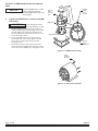
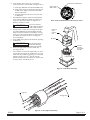
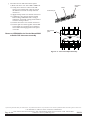
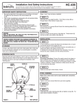
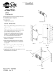
C621
Drive End (DE) or
Anti-drive End (ADE) Stator
Replacement Instructions
CAUTION
C621 alternator has a special
splice connecting the Y leads
between the ADE and DE stators
which must be handled carefully
for the stators to function properly after replacement.
The steps in this instruction sheet
replace the corresponding steps
in the CEN 600 Series Service
Manual SM6.
NOTICE
Before replacing stator, verify
that the correct replacement
stator is used. See additional
instructions provided with
stator.
Section E in CEN 600 Series Service Manual
SM6:
14. Remove ADE and DE Stators
(See Figure E-7)
a. Ensure scribe marks are visible on DE and
ADE edges of shell where tabs are missing
on DE and ADE stators.
b. Remove long nuts securing through-studs.
Remove through-studs.
c. Cut the middle of interconnect splice holding Y
leads to separate the stator connections.
d. Arrange CEN A10–132 field coil/stator tool.
e. Press DE stator out of shell.
CAUTION
f.
NOTICE
If replacing DE stator, only DE
stator should be removed.
If replacing ADE stator, both
stators should be removed.
Do not damage phase
leads when removing
stators from shell.
If replacing ADE stator, rearrange tool and
press ADE stator from shell.
Interconnect splice
First press out
DE stator
from shell
II202A
Then press out
ADE stator
from shell
Figure E–7 Removing Stators
Page 1 of 4
Section F in CEN 600 Series Service Manual
SM6:
NOTICE
2.
If replacing ADE stator or both
stators, start with step 2a.
If replacing DE stator only, start
with step 2d.
Install new ADE Stator or both new ADE/
DE Stators
CAUTION
Do not damage phase leads
when inserting stators in shell.
a. Set new ADE stator (longer phase leads face
down) on ADE edge of shell. Align scribe mark
on shell where tab is missing on ADE stator.
Arrange CEN A10–136 stator insertion tool on
stator. See Figure F–1a.
Original
scribe
mark
on shell
A10–136
stator
insertion
tool
ADE stator
Ledge inside shell
b. Press new ADE stator into position using a
spray lubricant if necessary. Make sure the
stator stops on the ledge inside the shell.
See Figure F–1a.
Missing
tab on
ADE stator
c. From the anti-drive end, insert 6 insertion
studs provided with CEN A10-136 stator insertion tool into new ADE stator. See Figure F–1b.
Figure F–1a ADE Stator Assembly
Stator
insertion
studs (6)
Figure F–1b Stator Insertion Studs
Page 2 of 4
II202A
d. Turn shell so drive end is up. To properly
position DE stator inside shell (see Figure F–1c):
1) Coil longer ADE stator leads inside ADE stator.
Scribe mark on DE of shell
Scribe mark on
ADE of shell
2) Align scribe mark on shell with missing tab
on DE stator. Align 6 insertion studs with
holes in DE stator.
3) Arrange CEN A10–136 stator insertion tool
on DE stator.
e. Press DE stator in place. Insertion studs should
enter holes in DE stator. Make sure DE stator
stops on ledge inside shell. See Figure F–1c.
Remove 6 insertion studs.
CAUTION
f.
Phase Lead and Field Coil Lead Orientation—C621
Do not use insertion
studs in place of throughstuds in final assembly.
On DE stator, remove stator wedges from openings where ADE stator leads and field coil leads
will pass between DE stator windings. See Figure F–1c for locations of DE stator phase leads
and ADE stator phase leads as arranged in
stator windings.
g. Insert ADE stator phase leads between openings
in DE stator.
A10–136
stator
insertion
tool
DE stator
Do not damage phase
leads when threading
leads through openings.
h. Insert through-studs from anti-drive end.
See Figure F–1d.
CAUTION
i.
Insertion
studs (6)–
not for final
assembly
Use locknuts to secure through-studs on drive
end of shell. See Figure F–1d. Hex flat on screwhead must be parallel to winding. Use a suitable
adhesive such as Loctite® 222 on threads.
Follow manufacturer’s instructions. Torque nuts
on drive end to 4.5 Nm/40 lb. in.
Ledge inside shell
Figure F–1c DE Stator Assembly
Long nuts
Through-stud
Figure F–1d Through-stud Assembly
II202A
Page 3 of 4
j.
Reconnect stators with interconnect splice:
1) Slide new sleeve over end of DE or ADE lead.
2) Crimp new connector socket on the DE
stator Y lead. Crimp new connector pin on
the ADE stator Y lead. Securely mate the
connectors.
Sleeve
Connector
socket
Connector pin
3) Apply hi-temp solder over mated connection.
4) Completely cover mated connection with
Dow Corning® SE 9186L RTV coating or
equivalent—wait until coating has hardened
to ensure waterproofness.
5) Position new sleeve over sealed connection.
6) Position spliced Y leads against wall of shell
so that field coil can fit into space between
stators without damaging interconnect splice
or Y leads.
Return to CEN 600 Series Service Manual SM6
to finish C621 alternator assembly
Interconnect
splice
Figure F–1e Interconnect Splice Assembly
If you have questions about your alternator or any of these instructions, or if you need to locate a Factory Authorized Service Dealer, please contact us at:
Page 4 of
C. E. Niehoff & Co.• 2021 Lee Street • Evanston, IL 60202 USA
TEL: 800.643.4633 USA and Canada • TEL: 847.866.6030 outside USA and Canada • FAX: 847.492.1242
4
E-mail us at [email protected]
II202A