1
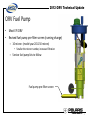
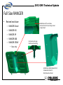
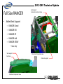
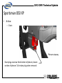
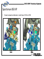
©
2012 ORV Technical Update
Welcome To The
2012 ORV Technical Update
Home page
1
©
2012 ORV Technical Update
Agenda
• ORV general information
– Fuel pump pre-filter
• Full Size RANGER
information
–
–
–
–
New model
ALL 800 models
RANGER HD
RANGER Diesel
• Mid Size RANGER
information
– RANGER EV
– RANGER 500 EFI
– RANGER 500 Crew EFI
• RZR information
–
–
–
–
–
New model
All RZR models
All 800 models
All 50” models
RZR XP
• ATV information
–
–
–
–
–
All ADC models
All Sportsman XP models
Sportsman 550 XP
Sportsman 850 XP
Classic Sportsman
• Team Tip and Service
Bulletins
2
2012 ORV Technical Update
©
ORV Fuel Pump
• Most EFI ORV
• Revised fuel pump pre-filter screen (running change)
– 10 micron (model year 2011 30 micron)
• Smaller the micron number, increased filtration
– Service fuel pump kits to follow
Fuel pump pre-filter screen
3
2012 ORV Technical Update
©
RANGER Diesel Crew
YANMAR 900 Diesel
•
•
•
•
•
•
•
•
New model added to the RANGER line up
RANGER Diesel Crew
All the Features of RANGER CREW with Diesel Power
900 Diesel Engine
90% of peak torque available at 1600 RPM
55 Amp Alternator
40% more range than the comparable gas model
Isolation mounted YANMAR diesel; low vibration
2012 RANGER Crew Diesel
4
2012 ORV Technical Update
©
Full Size RANGER
•
2012 RANGER 800 XP
What changed?
– All RANGERS
•
•
•
•
New hood latch
Revised seat base
Added center seat support
Revised heat management
2012 RANGER 800 6x6
– Reduced cab heat in the seated area
• Improved transmission serviceability
– RANGER with 800 engine
•
•
•
•
2012 RANGER 800 HD
Revised air box lid
Rotated pre-filter opening
Two wire shift switch
Revised throttle body wires and routing
– RANGER HD
• Added EBS
2012 RANGER Diesel
– RANGER Diesel
• Revised drive and driven clutch
5
2012 ORV Technical Update
©
Full Size RANGER
• Revised hood latch
• Now one piece
Pre model year 2012
– Die cast
– Will retrofit back to early models
Model year 2012
6
©
2012 ORV Technical Update
Full Size RANGER
• Revised seat base
–
–
–
–
–
RANGER Diesel
RANGER HD
RANGER XP
RANGER 6X6
RANGER CREW
Added close off to seat base
obstructs heat from entering drivers
compartment
Aluminum seat pegs
Reinforced mounting
• Rear only
Added heat shield (replaced foil)
Sandwiched material
Not featured on Diesel
7
©
Full Size RANGER
2012 ORV Technical Update
Seat Support
Fastened to cab seat base
• Added Seat Support
–
–
–
–
–
RANGER Diesel
RANGER HD
RANGER XP
RANGER 6x6
RANGER CREW
• Rear only
Seat support
Seat base
Floor rear transparent view
Cab seat support
Seat base transparent view
8
2012 ORV Technical Update
©
Full Size RANGER
•
Revised floor rear heat shield
–
–
–
–
–
–
Sandwich material
RANGER Diesel
RANGER HD
RANGER XP
RANGER 6x6
RANGER CREW
•
Rear view
Model year 2011
Model year 2012
Rear only
Sandwich heat shield in red
Heat shield
Floor back
Cut-away side view
9
2012 ORV Technical Update
©
Full Size RANGER
•
•
Floor rear
Model year 2011
Revised floor rear
Added material
– Where seat contacts floor rear
Model year 2012
Enlarged view
Additional material added to the center section of floor rear.
10
©
Full Size RANGER
2012 ORV Technical Update
Revised seat base with aluminum pegs and reinforced
mounting, more robust
• Seat and floor rear summary
Added close off
Reduces engine heat
entering drivers
compartment
Seat support provides
additional support for the seat center
Added heat shield Not featured on Diesel
Deflects heat away from seat
Revised floor rear heat shield
¾ length deflects heat away from floor back panel
Additional material added to the center section of floor back
Reduces engine compartment heat from entering drivers compartment
11
2012 ORV Technical Update
©
Full Size RANGER
•
Revised panels
– Hood liner
– Left and right wheel well panels
Radiator and fan assembly
Hood liner
Hood liner
Right wheel well panel
Heat deflector
Left wheel well panel
Front
Radiator and fan assembly
Front
Left wheel well panel
Heat deflector
top view
left side view
12
©
Full Size RANGER
2012 ORV Technical Update
Curved hood liner directs air down and
forms a seal from the cockpit
• Revised panels
• Heat deflectors
Heat deflector colored gray
13
2012 ORV Technical Update
©
Full Size RANGER
• Radiator air flow
Reduces radiator air from entering drivers compartment
through foot pedals and steering shaft openings
Front
Left wheel well panel removed
left side view
Front
Viewed with hood liner removed
top view
14
2012 ORV Technical Update
©
RANGER Gearcase
• Revised hex plug locations
• Full size
– All except 6x6 and Diesel
• Mid size
– Except EV
Fill plug
Check plug
Drain plug
15
©
2012 ORV Technical Update
Shift switch
Side X Side Shift Switch
• 2 Pin switch
– All 800 side by side
• 6 pin switch
– RANGER Diesel
2 Pin switch
Internal resistors
6 Pin switch
External resistors
16
©
2012 ORV Technical Update
RANGER 800
•
Revised engine air intake
Pre-filter box air inlet opening faces inside
right fender instead of forward
– Pre-filter
– Air box lid
• Material change for high temp
Air box lid
Integrated shield
No foil used on air box lid
17
©
2012 ORV Technical Update
RANGER 800
•
•
Throttle body wires pulled back tight and panduit secured
Starter mounted bracket secures harness
18
2012 ORV Technical Update
©
RANGER 800
•
Throttle body wires:
–
–
–
Wrapped with high temp, abrasion resistance tape
Teflon insulated wires
Revised length and routing
Panduit
Panduit behind connector
Panduit
19
©
2012 ORV Technical Update
RANGER Diesel
• Revised drive clutch
Weights and two-way bearing will not retrofit to 2011 models
Complete drive clutch will retrofit to 2011 models
Revised profile 180 gram weights
2-way idler bearing
Pin location
changed for new weights
New 92lb spring
(2011 80lb spring)
2011 weights 150 grams
Reduces shift effort and improves belt deflection
20
©
2012 ORV Technical Update
RANGER Diesel
• Revised driven clutch
2012 spacer(s) removed
21
2012 ORV Technical Update
©
RANGER HD
•
•
2012 RANGER XP and HD gearcase features revised
internal components for EBS function
EBS added-HD only
Specific gearcase
– Internal component change
– Kit-2012 RANGER XP only
•
•
•
•
No Crew
No Diesel
No 6 X 6
No pre-2012 RANGERS
Smooth one-way
EBS drive clutch
Y
N
Y
N
No offset tool. Visual adjustment only.
Refer to service manual.
Center-to-center adjustment using
Center distance tool.
Y
N
Y
N
EBS driven clutch
MBL Belt 1322898
23/66 weights
2871710
10” (25.4 cm) Center distance tool
22
2012 ORV Technical Update
©
Midsize Ranger
•
RANGER 500 EFI and Crew 500 EFI
–
Speed key accessory
•
•
same improvements as full size RANGER
RANGER EV
–
–
–
–
–
–
–
–
–
–
–
2012 RANGER 500 EFI
Revised motor controller calibration
New motor temp sensor
Revised traction battery charger
New DC to DC converter
Added a DC to DC converter relay
Revised switch 12 splice circuit
•
Redundant power supply
New contactor connector
Revised 48 volt fuse box
Added auxiliary battery relay
Revised under hood fuse box
Revised front gear box
•
•
25mph speed limit
Improved transmission serviceability (all models)
–
•
2012 RANGER 500 EFI Crew
2012 RANGER EV
2012 RANGER EV LSV
Added torsion spring
Details to follow
23
2012 ORV Technical Update
©
RANGER 500 EFI and Crew 500 EFI
•
•
•
Solenoid
Accessory Speed Key Kit 2878400
Limits vehicle to 25 mph
Kit contains
–
–
–
–
–
–
–
–
RF module
Key cap with RFID chip
Air control valve
Inline filter
Solenoid
Intake boots
Hardware
Instructions
Air control valve
Filter
ECU
Vehicle speed
sensor
Diagram
Slide
Intake boots
EFI air control valve
Similar to CV carb body
24
2012 ORV Technical Update
©
Traction battery charger and charger circuit
•
New charger
•
Revised charge indicator circuit
RANGER EV/LSV
–
–
2 Flying leads
Robust connections
–
•
Revised charging circuit
–
2011
Increased from 20 to 30 amp circuit
2 pin flying lead connector
Harness connector attached to charger shell
2012
Charger fuse
48 volt 30 amp fuse
Wire increase to match fuse
Charger fuse
48 volt 20 amp
8 pin flying lead connector
AC power cord
AC power cord
Charge indicator LED power
supplied by DC to DC converter
Supported by traction batteries
Charge indicator
LED power
supplied by
traction batteries
25
2012 ORV Technical Update
©
RANGER EV/LSV
DC to DC Converter circuit
• New converter
• Added relay
–
–
SEVCON
4 wire
–
–
48 volt side
Key activated
2011
2012
DC to DC only powered
with key on
48 V DC In
48 Volts from
key switch
Fused 48 Volt
power supply
Continuous,
48 volt power supply
12 volt power out
14.0 V DC out
26
2012 ORV Technical Update
©
2012 RANGER EV/LSV
DC to DC Relay
Contact side
48 V DC to DC to DC converter
• DC to DC Converter Relay
– 48 volt coil
– 48 volt contacts
– Location
• Mounted on DC to DC converter
bracket
Coil side
Ground (B-)
Coil side
48 V DC from
ignition switch
Contact side
48 V DC from fuse center
• Key ON
– Battery to converter relay contact
circuit closed
• Key OFF
– Opens 48 volt battery side of circuit
(No 14.0 V DC circuits)
– No power to accessory circuits
No power with key OFF
27
2012 ORV Technical Update
©
2011 RANGER EV/LSV
• 13.5 volt circuit
All accessory outlets
Charger indicator LED
Indicator fuse
DC to DC
converter
Fuse/Relay
splice
Active when key in the
ON position
Chassis fuse
Accessory fuse
Switched
power relay
Constant power
Unswitched
fuse
B + terminal under hood
NOTE: A malfunction in the DC to DC converter, chassis
fuse or switched relay could cause a motor controller fault.
Light fuse
All bulbs except:
1. Dash indicators
2. FNR switch
3. Mode switch
1.
2.
3.
4.
5.
VCM
Diagnostic plug
Speed sensor
Turf solenoid
Accessory spade terminal
13.5 V DC
Switched splice
1.
2.
3.
4.
5.
6.
Dash plug
Indicator bulbs
HR meter
FNR switch light bulbs
Mode switch light bulbs
AWD Switch
28
2012 ORV Technical Update
©
2012 RANGER EV/LSV
14.0 volt circuit
• Revised architecture
Only active when
the key is ON
Light fuse
DC to DC
converter
Chassis fuse
Accessory fuse
All bulbs except:
1. Dash indicators
2. FNR switch
3. Mode switch
Power to :
1. AWD switch
2. VCM (wake up)
3. Speed sensor
4. Accessory spade lead
5. Turf solenoid
Dc to Dc converter
14 v splice
All
accessory
outlets
To reduce motor controller faults chassis circuits are divided
into two groups.
1. DC to DC converter 14 volt splice
2. Switched 12 volt splice
All circuits shown on this slide will receive power from the
DC to DC converter.
Power to the light bulbs:
1. Forward-Neutral-Reverse switch
2. Mode switch
3. Indicator panel
Diagnostic plug
DC to DC Diode
Switched 12 volt
splice
See next slide for more information
29
2012 ORV Technical Update
©
2012 RANGER EV/LSV
14.0 volt circuit architecture revised
• Redundant power source for Switched 12 Volt Splice
Light fuse
DC to DC
converter
Chassis fuse
A redundant power source was added to support the Switched 12 Volt Splice with power.
The DC to DC diode was added to block power from traveling to the DC to DC converter
splice. A Diode / Fuse was added to both batteries to block power from entering the
batteries from the DC to DC converter. The key switch controls the Switched Power Relay.
key on power flow, key off no power.
DC to DC converter
14 v splice
Accessory fuse
Battery #7
Diode/Fuse
12 v
Only one battery is be used. The
battery with the most pressure
(voltage) will be dominant.
Battery #4
Power to the light bulbs:
1. Forward-Neutral-Reverse switch
2. Mode switch
3. Indicator panel
Diagnostic plug
Diode/Fuse
12 v
Contactor
connector
Switched
power relay
DC to DC Diode
Switched 12 volt
splice
DC to DC converter is the dominant power source. The Switched 12 Volt Splice will only
use battery power in the event there is a malfunction in the DC to DC converter circuit.
As long as the switched 12 splice is powered Motor controller faults will be reduced if DC
to DC circuit malfunctions.
30
2012 ORV Technical Update
©
2012 RANGER EV/LSV
14.0 volt circuit
Switched 12 Volt Splice - Power supply circuits comparison
Light fuse
DC to DC
converter
Normal operation
Chassis
fuse
Accessory
fuse
Dc to Dc converter
14 v splice
Normal operation / no malfunction: DC to DC converter
supplying power to switched 12 Volt Splice.
DC to DC
Diode
Switched 12
volt splice
Battery #7
Malfunction
Diode/Fuse
12 v
Contactor
connector
Battery #4
Diode/Fuse
12 v
Switched
power relay
DC to DC power source malfunction.
Redundant power supply being used
Switched 12
volt splice
One battery supplies power to switched 12 Volt Splice if DC to DC
circuit malfunctions.
31
2012 ORV Technical Update
©
2012 RANGER EV/LSV
•
Redundant power supply wiring diagram to contactor plug
–
–
Each circuit is connected to one battery in each bank (12 volts)
Each circuit contains a diode and 2 amp 12 volt fuse
Green line
Bat # 7
Blue line
Bat # 4
RED line
SHARED
•
Function / feature
–
–
Provides constant 12 V DC to LSV 2 Amp fuse circuit and Charge Indicator fuse
circuit.
Default power supply to light bulbs in: (only if DC to DC circuit malfunctions)
•
•
Forward-Neutral-Reverse switch
Mode Switch
•
•
Indicator panel
Diagnostic plug
32
2012 ORV Technical Update
©
2012 RANGER EV/LSV
Key ONContacts closed
Power to the light bulbs in the:
• Forward-Neutral-Reverse switch
• Mode switch
• Indicator panel
14.0 VDC normal
12.0 VDC if 14.0 DC to DC circuit
malfunctions
Diagnostic plug
14.0 VDC normal
12.0 VDC if 14.0 DC to DC circuit
malfunctions
If DC to DC converter circuit is functioning
this circuit will be powered by the DC to DC
converter 14.0 vdc.
•
12 volt Switch Power Relay Circuit
–
–
–
The key switch controls the Switched
Power Relay.
Key on, power flow
key off, no power
33
©
RANGER EV/LSV
•
•
Revised contactor connector
Added the Diode leads
–
–
–
Model Year 2012
Model Year 2012
7 pin
Pin C, D, E, and G are 48 volts
Pin A, B, and F are 12 volts
•
•
2012 ORV Technical Update
Constant power
48 volt fuse box 2012
–
1- 48 volt 20 amp fuse
•
–
Dash
2 - 48 volt 30 amp fuses
•
•
Traction batteries charge
DC to DC converter primary power
34
©
2012 ORV Technical Update
RANGER EV/LSV
•
•
Auxiliary battery relay circuit
Key ON
– Auxiliary relay closed. Power, 14.0 volts from the auxiliary DC to DC converter to
auxiliary batteries.
– DC to DC relay closed. Allows 48 volts to auxiliary battery DC to DC converter.
•
Key OFF
– Auxiliary relay open. Open circuit between DC to DC converter 14.0 volts, to auxiliary
batteries.
– DC to DC relay open. Open 48 volt circuit to auxiliary battery DC to DC converter.
35
©
2012 ORV Technical Update
RANGER EV/LSV
•
•
Auxiliary battery relay
Power flow
–
Key ON red line
48 vdc
AUX. DC TO DC
CHARGER
14.0 vdc
36
©
2012 ORV Technical Update
RANGER EV/LSV
•
•
Auxiliary battery relay circuit
Wiring diagram
48 Volt traction batteries
12 Volt batteries
Auxiliary battery
DC to DC charger
connector
37
2012 ORV Technical Update
©
RANGER EV/LSV
Charger fuse 48 V 5 amp
Charger fuse 14 V 15 amp
•
•
•
Fuse box changes
2011 to 2012
Increased wire to match
fuse
Model Year 2011
Unswitched fuse
Red outline indicates change
between previous model years
Spare15 amp
Added Switched Auxiliary Relay
Spare 25 amp
Revised Charger fuse 48 V 30 amp
Revised Charger fuse 14 V 25 amp
LSV fuse provides constant power
for hazard signals
Model Year 2012
Added Chassis fuse 14 v 20 amp
38
©
2012 ORV Technical Update
RANGER EV/LSV
• Front gearcase
– Torsion spring added
– No spring retainer
– Revised hub coil
• 27.1 +/- 10% ohms
1. Revised torsion spring
2. Revised roller cage
3. Revised ring gear
39
©
2012 ORV Technical Update
RANGER EV/LSV
• Ring gear detail view
Roller cage
Torsion spring
Ring gear
40
2012 ORV Technical Update
©
RZR
• What changed?
– New model
• RZR 570
– New engine
– Revised chassis
– All RZR models
• Gear selector
– 2 wire (identical to RANGER 800)
•
•
•
•
•
Removable front grille
Decreased cab water and dust intrusion
Revised passenger grab tube
Common seat belt with full size RANGER
Common master cylinder with RZR XP
– Shocks
• RZR S LE - FOX shocks
• RZR 4 and RZR XP - FOX shocks with toolless clickers
– All RZR 800
• Revised rear gearcase
• Revised drive clutch spring
– RZR 50” (127 cm)
• Revised spark arrestor
• Revised sway bar
– RZR XP
• Splice less belt
• Revised prop shaft
• Revised A-arm
– Reduced steering effort
• Revised front wheel bearing carrier
• Revised coolant surge tank and filler
neck
• Reduced water intrusion
– RZR XP International
•
•
•
•
Revised gearcase with differential
External mechanical park brake
EPS standard
Front sway bar standard
41
©
2012 ORV Technical Update
RZR 570
Features
• Trail Capable 50” Wide
• True On-Demand AWD
• 10” Ground Clearance
• 9.5” Suspension Travel
• ProStar 570 Engine
–
–
–
–
45 Horsepower
Single Cylinder 567cc
4 Valve DOHC Wet Sump
650 Watts
RZR XP Style GearCase
•
•
•
•
Helical Cut Gears
Low Friction Bearings
No Power-robbing right angle drives
Compact design
42
2012 ORV Technical Update
©
RZR 570
Engine air inlet
• RZR 570 Chassis
PVT air inlet
Similar to RZR 50”
Revised from behind the
seats to rear of vehicle
43
2012 ORV Technical Update
©
RZR 570
Similar to RZR XP
• RZR 570 Left side view
– Plastic removed
Similar to RZR 50”
Engine intake
PVT intake
RZR XP rear gearbox
RZR XP PVT cover
44
©
2012 ORV Technical Update
RZR 570
• Inspection panel removal
– Provides easy access to air filter
– New air filter design
Removal panel
Similar to RZR XP
Air box assembly
45
©
RZR 570
2012 ORV Technical Update
RZR XP style air box
• Lay out
Removable frame section
Thermostat housing hose
Water pump hose
Removable frame section
PVT air exit
By-pass hose
Large diameter
prop shaft
46
2012 ORV Technical Update
©
RZR 570
Rear mounted sway bar with rubber bushings on end links
• Rear suspension
Lower link attached
through shock bolt
– A-arm mounting
– Sway bar mounting
Revised upper and lower a-arm and mounting
Revised bearing carrier
47
©
2012 ORV Technical Update
RZR 570
• Rear A-arms
• Lube location points
Zerk fittings
Zerk fittings
48
2012 ORV Technical Update
©
RZR 570
• Fuel Supply
Fuel tank vent line (soft hose)
Fuel tank
Fuel tank shown in
transparent view
Fuel line (formed tube quick connect)
49
2012 ORV Technical Update
©
RZR 570
• Engine mounting
• PTO side view
– Through-bolt design
– Plates
Bolt A location
Bolt B location
Bolt C location
Bolt D location
A
Engine mounting bolts A-D
Plates
B
C
D
50
2012 ORV Technical Update
©
RZR 570
• Engine mounting
• Top view
– No joint
– Plates sandwich components
• Gearcase
• Engine case
PTO mounting location
Mag mounting location
Plates
Plates
51
2012 ORV Technical Update
©
RZR 570
Stator lead
Coolant by-pass fitting
• Engine layout
Coolant bleed
Revised fuel rail
CPS
T-MAP
Throttle body not illustrated
• Revised throttle body similar to 2011 800 M17 Side X Side
• IAC and TPS common with 2011 800 M17 Side X Side
CPS connector
52
2012 ORV Technical Update
©
RZR 570
• Engine layout
Stator connector
Engine temp sensor
Engine breather
Cam chain tensioner
CPS connector
53
2012 ORV Technical Update
©
RZR 570
• Engine layout
Stator connector
CPS connector
Oil Fill/Dipstick
Water pump cover
Water pump inlet
Oil filter
54
2012 ORV Technical Update
©
RZR 570
•
•
•
Top end
Dual overhead camshafts
Shim under bucket
– Shims common with RZR XP
Shim
Cut-away view
55
2012 ORV Technical Update
©
RZR 570
Exhaust camshaft
• Top end
•
Centrifugal design compression release
Compression release mechanism
Centrifugal feature
56
©
2012 ORV Technical Update
RZR 570
• Water pump
• Impeller
• Shaft and seal
Water pump shaft slotted
drive coupler
Impeller
Water pump weep outlet
Oil seal
Mag cover houses the impeller, water pump shaft, oil seal,
mechanical seal, and stator
Mechanical seal
NOTE: Mag cover removed for illustration
57
2012 ORV Technical Update
©
RZR 570
• Oil pump drive
• Cam chain guide
Counter balancer
Oil pump drive chain
Cam chain
Crankshaft (mag end)
Cam chain guide
Oil pump
58
2012 ORV Technical Update
©
RZR 570
• Engine PTO view
Piston at TDC
Counter balancer
PTO bearing
retaining plate
Oil pick up
59
©
2012 ORV Technical Update
RZR 570
• Engine Management System
– Based on 2011 RZR 800
– M 17 controller
• Ignition Switch
– 4 position
• On - Start – Lights – Off
• Headlight circuit
– Relay controlled
• Start circuit
– Start solenoid grounds through brake light switch
60
©
2012 ORV Technical Update
All RZRs
• Removable front grille
– Easy radiator access
– Snaps into place
Front grille upper tabs
Lower tabs
61
2012 ORV Technical Update
©
All RZRs*
Floor / cab seal
• Reduced cab water and dust intrusion
• Steering column boot added
• Upper seal between floor and cab added
– Similar to RZR XP
*Not on the RZR 570
Steering shaft rubber boot
Improved dash sealing to keep mud and heat off the driver
62
©
2012 ORV Technical Update
All RZRs
• Revised passenger grab tube
– Larger tube
– Bushing added
– Welded bracket
Grab tube bracket
welded to frame tubes
Will not retrofit back
Passenger grab tube now square
Anti-Rattle Passenger Grab Bar
Grab tube bushing
NOTE: Plastic removed for visual purpose
63
2012 ORV Technical Update
©
RZR Seat Belt
• Model year 2011 RZR cab frame
• Seat belt mounting location
Net mounting bracket
Seat belt bracket
Passenger side seat belt
Viewed from inside cab looking back
Viewed from inside cab
looking back
64
2012 ORV Technical Update
©
RZR Seat Belt
• Model year 2012 RZR cab frame
• Seat belt mounting location
• Common seat belt with RANGER
Passenger side seat belt
Viewed from passenger side looking into cab
Net and seat belt mounting bracket
Viewed from passenger side looking into cab
65
2012 ORV Technical Update
©
RZR
Push bar increased approximately 6
mm for 2012
• Master cylinder common with RZR XP
– RZR
– RZR S
– RZR4
Pedal closer to
operator for 2012
2011 push bar length
66
2012 ORV Technical Update
©
RZR Shocks
• Shocks
Twin Tube
Mono tube
– RZR 50” twin tube
• Revised jounce bumper
– More durable material
– RZR S Base model
• Sachs mono tube
– RZR S LE models
• Fox Podium X
Podium X
Screw adjust
– RZR 4 and RZR XP
• Podium X 2.0
• Clicker knobs
• Revised calibration
Podium X 2.0
Clicker knob
67
2012 ORV Technical Update
©
All RZR with 800 engine
• Removed O-ring seal
Oil ring removed
Oil ring seal
RZR final drive
2011 and older
68
©
2012 ORV Technical Update
All RZR 800
•
•
•
•
Revised drive clutch spring
Increased pressure
7043789 Neon Green
Will retrofit to 2011 RZR 800
69
©
2012 ORV Technical Update
RZR 50’’ (127cm)
• Spark arrestor
– Through-bolt design (similar to the RZR XP)
Spark arrestor
70
2012 ORV Technical Update
©
RZR 50” (127 cm) Sway Bar
Revised hollow tube sway bar
• Revised front sway bar 50” (127 cm 800) and 570
– Tube
– Mounting
– Links
Link with
rubber ends
P-Clamp
Revised Sway Bar
bushings
Link with upper and
lower joints
Mounts with shock
through bolt
2011 and older
2012
71
©
2012 ORV Technical Update
RZR General Clutch Changes
Revised RZR XP belt
•
•
•
•
Stronger
Splice-less
Cut edge
3211148 MBL
72
©
2012 ORV Technical Update
RZR XP
Prop Shaft
Revised prop shaft
• Rubber isolated bearing
• New bracket welded to frame
• Retrofit to 2011 RZR XP requires
the following:
–
–
–
–
Both sections of shaft
Rubber mounted bearing
Shaft support bracket
Fasteners to secure the bracket
to frame
Prop Shaft bearing
mounting bracket
Bracket mounting holes
used when retrofitting
bearing to 2011 RZR XP
73
2012 ORV Technical Update
©
RZR XP
• Revised A-arm
• Caster change
• Reduces steering effort
Front
Overlay
Black 2011
Green 2012
Trailing edge 2011
Model year 2011
Model year 2012
Trailing edge 2012
Ball joint moved back to reduced
steering effort
74
2012 ORV Technical Update
©
RZR XP
• Revised front wheel bearing carrier
• Ball joint pinch bolt increased to 10 mm o.d.
Ball joint cavity
Bearing carrier
10 mm o.d.
75
2012 ORV Technical Update
©
RZR XP
• Revised coolant surge tank
• Increased capacity
2011
2012
76
2012 ORV Technical Update
©
RZR 570 and RZR XP
• Cooling system
• Revised filler neck
• Revised radiator cap
47.8 mm
39.0 mm
56.5 mm
2011 RZR XP
43.0 mm
2012 RZR 570 and RZR XP
77
2012 ORV Technical Update
©
RZR XP
• Revised box panels
– Reduced water intrusion
– Behind the grille and the foam
– Both PVT and engine air inlet
2012 holes eliminated in panel
to reduce water intrusion
2011 holes in panel
View of left box panel
78
2012 ORV Technical Update
©
RZR XP
• Revised side panel intake foam seal
– Reduces water intrusion
Left hand side panel
Intake resonator
Intake resonator drain
Revised intake foam seal
79
2012 ORV Technical Update
©
RZR XP International
• New features
– External mechanical park brake
– Turf mode
• Differential
Turf solenoid
Park brake disc
80
2012 ORV Technical Update
©
RZR XP International
• Revised Gearcase
– Differential added
– Output shaft
Added Turf differential gear set
Output shaft revised for
park brake disc
Case revised for park brake caliper
Park brake disc
81
©
2012 ORV Technical Update
RZR XP International
• External mechanical park brake
– Lever assembly
– Caliper assembly
Park brake lever assembly mounted
between seat belt buckles
NOTE: Rubber boot removed for
illustration
Park brake disc
Park brake caliper
82
©
2012 ORV Technical Update
ATV
•
2012 Sportsman 850 XP
Discontinued models
– Outlaw
– 850 X2
•
What changed?
– All ADC models
• Added O-rings to hub clutch packs
2012 Sportsman 550 XP
– All Sportsman XP
• Revised A-arm
– Sportsman XP 550
• Added Luk Coupler (similar to Sportsman 850)
– Sportsman XP 850
• Increased power
• Revised connecting rods
2012 Sportsman 500 HO
– Classic Sportsman
• Revised front cab
– International Classic Sportsman
• New procedure for headlight adjustment
83
2012 ORV Technical Update
©
Sportsman ADC
ADC hubs
• Revised ADC hub
– O-rings added to hubs
– Separates friction plates
– Allows oil to penetrate between plates
O-rings
84
©
2012 ORV Technical Update
Sportsman XP
• Revised A-arm
• Improved bushing to tube fit
• Drawn Over Mandrel (DOM ) pivot tubes
– Controlled inner diameter tube
New process to control ID of tube
Pivot tubes
85
2012 ORV Technical Update
©
Sportsman 550
•
2011 Sportsman XP550 built after 03/01/11 and all 2012
–
–
–
Luk Coupler
Revised main gearcase
BOSS driven clutch
PA-50420
Crankshaft Coupler Holder
Application: Sportsman XP 550 units built after
03/01/11
Used to hold the crankshaft when applying
torque to the coupler nut.
Gearcase revised
BOSS driven clutch shaft
2012 ADC O-rings added
to hubs
Luk engine to gearcase coupler
86
2012 ORV Technical Update
©
Sportsman 850 XP
Revised intake runners
• Revised
–
–
–
–
Air box cover strap
Intake system
Throttle body
Cylinder head
Side covers (not shown)
• Larger air box
• Revised to fit around box
• Increased power
Revised throttle body
Revised air box
Revised valve cover
Revised cylinder head
87
©
2012 ORV Technical Update
Sportsman 850 XP
• Revised
– Throttle body and mounting
– TPS
T-MAP
Throttle body is secured to
cylinder head with 4 mounting
screws.
TPS
Changed to conform
with airbox
88
©
2012 ORV Technical Update
Sportsman 850 XP
• Cylinder head revisions
Thermostat housing change to
conform with airbox
Cooling passage revised
Pressed in bypass fitting
Revised engine coolant mounts
facing downward
89
2012 ORV Technical Update
©
Sportsman 850 XP
• Revised engine breather
– Valve cover
– Breather outlet
Hollow cavity
Revised valve cover
Drains
Valve cover transparent view
90
2012 ORV Technical Update
©
Sportsman 850
• New locations
ECU mounted in front of air box
– ECU
– IAC
IAC mounts on shifter
side of air box
Air inlet tube
Air outlet hose to throttle body
91
2012 ORV Technical Update
©
Sportsman 850 XP
• Revised
– Air box plenum
– Intake runners
Side view
Air box plenum
Intake runners
Side view: transparent plenum
92
©
2012 ORV Technical Update
Sportsman 850 XP
• Air box
– Drain
Plenum cutaway
Drain plug unscrews from bottom of plenum, lowest
section of plenum. Tail retains plug when removed.
93
2012 ORV Technical Update
©
Sportsman 850 XP
• Visual comparison between model year 2011 to 2012
2011
2012
94
2012 ORV Technical Update
©
Sportsman 850 XP
•
•
Specification changes
Connecting rod bolt torque specification
– Torque to yield bolts
– Removed paint dot
– Stamped with letter to identify color
•
New torque spec.
Bolts cannot be reused. See
service manual for specifications
RPM limit
– Model year 2011
• 8000 RPM
– Model year 2012
• 7600 RPM
•
Drive clutch weight change
– Model year 2011
• One-up utilizes 60 gram weights
• Two-up utilizes 68 gram weights
Revised connecting rod
– Model year 2012
• Common 63 gram weight between one and two up
95
©
Classic Sportsman
2012 ORV Technical Update
Front plastic /mounting
Storage location
• Revised front cab
• Under rack storage
–
–
–
–
–
Sportsman 400 HO
Sportsman 500 HO
Sportsman 800
Sportsman 500 HO Touring
Sportsman 800 6x6
Front rack/mounting
96
©
2012 ORV Technical Update
International Tractor / Forest Sportsman
• Headlight adjustment
– Headlight adjustment access plug
Remove plug to adjust headlight beam
Headlight upper access location
Headlight lower mounting
97