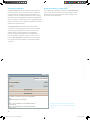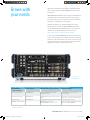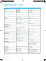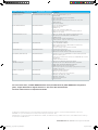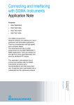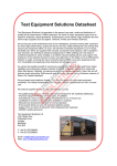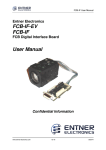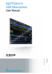
1
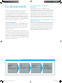
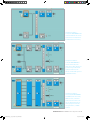
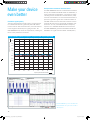
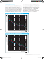
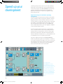
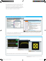
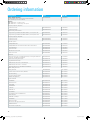
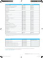
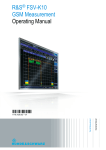
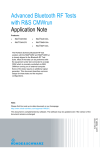
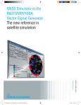
SMW200A_bro_en_3606-8037-12_v0101.indd 1 Product Brochure | 01.01 Test & Measurement R&S®SMW200A Vector Signal Generator The fine art of signal generation 27.03.2013 14:56:11 R&S®SMW200A Vector Signal Generator At a glance The R&S®SMW200A is the vector signal generator for the most demanding applications. As a result of its flexibility, performance and intuitive operation, it is a perfect tool for generating complex, digitally modulated signals of high quality. The R&S®SMW200A is the ideal generator for digitally modulated signals required for the development of new wideband communications systems, the verification of 3G and 4G base stations or in the aerospace and defense sector. The I/Q modulation bandwidth of up to 160 MHz with internal baseband satisfies fourth-generation standards (e.g. LTE-Advanced and IEEE 802.11ac), and the R&S®SMW200A is designed to meet future requirements. Its modular scalable architecture allows users to optimize the generator to their applications and to upgrade it as required. A second RF path can be added, as well as a maximum of two baseband and four fading simulator modules – without compromising on signal quality. As a result, the R&S®SMW200A can create signal scenarios that previously required multiple instruments or could not be implemented at all. From MIMO up to 8x2 to LTE-Advanced carrier aggregation including fading – never before has an instrument offered such high-class signal generation capability. If more than two RF paths are required, additional R&S®SGS100A signal generator modules can be connected. The intuitive, touchscreen-based operating concept provides the user with an overview of measurements, no matter how complex, and quickly delivers the desired results. Key facts ❙❙ One or two RF paths with frequency range from 100 kHz to 3 GHz or 6 GHz ❙❙ Up to 160 MHz I/Q modulation bandwidth (in RF) with internal baseband ❙❙ Options for all important digital communications standards ❙❙ Optional integrated fading simulator with up to 160 MHz bandwidth ❙❙ Support of all key MIMO modes including 3x3, 4x4 and 8x2 ❙❙ Intuitive operation via touchscreen with block diagram as key element 2 SMW200A_bro_en_3606-8037-12_v0101.indd 2 27.03.2013 14:56:14 R&S®SMW200A Vector Signal Generator Benefits and key features For all your needs ❙❙ Frequency range from 100 kHz to 3 GHz or 6 GHz ❙❙ Optional second RF path with 100 kHz up to 3 GHz or 6 GHz ❙❙ Versatile configuration: from single-path vector signal generator to multichannel MIMO receiver tester ❙❙ Ideal for MIMO, MSR or LTE-Advanced applications thanks to up to eight signal sources and up to 16 fading channels ❙❙ Modular architecture for optimal adaptation to the application at hand ▷▷ page 4 Simplify your setup ❙❙ Easy generation of complex signals ❙❙ Max. eight baseband generators on two internal baseband modules with realtime coder and ARB ❙❙ Internal digital adding of baseband signals, even with frequency and level offset ❙❙ Support of all important digital standards such as LTE, LTE-Advanced, 3GPP FDD/HSPA/HSPA+, GSM/EDGE/ EDGE Evolution, TD-SCDMA, CDMA2000®/1xEV-DO, WLAN IEEE 802.11a/b/g/n/ac ❙❙ No separate PC software required for digital standards ❙❙ LTE and 3GPP test case wizards for easy base station conformance testing in line with 3GPP TS 25.141 or 3GPP TS 36.141 ▷▷ page 6 Bring reality to your lab ❙❙ Optional integrated fading section for channel emulation with up to 160 MHz bandwidth ❙❙ All important fading scenarios available as presets ❙❙ Installation of up to four fading modules, providing as many as 16 ”logical“ faders ❙❙ Implementation of all key MIMO fading scenarios such as 2x2, 3x3, 4x4 and 8x2 using a single instrument ❙❙ Support of complex applications such as dual-carrier HSPA, LTE carrier aggregation and multi-user LTE SMW200A_bro_en_3606-8037-12_v0101.indd 3 ❙❙ Connection of R&S®SGS100A signal generator modules to provide up to four RF paths ❙❙ Phase coherence option, e.g. for beamforming applications ▷▷ page 8 Make your device even better ❙❙ Excellent signal quality for high accuracy in spectral and modulation measurements ❙❙ I/Q modulator with up to 2 GHz RF modulation bandwidth ❙❙ 160 MHz I/Q modulation bandwidth (in RF) with internal baseband ❙❙ Exceptional modulation quality, e.g. –49 dB EVM (meas.) with 160 MHz wide WLAN IEEE 802.11ac signals ❙❙ High-end pulse modulation with on/off ratio > 80 dB and rise/fall time < 10 ns ❙❙ Excellent spectral purity (SSB phase noise –139 dBc (typ.) at 1 GHz, 20 kHz offset) ▷▷ page 10 Speed up your development ❙❙ Intuitive operating concept and clever help functions for quick success ❙❙ Block diagram as key operating element to visualize signal flow ❙❙ Adaptive GUI for overview of both simple and complex scenarios ❙❙ Graphical signal monitoring at practically every point in the signal flow ❙❙ Context-sensitive online help system with complete user documentation ❙❙ SCPI macro recorder and code generator for generating executable remote control code from manual operating steps (for MATLAB®, CVI, etc.) ▷▷ page 12 Grows with your needs ❙❙ Customizing of instrument to accommodate virtually every application ❙❙ Advanced plug-in system for retrofitting baseband modules without instrument recalibration ❙❙ Software upgrades possible at any time, simple and quick activation via key codes ❙❙ Firmware updates – keeping pace with the latest developments ▷▷ page 15 Rohde & Schwarz R&S®SMW200A Vector Signal Generator 3 27.03.2013 14:56:14 For all your needs Advanced RF measuring equipment must, above all, be flexible. Performance and functionality requirements vary depending on test setup and application. The R&S®SMW200A is unrivaled in mastering this challenge and sets new standards for signal generators. In development and verification, for any type of DUT (components, modules, complete base stations) – the R&S®SMW200A always generates the appropriate test signals. Versatile configuration Thanks to its modular design, the R&S®SMW200A can be equipped with the exact options required for a specific application. Any configuration is possible, from a c lassic single-path vector signal generator to a multichannel MIMO receiver tester. Ideal for MIMO, MSR or LTE-Advanced applications And that is by far not all. The capabilities of the R&S®SMW200A surpass those of two conventional generators combined. When the instrument is fully equipped, the baseband section provides up to eight independent signal sources and up to 16 logical faders. This makes the R&S®SMW200A ideal for MIMO and other complex applications encountered in LTE‑Advanced (carrier aggregation), HSPA (dual carrier) and multistandard radio, etc. Modular architecture for optimal adaptation to the application at hand Almost all options of the R&S®SMW200A can be retrofitted, most of them simply via key code. Starting from the basic configuration as a classic single-path vector signal generator, the R&S®SMW200A can be customized as required for any application. Users only have to purchase what they currently need and are free to decide on upgrades according to their future requirements. The generator can be equipped with a maximum of two internal baseband modules and four fading simulator modules. It is also possible to install a second 3 GHz or 6 GHz RF path. This concept yields two full-featured vector signal generators in a single unit, so that even complex signal scenarios (e.g. wanted signal + interferer, dual cell, TX/RX diversity) can be created easily. Basic R&S®SMW200A architecture Baseband signal generation (digital) up to two hardware modules, up to eight signal sources Fading (digital) up to four hardware modules, up to 16 logical faders Signal routing, AWGN D/A conversion I/Q modulation RF signal generation one or two paths internally, one or two additional paths via external ¸SGS100A 4 SMW200A_bro_en_3606-8037-12_v0101.indd 4 27.03.2013 14:56:14 Configuration example 1: A single-path R&S®SMW200A with internal baseband can be used for measurements on components or for fundamental receiver testing. Configuration example 2: A two-path R&S®SMW200A is ideal for receiver and performance tests on base stations. One generator can generate w anted signal plus interferer (in this example, a wanted LTE signal and a 3GPP FDD interferer). Configuration example 3: A fully equipped R&S®SMW200A with MIMO option covers all key MIMO scenarios, such as 8x2 shown in the screenshot. In this case, the baseband section provides eight signal sources and 16 “logical” f aders, i.e. MIMO channels. SMW200A_bro_en_3606-8037-12_v0101.indd 5 Rohde & Schwarz R&S®SMW200A Vector Signal Generator 5 27.03.2013 14:56:16 Simplify your setup Easy generation of complex signals A vector signal generator needs a powerful baseband section to meet the requirements of advanced communications systems. The R&S®SMW200A sets standards in this field too. Each of the two available baseband modules contains a realtime coder and an arbitrary waveform generator with max. 1 Gsample memory depth. The bandwidth of up to 160 MHz covers modern digital standards, such as LTE‑Advanced and WLAN IEEE 802.11ac, as well as wideband multicarrier or multistandard radio signals. Support of all important digital standards The R&S®SMW200A uses software options to generate signals for all important digital standards, particularly LTE/LTE‑Advanced, 3GPP FDD/HSPA/HSPA+, GSM/EDGE/ EDGE Evolution, TD‑SCDMA and WLAN IEEE 802.11a/b/ g/n/ac. The entire physical layer is simulated, as well as channel coding for the majority of standards. As a result, the R&S®SMW200A is perfect for standard-compliant receiver measurements, e.g. tests on base stations in line with 3GPP TS 25.141 (for 3GPP FDD) or 3GPP TS 36.141 (for LTE/LTE-Advanced). The baseband signals can be digitally added, provided with a frequency offset of max. ±80 MHz and varied in power and phase relative to each other. This makes it incredibly simple to generate multicarrier scenarios and combinations of different digital standards with the R&S®SMW200A. In contrast to many other solutions on the market, the signals for the digital standards can be configured and generated directly on the R&S®SMW200A. Because the software options integrate seamlessly into the instrument’s firmware, there is no need for additional PC software. This simplifies operation and also saves valuable testing time, since no time-consuming waveform transfer from the external PC software to the signal generator's output memory has to be performed. A single two-path R&S®SMW200A is all that is needed to create the wanted signal plus interferer scenarios often required in receiver testing. Depending on the scenario's overall bandwidth and the desired level difference between wanted signal and interferer, the signals can in many cases be output by using only one RF path. The second RF path is available for other tasks, e.g. generation of an additional CW interferer. As a result of its outstanding performance, the R&S®SMW200A responds virtually without delay to new settings, even when they require comprehensive signal calculations. Therefore, test scenarios can easily and quickly be adapted to new requirements. Parameters can be varied with immediate effect for optimization or troubleshooting, without causing unproductive interruptions or waiting time. Users benefit from numerous help functions. Predefined settings can be used to configure standard-compliant signals (e.g. test models defined in the standard) at the press of a button. Two-path R&S®SMW200A In a two-path R&S®SMW200A, baseband signals can be digitally added and provided with baseband frequency offset. This makes it possible to easily generate multicarrier scenarios or wanted signal plus interferer scenarios. 6 SMW200A_bro_en_3606-8037-12_v0101.indd 6 27.03.2013 14:56:16 Visual aids such as the time plan in the LTE option provide a graphical overview of the signal structure. They help users keep track of even complex signal scenarios and quickly set the desired parameters. The test case wizards for complex digital standards such as LTE and 3GPP FDD (UMTS) are powerful tools that simplify the user's task. It only takes a few steps to configure the R&S®SMW200A for base station tests in line with 3GPP TS 36.141 or 3GPP TS 25.141. Internal triggering between the different baseband modules ensures internal signal generation with 100 % synchronicity. Complicated cabling of multiple instruments is no longer necessary. For synchronization with the DUT the R&S®SMW200A has three front panel BNC connectors that can be assigned user-specific control signals as desired. This gives users easy access to any trigger, marker and clock signals they require. The rear panel of the R&S®SMW200A offers another three connectors for user-specific signals and three connectors per baseband module for additional control signals. In many cases, conclusive measurements are only possible with correctly timed signals. This is why it is crucial for most measuring applications to synchronize measuring instruments and DUT using, for example, a frame trigger. The R&S®SMW200A meets virtually all requirements. Time plan display in the LTE option of the R&S®SMW200A. The LTE test case wizard allows the R&S®SMW200A to be conveniently and cleverly configured for BTS tests in line with 3GPP TS 36.141. In this example, wanted signal and interferer for a narrowband blocking test are set. SMW200A_bro_en_3606-8037-12_v0101.indd 7 Rohde & Schwarz R&S®SMW200A Vector Signal Generator 7 27.03.2013 14:56:17 Bring reality to your lab Advanced, state-of-the-art channel emulation The internal fading simulator option is another element that distinguishes the R&S®SMW200A from other RF vector signal generators. Using latest FPGA technology the hardware was designed for exceptional compactness so that up to four of the powerful fading modules can be installed. These modules can simultaneously emulate as many as 16 fading channels. The maximum fading bandwidth is 160 MHz. As a result, the R&S®SMW200A can realistically map even higher-order MIMO scenarios such as 3x3 MIMO for WLAN IEEE 802.11. Inside buildings, there are more reflections than in open terrain. The time difference between different echos normally is in the range of only a few nanoseconds. Its time resolution of 2.5 ps and its ability to simulate up to 20 paths per fading channels enable the R&S®SMW200A to realistically simulate indoor fading scenarios. All in all, the R&S®SMW200A offers a fading performance that has so far only been achieved by significantly more expensive special instruments (e.g. RF faders). The user can select the fading scenarios required for all major standards directly from the predefined settings. In addition to classic multipath scenarios with Raleigh, Rice or pure Doppler fading, the R&S®SMW200A can also simulate the dynamic scenarios specified in recent standards, such as birth-death, moving propagation and high-speed train. All parameters can also be set manually, which makes it easy to implement user-specific fading configurations. Prestigious discipline: MIMO All modern wireless communications standards utilize MIMO technology to increase the effective data throughput. A test generator must be able to simulate MIMO scenarios exactly as they are present at the receive antennas of a receiver – even with complex MIMO receivers. This is where the multipath and fading capabilities of the R&S®SMW200A come into their own. The built-in baseband modules allow the simultaneous generation of up to eight signals. For MIMO scenarios, the signals from all transmit antennas – with antenna-specific coding – can be directly generated in a single instrument. In addition, the R&S®SMW200A is able to simulate the entire MIMO channel. Up to 16 logical faders cover all key MIMO scenarios such as 3x3, 4x4 and 8x2. The user can also set the correlations between the propagation paths. Multistandard setups, such as 2x2 MIMO for LTE and 3GPP FDD HSPA, are possible as well. No matter how complicated the application – the R&S®SMW200A handles unique stimulus generation and channel simulation in parallel. The R&S®SMW200A can be equipped with one or two RF paths up to 3 GHz or 6 GHz. If necessary, more RF paths can be added: Two additional I/Q-modulated R&S®SGS100A signal generator modules turn the R&S®SMW200A into an extremely compact 4x4 MIMO complete solution. The additional hardware is operated and remotely controlled directly from the R&S®SMW200A. Both the R&S®SMW200A and the R&S®SGS100A offer a phase coherence option for phase-locked coupling of multiple RF paths, e.g. for beamforming applications. The fading settings of the R&S®SMW200A can be visualized to support the user. The screenshot shows the fading path configuration of an LTE ETU300 scenario. 8 SMW200A_bro_en_3606-8037-12_v0101.indd 8 27.03.2013 14:56:18 The R&S®SMW200A easily handles even complex MIMO setups. The global system configuration dialog can be used to reconfigure the signal generator according to the required signal scenario. The block diagram on the GUI changes with the application so that the user can see at a glance which signal scenario is being generated. Every system configuration is accompanied by typical application examples. Users who “think beyond the standard” will also easily find an optimal scenario for their needs. As an alternative, the signals can be set individually in the R&S®SMW200A (separate sources mode). This mode allows the simultaneous generation of signals for different standards, which makes the R&S®SMW200A ideal for testing multistandard base stations. Combinations (e.g. LTE, WCDMA and GSM) are possible as well as the use of userdefined ARB signals. In the case of MIMO-capable standards such as LTE or WLAN, the transmit signals depend on each other. Therefore, the R&S®SMW200A features a shared menu (coupled sources mode) with which multi-antenna signals can be configured quickly and conveniently. Block diagram of the R&S®SMW200A configured for the simultaneous generation of dual cell HSPA and 2x2 MIMO for LTE with correlated fading channels. 4x4 MIMO setup - Analog I/Q output RF path A B RF path C D 4x4 MIMO setup, consisting of a two-path R&S®SMW200A and two R&S®SGS100A signal generator modules operated from the R&S®SMW200A. The modules provide RF paths 3 and 4. The R&S®SMW200A fully performs baseband signal generation and fading. SMW200A_bro_en_3606-8037-12_v0101.indd 9 Rohde & Schwarz R&S®SMW200A Vector Signal Generator 9 27.03.2013 14:56:19 Make your device even better Exceptional modulation characteristics The R&S®SMW200A features a wideband I/Q modulator with up to 2 GHz RF bandwidth. With this bandwidth, it covers practically all applications in its frequency range, including wireless and satellite communications, radar, research and education. The internal baseband makes it possible to generate signals with a maximum width of 160 MHz. State-of-the-art 16-bit D/A converters and an excellent RF chain ensure exceptional modulation characteristics. All in all, a 0.05 dB modulation frequency response over 160 MHz bandwidth can be achieved. The R&S®SMW200A generates 160 MHz wide WLAN IEEE 802.11ac signals with an EVM of –49 dB (meas.). Excellent signal quality Testing high-performance DUTs requires a signal generator solution that features significantly better RF characteristics than the DUT itself. Otherwise, the measurement results might be falsified by the signal generator. The R&S®SMW200A fully meets this requirement, enabling the DUT's entire potential to be utilized. Measured I/Q modulation frequency response with internal baseband Frequency response in dB 0.25 1900 MHz 2140 MHz 850 MHz 0.20 0.15 0.10 0.05 0 –0.05 –0.10 –0.15 –0.20 –0.25 –80 –60 –40 –20 0 20 40 60 80 Frequency offset from carrier in MHz The R&S®SMW200A generates 160 MHz wide WLAN IEEE 802.11ac signals with an EVM of –49 dB (meas.). 10 SMW200A_bro_en_3606-8037-12_v0101.indd 10 27.03.2013 14:56:19 Very good RF characteristics The RF characteristics of the R&S®SMW200A are simply impressive. The absolute level accuracy is better than 0.5 dB (f ≤ 3 GHz) across the entire specified level range from –120 dBm to +18 dBm, without additional options being required. Frequency and level setting times of 600 µs (typ.) via IEC/IEEE bus make the R&S®SMW200A the fastest high-end vector signal generator on the market and help save valuable time. Thanks to its e xcellent pulse modulator with on/off ratio > 80 dB and rise/fall time < 10 ns, the R&S®SMW200A is ideal for generating pulsed signals for radar applications. The high-end synthesizer, which is included in the standard version of the R&S®SMW200A, already delivers exceptional SSB phase noise and nonharmonics values. The R&S®SMW-B22 option improves performance even more. The R&S®SMW200A is therefore perfect for measurements that place high requirements on spectral purity. Measured SSB phase noise with R&S®SMW-B22 option –30 SSB phase noise in dBc (1 Hz) –40 100 MHz 1 GHz 3 GHz 6 GHz –50 –60 –70 –80 –90 –100 –110 –120 –130 –140 –150 –160 –170 –180 1 10 100 1k 10k 100k 1M 10M Offset frequency in Hz Measured SSB phase noise, standard performance –30 SSB phase noise in dBc (1 Hz) –40 100 MHz 1 GHz 3 GHz 6 GHz –50 –60 –70 –80 –90 –100 –110 –120 –130 –140 –150 –160 –170 –180 1 10 100 1k 10k 100k 1M 10M Offset frequency in Hz SMW200A_bro_en_3606-8037-12_v0101.indd 11 Rohde & Schwarz R&S®SMW200A Vector Signal Generator 11 27.03.2013 14:56:20 Speed up your development Increasing cost pressure results in ever shorter development cycles. At the same time, testing requirements become more stringent. The R&S®SMW200A accomplishes complex measurement tasks quickly and efficiently. Numerous innovations in intuitive user guidance make work extremely easy. Ergonomic design for maximum operating convenience A high-resolution touchscreen and an easy-to-use graphical user interface make for ergonomic operation. A block diagram provides a clear overview at all times. The user sees at a glance the signal flow and the status of all inputs and outputs. The drag & drop functionality makes signal flow reconfiguration simpler than ever. For MIMO and other complex applications, the block diagram is adapted to the prevailing signal scenario. All menus feature tabs for fast access to signal parameters. A context-sensitive online help system provides information about every parameter, such as setting range, detailed circuit description and SCPI command. Various functions facilitate everyday work, e.g. each parameter can be individually reset to its specific preset status. The built-in graphics function of the R&S®SMW200A allows the generated signals to be displayed in realtime in up to eight simultaneous windows. The user can select the type of display (I and Q versus time, frequency s pectrum, vector diagram, etc.) and the point in the signal flow where the measurement will be performed. User interface of the R&S®SMW200A. The header shows the frequency, level and important instrument statuses. The footer provides quick access to open menus. The generated signals and the measurement results of any connected R&S®NRP-Zxx power sensor(s) can be displayed as well (second field from left in footer). 12 SMW200A_bro_en_3606-8037-12_v0101.indd 12 27.03.2013 14:56:21 The baseband measurement function allows realtime measurement of the level of a signal or signal component at defined points in the signal flow. This feature is especially useful when the level of specific components of a complex signal is to be determined or varied during a measurement, as for example in closed-loop scenarios. Context-sensitive online help system of the R&S®SMW200A The sophisticated help system of the R&S®SMW200A offers useful additional functions for every parameter, e.g. a specific preset or the associated SCPI command. The online help provides more detailed information (excerpt at right). Graphical signal monitoring in realtime Graphical signal monitoring in realtime is extremely useful when it comes to generating complex signals. SMW200A_bro_en_3606-8037-12_v0101.indd 13 Rohde & Schwarz R&S®SMW200A Vector Signal Generator 13 27.03.2013 14:56:21 Automation made easy A fast instrument for speedy work The R&S®SMW200A can be controlled via all common remote interfaces. The user benefits from a number of help functions when programming an automatic test sequence control. The SCPI commands for every setting parameter can be displayed directly and all modifications of the instrument's preset status can be highlighted graphically. This makes it easy to identify all parameters that are important for remote control. The LINUX-based operating system of the R&S®SMW200A helps ensure short boot times. The high computer performance speeds up work even when settings require comprehensive signal calculation. The R&S®SMW200A also has a built-in SCPI macro recorder with code generator, which records all manual operating steps to generate a file with a remote command sequence. Code templates are provided for directly generating executable code for MATLAB® or CVI. User-specific templates can also be used. As a result, the R&S®SMW200A contributes to minimizing the time required for test automation, saving development resources. The built-in SCPI macro recorder and code generator supports fast, convenient generation of SCPI program sequences. 14 SMW200A_bro_en_3606-8037-12_v0101.indd 14 27.03.2013 14:56:22 Grows with your needs Advanced technology and a modular, upgradeable hardware concept make the R&S®SMW200A a future-ready investment. R&S®SMW200A hardware options can be retrofitted with minimum effort. The baseband modules come as plugins and can easily be inserted into the rear panel without opening or recalibrating the instrument. Software functions (e.g. digital standards) are simply activated via key codes. The R&S®SMW200A firmware can be updated from a USB flash drive or via LAN. Free updates can be downloaded from the Internet at www.rohde-schwarz.com/product/smw200a. In this way, the R&S®SMW200A can be precisely customized to suit the applications at hand and can be enhanced whenever new requirements arise. Users only have to purchase what they currently need and are free to decide on upgrades according to future requirements. Rear panel of the R&S®SMW200A. The R&S®SMW200A can be used together with many other Rohde & Schwarz instruments 1) R&S®SMW200A function/connection Related option(s) Rohde & Schwarz partner instrument Application example Digital baseband input R&S®SMW-B10 e.g. R&S®CMW500 wideband radiocommunication tester R&S®CMW500 as external I/Q source, e.g. for signaling 1) Digital baseband output R&S®SMW-K18 e.g. R&S®EX-IQ-Box digital signal interface module outputs digital baseband signals in different formats, e.g. in line with the CPRI standard Analog I/Q output R&S®SMW-K16 e.g. R&S®SGS100A signal generator module provides additional RF paths R&S®NRP sensor connector – R&S®NRP-Zxx power sensors, R&S®NRP-Z28/98 level control sensors high-accuracy power measurement, result display on the R&S®SMW200A Function in preparation. Rohde & Schwarz R&S®SMW200A Vector Signal Generator 15 SMW200A_bro_en_3606-8037-12_v0101.indd 15 27.03.2013 14:56:30 Specifications in brief Specifications in brief Frequency Frequency range, RF path A R&S®SMW-B103 100 kHz to 3 GHz R&S®SMW-B106 100 kHz to 6 GHz R&S®SMW-B203 100 kHz to 3 GHz R&S®SMW-B206 100 kHz to 6 GHz SCPI mode < 1.2 ms, 600 µs (typ.) Specified level range 3 MHz ≤ f < 6 GHz –120 dBm to +18 dBm (PEP) Setting time SCPI mode < 1 ms, 600 µs (typ.) Harmonics level < 10 dBm, CW < –30 dBc Nonharmonics CW or vector modulation with full-scale DC input, level > –10 dBm, carrier offset > 10 kHz, 200 MHz < f ≤ 1500 MHz standard < –80 dBc SSB phase noise CW, carrier offset = 20 kHz, f = 1 GHz Frequency range, RF path B (optional) Setting time Level Spectral purity with R&S®SMW-B22 option < –90 dBc standard < –131 dBc, –135 dBc (typ.) with R&S®SMW-B22 option < –136 dBc, –139 dBc (typ.) Analog modulation Supported analog modulation modes AM, FM (optional), φM (optional), pulse (optional) I/Q modulation RF modulation bandwidth Modulation frequency response in specified RF modulation bandwidth Baseband generator Signal bandwidth with external I/Q, “I/Q wideband” on 1 MHz ≤ f ≤ 4 GHz ±25 % of carrier frequency f > 4 GHz ±1 GHz with internal baseband, “I/Q wideband” on, f ≥ 320 MHz with internal baseband, “I/Q wideband” on ±80 MHz < 1.0 dB, < 0.3 dB (meas.) R&S®SMW-B10 option, up to two baseband generators can be installed standard 120 MHz with R&S®SMW-K522 option 160 MHz standard 64 Msample with R&S®SMW-K511 option 512 Msample with R&S®SMW-K511 and -K512 options 1 Gsample Sample resolution equivalent to D/A converter 16 bit Frequency offset standard –60 MHz to +60 MHz with R&S®SMW-K522 option –80 MHz to +80 MHz ARB memory depth Digital standards Supported standards and modulation systems LTE/LTE-Advanced, 3GPP FDD/HSPA/HSPA+, GSM/EDGE/EDGE Evolution, CDMA2000®, 1xEV-DO Rev. A/B, TD-SCDMA, WLAN IEEE 802.11a/b/g/n/ac, AWGN and more Fading and MIMO Fading simulator R&S®SMW-B14 option, up to four fading modules can be installed Fading bandwidth max. 160 MHz Fading channels depending on options max. 16 MIMO fading scenarios depending on options 2x2, 4x2, 2x4, 3x3, 4x4, 8x2 and more Fading modes depending on options Fading profiles depending on options multipath, moving delay, birth-death, high-speed train, two-channel interferer Rayleigh, Rice, pure Doppler, static path, Gaussian and more 16 SMW200A_bro_en_3606-8037-12_v0101.indd 16 27.03.2013 14:56:30 Options for digital communications standards (selection) Standard/technology Options Key features LTE/LTE-Advanced R&S®SMW-K55/-K69/-K81/-K84/-K85 3GPP FDD/HSPA/HSPA+ R&S®SMW-K42/-K83 GSM/EDGE/EDGE Evolution R&S®SMW-K40/-K41 CDMA2000® R&S®SMW-K46 1xEV-DO Rev. A, B R&S®SMW-K47/-K87 TD-SCDMA (3GPP TDD LCR) R&S®SMW-K50/-K51 WLAN IEEE 802.11a/b/g/n/ac R&S®SMW-K54/-K86 WiMAX™ IEEE 802.16 R&S®SMW-K49 Bluetooth® R&S®SMW-K60 ❙❙ In line with 3GPP LTE Rel. 8, 9 , 10 ❙❙ FDD and TDD ❙❙ Downlink (OFDMA) and uplink (SC-FDMA) ❙❙ Carrier aggregation ❙❙ Support of uplink closed-loop base station tests in line with 3GPP TS 36.141 ❙❙ LTE test case wizard ❙❙ In line with 3GPP FDD Rel. 11 ❙❙ Downlink and uplink ❙❙ HSDPA H-sets ❙❙ Higher-order modulation, MIMO, CPC ❙❙ Support of base station tests in line with 3GPP TS 25.141 ❙❙ 3GPP test case wizard ❙❙ MSK, FSK, AQPSK, 8PSK, 16QAM and 32QAM modulation ❙❙ Mixed frames with GSM, EDGE and EGPRS2 slots ❙❙ VAMOS support ❙❙ Support of higher symbol rates (325 kHz) ❙❙ “Framed double” sequence mode for generating realistic test scenarios with changing frame content ❙❙ In line with 3GPP2 C.S0002-C ❙❙ Radio configurations RC1 to RC5 and RC10 in forward link, RC1 to RC4 in reverse link ❙❙ All channel coding modes included in IS-2000 ❙❙ Forward link and reverse link ❙❙ Physical layer subtypes 0 & 1, 2 or 3 ❙❙ Multicarrier scenarios with up to 16 concurrent channels ❙❙ Simulation of up to four TD-SCDMA cells with variable uplink and downlink switching point ❙❙ Fixed reference measurement channels up to RMC 384 kbps in uplink and downlink ❙❙ HSDPA and HSUPA channels ❙❙ Support of all mandatory physical layer modes ❙❙ VHT frames with up to 160 MHz transmission bandwidth ❙❙ BPSK, QPSK, 16QAM and 256QAM modulation ❙❙ MIMO modes with four transmit antennas ❙❙ Frame block sequencer for alternating legacy frames in line with (11a/b/g), 11n or 11ac ❙❙ OFDM and OFDMA modulation ❙❙ Multiple zones and segments ❙❙ Space time coding for up to four antennas ❙❙ Bluetooth® 4.0, basic rate + EDR ❙❙ Bluetooth® low energy ❙❙ Support of all packet types ❙❙ Dirty transmitter For more information, see R&S®SMW200A data sheet (PD 3606.8037.22), R&S®SMW200A configuration guide, “Digital Standards for Signal Generators” data sheet (PD 5213.9434.22) and www.rohde-schwarz.com/product/smw200a. The Bluetooth® word mark and logos are registered trademarks owned by Bluetooth SIG, Inc. and any use of such marks by Rohde & Schwarz is under license. CDMA2000® is a registered trademark of the Telecommunications Industry Association (TIA - USA). “WiMAX Forum” is a registered trademark of the WiMAX Forum. “WiMAX”, the WiMAX Forum logo, “WiMAX Forum Certified”, and the WiMAX Forum Certified logo are trademarks of the WiMAX Forum. SMW200A_bro_en_3606-8037-12_v0101.indd 17 Rohde & Schwarz R&S®SMW200A Vector Signal Generator 17 27.03.2013 14:56:30 Ordering information Designation Type Order No. Vector Signal Generator 1) including power cable, quick start guide and CD-ROM (with operating and service manual) Options R&S®SMW-Bxxx = hardware option R&S®SMW-Kxxx = software/key code option Frequency Options, RF path A R&S®SMW200A 1412.0000.02 100 kHz to 3 GHz R&S®SMW-B103 1413.0004.02 100 kHz to 6 GHz R&S®SMW-B106 1413.0104.02 Signal Routing and Baseband Main Module, one I/Q path to RF R&S®SMW-B13 1413.2807.02 Signal Routing and Baseband Main Module, two I/Q paths to RF R&S®SMW-B13T 1413.3003.02 100 kHz to 3 GHz R&S®SMW-B203 1413.0804.02 100 kHz to 6 GHz R&S®SMW-B206 1413.0904.02 FM/φM Modulator R&S®SMW-B20 1413.1600.02 FM/φM Modulator and Enhanced Phase Noise Performance R&S®SMW-B22 1413.2207.02 Pulse Modulator R&S®SMW-K22 1413.3249.02 Pulse Generator R&S®SMW-K23 1413.3284.02 Multifunction Generator R&S®SMW-K24 1413.3332.02 Phase Coherence R&S®SMW-B90 1413.5841.02 Baseband Generator with ARB (64 Msample) and Digital Modulation (realtime), 120 MHz RF bandwidth Differential Analog I/Q Outputs R&S®SMW-B10 1413.1200.02 R&S®SMW-K16 1413.3384.02 Digital Baseband Output R&S®SMW-K18 1413.3432.02 ARB Memory Extension to 512 Msample R&S®SMW-K511 1413.6860.02 ARB Memory Extension to 1 Gsample R&S®SMW-K512 1413.6919.02 Baseband Extension to 160 MHz RF bandwidth R&S®SMW-K522 1413.6960.02 Signal routing main modules Frequency Options, RF path B Other RF options Baseband MIMO, fading and noise Fading Simulator R&S®SMW-B14 1413.1500.02 Additive White Gaussian Noise (AWGN) R&S®SMW-K62 1413.3484.02 Dynamic Fading R&S®SMW-K71 1413.3532.02 Enhanced Fading Models R&S®SMW-K72 1413.3584.02 MIMO Fading/Routing R&S®SMW-K74 1413.3632.02 GSM/EDGE R&S®SMW-K40 1413.3684.02 EDGE Evolution R&S®SMW-K41 1413.3732.02 3GPP FDD R&S®SMW-K42 1413.3784.02 CDMA2000® R&S®SMW-K46 1413.3884.02 1xEV-DO R&S®SMW-K47 1413.3932.02 IEEE 802.16 R&S®SMW-K49 1413.3984.02 TD-SCDMA R&S®SMW-K50 1413.4039.02 TD-SCDMA Enhanced BS/MS Tests R&S®SMW-K51 1413.4080.02 DVB-H/DVB-T R&S®SMW-K52 1413.6090.02 IEEE 802.11 (a/b/g/n) R&S®SMW-K54 1413.4139.02 EUTRA/LTE R&S®SMW-K55 1413.4180.02 Bluetooth® EDR R&S®SMW-K60 1413.4239.02 Multicarrier CW Signal Generation R&S®SMW-K61 1413.4280.02 TETRA Release 2 R&S®SMW-K68 1413.4439.02 LTE Closed-Loop BS Test R&S®SMW-K69 1413.4480.02 Digital standards 18 SMW200A_bro_en_3606-8037-12_v0101.indd 18 27.03.2013 14:56:30 Designation Type Order No. LTE Log File Generation R&S®SMW-K81 1413.4539.02 3GPP FDD HSPA/HSPA+, Enhanced BS/MS Tests R&S®SMW-K83 1413.4580.02 EUTRA/LTE Release 9 and Enhanced Features R&S®SMW-K84 1413.5435.02 EUTRA/LTE Release 10 (LTE-Advanced) R&S®SMW-K85 1413.5487.02 IEEE 802.11ac R&S®SMW-K86 1413.5635.02 1xEV-DO Rev. B R&S®SMW-K87 1413.6519.02 GSM/EDGE R&S®SMW-K240 1413.4739.02 EDGE Evolution R&S®SMW-K241 1413.4780.02 3GPP FDD R&S®SMW-K242 1413.4839.02 GPS R&S®SMW-K244 1413.4880.02 CDMA2000® inkl. 1xEV-DV R&S®SMW-K246 1413.4939.02 1xEV-DO R&S®SMW-K247 1413.4980.02 IEEE 802.16 R&S®SMW-K249 1413.5035.02 TD-SCDMA R&S®SMW-K250 1413.5087.02 TD-SCDMA Enhanced BS/MS Tests R&S®SMW-K251 1413.5135.02 DVB-H/DVB-T R&S®SMW-K252 1413.6190.02 DAB/T-DMB R&S®SMW-K253 1413.6248.02 IEEE 802.11n R&S®SMW-K254 1413.5187.02 EUTRA/LTE R&S®SMW-K255 1413.5235.02 Bluetooth® EDR R&S®SMW-K260 1413.5287.02 Multicarrier CW Signal Generation R&S®SMW-K261 1413.5335.02 Additive White Gaussian Noise (AWGN) R&S®SMW-K262 1413.6460.02 TETRA Release 2 R&S®SMW-K268 1413.5387.02 3GPP FDD HSPA/HSPA+, Enhanced BS/MS Tests R&S®SMW-K283 1413.6290.02 EUTRA/LTE Release 9 and Enhanced Features R&S®SMW-K284 1413.5535.02 EUTRA/LTE Release 10 (LTE-Advanced) R&S®SMW-K285 1413.5587.02 IEEE 802.11ac R&S®SMW-K286 1413.5687.02 1xEV-DO Rev. B R&S®SMW-K287 1413.6560.02 NFC A/B/F R&S®SMW-K289 1413.6654.02 19" Rack Adapter R&S®ZZA-KN4 1175.3033.00 Keyboard with USB Interface (US assignment) R&S®PSL-Z2 1157.6870.04 Digital standards using R&S®WinIQSIM2™ 2) Recommended extras The base unit can only be ordered with an R&S®SMW-B10x frequency option and an R&S®SMW-B13 or R&S®SMW-B13T signal routing and baseband main module. R&S®WinIQSIM2™ requires an external PC. 1) 2) Service options Extended Warranty, one year R&S®WE1SMW200A Extended Warranty, two years R&S®WE2SMW200A Extended Warranty, three years R&S®WE3SMW200A Extended Warranty, four years R&S®WE4SMW200A Extended Warranty with Calibration Coverage, one year R&S®CW1SMW200A Extended Warranty with Calibration Coverage, two years R&S®CW2SMW200A Extended Warranty with Calibration Coverage, three years R&S®CW3SMW200A Extended Warranty with Calibration Coverage, four years R&S®CW4SMW200A Please contact your local Rohde & Schwarz sales office. Your local Rohde & Schwarz expert will help you determine the optimum solution for your requirements. To find your nearest Rohde & Schwarz representative, visit www.sales.rohde-schwarz.com SMW200A_bro_en_3606-8037-12_v0101.indd 19 Rohde & Schwarz R&S®SMW200A Vector Signal Generator 19 27.03.2013 14:56:30 Service you can rely on ❙ ❙ ❙ ❙ ❙ Worldwide Local and personalized Customized and flexible Uncompromising quality Long-term dependability About Rohde & Schwarz Rohde & Schwarz is an independent group of companies specializing in electronics. It is a leading supplier of solutions in the fields of test and measurement, broadcasting, radiomonitoring and radiolocation, as well as secure communications. Established more than 75 years ago, Rohde & Schwarz has a global presence and a dedicated service network in over 70 countries. Company headquarters are in Munich, Germany. Environmental commitment ❙❙ Energy-efficient products ❙❙ Continuous improvement in environmental sustainability ❙❙ ISO 14001-certified environmental management system Certified Quality System ISO 9001 Rohde & Schwarz GmbH & Co. KG www.rohde-schwarz.com Regional contact ❙❙ Europe, Africa, Middle East | +49 89 4129 12345 [email protected] ❙❙ North America | 1 888 TEST RSA (1 888 837 87 72) [email protected] ❙❙ Latin America | +1 410 910 79 88 [email protected] ❙❙ Asia/Pacific | +65 65 13 04 88 [email protected] ❙❙ China | +86 800 810 8228/+86 400 650 5896 [email protected] R&S® is a registered trademark of Rohde & Schwarz GmbH & Co. KG Trade names are trademarks of the owners | Printed in Germany (ch) PD 3606.8037.12 | Version 01.01 | March 2013 | R&S®SMW200A Data without tolerance limits is not binding | Subject to change © 2013 Rohde & Schwarz GmbH & Co. KG | 81671 München, Germany 3606803712 SMW200A_bro_en_3606-8037-12_v0101.indd 20 27.03.2013 14:56:30