1
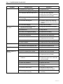
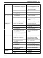
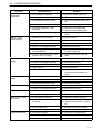
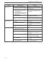
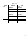
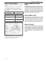
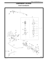
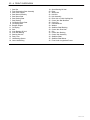
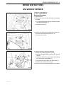
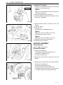
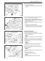
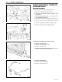
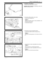
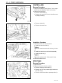
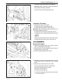
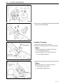
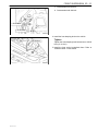
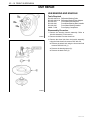
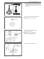
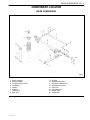
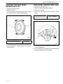
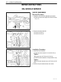
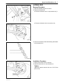
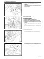
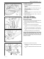
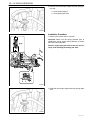
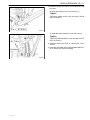
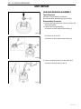
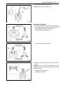
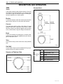
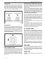
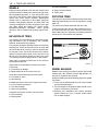
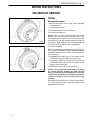
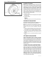
SECTION 2A
SUSPENSION DIAGNOSIS
TABLE OF CONTENTS
Diagnostic Information and Procedures . . . . . 2A-1
General Diagnosis . . . . . . . . . . . . . . . . . . . . . . . . . 2A-1
Wheel Bearing Diagnosis . . . . . . . . . . . . . . . . . . . 2A-6
DIAGNOSTIC INFORMATION AND PROCEDURES
GENERAL DIAGNOSIS
Problems in the steering, the suspension, the tires, and
the wheels involve several systems. Consider all systems when you diagnose a complaint. Some problems,
such as abnormal or excessive tire wear and scuffed
tires, may be the result of hard driving. Always road test
the vehicle first. If possible, do this road test with the
customer.
Proceed with the following preliminary checks. Correct
any substandard conditions.
ÁÁÁÁÁÁÁÁÁ
ÁÁÁÁÁÁÁÁÁÁÁÁÁÁ
ÁÁÁÁÁÁÁÁÁÁÁÁÁÁ
ÁÁÁÁÁÁÁÁÁ
ÁÁÁÁÁÁÁÁÁÁÁÁÁÁ
ÁÁÁÁÁÁÁÁÁÁÁÁÁÁ
Application
Preliminary Checks
DAEWOO M-150 BL2
Checks
Correction
D Inspect the tires for improper pressure
and uneven wear.
D Inflate the tires to the proper pressure.
D Inspect the joint from the steering
column to the intermediate shaft for
loose connections or wear.
D Inspect the joint from the intermediate
shaft to the steering gear for loose
connections or wear.
D Tighten the coupling flange pinch
bolts.
D Replace the intermediate shaft as
needed.
D Inspect the front and the rear
suspension, the steering gear, and the
linkage for loose or damaged parts.
D Tighten the front and the rear
suspension.
D Tighten the steering gear mounting
bracket bolts.
D Replace the front and the rear
suspension as needed.
D Replace the steering gear as needed.
D Replace the coupling flange as
needed.
D Inspect for out–of–round tires.
D Perform free runout test.
D Match–mount the tires.
D Inspect for out–of–balance tires, bent
wheels, and worn or loose wheel
bearings.
D Balance the wheels.
D Replace the wheels.
D Replace the wheel bearings.
D Check the power steering pump drive
belt tension.
D Tighten the power steering pump drive
belt.
D Inspect the power steering system.
Also, check the power steering fluid
level.
D Repair any leaks.
D Perform a power steering gear test.
D Add power steering fluid.
2A – 2 SUSPENSION DIAGNOSIS
ÁÁÁÁÁÁÁÁÁ
ÁÁÁÁÁÁÁÁÁÁÁÁÁÁ
ÁÁÁÁÁÁÁÁÁÁÁÁÁÁ
ÁÁÁÁÁÁÁÁÁ
ÁÁÁÁÁÁÁÁÁÁÁÁÁÁ
ÁÁÁÁÁÁÁÁÁÁÁÁÁÁ
Condition
Car Lead/Pull
Abnormal or Excessive
Tire Wear
Scuffed Tires
Wheel Tramp
Shimmy, Shake, or
Vibration
Probable Cause
Correction
D Mismatched or uneven tires.
D Replace the tires.
D A broken or a sagging coil spring.
D Replace the coil spring.
D A improperly radial tire lateral force.
D Check the wheel alignment.
D Switch the tire and wheel assemblies.
D Replace the tires as needed.
D The front–wheel alignment is
out–of–align.
D Align the front wheels.
D Off–center steering gear.
D Reseat the pinion valve assembly.
D Replace the pinion valve assembly as
needed.
D Front–brake dragging.
D Adjust the front brakes.
D The front–wheel and rear–wheel
alignment is out–of–align.
D Align the front and the rear wheels.
D Excessive toe.
D Adjust the toe.
D A broken or a sagging coil spring.
D Replace the coil spring.
D Out–of–balance tires.
D Balance the tires.
D Worn strut dampeners.
D Replace the strut dampeners.
D A failure to rotate tires.
D Rotate the tires.
D Replace the tires as needed.
D Overloaded vehicle.
D Maintain the proper load weight.
D Low tire inflation.
D Inflate the tires to the proper pressure.
D Incorrect toe.
D Adjust the toe.
D A twisted or a bent suspension arm.
D Replace the suspension arm.
D An out–of–balance tire or wheel.
D Balance the tire or the wheel.
D Improper strut dampener action.
D Replace the strut dampeners.
D An out–of–balance tire or wheel.
D Balance the tire or the wheel.
D Excessive wheel hub runout.
D Measure the hub flange runout.
D Replace the hub as needed.
D Excessive brake drum or brake rotor
imbalance.
D Adjust the brakes.
D Replace the brake rotor or the brake
drum as needed.
D Worn tie rod ends.
D Replace the tie rod ends.
D Wheel trim imbalance.
D Balance the wheel.
D A worn ball joint.
D Replace the control arm and ball joint
assembly.
D Excessive wheel runout.
D Measure the wheel runout.
D Replace the wheel as needed.
D Excessive loaded radial runout on the
tire and wheel assembly.
D Match–mount the tire and wheel
assembly.
DAEWOO M-150 BL2
SUSPENSION DIAGNOSIS 2A – 3
ÁÁÁÁÁÁÁÁÁ
ÁÁÁÁÁÁÁÁÁÁÁÁÁÁ
ÁÁÁÁÁÁÁÁÁÁÁÁÁÁ
ÁÁÁÁÁÁÁÁÁ
ÁÁÁÁÁÁÁÁÁÁÁÁÁÁ
ÁÁÁÁÁÁÁÁÁÁÁÁÁÁ
Condition
Probable Cause
Correction
Hard Steering (Manual)
D A lack of lubrication of the ball joints,
the tie rods and the steering gear.
D Lubricate the ball joints, the tie rods,
and the steering gear.
D Replace the control arm and ball joint
assembly, the tie rods, and the
steering gear as needed.
D The front–wheel alignment is
out–of–align.
D Align the front wheels.
D Steering gear adjustment is
out–of–adjustment.
D Adjust the steering gear.
D The steering preload adjustment is
out–of–adjustment.
D Perform a rack bearing preload
on–vehicle adjustment.
D The leaked hydraulic system.
D Test the power steering system
pressure with a gauge.
D Replace the seals and the hoses as
needed.
D A loose steering gear mounting.
D Tighten the steering gear mounting
bracket bolts.
D Worn or loose wheel bearings.
D Tighten the drive axle nut.
D Replace the wheel bearing as needed.
D A loose steering gear mounting.
D Tighten the steering gear mounting
bracket bolts.
D The steering preload adjustment is
out–of–adjustment.
D Perform a rack bearing preload
on–vehicle adjustment.
D Loose connections or wear of the joint
from the steering column to the
intermediate shaft.
D Loose connections or wear of the joint
from the intermediate shaft to the
steering gear.
D Tighten the coupling pinch bolts.
D Replace the intermediate shaft as
needed.
D Binding in the ball joints.
D Replace the control arm and ball joint
assembly.
D Binding in the steering column.
D Lubricate the steering column.
D Replace the steering column as
needed.
D The front–wheel alignment is
out–of–align.
D Align the front wheels.
D The steering preload adjustment is
out–of–adjustment.
D Perform a rack bearing preload
on–vehicle adjustment.
D A sticking valve.
D Lubricate the pinion valve assembly.
D Replace the pinion valve assembly as
needed.
D Binding in the coupling on the
intermediate shaft.
D Replace the intermediate shaft.
D Damaged suspension components.
D Replace the damaged suspension
components.
D Worn control arm bushings or tie rod
ends.
D Replace the control arm bushings or
the tie rods.
Hard Steering (Power)
Too Much Play in
Steering.
Poor Returnability
Abnormal Noise, Front
Suspension
DAEWOO M-150 BL2
2A – 4 SUSPENSION DIAGNOSIS
ÁÁÁÁÁÁÁÁÁ
ÁÁÁÁÁÁÁÁÁÁÁÁÁÁ
ÁÁÁÁÁÁÁÁÁÁÁÁÁÁ
ÁÁÁÁÁÁÁÁÁ
ÁÁÁÁÁÁÁÁÁÁÁÁÁÁ
ÁÁÁÁÁÁÁÁÁÁÁÁÁÁ
Condition
Abnormal Noise, Front
Suspension
Wander or Poor
Steering Ability
Erratic Steering when
Braking
Low or Uneven Trim
Height
Ride Too Soft
Ride Too Harsh
Body Leans or Sways
in Corners
Suspension Bottoms
Probable Cause
Correction
D A loose stabilizer shaft link.
D Tighten the stabilizer shaft link.
D Loose wheel nuts.
D Tighten the wheel nuts.
D Loose suspension bolts or nuts.
D Tighten the suspension bolts or the
nuts.
D Loose wheel covers.
D Tighten the wheel covers.
D Worn strut dampeners or strut
mountings.
D Replace the strut dampeners.
D Tighten the strut mounting nuts.
D An improperly positioned strut spring.
D Adjust the strut spring to the proper
position.
D Mismatched or uneven tires.
D Replace the tires.
D Worn strut dampeners.
D Replace the strut dampeners.
D A loose stabilizer shaft link.
D Tighten the stabilizer shaft link.
D A broken or a sagging coil spring.
D Replace the coil spring.
D The steering preload adjustment is
out–of–adjustment.
D Perform a rack bearing preload
on–vehicle adjustment.
D The front–wheel and the rear–wheel
alignment are out–of–align.
D Align the front and the rear end
wheels.
D Worn or loose wheel bearings.
D Replace the wheel bearings.
D A broken or a sagging coil spring.
D Replace the coil spring.
D A leaking caliper.
D Replace the caliper.
D Warped rotors.
D Replace the rotors.
D An incorrect or an uneven caster.
D If the caster is beyond specifications,
check the frame and repair it as
needed.
D A broken or a sagging coil spring.
D Replace the coil spring.
D An overloaded vehicle.
D Maintain the proper load weight.
D An incorrect or weak coil spring.
D Replace the coil spring.
D Worn strut dampeners.
D Replace the strut dampeners.
D A broken or a sagging coil spring.
D Replace the coil spring.
D Incorrect strut dampeners.
D Replace the strut dampeners.
D An incorrect coil spring.
D Replace the coil spring.
D A loose stabilizer shaft link.
D Tighten the stabilizer shaft link.
D Worn strut dampeners or strut
mountings.
D Replace the strut dampeners.
D Tighten the strut assembly mounting
nuts.
D an overloaded vehicle.
D Maintain the proper load weight.
D A broken or a sagging coil spring.
D Replace the coil spring.
D Worn strut dampeners.
D Replace the strut dampeners.
D An overloaded vehicle.
D Maintain the proper load weight.
D A broken or a sagging coil spring.
D Replace the coil spring.
DAEWOO M-150 BL2
SUSPENSION DIAGNOSIS 2A – 5
ÁÁÁÁÁÁÁÁÁ
ÁÁÁÁÁÁÁÁÁÁÁÁÁÁ
ÁÁÁÁÁÁÁÁÁÁÁÁÁÁ
ÁÁÁÁÁÁÁÁÁ
ÁÁÁÁÁÁÁÁÁÁÁÁÁÁ
ÁÁÁÁÁÁÁÁÁÁÁÁÁÁ
Condition
Steering Wheel
Kickback (Power)
Steering Wheel Surges
or Jerks (Power)
Cupped Tires
DAEWOO M-150 BL2
Probable Cause
Correction
D Air in the power steering system.
D Bleed the power steering system.
D A loose steering gear mounting.
D Tighten the steering gear mounting
bracket bolts.
D Loose connections or wear of the joint
from the steering column to the
intermediate shaft.
D Loose connections or wear of the joint
from the intermediate shaft to the
steering gear.
D Tighten the coupling pinch bolts.
D Replace the intermediate shaft as
needed.
D Loose tie rod ends.
D Tighten the tie rod ends.
D Replace the tie rods as needed.
D Loose or worn wheel bearings.
D Tighten the drive axle nut.
D Replace the wheel bearing as needed.
D Low pressure in the power steering
system.
D Replace the seals and the hoses as
needed.
D A sluggish steering gear valve.
D Clean the pinion valve assembly.
D Replace the pinion valve assembly as
needed.
D A loose power steering pump drive
belt.
D Adjust the power steering pump drive
belt.
D The front–wheel and the rear–wheel
alignment are out–of–align.
D Align the front and the rear wheels.
D Worn strut dampeners.
D Replace the strut dampeners.
D Worn or loose wheel bearing.
D Tighten the drive axle nut.
D Replace the wheel bearings as
needed.
D Excessive tire or wheel runout.
D Match–mount the tires.
D Replace the tires as needed.
D Replace the wheels as needed.
D A worn ball joints.
D Replace the control arm and ball joint
assembly.
D The steering gear preload adjustment
is out–of–adjustment.
D Perform a rack bearing preload
on–vehicle adjustment.
2A – 6 SUSPENSION DIAGNOSIS
WHEEL BEARING DIAGNOSIS
This vehicle with non–serviceable bearings in the rear
wheels. If any fault is found with a wheel bearing, it must
be replaced.
Wheel Bearing Noise
A road test usually reveals excessive wheel bearing
noise. Wheel bearings emit a howling sound when loose
or damaged. Wheel bearing noise is present only when
the vehicle is moving. It is constant and unwavering and
increases with the speed of the vehicle. If the wheel
bearing noise cannot be positively diagnosed, or if the
origin of the noise cannot be determined, perform the
following test :
1. Raise and suitably support the vehicle.
2. Spin the wheels using your hand. Check for out–of–
round or out–of–balance tires, bent rims, or loose
wheel bearings.
3. Spin the rear wheels using a commercial wheel spiner.
4. If a noise can be heard from the passenger compartment, replace the noisy wheel bearings. Refer to Section 2D, Rear Suspension.
5. Lower the vehicle.
DAEWOO M-150 BL2
SECTION 2B
WHEEL ALIGNMENT
TABLE OF CONTENTS
Description and Operation . . . . . . . . . . . . . . . . . .
Four Wheel Alignment . . . . . . . . . . . . . . . . . . . . .
Toe . . . . . . . . . . . . . . . . . . . . . . . . . . . . . . . . . . . . . .
Caster . . . . . . . . . . . . . . . . . . . . . . . . . . . . . . . . . . .
2B-2
2B-2
2B-2
2B-2
Diagnostic Information and Procedures . . . . .
Tire Diagnosis . . . . . . . . . . . . . . . . . . . . . . . . . . . .
Front Toe Adjustment . . . . . . . . . . . . . . . . . . . . . .
Front Camber and Caster Check . . . . . . . . . . . .
2B-4
2B-4
2B-5
2B-5
Camber . . . . . . . . . . . . . . . . . . . . . . . . . . . . . . . . . .
Steering Axis Inclination . . . . . . . . . . . . . . . . . . . .
Included Angle . . . . . . . . . . . . . . . . . . . . . . . . . . . .
Scrub Radius . . . . . . . . . . . . . . . . . . . . . . . . . . . . .
2B-2
2B-3
2B-3
2B-3
Rear Camber Check . . . . . . . . . . . . . . . . . . . . . . .
Rear Toe Check . . . . . . . . . . . . . . . . . . . . . . . . . . .
Specifications . . . . . . . . . . . . . . . . . . . . . . . . . . . . .
Wheel Alignment Specifications . . . . . . . . . . . . .
2B-5
2B-5
2B-6
2B-6
Setback . . . . . . . . . . . . . . . . . . . . . . . . . . . . . . . . . . 2B-3
Turning Angle . . . . . . . . . . . . . . . . . . . . . . . . . . . . . 2B-3
DAEWOO M-150 BL2
Fastener Tightening Specifications . . . . . . . . . . . 2B-6
2B – 2 WHEEL ALIGNMENT
DESCRIPTION AND OPERATION
FOUR WHEEL ALIGNMENT
CASTER
The first responsibility of engineering is to design safe
steering and suspension systems. Each component
must be strong enough to withstand and absorb extreme
punishment. Both the steering system and the front and
the rear suspension must function geometrically with the
body mass.
The steering and the suspension systems require that
the front wheels self-return and that the tire rolling effort
and the road friction be held to a negligible force in order
to allow the customer to direct the vehicle with the least
effort and the most comfort.
A complete wheel alignment check should include measurements of the rear toe and camber.
Four-wheel alignment assures that all four wheels will be
running in precisely the same direction.
When the vehicle is geometrically aligned, fuel economy
and tire life are at their peak, and steering and performance are maximized.
TOE
D16A008A
Caster is the tilting of the uppermost point of the steering
axis either forward or backward from the vertical when
viewed from the side of the vehicle. A backward tilt is
positive, and a forward tilt is negative. Caster influences
directional control of the steering but does not affect tire
wear. Weak springs or overloading a vehicle will affect
caster. One wheel with more positive caster will pull toward the center of the car. This condition will cause the
car to move or lean toward the side with the least
amount of positive caster. Caster is measured in degrees and is not adjustable.
CAMBER
D16A006A
Toe–in is the turning in of the tires, while toe–out is the
turning out of the tires from the geometric centerline or
thrust line. The toe ensures parallel rolling of the wheels.
The toe serves to offset the small deflections of the
wheel support system which occur when the vehicle is
rolling forward. The specified toe angle is the setting
which achieves–degrees (0_) of toe when the vehicle is
moving.
Incorrect toe-in or toe-out will cause tire wear and reduced fuel economy. As the individual steering and suspension components wear from vehicle mileage,
additional toe will be needed to compensate for the
wear.
Always correct the toe dimension last.
D16A007A
Camber is the tilting of the top of the tire from the vertical
when viewed from the front of the vehicle. When the
tires tilt outward, the camber is positive. When the tires
tilt inward, the camber is negative. The camber angle is
measured in degrees from the vertical. Camber influences both directional control and tire wear.
If the vehicle has too much positive camber, the outside
shoulder of the tire will wear. If the vehicle has too much
negative camber, the inside shoulder of the tire will wear.
Camber is measured in degrees and is not adjustable.
DAEWOO M-150 BL2
WHEEL ALIGNMENT 2B – 3
STEERING AXIS INCLINATION
Steering Axis Inclination (SAI) is the tilt at the top of the
steering knuckle from the vertical. Measure the SAI
angle from the true vertical to a line through the center of
the strut and the lower ball joint as viewed from the front
of the vehicle.
SAI helps the vehicle track straight down the road and
assists the wheel back into the straight ahead position.
SAI on front wheel drive vehicles should be negative.
or add the positive camber readings to the Steering Axis
Inclination (SAI).
SCRUB RADIUS
The scrub radius is the distance between true vertical
and the line through the center of the strut and lower ball
joint to the road surface. Scrub radius is bulit into the design of the vehicle. Scrub radius is not adjustable.
SETBACK
INCLUDED ANGLE
The included angle is the angle measured from the camber angle to the line through the center of the strut and
the lower ball joints as viewed from the front of the vehicle.
The included angle is calculated in degrees Most alignment racks will not measure the included angle directly.
To determine the included angle, subtract the negative
DAEWOO M-150 BL2
The setback is the distance in which one front hub and
bearing assembly may be rearward of the other front
hub and bearing assembly. Setback is primarily caused
by a road hazard or vehicle collision.
TURNING ANGLE
The turning angle is the angle of each front wheel to the
vertical when the vehicle is making a turn.
2B – 4 WHEEL ALIGNMENT
DIAGNOSTIC INFORMATION AND PROCEDURES
TIRE DIAGNOSIS
ÁÁÁÁÁÁÁÁÁÁ
ÁÁÁÁÁÁÁÁÁÁÁÁÁ
ÁÁÁÁÁÁÁÁÁÁÁÁÁÁ
ÁÁÁÁÁÁÁÁÁÁ
ÁÁÁÁÁÁÁÁÁÁÁÁÁ
ÁÁÁÁÁÁÁÁÁÁÁÁÁÁ
ÁÁÁÁÁÁÁÁÁÁ
ÁÁÁÁÁÁÁÁÁÁÁÁÁ
ÁÁÁÁÁÁÁÁÁÁÁÁÁÁ
Condition
Irregular and Excessive
Tire Wear
Premature Tire Wear
Uneven Braking
Noise and Vibration of
The Body
Vibration of The Steering
Wheel
Probable cause
Correction
D Incorrect inflation pressure.
D Inflate the tires to the proper
pressure.
D Inbalanced wheel.
D Balance the wheel.
D Replace the wheel.
D A lack of regular rotation.
D Rotate the tires.
D Incorrect alignment.
D Align the front and rear wheels.
D Excessive inflation pressure.
D Inflate the tires to the proper
pressure.
D High speed driving with the low
inflation pressure.
D Inflate the tires to the proper
pressure.
D Inbalanced inflation pressure.
D Inflate the tires to the proper
pressure.
D Irregular tire wear.
D Replace the tires.
D Low inflation pressure.
D Inflate the tires to the proper
pressure.
D Inbalanced wheel.
D Balance the wheel.
D Replace the wheel.
D Damaged wheel or tire.
D Replace the wheel and the tire.
D Irregular tire wear.
D Replace the tire.
D Irregular tire wear.
D Replace the tire.
D Inbalanced inflation pressure.
D Inflate the tires to the proper
pressure.
D Damaged tire.
D Replace the tire.
D Bent or damaged wheel.
D Replace the wheel.
DAEWOO M-150 BL2
WHEEL ALIGNMENT 2B – 5
FRONT TOE ADJUSTMENT
1. Separate the clamps from the both rack and pinion
boots.
2. Loosen the right and the left tie rod end lock nuts.
3. Turn the right and the left tie rod to align the toe.
In this adjustment, the right and left tie rods must be
equal in length.
ÁÁÁÁÁÁÁÁÁ
ÁÁÁÁÁÁÁÁÁ
ÁÁÁÁÁÁÁÁÁ
ÁÁÁÁÁÁÁÁÁ
ÁÁÁÁÁÁÁÁÁÁ
ÁÁÁÁÁÁÁÁ
ÁÁÁÁÁÁÁÁÁÁ
ÁÁÁÁÁÁÁÁ
ÁÁÁÁÁÁÁÁÁÁ
ÁÁÁÁÁÁÁÁ
ÁÁÁÁÁÁÁÁÁÁ
ÁÁÁÁÁÁÁÁ
ÁÁÁÁÁÁÁÁÁÁ
ÁÁÁÁÁÁÁÁ
ÁÁÁÁÁÁÁÁÁÁ
ÁÁÁÁÁÁÁÁ
Front Toe–In
10′ ± 10′
Rotation Number of Tie Rod
Difference of Toe–In
1/2
0.75 mm (0.03 in.)
1
1.5 mm (0.06 in.)
FRONT CAMBER AND CASTER
CHECK
The front camber and caster are not adjustable. Refer to
“Wheel Alignment Specifications” in this section. Jounce
the bumper three times before measuring the camber or
the caster in order to prevent an incorrect reading. If the
front camber or caster measurements deviate from the
specifications, locate and replace or repair any damaged, loose, bent, dented, or worn suspension part. If
the problem is body related, repair the body.
REAR CAMBER CHECK
The rear camber is not adjustable. Refer to “Wheel
Alignment Specifications” in this section. If the rear camber deviates from the specification, locate the cause and
correct it. If damaged, loose, bent, dented, or worn suspension parts are found, they should be repaired or replaced. If the problem is body related, repair the body.
REAR TOE CHECK
The rear toe is not adjustable. Refer to “Wheel Alignment Specifications” in this section. If the toe deviates
from the specification, check the rear axle assembly and
the wheel spindle on vehicles without an anti–lock braking system (ABS) or the rear axle assembly and the hub
and bearing assembly on vehicles with ABS for possible
damage.
D106A303
4. Tighten the tie rod end lock nut to 45 NSm (33 lb-ft).
5. Install the rack and pinion boots clamp.
DAEWOO M-150 BL2
2B – 6 WHEEL ALIGNMENT
SPECIFICATIONS
WHEEL ALIGNMENT SPECIFICATIONS
ÁÁÁÁÁÁÁÁÁÁÁÁÁÁ
ÁÁÁÁÁÁÁÁÁÁÁÁ
ÁÁÁÁÁÁÁÁÁÁÁ
ÁÁÁÁÁÁÁÁÁÁÁÁÁÁ
ÁÁÁÁÁÁÁÁÁÁÁÁ
ÁÁÁÁÁÁÁÁÁÁÁ
ÁÁÁÁÁÁÁÁÁÁÁÁÁÁÁÁÁÁÁÁÁÁÁÁÁÁ
ÁÁÁÁÁÁÁÁÁÁÁ
Application
Front
Rear
0_30′ ± 0_30′
0_ " 20′
Caster–Manual Steering
2_48′ ± 30′
–
Caster–Power Steering
2_48′ ± 30′
–
Toe–in (2–person load)
10′ ± 10′
20′ " 20′
Camber
FASTENER TIGHTENING SPECIFICATIONS
ÁÁÁÁÁÁÁÁÁÁÁÁÁÁÁÁÁÁ
ÁÁÁÁÁÁÁ
ÁÁÁÁÁÁ
ÁÁÁÁÁÁÁ
ÁÁÁÁÁÁÁÁÁÁÁÁÁÁÁÁÁÁ
ÁÁÁÁÁÁÁ
ÁÁÁÁÁÁ
ÁÁÁÁÁÁÁ
ÁÁÁÁÁÁÁÁÁÁÁÁÁÁÁÁÁÁ
ÁÁÁÁÁÁÁ
ÁÁÁÁÁÁ
ÁÁÁÁÁÁÁ
Application
Tie Rod End Lock Nut
NSm
Lb-Ft
Lb-In
45
33
–
DAEWOO M-150 BL2
SECTION 2C
FRONT SUSPENSION
TABLE OF CONTENTS
Description and Operation . . . . . . . . . . . . . . . . . .
Front Suspension . . . . . . . . . . . . . . . . . . . . . . . . .
Component Locator . . . . . . . . . . . . . . . . . . . . . . . .
Front Suspension . . . . . . . . . . . . . . . . . . . . . . . . .
2C-2
2C-2
2C-3
2C-3
Diagnostic Information and Procedures . . . . .
Strut Dampener . . . . . . . . . . . . . . . . . . . . . . . . . . .
Ball Joint and Knuckle . . . . . . . . . . . . . . . . . . . . .
Front Wheel Bearing . . . . . . . . . . . . . . . . . . . . . . .
2C-5
2C-5
2C-5
2C-6
Repair Instructions . . . . . . . . . . . . . . . . . . . . . . . . . 2C-7
On-Vehicle Service . . . . . . . . . . . . . . . . . . . . . . . . . . 2C-7
Strut Assembly . . . . . . . . . . . . . . . . . . . . . . . . . . . . 2C-7
Knuckle Assembly . . . . . . . . . . . . . . . . . . . . . . . . . 2C-8
DAEWOO M-150 BL2
Front Longitudinal Frame and
Stabilizer Shaft . . . . . . . . . . . . . . . . . . . . . . . . . 2C-10
Control Arm . . . . . . . . . . . . . . . . . . . . . . . . . . . . . 2C-12
Strut Bar . . . . . . . . . . . . . . . . . . . . . . . . . . . . . . . . 2C-12
Crossmember . . . . . . . . . . . . . . . . . . . . . . . . . . . . 2C-13
Unit Repair . . . . . . . . . . . . . . . . . . . . . . . . . . . . . . . .
Hub, Bearing and Knuckle . . . . . . . . . . . . . . . . .
Front Strut . . . . . . . . . . . . . . . . . . . . . . . . . . . . . . .
Specifications . . . . . . . . . . . . . . . . . . . . . . . . . . . .
2C-16
2C-16
2C-20
2C-23
General Specifications . . . . . . . . . . . . . . . . . . . .
Fastener Tightening Specifications . . . . . . . . . .
Special Tools and Equipment . . . . . . . . . . . . . .
Special Tools Table . . . . . . . . . . . . . . . . . . . . . . .
2C-23
2C-23
2C-24
2C-24
2C – 2 FRONT SUSPENSION
DESCRIPTION AND OPERATION
FRONT SUSPENSION
The front suspension for this vehicle is a combination
knuckle/strut and spring design.
The control arms pivot from the body. The lower control
arm pivots use rubber bushing. The upper end of the
strut is isolated by a rubber mount and contains a bearing to allow the wheel to turn.
The lower end of the steering knuckle pivots on a ball
joint bolted to the control arm. The ball joint is fastened
to the steering knuckle with a bolt.
When servicing the control arm-to-body attachment and
the stabilizer shaft-to-body insulators, make sure the attaching bolts are loose until the control arms are moved
to the trim height, which is curb height. Trim height is the
normal position to which the control arms move when
the vehicle is sitting on the ground. Refer to “General
Specifications” in this section.
DAEWOO M-150 BL2
FRONT SUSPENSION 2C – 3
COMPONENT LOCATOR
FRONT SUSPENSION
D16B401A
DAEWOO M-150 BL2
2C – 4 FRONT SUSPENSION
1.
2.
3.
4.
5.
6.
7.
8.
9.
10.
11.
12.
13.
14.
15.
16.
17.
18.
Strut Bar
Front Suspension Strut Assembly
Strut Inner Support
Strut Mount Assembly
Strut Mount Seat
Strut Bearing Seat
Strut Bearing
Coil Spring Upper Seat
Coil Spring Seat
Bumper Stopper
Coil Spring
Strut
Inner Bearing Oil Seal
Inner Hub Bearing
Steering Knuckle
Dust Cover
Hub Bearing Spacer
Outer Hub Bearing
19.
20.
21.
22.
23.
24.
25.
26.
27.
28.
29.
30.
31.
32.
33.
34.
35.
36.
Outer Bearing Oil Seal
Rotor
Wheel Hub
Hub Bolt
Hub Assembly
Drive Axle–to–Hub Caulking Nut
Control Arm Ball Stud Bolt
Cotter Pin
Castellated Nut
Washer
Stabilizer Shaft Bushing
Control Arm Dust Seal
Clip
Control Arm Bushing
Control Arm Assembly
Stabilizer Shaft
Stabilizer Shaft Mount
Front Under Longitudinal Frame
DAEWOO M-150 BL2
FRONT SUSPENSION 2C – 5
DIAGNOSTIC INFORMATION AND PROCEDURES
STRUT DAMPENER
A strut dampener is basically a shock absorber. However, strut dampeners are easier to extend and retract by hand
than are shock absorbers. Strut dampeners are used only on the front in most vehicles, including this vehicle. Shock
absorbers are used on the rear wheels.
ÁÁÁÁÁÁÁÁÁÁ
ÁÁÁÁÁÁÁÁÁÁÁÁÁ
ÁÁÁÁÁÁÁÁÁÁÁÁÁÁ
ÁÁÁÁÁÁÁÁÁÁ
ÁÁÁÁÁÁÁÁÁÁÁÁÁ
ÁÁÁÁÁÁÁÁÁÁÁÁÁÁ
Condition
Struts Seem Weak
Struts are Noisy
Leaks
Probable cause
D Improper tire pressures.
D Adjust the tire pressures to the specifications on the tire placard.
D Abnormal load conditions.
D Consult with the owner to confirm the
owner’s understanding of normal load
conditions.
D Improper compression and rebound
effectiveness of the strut dampener.
D Quickly push down and then lift up on
the corner of the bumper nearest the
strut dampener being tested.
D Compare the compression and rebound with those of a similar vehicle
that has an acceptable ride quality.
D Replace the strut dampener, if needed.
D Loose or damaged mountings.
D Tighten the strut dampener.
D Replace the strut dampener if needed.
D Improper compression and rebound
effectiveness of the strut dampener.
D Quickly push down and then lift up on
the corner of the bumper nearest the
strut dampener being tested.
D Compare the compression and rebound with those of a similar vehicle
that has an acceptable ride quality.
D Replace the strut dampener, if needed.
D A slight trace of fluid.
D The strut dampener is OK.
D Leaks of the seal cover on the fully
extended strut.
D Replace the strut dampener.
D Excessive leaks of fluid on the strut
dampener.
D Replace the strut dampener.
BALL JOINT AND KNUCKLE
Ball Joint Inspection
1. Raise the front of the vehicle to allow the front suspension to hang free.
2. Grasp the tire at the top and the bottom.
3. Move the top of the tire in an in-and-out motion.
4. Look for any horizontal movement of the knuckle relative to the control arm.
5. Control arms assembly must be replaced if the following conditions exist:
D The joint is loose.
D The ball seal is cut.
D The ball stud is disconnected from the knuckle.
DAEWOO M-150 BL2
Correction
D The ball stud is loose at the knuckle.
D The ball stud can be twisted in its socket with finger
pressure.
Ball Stud Inspection
Make sure to check the tightness of the ball stud in the
knuckle boss during each inspection of the ball joint.
One way to inspect the ball stud for wear is to shake the
wheel and feel for movement of the stud end or the castellated nut at the knuckle boss.
Another way to inspect the ball stud for wear is to check
the fastener torque at the castellated nut. A loose nut can
indicate a stressed stud or a hole in the knuckle boss.
Worn or damaged ball joints and knuckles must be replaced.
2C – 6 FRONT SUSPENSION
4. Check the standard torque of the drive nut (spec. :
210 NSm (155 lb-ft)).
FRONT WHEEL BEARING
Bearing Axial End Play Inspection
5. Check the bearing end play according to the following
method.
D Place a dial guage against the disc surface, grasp
the disc.
D Using a push–pull movement, note gage readings.
Specification
D107B303
1. Lift and suitably support the vehicle.
2. Inspect the end play of the bearing.
3. If excessive play is defeeted, free shoes from the disc
or remove the calipers.
0.130mm
or less
(0.005 in)
Standard tighting torque
of drive shaft nut :
210 NSm (155 lb-ft)
6. If the axial end play of the front wheel bearing exceed
0.130mm torque the drive shaft nut successively
(Max. allowance : 240 NSm (177 lb-ft))
7. Check the axial end play again.
8. If the axial end play is above spec., replace the front
wheel bearing.
DAEWOO M-150 BL2
FRONT SUSPENSION 2C – 7
REPAIR INSTRUCTIONS
ON–VEHICLE SERVICE
STRUT ASSEMBLY
Removal Procedure
1. Open the hood.
2. Remove the top of the strut assembly at passenger
seat side.
D For vehicle with power steering, remove the power
steering fluid reservoir (1).
D Remove the nuts (2).
D16B501A
3. Remove the top of the strut assembly at driver side.
D Remove the bolt and the fuse box (1, 2).
D Remove the nuts (3).
D16B502A
4. Remove the lower of the strut assembly.
D Raise and suitably support the vehicle.
D Remove the wheel. Refer to Section 2E, Tires and
Wheels.
D Remove the ABS front speed sensor electrical wire
from the bracket, if applicable (1).
D Disconnect the brake hose from the bracket (2).
D Remove the strut bracket bolts (3).
5. Remove the strut bracket assembly from the vehicle.
D106B503
DAEWOO M-150 BL2
2C – 8 FRONT SUSPENSION
Installation Procedure
70–90 NSm
1. Install the strut assembly to the vehicle with the strut
assembly–to–strut bracket bolts.
Tighten
Tighten the strut assembly–to–strut bracket bolts to
70–90 NSm (52–66 lb-ft).
2. Connect the brake hose to the bracket.
3. Install the ABS front speed sensor electrical wire to
the bracket, if applicable.
D16B504A
4. Install the wheel. Refer to Section 2E, Tires and
Wheels.
5. Lower the vehicle.
6. Install the nuts.
D Install the nuts at passenger side (1).
18–28 NSm
Tighten
Tighten the nuts to 18–28 NSm (13–21 lb-ft).
D Install the nuts at driver side (2).
Tighten
18–28 NSm
D16B505A
Tighten the nuts to 18–28 NSm (13–21 lb-ft).
7. Install the power steering fluid reservoir.
8. Install the fuse box and bolt.
KNUCKLE ASSEMBLY
Tools Required
KM 507–B Ball Joint Remover
Removal Procedure
1. Remove the caulking nut.
D Straighten the bent flange caulking nut (1).
D Remove the caulking nut (2).
D Remove the washer (3).
2. Remove the wheel. Refer to Section 2E, Tires and
Wheels.
D106B506
3. Separate the tie rod end from the knuckle assembly.
D Remove the cotter pin (1).
D Remove the castellated nut (2).
D Install the ball joint remover KM 507–B.
D Separate the tie rod end from the knuckle assembly using a ball joint remover KM 507–B (3).
D105B501
DAEWOO M-150 BL2
FRONT SUSPENSION 2C – 9
4. Remove the control arm from the knuckle assembly.
D Remove the stud bolt (1).
D Separate the control arm from the knuckle assembly (2).
D106B507
5. Remove the brake caliper from the knuckle assembly.
Refer to Section 4D, Front Disc Brakes.
6. Remove the ABS wheel speed sensor from the
knuckle assembly, if applicable. Refer to Section 4F,
Anti–lock Brake System.
7. Remove the steering knuckle assembly from the vehicle.
D Remove the strut bracket bolts (1).
D Separate the knuckle assembly from the drive
shaft by pulling the steering knuckle assembly (2).
D106B508
Installation Procedure
1. Install in the reverse order of removal.
2. Install the steering knuckle assembly in the vehicle
with strut bracket bolts (1).
70–90 NSm
Tighten
Tighten the strut bracket bolts to 70–90 NSm (52–66
lb-ft).
3. Install the brake caliper from the knuckle assembly.
4. Install the control arm into the knuckle assembly with
the stud bolt (2).
50–70 NSm
D16B509A
Tighten
Tighten the stud bolt to 50–70 NSm (36–52 lb-ft).
5. Install the tie rod end to the knuckle assembly.
6. Install the tie rod end–to–knuckle castellated nut (1)
and the cotter pin.
Tighten
Tighten the castellated nut to 30–55 NSm (22–41 lbft).
7. Install the caulking nut (2).
D Bend the caulking nut flange (3).
Tighten
Tighten the caulking nut to 210 NSm (155 lb-ft).
D16B510B
DAEWOO M-150 BL2
2C – 10 FRONT SUSPENSION
FRONT LONGITUDINAL FRAME AND
STABILIZER SHAFT
Removal Procedure
1. Removed the front under longitudinal frame.
D106B511
D Raise and suitably support the vehicle.
D Remove the front wheel. Refer to Section 2E, Tires
and Wheels.
D Remove the transaxle under cover. Refer to Section 5B, Manual Transaxle.
D Remove the front under longitudinal frame bolt (1).
D Remove the front under longitudinal frame nut (2).
D Remove the stabilizer shaft mounting bolts (3).
D Remove the front under longitudinal frame.
D16B512A
2. Remove the stabilizer shaft from the vehicle.
D Remove the cotter pin (1).
D Remove the castellated nut (2).
D Remove the washer (3).
D Remove the rear bushing with separating the stabilizer shaft from the control arm (4).
D106B513
D Remove the bushing (5).
D Remove the wire clamps (6).
D Remove the mountings (7).
D16B514A
DAEWOO M-150 BL2
FRONT SUSPENSION 2C – 11
Installation Procedure
1. Install in the reverse order of removal.
Important: When installing the mountings, position the
opened mountings forward.
D16B515A
2. Install the stabilizer shaft to the vehicle.
D Install the castellated nut.
Tighten
Tighten the stabilizer shaft–to–body castellated nut to
40–50 NSm (30–36 lb-ft).
D Install the cotter pin.
40–50 NSm
D16B516A
3. Install the front under longitudinal frame.
D Install the stabilizer shaft mounting bolts (1).
Tighten
Tighten the mounting bolts to 30–50 NSm (22–36 lbft).
D16B517C
D Install the front under longitudinal frame bolt (2).
Tighten
65 – 80 NSm
Tighten to bolt to 10–14 NSm (89–124 lb-in).
D Install the front under longitudinal frame nut (3).
Tighten
Tighten to nut to 65–80 NSm (48–59 lb-ft).
10 – 14 NSm
D16B518B
DAEWOO M-150 BL2
2C – 12 FRONT SUSPENSION
CONTROL ARM
Removal Procedure
1. Remove the stabilizer shaft. Refer to “Front Longitudinal Frame and Stabilizer Shaft” in this section.
2. Remove the control arm.
D Remove the stud bolt (1).
D Separate the control arm from the knuckle assembly using a lever (2).
D106B519
D Remove the bolt (3).
D Remove the control arm.
D106B520
Installation Procedure
1. Install the control arm onto the vehicle.
D Install the control arm bolt (1).
Tighten
Tighten the control arm bolt to 55–70 NSm (41–52 lbft).
D Install the control arm to the knuckle assembly.
D Install the stud bolt (2).
Tighten
D16B521B
Tighten the stud bolt to 50–70 NSm (36–52 lb-ft).
2. Install the stabilizer shaft.
STRUT BAR
Removal Procedure
1. Open the hood.
2. Remove the strut bar from the vehicle.
D Remove the purge control valve (1).
D Remove the A/C low pressure pipe bracket–to–
strut bar nut (2).
D Remove the strut bar bolts at passenger side (3).
D10B522A
DAEWOO M-150 BL2
FRONT SUSPENSION 2C – 13
D Remove the strut bar bolts at driver side (4).
Important: When removing the bolts using the tool,
do not contact the battery terminal.
D Remove the strut bar at passenger side
D106B523
Installation Procedure
1. Install the strut bar to the vehicle.
D Install the strut bar at passenger side.
D Install the strut bar bolts at driver side (1).
Important: When installing the bolts using the tool, do
not contact the battery terminal.
D Install the strut bar bolts at passenger side (2).
D Install the A/C low pressure pipe bracket–to–strut
bar nut.
Tighten
D16B524B
Tighten the strut bar bolts to 35–55 NSm (25–41 lb-ft).
D Install the purge control valve to the strut bar.
CROSSMEMBER
Removal Procedure
1. Remove the transaxle under cover. Refer to Section
5B, Five–Speed Manual Transaxle.
2. Remove the front under longitudinal frame. Refer to
“Stabilizer Shaft” in this section.
3. Remove the damping bush bolt and nut.
D106B525
4. Disconnect the power steering pressure line from the
crossmember. Refer to Section 6B, Power Steering
Pump.
5. Remove the crossmember from the vehicle.
D Place support jack under the crossmember.
D Remove the bumper fascia screws.
D Remove the rear bolts (1).
D Remove the side bolts (2).
D Lower the support jack and remove the crossmember from the vehicle.
D106B526
DAEWOO M-150 BL2
2C – 14 FRONT SUSPENSION
D106B527
6. Remove the front damping bush bolts and damping
bush from the crossmember.
D106B528
Installation Procedure
35–41 NSm
1. Install in the reverse order of removal.
2. Install the front damping bush to the crossmember.
Tighten
D Tighten the bolts to 45–55 NSm (33–41 lb-ft).
a. Front damping bush bolt.
D Tighten the bolt to 35–41 NSm (25–30 lb-ft).
b. Front damping bush bolt.
45–55 NSm
D16B529A
3. Install the crossmember to the vehicle with the bolts.
Tighten
Tighten the bolts to 17–27 NSm (13–20 lb-ft).
a. Crossmember right rear bolt.
b. Crossmember right side bolt.
17–27 NSm
17–27 NSm
D16B530A
DAEWOO M-150 BL2
FRONT SUSPENSION 2C – 15
c. Crossmember left rear bolt.
d. Crossmember leftt side bolt.
17–27 NSm
17–27 NSm
D16B531A
4. Install the front damping bush to the vehicle.
Tighten
68–83 NSm
Tighten the front damping bush bolt and nut to 68–83
NSm (51–61 lb-ft).
5. Install the front under longitudinal frame. Refer to
“Stabilizer Shaft” in this section.
D16B532A
DAEWOO M-150 BL2
2C – 16 FRONT SUSPENSION
UNIT REPAIR
HUB BEARING AND KNUCKLE
Tools Required
DW 220–020A–01
DW 220–020A–04
DW 340–010
DW 340–020
DW 340–030
09940–71430
Differential Bearing Puller.
Differential Bearing Plate Adapter.
Front Wheel Hub Remover.
Front Wheel Bearing Race Installer.
Front Wheel Bearing Installer.
Front Spring Compressor.
Disassembly Procedure
D106B701
1. Remove the steering knuckle assembly. Refer to
“Knuckle Assembly” in this section.
2. Remove the bolts from the wheel hub.
3. Remove the wheel hub from the knuckle assembly
using the front wheel hub remover DW 340–010.
D Remove the wheel hub using the front wheel hub
remover DW 340–010 (1).
D Remove the bearing spacer (2).
D Remove the brake rotor (3).
D106B702
DAEWOO M-150 BL2
FRONT SUSPENSION 2C – 17
D Remove the wheel bearing from the wheel hub using the differential bearing puller DW 220–020A–01
and differential bearing plate adapter DW 220–
020A–04 (4).
D16B703A
D Remove the oil seal from the wheel hub (5).
Important: Do not use removed oil seal.
D106B704
4. Remove the steering knuckle assembly.
D Remove the oil seal (1).
Important: Do not use removed oil seal.
D Remove the wheel bearing (2).
D106B705
D Remove the outer bearing race (3).
D106B706
DAEWOO M-150 BL2
2C – 18 FRONT SUSPENSION
D Remove the inner bearing race (4).
D106B707
Assembly Procedure
1. Assemble the steering knuckle assembly.
D Assemble the inner bearing race using the front
wheel hub remover DW 340–010 and the front
bearing race installer DW 340–020 (1).
D106B708
D Assemble the outer bearing race using the front
wheel hub remover DW 340–010 and the front
wheel bearing race installer DW 340–020 (2).
D106B709
D Assemble the outer wheel bearing (3).
D Assemble the outer wheel bearing oil seal (4).
D106B710
DAEWOO M-150 BL2
FRONT SUSPENSION 2C – 19
2. Install the wheel hub to steering knuckle assembly.
D Install the brake rotor (1).
D Install the wheel hub to the steering knuckle assembly temporary (2).
D Press the outer wheel bearing into the wheel hub
using the front wheel hub remover DW 340–010
and the front wheel bearing installer DW 340–030
(3).
D106B711
D Tighten the bolts (4).
Tighten
Tighten the bolt to 65 NSm (48 lb-ft).
D16B712A
D Install the bearing spacer (5).
D106B713
D Press the inner wheel bearing into the wheel hub
using the front wheel hub remover DW 340–010
and the front wheel bearing installer DW 340–030
(6).
D106B714
DAEWOO M-150 BL2
2C – 20 FRONT SUSPENSION
D Install the inner wheel bearing oil seal (7).
3. Install the steering knuckle assembly.
Refer to “Knuckle Assembly” in this section.
D106B715
FRONT STRUT (INCLUDING COIL
SPRING)
Tools Required
09940–71430 Front Spring Compressor.
Disassembly Procedure
1. Remove the strut assembly. Refer to “Strut Assembly” in this section.
2. Compress the front spring with the front spring compressor 09940–71430.
D106B716
Caution: During compressing spring, do not make
spring end point to operator or dangerous direction.
3. Fix the strut support using the bench vise and remove
the strut nut.
a. Strut nut.
D106B717
DAEWOO M-150 BL2
FRONT SUSPENSION 2C – 21
4. Remove the coil spring.
D Remove the strut inner support (1).
D Remove the strut mount assembly (2).
D Remove the strut mount seat (3).
D
D
D
D
Remove the strut bearing seat (4).
Remove the strut bearing (5).
Remove the coil spring upper seat (6).
Remove the coil spring seat (7).
D Remove the bumper stopper (8).
D16B718A
Assembly Procedure
50–60 NSm
1. Install the coil spring, front bumper stopper, coil
spring seat, coil spring upper seat, strut bearing,
bearing seat, mounting seat, mount assembly and inner support to the strut.
2. Tighten the strut nut.
D Fix the strut support using the bench vise.
D Tighten the nut.
Tighten
Tighten the strut nut to 50–60 NSm (36–44 lb-ft).
D16B719A
DAEWOO M-150 BL2
2C – 22 FRONT SUSPENSION
3. Inspect the installation of coil spring (1, 2).
4. Install the strut assembly. Refer to “Strut Assembly”
in this section.
D106B720
DAEWOO M-150 BL2
FRONT SUSPENSION 2C – 23
SPECIFICATIONS
GENERAL SPECIFICATIONS
ÁÁÁÁÁÁÁÁÁÁÁÁÁÁÁÁÁ
ÁÁÁÁÁÁ
ÁÁÁÁÁÁÁÁÁÁÁÁÁÁ
ÁÁÁÁÁÁÁÁÁÁÁÁÁÁÁÁÁ
ÁÁÁÁÁÁ
ÁÁÁÁÁÁÁÁÁÁÁÁÁÁ
ÁÁÁÁÁÁÁÁÁÁÁÁÁÁÁÁÁ
ÁÁÁÁÁÁÁÁ
ÁÁÁÁÁÁÁÁÁÁ
ÁÁÁÁÁÁ
ÁÁÁÁÁÁÁÁÁÁÁÁÁÁ
ÁÁÁÁÁÁÁÁ
ÁÁÁÁÁÁÁÁÁÁ
ÁÁÁÁÁÁ
ÁÁÁÁÁÁÁÁÁÁÁÁÁÁ
ÁÁÁÁÁÁÁÁ
ÁÁÁÁÁÁÁÁÁÁ
ÁÁÁÁÁÁ
ÁÁÁÁÁÁÁÁÁÁÁÁÁÁ
ÁÁÁÁÁÁÁÁÁÁÁÁÁÁÁÁÁ
ÁÁÁÁÁÁ
ÁÁÁÁÁÁÁÁÁÁÁÁÁÁ
ÁÁÁÁÁÁÁÁ
ÁÁÁÁÁÁÁÁÁÁ
ÁÁÁÁÁÁÁÁÁÁÁÁÁÁÁÁÁ
ÁÁÁÁÁÁ
ÁÁÁÁÁÁÁÁÁÁÁÁÁÁ
ÁÁÁÁÁÁÁÁÁÁÁÁÁÁÁÁÁ
ÁÁÁÁÁÁ
ÁÁÁÁÁÁÁÁÁÁÁÁÁÁ
ÁÁÁÁÁÁÁÁÁÁÁÁÁÁÁÁÁ
ÁÁÁÁÁÁ
ÁÁÁÁÁÁÁÁÁÁÁÁÁÁ
ÁÁÁÁÁÁÁÁÁÁÁÁÁÁÁÁÁ
ÁÁÁÁÁÁ
ÁÁÁÁÁÁÁÁÁÁÁÁÁÁ
FASTENER TIGHTENING SPECIFICATIONS
ÁÁÁÁÁÁÁÁÁÁÁÁÁÁÁÁÁÁ
ÁÁÁÁÁÁÁ
ÁÁÁÁÁÁ
ÁÁÁÁÁÁÁ
ÁÁÁÁÁÁÁÁÁÁÁÁÁÁÁÁÁÁ
ÁÁÁÁÁÁÁ
ÁÁÁÁÁÁ
ÁÁÁÁÁÁÁ
ÁÁÁÁÁÁÁÁÁÁÁÁÁÁÁÁÁÁ
ÁÁÁÁÁÁÁ
ÁÁÁÁÁÁ
ÁÁÁÁÁÁÁ
ÁÁÁÁÁÁÁÁÁÁÁÁÁÁÁÁÁÁ
ÁÁÁÁÁÁÁ
ÁÁÁÁÁÁ
ÁÁÁÁÁÁÁ
ÁÁÁÁÁÁÁÁÁÁÁÁÁÁÁÁÁÁ
ÁÁÁÁÁÁÁ
ÁÁÁÁÁÁ
ÁÁÁÁÁÁÁ
ÁÁÁÁÁÁÁÁÁÁÁÁÁÁÁÁÁÁ
ÁÁÁÁÁÁÁ
ÁÁÁÁÁÁ
ÁÁÁÁÁÁÁ
ÁÁÁÁÁÁÁÁÁÁÁÁÁÁÁÁÁÁ
ÁÁÁÁÁÁÁ
ÁÁÁÁÁÁ
ÁÁÁÁÁÁÁ
ÁÁÁÁÁÁÁ
ÁÁÁÁÁÁ
ÁÁÁÁÁÁÁÁÁÁÁÁÁÁÁÁÁÁ
ÁÁÁÁÁÁÁ
ÁÁÁÁÁÁÁÁÁÁÁÁÁÁÁÁÁÁ
ÁÁÁÁÁÁÁ
ÁÁÁÁÁÁ
ÁÁÁÁÁÁÁ
ÁÁÁÁÁÁÁÁÁÁÁÁÁÁÁÁÁÁ
ÁÁÁÁÁÁÁ
ÁÁÁÁÁÁ
ÁÁÁÁÁÁÁ
ÁÁÁÁÁÁÁÁÁÁÁÁÁÁÁÁÁÁ
ÁÁÁÁÁÁÁ
ÁÁÁÁÁÁ
ÁÁÁÁÁÁÁ
ÁÁÁÁÁÁÁÁÁÁÁÁÁÁÁÁÁÁ
ÁÁÁÁÁÁÁ
ÁÁÁÁÁÁ
ÁÁÁÁÁÁÁ
ÁÁÁÁÁÁÁÁÁÁÁÁÁÁÁÁÁÁ
ÁÁÁÁÁÁÁ
ÁÁÁÁÁÁ
ÁÁÁÁÁÁÁ
ÁÁÁÁÁÁÁÁÁÁÁÁÁÁÁÁÁÁ
ÁÁÁÁÁÁÁ
ÁÁÁÁÁÁ
ÁÁÁÁÁÁÁ
ÁÁÁÁÁÁÁÁÁÁÁÁÁÁÁÁÁÁ
ÁÁÁÁÁÁÁ
ÁÁÁÁÁÁ
ÁÁÁÁÁÁÁ
ÁÁÁÁÁÁÁ
ÁÁÁÁÁÁ
ÁÁÁÁÁÁÁÁÁÁÁÁÁÁÁÁÁÁ
ÁÁÁÁÁÁÁ
ÁÁÁÁÁÁÁÁÁÁÁÁÁÁÁÁÁÁ
ÁÁÁÁÁÁÁ
ÁÁÁÁÁÁ
ÁÁÁÁÁÁÁ
ÁÁÁÁÁÁÁÁÁÁÁÁÁÁÁÁÁÁ
ÁÁÁÁÁÁÁ
ÁÁÁÁÁÁ
ÁÁÁÁÁÁÁ
Application
Unit
Description
–
Mcpherson (Strut)
Maximum Length
mm (in.)
475–481 (18.7–18.94)
Minimum Length
mm (in.)
321–327 (12.64–12.87)
Stroke
mm (in.)
154 (6.06)
Stabilizer Shaft Diammeter
mm (in.)
24 (0.94)
Coil Spring Height (No Load)
mm (in.)
374 (14.72 )
–
M–8143 ANTIF BRG GREASE
Suspension Type
Shock Absorber
Grease Type (Front Wheel Bearing and Hub)
Application
NSm
Lb-Ft
Lb-In
Strut Assembly–to–Body Nuts
18 – 28
13 – 21
–
Strut Closure Nut
50 – 60
36 – 44
–
Strut Assembly–to–Knuckle Bolts
70 – 90
52 – 66
–
Control Arm Mounting Bolt
55 – 70
41 – 52
–
Control Arm Ball Stud Bolt
50 – 70
36 – 52
–
Stabilizer Shaft Castellated Nut
40 – 50
30 – 36
–
Stabilizer Shaft Mounting Bolt
30 – 50
22 – 36
–
Front Under Longitudinal Frame Bolts
10 – 14
–
89 – 124
Front Under Longitudinal Frame Nut
65 – 80
48 – 59
–
210
155
–
Crossmember Bolt
17 – 27
13 – 20
–
Strut Bar Bolts
35 – 55
25 – 41
–
ABS Front Speed Sensor Retaining Bolt
18 – 28
13 – 21
–
Wheel Hub–to–Brake Disc Bolt
55 – 75
41 – 55
–
Drive Axle–to–Hub Caulking Nut
DAEWOO M-150 BL2
2C – 24 FRONT SUSPENSION
SPECIAL TOOLS AND EQUIPMENT
SPECIAL TOOLS TABLE
DW 220–020A–01
Differential Bearing
Puller
DW 340–030
Front Wheel Bearing
Installer
D106B103
D13B112A
DW 220–020A–04
Differential Bearing
Plate Adapter
D13B113A
KM 507–B
Ball Joint Remover
D105B101
DW 340–010
Front Wheel Hub
Remover
D16B101A
09940–71430
Front Spring
Compressor
D106B104
DW 340–020
Front Wheel Bearing
Race Installer
D106B102
DAEWOO M-150 BL2
SECTION 2D
REAR SUSPENSION
TABLE OF CONTENTS
Description and Operation . . . . . . . . . . . . . . . . . .
Rear Suspension . . . . . . . . . . . . . . . . . . . . . . . . . .
Component Locator . . . . . . . . . . . . . . . . . . . . . . . .
Rear Suspension . . . . . . . . . . . . . . . . . . . . . . . . . .
2D-2
2D-2
2D-3
2D-3
Diagnostic Information and Procedures . . . . .
Rear Suspension . . . . . . . . . . . . . . . . . . . . . . . . . .
Checking the Rear Wheel Bearing
End Play . . . . . . . . . . . . . . . . . . . . . . . . . . . . . . .
Rear Wheel Bearing Free Load . . . . . . . . . . . . . .
2D-4
2D-4
2D-5
2D-5
Repair Instructions . . . . . . . . . . . . . . . . . . . . . . . . . 2D-6
On-Vehicle Service . . . . . . . . . . . . . . . . . . . . . . . . . . 2D-6
DAEWOO M-150 BL2
Shock Absorber . . . . . . . . . . . . . . . . . . . . . . . . . . .
Lateral Rod . . . . . . . . . . . . . . . . . . . . . . . . . . . . . . .
Trailing Arm . . . . . . . . . . . . . . . . . . . . . . . . . . . . . .
Rear Axle Assembly . . . . . . . . . . . . . . . . . . . . . . .
Unit Repair . . . . . . . . . . . . . . . . . . . . . . . . . . . . . . . .
Hub and Bearing Assembly . . . . . . . . . . . . . . . .
Specifications . . . . . . . . . . . . . . . . . . . . . . . . . . . .
General Specifications . . . . . . . . . . . . . . . . . . . .
2D-6
2D-7
2D-8
2D-9
2D-12
2D-12
2D-15
2D-15
Fastener Tightening Specifications . . . . . . . . . . 2D-15
Special Tools and Equipment . . . . . . . . . . . . . . 2D-16
Special Tools Table . . . . . . . . . . . . . . . . . . . . . . . 2D-16
2D – 2 REAR SUSPENSION
DESCRIPTION AND OPERATION
REAR SUSPENSION
The rear suspension consists of an axle with trailing
arms and a lateral rod, two coil springs, two shock absorbers, two upper spring seats, and two bump stop-
pers. The axle structure maintains the relationship of the
wheels to the body.
Each coil spring is retained between a seat in the underbody and a seat welded to the top of the rear axle.
DAEWOO M-150 BL2
REAR SUSPENSION 2D – 3
COMPONENT LOCATOR
REAR SUSPENSION
D106C401
1.
2.
3.
4.
5.
6.
7.
8.
Shock Absorber
Bumper Stopper
Coil Spring Upper Seat
Coil Spring
Washer
Bushing
Lateral Rod
Rear Axle
DAEWOO M-150 BL2
9.
10.
11.
12.
13.
14.
15.
16.
Oil Seal
Wheel Bearing Inner
ABS Wheel Speed Ring
Wheel Bearing Outer
Cotter Pin
Castellated Nut
Spindle Cap
Trailing Arm
2D – 4 REAR SUSPENSION
DIAGNOSTIC INFORMATION AND PROCEDURES
REAR SUSPENSION
ÁÁÁÁÁÁÁÁÁÁ
ÁÁÁÁÁÁÁÁÁÁÁÁÁ
ÁÁÁÁÁÁÁÁÁÁÁÁÁÁ
ÁÁÁÁÁÁÁÁÁÁ
ÁÁÁÁÁÁÁÁÁÁÁÁÁ
ÁÁÁÁÁÁÁÁÁÁÁÁÁÁ
ÁÁÁÁÁÁÁÁÁÁ
ÁÁÁÁÁÁÁÁÁÁÁÁÁ
ÁÁÁÁÁÁÁÁÁÁÁÁÁÁ
Condition
Noise
Uncomfortable
Vehicle Leans Toward
the Side
Probable cause
Correction
D The loosened joints.
D Tighten the joints.
D Wheel bearing is worn or damaged.
D Replace the wheel bearing.
D Faulty shock absorber.
D Replace the shock absorber.
D Faulty shock absorber.
D Replace the shock absorber.
D Faulty coil spring.
D Replace the coil spring.
D Lateral rod bushing is worn or
damaged.
D Replace the lateral rod bushing.
D Trailing arm bushing is worn or
damaged.
D Replace the trailing arm bushing.
D Rear axle deformation.
D Replace the rear axle.
D Lateral rod deformation.
D Replace the lateral rod.
D Trailing arm deformation.
D Replace the trailing arm.
D Faulty coil spring.
D Replace the coil spring.
D Lateral rod bushing is worn or
damaged.
D Replace the lateral rod bushing.
D Trailing arm bushing is worn or
damaged.
D Replace the trailing arm bushing.
DAEWOO M-150 BL2
REAR SUSPENSION 2D – 5
CHECKING THE REAR WHEEL
BEARING END PLAY
REAR WHEEL BEARING FREE LOAD
1. Release the parking brake.
2. Raise the vehicle.
3. Check the wheel bearing play by moving the top and
the down of the tire in an in–and–out motion.
2. Raise the vehicle and rotate the wheel.
3. Remove the wheels.
4. Check the torque when the hub moves by a spring
scale.
1. Release the parking brake.
ÁÁÁÁÁÁÁÁÁ
ÁÁÁÁÁÁÁÁÁ
ÁÁÁÁÁÁÁÁÁ
ÁÁÁÁÁÁÁÁÁ
ÁÁÁÁÁÁÁÁÁ
ÁÁÁÁÁÁÁÁÁ
Standard (No Load)
ÁÁÁÁÁÁÁÁÁÁÁ
ÁÁÁÁÁÁÁ
ÁÁÁÁÁÁÁÁÁÁÁ
ÁÁÁÁÁÁÁ
ÁÁÁÁÁÁÁÁÁÁÁ
ÁÁÁÁÁÁÁ
0.137 – 0.422 NSm
(0.9 – 3.7 lb-in)
D106C301
Rear Wheel Bearing Play
0 mm (0 in.)
4. If the bearing play is high, tighten the castellated nut.
5. If the bearing play is high after tightening, replace the
wheel bearing.
DAEWOO M-150 BL2
D106C302
5. If the checked torque exceeds the specification, tighten the castellated nut.
6. If the checked torque exceeds the specification after
tightening, replace the wheel bearing.
2D – 6 REAR SUSPENSION
REPAIR INSTRUCTIONS
ON–VEHICLE SERVICE
SHOCK ABSORBER
Removal Procedure
1. Support the rear axle with adjustable jack stands.
D Raise the vehicle and support the rear axle assembly (1, 2).
D106C501
2. Remove the shock absorber.
D Remove the bolt (1).
D Remove the nut (2).
D106C502
Installation Procedure
1. Install the shock absorber.
D Install the shock absorber–to–rear axle bolt (1).
Tighten
Tighten the bolt to 45–70 NSm (33–52 lb-ft).
D Install the shock absorber–to–body bracket nut (2).
Tighten
Tighten the shock absorber nut to 45–70 NSm (33–52
lb-ft).
2. Remove the jack stand and lower the vehicle.
D16C503B
DAEWOO M-150 BL2
REAR SUSPENSION 2D – 7
LATERAL ROD
Removal Procedure
1. Raise and suitably support the vehicle.
2. Remove the lateral rod.
D Remove the lateral rod–to– body bracket bolt (1).
D106C504
D Remove the lateral rod–to–rear axle nut (2).
D106C505
2. Remove the lateral rod axle side bushing and washer
from the lateral rod.
D106C506
Installation Procedure
1. Install in the reverse order of removal.
2. Install the lateral rod–to–rear axle side nut.
Tighten
Tighten the lateral rod axle side nut to 35–55 NSm
(25–41 lb-ft).
D16C507A
DAEWOO M-150 BL2
2D – 8 REAR SUSPENSION
3. Install the lateral rod–to–body bracket bolt.
Tighten
Tighten the lateral rod–to–body bracket bolt to 50–70
NSm (37–52 lb-ft).
D16C508B
TRAILING ARM
Removal Procedure
1. Raise and suitably support the vehicle.
2. Support the rear axle with adjustable jack stands.
3. Separate the rear shock absorber from the rear axle
assembly.
D Loosen the shock absorber–to–body bracket nut
(1).
D Remove the shock absorber–to–rear axle bolt (2).
D106C509
4. Remove the trailing arm.
D Remove the trailing arm–to–rear axle bolts (1).
D106C510
D Remove the trailing arm–to–body bracket bolt (2).
D106C511
DAEWOO M-150 BL2
REAR SUSPENSION 2D – 9
Installation Procedure
1. Install the trailing arm.
D Install the trailing arm–to–body bracket bolt (1).
Tighten
Tighten the trailing arm–to–body bracket bolt to 70–
90 NSm (55–66 lb-ft).
D Install the trailing arm–to–rear axle bolts (2).
Tighten
Tighten the trailing arm–to–rear axle bolts to 80–90
NSm (59–66 lb-ft).
D16C515A
2. Install the rear shock absorber. Refer to “Shock Absorber” in this section.
REAR AXLE ASSEMBLY
(INCLUDING COIL SPRING)
Removal Procedure
1. Remove the rear brake drum, shoe and brake plate.
Refer to Section 4E, Rear Drum Brakes.
2. Remove the lateral rod. Refer to “Lateral Rod” in this
section.
D106C516
3. Disconnect the rear axle and the trailing arm.
D Support the rear axle with adjustable jack stands
(1).
D Remove the shock absorber–to–rear axle bolt (2).
D Loosen the shock absorber–to–body bracket nut
(3).
D Remove the trailing arm–to–rear axle bolt (4).
Caution: When disconnecting the rear axle and the
trailing arm, coil spring tension may cause the adjustable jack stand to slip from the rear axle. This
may result in personal injury. Carry out the operation with co–worker.
D106C517
4. Remove the rear axle from the vehicle.
D Remove the coil spring by lowering the jack stand
slowly (1).
D Lower the support jack and remove the rear axle
(2).
D106C518
DAEWOO M-150 BL2
2D – 10 REAR SUSPENSION
5. Remove the rear bumper stopper and rear spring upper seat.
a. Rear bumper stopper.
b. Rear spring upper seat.
D106C519
Installation Procedure
1. Install in the reverse order of removal.
Important: Make sure the spring diameter prior to
installing the spring. Upper spring diameter is smaller
than lower spring diameter.
Caution: Support the jack stand to the rear axle securely until installing the trailing arm bolts.
D106C520
2. Install the rear bumper stopper and rear spring upper
seat.
D106C519
DAEWOO M-150 BL2
REAR SUSPENSION 2D – 11
3. Install the trailing arm and the shock absorber to the
rear axle.
D Install the trailing arm–to–rear axle bolt (1).
Tighten
Tighten the trailing arm–to–rear axle bolt to 80–90
NSm (59–66 lb-ft).
D16C517C
D Install the shock absorber–to–rear axle bolt (2).
Tighten
Tighten the shock absorber–to–rear axle bolt to 45–70
NSm (33–52 lb-ft).
4. Install the lateral rod. Refer to “Lateral Rod” in this
section.
5. Install the rear brake drum, shoe and brake plate. Refer to Section 4E, Rear Drum Brake.
D16C516C
DAEWOO M-150 BL2
2D – 12 REAR SUSPENSION
UNIT REPAIR
HUB AND BEARING ASSEMBLY
Tools Required
DW 340–010 Front Wheel Hub Remover
DW 350–030 Rear Wheel Bearing Race Installer
Disassembly Procedure
1. Remove the rear brake drum. Refer to Section 4E,
Rear Drum Brakes.
2. Remove the rear wheel bearing.
D Remove the outer tapered roller bearing (1).
D106C701
D Remove the oil seal (2).
D Remove the inner tapered roller bearing (3).
D106C702
3. Remove the bearing races from the brake drum.
D Remove the inner bearing race (1).
D106C703
DAEWOO M-150 BL2
REAR SUSPENSION 2D – 13
D Remove the outer bearing race (2).
Important: Use only new bearing race.
D106C704
Assembly Procedure
1. Press the bearing race into the break drum using the
front wheel hub remover DW 340–010 and the rear
wheel bearing race installer DW 350–030.
D Press the inner bearing race (1).
D106C705
D Press the outer bearing race (2).
D106C706
2. Install the wheel bearing and oil seal into the brake
drum.
Important: Coat or fill all the hollow spaces of both
wheel bearing, the ring seal lip and the brake drum with
antifriction grease.
D Install the inner bearing (1).
D Install the oil seal (2).
D106C707
DAEWOO M-150 BL2
2D – 14 REAR SUSPENSION
D Install the outer bearing (3).
3. Install the brake drum. Refer to Section 4E, Rear
Drum Brakes.
4. Adjust the end play and free load of the bearing. Refer to “Check and Adjustments” in this section.
D106C708
DAEWOO M-150 BL2
REAR SUSPENSION 2D – 15
SPECIFICATIONS
GENERAL SPECIFICATIONS
ÁÁÁÁÁÁÁÁÁÁÁÁÁÁÁÁ
ÁÁÁÁÁÁÁÁÁÁÁÁÁÁÁÁÁÁÁÁ
ÁÁÁÁÁÁÁÁÁÁÁÁÁÁÁÁ
ÁÁÁÁÁÁ
ÁÁÁÁÁÁÁÁÁÁÁÁÁÁ
ÁÁÁÁÁÁÁÁÁÁÁÁÁÁÁÁ
ÁÁÁÁÁÁÁÁÁ
ÁÁÁÁÁÁÁÁ
ÁÁÁÁÁÁÁÁÁÁÁÁÁÁ
ÁÁÁÁÁÁÁÁÁ
ÁÁÁÁÁÁÁÁ
ÁÁÁÁÁÁÁÁÁÁÁÁÁÁ
ÁÁÁÁÁÁÁÁÁ
ÁÁÁÁÁÁÁÁ
ÁÁÁÁÁÁÁÁÁÁÁÁÁÁ
ÁÁÁÁÁÁÁÁÁ
ÁÁÁÁÁÁÁÁ
ÁÁÁÁÁÁÁÁÁÁÁÁÁÁ
ÁÁÁÁÁÁÁÁÁ
ÁÁÁÁÁÁÁÁ
ÁÁÁÁÁÁÁÁÁÁÁÁÁÁ
ÁÁÁÁÁÁÁÁÁÁÁÁÁÁÁÁ
ÁÁÁÁÁÁÁÁÁÁÁÁÁÁ
ÁÁÁÁÁÁÁÁÁ
ÁÁÁÁÁÁÁÁ
ÁÁÁÁÁÁÁÁÁÁÁÁÁÁÁÁ
ÁÁÁÁÁÁÁÁÁÁÁÁÁÁ
Application
Unit
Description
–
Isolated Trailing Link
Maximum Length
mm (in.)
394.5 ± 3 (15.53 ± 0.12)
Minimum Length
mm (in.)
257.5 ± 3 (10.14 ± 0.12)
Stroke
mm (in.)
137 (5.39)
Clearance
mm (in.)
0
NSm (lb-in.)
0.137 – 0.422 (0.9 – 3.7)
mm (in.)
291 (11.46)
–
M–8143 ANTIF BRG GREASE
Suspension Type
Shock Absorber
Rear Wheel Bearing
No Load
Coil Spring Height (No Load)
Grease Type (Rear Wheel Bearing and Hub)
ÁÁÁÁÁÁÁÁÁÁÁÁÁÁÁÁÁÁ
ÁÁÁÁÁÁÁ
ÁÁÁÁÁÁ
ÁÁÁÁÁÁÁ
ÁÁÁÁÁÁÁÁÁÁÁÁÁÁÁÁÁÁ
ÁÁÁÁÁÁÁ
ÁÁÁÁÁÁ
ÁÁÁÁÁÁÁ
ÁÁÁÁÁÁÁÁÁÁÁÁÁÁÁÁÁÁ
ÁÁÁÁÁÁÁ
ÁÁÁÁÁÁ
ÁÁÁÁÁÁÁ
ÁÁÁÁÁÁÁÁÁÁÁÁÁÁÁÁÁÁ
ÁÁÁÁÁÁÁ
ÁÁÁÁÁÁ
ÁÁÁÁÁÁÁ
ÁÁÁÁÁÁÁÁÁÁÁÁÁÁÁÁÁÁ
ÁÁÁÁÁÁÁ
ÁÁÁÁÁÁ
ÁÁÁÁÁÁÁ
ÁÁÁÁÁÁÁÁÁÁÁÁÁÁÁÁÁÁ
ÁÁÁÁÁÁÁ
ÁÁÁÁÁÁ
ÁÁÁÁÁÁÁ
ÁÁÁÁÁÁÁÁÁÁÁÁÁÁÁÁÁÁ
ÁÁÁÁÁÁÁ
ÁÁÁÁÁÁ
ÁÁÁÁÁÁÁ
ÁÁÁÁÁÁÁÁÁÁÁÁÁÁÁÁÁÁ
ÁÁÁÁÁÁÁ
ÁÁÁÁÁÁ
ÁÁÁÁÁÁÁ
ÁÁÁÁÁÁÁÁÁÁÁÁÁÁÁÁÁÁ
ÁÁÁÁÁÁÁ
ÁÁÁÁÁÁ
ÁÁÁÁÁÁÁ
ÁÁÁÁÁÁÁÁÁÁÁÁÁÁÁÁÁÁ
ÁÁÁÁÁÁÁ
ÁÁÁÁÁÁ
ÁÁÁÁÁÁÁ
FASTENER TIGHTENING SPECIFICATIONS
Application
NSm
Lb-Ft
Lb-In
Shock Absorber–to–Body Bracket Nut
45 – 70
33 – 52
–
Shock Absorber–to–Rear Axle Bolt
45 – 70
33 – 52
–
Trailing Arm–to–Rear Axle Bolt
80 – 90
59 – 66
–
Trailing Arm–to–Body Bracket Bolt
70 – 90
55 – 66
–
Lateral Rod–to–Body Bracket Bolt
50 – 70
37 – 52
–
Lateral Rod–to–Rear Axle Nut
35 – 55
25 – 41
–
–
–
–
9 – 13
–
80 – 115
Rear Axle Castellated Nut*
ABS Rear Speed Sensor Retaining Bolt
Q Rear Axle Castellated Nut : Refer to Section 4E, Rear Drum Brakes
DAEWOO M-150 BL2
2D – 16 REAR SUSPENSION
SPECIAL TOOLS AND EQUIPMENT
SPECIAL TOOLS TABLE
DW 340–010
Front Wheel Hub
Remover
D16B101A
DW 350–030
Rear Wheel Bearing
Race Installer
D106C101
DAEWOO M-150 BL2
SECTION 2E
TIRES AND WHEELS
TABLE OF CONTENTS
Description and Operation . . . . . . . . . . . . . . . . . .
Tire . . . . . . . . . . . . . . . . . . . . . . . . . . . . . . . . . . . . . .
Replacement Tires . . . . . . . . . . . . . . . . . . . . . . . .
All Season Tires . . . . . . . . . . . . . . . . . . . . . . . . . . .
2E-2
2E-2
2E-3
2E-3
Repair Instructions . . . . . . . . . . . . . . . . . . . . . . . . .
On-Vehicle Service . . . . . . . . . . . . . . . . . . . . . . . . . .
Wheel . . . . . . . . . . . . . . . . . . . . . . . . . . . . . . . . . . .
On-Vehicle Balancing . . . . . . . . . . . . . . . . . . . . . .
Tire Label . . . . . . . . . . . . . . . . . . . . . . . . . . . . . . . .
Spare Tire . . . . . . . . . . . . . . . . . . . . . . . . . . . . . . . .
Wheels . . . . . . . . . . . . . . . . . . . . . . . . . . . . . . . . . .
Inflation of Tires . . . . . . . . . . . . . . . . . . . . . . . . . . .
2E-3
2E-3
2E-4
2E-4
Off-Vehicle Balancing . . . . . . . . . . . . . . . . . . . . . . 2E-8
Correcting Non-Uniform Tires . . . . . . . . . . . . . . . 2E-8
Tire and Wheel Match-Mounting . . . . . . . . . . . . . 2E-9
Specifications . . . . . . . . . . . . . . . . . . . . . . . . . . . . 2E-10
Rotation Tires . . . . . . . . . . . . . . . . . . . . . . . . . . . . . 2E-4
Wheel Balance . . . . . . . . . . . . . . . . . . . . . . . . . . . . 2E-4
Diagnostic Information and Procedures . . . . . 2E-5
Tire Size and Pressure Specifications . . . . . . . 2E-10
Inflation Pressure Conversion
Specifications . . . . . . . . . . . . . . . . . . . . . . . . . . 2E-10
Fastener Tightening Specifications . . . . . . . . . . 2E-10
Tire Wear . . . . . . . . . . . . . . . . . . . . . . . . . . . . . . . . 2E-5
Irregular or Excessive Tires Wear . . . . . . . . . . . . 2E-6
DAEWOO M-150 BL2
2E-7
2E-7
2E-7
2E-8
2E – 2 TIRES AND WHEELS
DESCRIPTION AND OPERATION
Nomenclature
TIRE
Tread
A part (that contacts) road surfaces directly is fixed on
the outside of carcass and breaker. It is a strong rubber
coat made of high anti–abrasion rubber. Its running performance depends on is surface profile.
Breaker
A cord belt between tread and carcass prevents damages of inner code due to outer shock and vibration.
Carcass
This major part made by pilling code papers of strong
synthetic fiber forms a structure of tire. Since it maintains tire pressure and endures applied load and shock
to tire, it should have a high anti–fatigue characteristic.
Bead
A steel wire winding the ending part of carcass code,
coated with rubber film and wrapped with nylon cord papers. It fixes tire to a rim.
Tube
Tires used in mostly current vehicle are mostly tubeless
tires.
D16A002A
Side Wall
It is provided to improve the comfortable driving by protecting carcass and cushion movement.
Structure of Tubeless Tube
ÁÁÁÁÁ
ÁÁÁ
ÁÁÁÁÁÁÁÁÁÁÁ
ÁÁÁ
ÁÁÁÁÁÁÁÁÁÁÁ
ÁÁÁÁÁ
ÁÁÁÁÁ
ÁÁÁÁÁ
ÁÁÁÁÁ
ÁÁÁÁÁ
ÁÁÁÁÁ
ÁÁÁÁÁ
175/60R13
77H
175
Width (mm)
60
Flatness ratio 60%
(Height/Width) × 100
R
Radial
13
Rim diameter (= Tire I.D, Inch)
77
Max. load index
H
Max. speed symbol
D16A001A
DAEWOO M-150 BL2
TIRES AND WHEELS 2E – 3
Hydroplaning
The condition of driving a vehicle fast on the road surface
covered with water can cause tires to fail to rotate with a
good contact on the surface, so results in remaining them
afloat. This is so–called hydroplaning. It causes brake
failure, lower tractive force, and losing the steering performance so it is very vulnerable condition.
Caution: Do not mix different types of tires on the
same vehicle such as radial, bias and bias-belted
tires except in emergencies, because vehicle handling may be seriously affected and may result in
loss of control.
Caution: Do not change 145/70 R13 tires or 155/65
R13 tires for 175/60 R13 tires, because vehicle
hancling may be seriously affected and may result
in loss of control. If you change 145/70 R13 tires or
155/65 R13 tires for 175/60 R13 tires, you have to
change the steering gear assembly.
Use only replacement tires with the same size, load
range, and construction as the original. The use of any
other tire size or construction type may seriously affect
ride, handling, speedometer/odometer calibration, vehicle ground clearance, and tire clearance to the body
and the chassis. This does not apply to the spare tire furnished with the vehicle.
It is recommended that new tires be installed in pairs on
the same axle.
D16A005A
Standing Wave
During running the rotating tire repeats deformation and
restoring movement generated in tread. But when the
wheel rotating speed reaches high, the next deformation
applied to tire before restoring last deformation so the
trembling wave appears in the tread portion. The lower
the tire pressure the severe the trembling wave appears.
And during the high speed.
D106A004
REPLACEMENT TIRES
A Tire Performance Criteria (TPC) specification number
is molded in the sidewall near the tire size of all original
equipment tires. This specification number assures that
the tire meets performance standards for traction, endurance, dimensions, noise, handling and rolling resistance. Usually a specific TPC number is assigned to
each tire size.
DAEWOO M-150 BL2
If it is necessary to replace only one tire, pair it with the
tire having the most tread to equalize the braking action.
Although they may appear different in tread design, tires
built by different manufacturers with identical TPC specifications may be used on the same vehicle.
ALL SEASON TIRES
Most vehicles are now equipped with steel-belted all
season radial tires as standard equipment. These tires
qualify as snow tires, with a 37 percent higher average
rating for snow traction than the non-all season radial
tires previously used. Other performance areas, such as
wet traction, rolling resistance, tread life, and air retention, have also been improved. This was done by improvements in both tread design and tread compounds.
These tires are identified by an “M + S” molded in the tire
sidewall following the size number. The suffix “MS” is
also molded in the sidewall after the TPC specification
number.
The optional handling tires used on some vehicles are
not all season tires. These will not have the “MS” marking after the tire size or the TPC specification number.
TIRE LABEL
The tire label is permanently located on the rear face of
the driver’s door and should be referred to for tire information. It lists the maximum vehicle load, the tire size
(including the spare tire), and the cold inflation pressure
(including the spare tire).
SPARE TIRE
This vehicle comes equipped with a full-sized spare tire
and wheel.
2E – 4 TIRES AND WHEELS
WHEELS
Wheels must be replaced if they are bent, dented, have
excessive lateral or radial runout, leak air through welds,
have elongated bolt holes, or if the wheel bolts won’t
stay tight or are heavily rusted. Wheels with excessive
runout may cause vehicle vibration. Replacement
wheels must be equivalent to the original equipment
wheels in load capacity, diameter, rim width, offset, and
mounting configuration. A wheel of improper size or type
may affect wheel and bearing life, brake cooling,
speedometer/odometer calibration, vehicle ground
clearance, and tire clearance to the body and the chassis.
D Reduced handling
D Swerve on acceleration
D Torque steer
ROTATION TIRES
Front and rear tires perform different jobs and can wear
differently depending on the tires of road driven, driving
habit, etc.
The front tires will wear faster than the rear ones.
To avoid uneven wear of tires and to prolong tire life, inspect and rotate the tires every 5,000 km (3,100 miles).
After rotating the tires, adjust the tire inflation pressures
and be sure to check wheel nuts tightness.
INFLATION OF TIRES
The pressure recommended for any vehicle line is carefully calculated to give a satisfactory ride, handling,
tread life, and load-carrying capacity.
Tire pressure should be checked monthly or before any
extended trip. Check the tires when they are cold, after
the vehicle has sat for 3 hours or more or has been driven less than 1 mile. Set the tire pressure to the specifications on the tire label located on the rear face of the
driver’s door. Tire inflation pressure is also given under
“Tire Size and Pressure Specifications” in this section.
Valve caps or extensions should be on the valves to
keep dust and water out.
Higher than recommended tire pressure can cause:
D Hard ride
D Tire bruising or damage
D Rapid tread wear at the center of the tire
Lower than recommended pressure can cause:
D Tire squeal on turns
D
D
D
D
Hard steering
Rapid and uneven wear on the edges of the tread
Tire rim bruises and rupture
Tire cord breakage
D High tire temperatures
Unequal tire pressures on same axle can cause:
D Uneven braking
D Steering lead
D16A304A
WHEEL BALANCE
Balance is the easiest procedure to perform and should
be done first if the vibration occurs at high speeds, or if
the tires or the wheels are replaced.
When proceeding the wheel balancing procedure regard
the belows.
1. Do not use the wheel weight over two at the inboard
and the outboard flanges.
2. The total weight of the wheel weights should not exceed the 100 grams (3.5 ounces).
3. Blanching the assemblies with factory aluminum
wheels requires the use of special nylon–coated,
clip–on wheel weights.
DAEWOO M-150 BL2
TIRES AND WHEELS 2E – 5
DIAGNOSTIC INFORMATION AND PROCEDURES
TIRE WEAR
1. Measure the depth of the tire tread.
2. If the depth of the tread is below the specified value,
replace the tire.
ÁÁÁÁÁÁÁÁÁÁÁ
ÁÁÁÁÁÁÁ
ÁÁÁÁÁÁÁÁÁÁÁ
ÁÁÁÁÁÁÁ
ÁÁÁÁÁÁÁÁÁÁÁ
ÁÁÁÁÁÁÁ
D106A302
Limit of The Tread Wear
1.6mm (0.06 in.)
3. Indicators appear when the tire tread depth becomes
shallow (less than 1.6mm (0.06 in.)).
DAEWOO M-150 BL2
2E – 6 TIRES AND WHEELS
IRREGULAR OR EXCESSIVE TIRES WEAR
Condition
Probable Cause
Correction
D Low tire inflation pressures.
D Improper the tire rotation.
D Adjust tire inflation pressures.
D Rotate the tires.
D Excessive tire inflation pressures.
D Improper the tire rotation.
D Adjust tire inflation pressures.
D Rotate the tires.
D Poor toe–in.
D Adjust the toe–in.
D toe–out.
D Adjust the toe–in.
D
D
D
D
D Check the steering knuckle, control
arm, drive axle, and suspensions.
Repair or replace them, as needed.
D Adjust the wheel balancing.
D Rotate the tires.
D16A305A
D16A305B
D16A305C
D16A305D
Poor camber or caster.
Faulty suspensions.
Poor wheel balancing.
Improper the tire rotation.
D16A305E
DAEWOO M-150 BL2
TIRES AND WHEELS 2E – 7
REPAIR INSTRUCTIONS
ON-VEHICLE SERVICE
WHEEL
Removal Procedure
1. Remove the wheel cover on the vehicle equipped
with steel wheel.
2. Loosen the wheel nuts.
3. Raise and suitably support the vehicle.
4. Remove the wheel nuts.
D106A501
Notice: Never use heat to loosen a tight wheel. It can
shorten the life of the wheel, the wheel nuts and the
wheel bearings. Excessive force, such as hammering
the wheel or tire, can also cause damage and is not recommended. Slight tapping of the wheel sidewall with
one’s hand or with a rubber mallet is acceptable.
5. Remove the wheel.
Difficulty in removing the wheels from the vehicle can be
due to foreign material or to a tight fit between the wheel
centerhole and the hub or the rotor. These wheels can
be removed by
1. Retightening the wheel nuts on the affected wheel
and then loosening the wheel nuts by two turns.
2. Lowering the vehicle and rocking it from side to side
as hard as possible, using one or more person’s body
weight to loosen the wheel.
3. Raising the vehicle and removing the wheel.
D106A502
Caution: Do not allow the penetrating oil to get on
the vertical surfaces between the wheel and the
drum (or rotor) because penetrating oil in this area
could cause the wheel to work loose as the vehicle
is driven, resulting in loss of control and an injury
accident.
Penetrating oil is not effective in removing tight wheels.
If it is used, however, apply it sparingly and only to the
wheel’s centerhole area.
DAEWOO M-150 BL2
2E – 8 TIRES AND WHEELS
Installation Procedure
90–110 NSm
Notice: Before installing the wheels, remove any buildup of corrosion on the wheel mounting surface and the
brake drum or the rotor mounting surface by scraping
and brushing them with a wire brush. Installing the
wheels without good metal-to-metal contact at the
mounting surfaces can cause the wheel nuts to loosen,
which can later allow a wheel to come off while the vehicle is moving. Wheel nuts must be tightened in sequence and to the proper torque to avoid bending the
wheel, the brake drum or the rotor.
1. Mount the wheel.
D16A503A
2. Install the wheel nuts in the diagonally. Do not tighten
the wheel nuts.
3. Lower the vehicle.
Tighten
Tighten the wheel nuts to 90–110 NSm (66–81 lb-ft).
ON-VEHICLE BALANCING
On-vehicle balancing will help correct vibrations due to
brake drum, rotor, and wheel cover imbalances.
Notice: Do not allow the front suspension to hang free.
When the drive axle is run at an extreme angle, extra
vibrations can occur, as well as damage to seals and
joints.
1. During on-vehicle balancing, do not remove the balance weights from the off-vehicle dynamic balance.
2. If more than 1 ounce of additional weight is required,
split the weight between the inner and the outer rim
flanges.
3. Spin the driven tire and wheel assemblies using the
engine.
OFF-VEHICLE BALANCING
Perform wheel balancing with an electronic off-vehicle
balancer. The balancer is easy to use and gives both a
static and a dynamic balance. Unlike on-vehicle balancing, the off-vehicle balancer does not correct for drum or
rotor imbalance. This drawback is overcome by its accuracy. Secure the wheel on the balancer with a cone
through the back side of the centerhole, not through the
wheel nut holes.
CORRECTING NON-UNIFORM TIRES
There are two ways to correct properly balanced tires
which still vibrate. One method uses an automatic
machine which loads the tire and buffs small amounts of
rubber from high spots on the outer two tread rows.
Correction by this method is usually permanent and, if it
is done properly, does not significantly affect the
appearance or the tread life of the tire. Tire truing with a
blade-type machine is not recommended because it
substantially reduces the tread life and often does not
correct the problem permanently.
DAEWOO M-150 BL2
TIRES AND WHEELS 2E – 9
Another method is to dismount the tire and rotate it
180 degrees on the rim. Do this only on the tire and
wheel assemblies which are known to be causing a
vibration because this method is just as likely to cause
good assemblies to vibrate.
TIRE AND WHEEL
MATCH-MOUNTING
The tires and wheels are match-mounted at the assembly plant. Match-mounting aligns the radially stiffest part
of the tire, or high spot, to the smallest radius, or low
spot, of the wheel.
The high spot of the tire is originally marked by a red
paint mark or an adhesive label on the outboard sidewall.
The low spot of the wheel will be at the location of the
valve stem.
Before dismounting a tire from its wheel, scribe a line on
the tire at the valve stem to assure that it is remounted in
the same position.
Replacement tires that are of original equipment quality
will have their high and low spot marked in the same
manner.
DAEWOO M-150 BL2
2E – 10 TIRES AND WHEELS
SPECIFICATIONS
TIRE SIZE AND PRESSURE SPECIFICATIONS
Inflation Pressure
Engine
Tires
Wheel
0.8 SOHC
145/70 R13
155/65 R13
Front
Rear
kPa
psi
kPa
psi
4.5Jx13 (Steel)
207 (207)*
30 (30)*
207 (234)*
30 (34)*
4.5Jx13 (Alloy)
207 (207)*
30 (30)*
207 (234)*
30 (34)*
Important: ( )* : 4 – 5 occupants
ÁÁÁÁÁÁÁ
ÁÁÁÁÁÁ
ÁÁÁÁÁÁÁ
ÁÁÁÁÁÁÁ
ÁÁÁÁÁÁ
ÁÁÁÁÁÁÁ
ÁÁÁÁÁÁ
ÁÁÁÁÁÁÁ
ÁÁÁÁÁÁÁ
ÁÁÁÁÁÁÁ
ÁÁÁÁÁÁ
ÁÁÁÁÁÁÁ
ÁÁÁÁÁÁ
ÁÁÁÁÁÁÁ
ÁÁÁÁÁÁÁ
ÁÁÁÁÁÁÁ
ÁÁÁÁÁÁ
ÁÁÁÁÁÁÁ
ÁÁÁÁÁÁ
ÁÁÁÁÁÁÁ
ÁÁÁÁÁÁÁ
ÁÁÁÁÁÁÁ
ÁÁÁÁÁÁ
ÁÁÁÁÁÁÁ
ÁÁÁÁÁÁ
ÁÁÁÁÁÁÁ
ÁÁÁÁÁÁÁ
ÁÁÁÁÁÁÁ
ÁÁÁÁÁÁ
ÁÁÁÁÁÁÁ
ÁÁÁÁÁÁ
ÁÁÁÁÁÁÁ
ÁÁÁÁÁÁÁ
ÁÁÁÁÁÁÁ
ÁÁÁÁÁÁ
ÁÁÁÁÁÁÁ
ÁÁÁÁÁÁ
ÁÁÁÁÁÁÁ
ÁÁÁÁÁÁÁ
ÁÁÁÁÁÁÁ
ÁÁÁÁÁÁ
ÁÁÁÁÁÁÁ
ÁÁÁÁÁÁ
ÁÁÁÁÁÁÁ
ÁÁÁÁÁÁÁ
ÁÁÁÁÁÁÁ
ÁÁÁÁÁÁ
ÁÁÁÁÁÁÁ
ÁÁÁÁÁÁ
ÁÁÁÁÁÁÁ
ÁÁÁÁÁÁÁ
INFLATION PRESSURE CONVERSION SPECIFICATIONS
kPa
psi
kPa
psi
kPa
psi
140
20
186
27
234
34
145
21
193
28
241
35
152
22
200
29
248
36
159
23
207
30
276
40
166
24
214
31
310
45
172
25
221
32
345
50
179
26
228
33
379
55
FASTENER TIGHTENING SPECIFICATIONS
ÁÁÁÁÁÁÁÁÁÁÁÁÁÁÁÁÁÁ
ÁÁÁÁÁÁÁ
ÁÁÁÁÁÁ
ÁÁÁÁÁÁÁ
ÁÁÁÁÁÁÁÁÁÁÁÁÁÁÁÁÁÁ
ÁÁÁÁÁÁÁ
ÁÁÁÁÁÁ
ÁÁÁÁÁÁÁ
Application
NSm
Lb-Ft
Lb-In
Wheel Nuts (Aluminum Wheel)
90 – 110
66 – 81
–
Wheel Nuts (Steel Wheel)
90 – 110
66 – 81
–
DAEWOO M-150 BL2