1
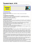
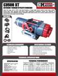
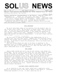
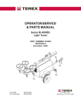
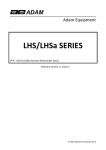
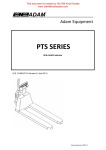
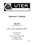
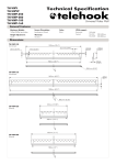
™
Service
Bishamon Industries Corporation
5651 E. Francis St.
Ontario, CA. 91761
(909) 390-0055 (800) 231-3187
PATENT PENDING
Vision Series Service Manual
Copyright © 2000, Bishamon Industries Corporation
All Rights Reserved
Table of Contents
Contents
Page
Getting Started . . . . . . . . . . . . . . . . . . . . . . . . . . . . . . . . . . . . . . . . . . . . . . . . . . . . . . . . . . . . . . . . . . . . .1
Inspection . . . . . . . . . . . . . . . . . . . . . . . . . . . . . . . . . . . . . . . . . . . . . . . . . . . . . . . . . . . . . . . . . . . . . . . . .1
Safety Definitions. . . . . . . . . . . . . . . . . . . . . . . . . . . . . . . . . . . . . . . . . . . . . . . . . . . . . . . . . . . . . . . . . . .1
General Dangers, Warnings, and Cautions. . . . . . . . . . . . . . . . . . . . . . . . . . . . . . . . . . . . . . . . . . . . . .1
Responsibilities of Owners/Users . . . . . . . . . . . . . . . . . . . . . . . . . . . . . . . . . . . . . . . . . . . . . . . . . . . . .4
Specifications. . . . . . . . . . . . . . . . . . . . . . . . . . . . . . . . . . . . . . . . . . . . . . . . . . . . . . . . . . . . . . . . . . . . . .4
Specification Drawing . . . . . . . . . . . . . . . . . . . . . . . . . . . . . . . . . . . . . . . . . . . . . . . . . . . . . . . . . . . . . . .5
Recommended Floor Area . . . . . . . . . . . . . . . . . . . . . . . . . . . . . . . . . . . . . . . . . . . . . . . . . . . . . . . . . . .6
Functional Description . . . . . . . . . . . . . . . . . . . . . . . . . . . . . . . . . . . . . . . . . . . . . . . . . . . . . . . . . . . . . .7
Maintenance Catch Operating Instructions . . . . . . . . . . . . . . . . . . . . . . . . . . . . . . . . . . . . . . . . . . . . .7
Installation . . . . . . . . . . . . . . . . . . . . . . . . . . . . . . . . . . . . . . . . . . . . . . . . . . . . . . . . . . . . . . . . . . . . . . . .8
Lift Operating Instructions . . . . . . . . . . . . . . . . . . . . . . . . . . . . . . . . . . . . . . . . . . . . . . . . . . . . . . . . . .10
Raising the Lift Platform . . . . . . . . . . . . . . . . . . . . . . . . . . . . . . . . . . . . . . . . . . . . . . . . . . . . . . .10
Loading / Unloading the Lift Platform . . . . . . . . . . . . . . . . . . . . . . . . . . . . . . . . . . . . . . . . . . . .10
Lowering the Lift Platform . . . . . . . . . . . . . . . . . . . . . . . . . . . . . . . . . . . . . . . . . . . . . . . . . . . . .11
Routine Maintenance. . . . . . . . . . . . . . . . . . . . . . . . . . . . . . . . . . . . . . . . . . . . . . . . . . . . . . . . . . . . . . .11
Daily Inspection . . . . . . . . . . . . . . . . . . . . . . . . . . . . . . . . . . . . . . . . . . . . . . . . . . . . . . . . . . . . . .11
Monthly Inspection and Maintenance . . . . . . . . . . . . . . . . . . . . . . . . . . . . . . . . . . . . . . . . . . . .12
Changing the Hydraulic Fluid . . . . . . . . . . . . . . . . . . . . . . . . . . . . . . . . . . . . . . . . . . . . . . . . . . .13
Cylinder Seal Replacement. . . . . . . . . . . . . . . . . . . . . . . . . . . . . . . . . . . . . . . . . . . . . . . . . . . . .15
Trouble Shooting . . . . . . . . . . . . . . . . . . . . . . . . . . . . . . . . . . . . . . . . . . . . . . . . . . . . . . . . . . . . . . . . . .15
Electrical Schematics . . . . . . . . . . . . . . . . . . . . . . . . . . . . . . . . . . . . . . . . . . . . . . . . . . . . . . . . . . . . . .16
Hydraulic Schematic . . . . . . . . . . . . . . . . . . . . . . . . . . . . . . . . . . . . . . . . . . . . . . . . . . . . . . . . . . . . . . .18
Replacement Parts . . . . . . . . . . . . . . . . . . . . . . . . . . . . . . . . . . . . . . . . . . . . . . . . . . . . . . . . . . . . . . . .18
Exploded Parts Drawing and Parts List
Vision Single Cylinder Lift Exploded View . . . . . . . . . . . . . . . . . . . . . . . . . . . . . . . . . . . . . . . . . . . . .19
Vision Single Cylinder Lift Parts List. . . . . . . . . . . . . . . . . . . . . . . . . . . . . . . . . . . . . . . . . . . . . . . . . .21
Vision Dual Cylinder Lift Exploded View. . . . . . . . . . . . . . . . . . . . . . . . . . . . . . . . . . . . . . . . . . . . . . .24
Vision Dual Cylinder Lift Parts List . . . . . . . . . . . . . . . . . . . . . . . . . . . . . . . . . . . . . . . . . . . . . . . . . . .26
Vision Single Cylinder Hydraulic Exploded View. . . . . . . . . . . . . . . . . . . . . . . . . . . . . . . . . . . . . . . .29
Vision Single Cylinder Hydraulic Parts List . . . . . . . . . . . . . . . . . . . . . . . . . . . . . . . . . . . . . . . . . . . .30
Vision Dual Cylinder Hydraulic Exploded View . . . . . . . . . . . . . . . . . . . . . . . . . . . . . . . . . . . . . . . . .31
Vision Dual Cylinder Hydraulic Parts List. . . . . . . . . . . . . . . . . . . . . . . . . . . . . . . . . . . . . . . . . . . . . .32
Vision Electrical Exploded View . . . . . . . . . . . . . . . . . . . . . . . . . . . . . . . . . . . . . . . . . . . . . . . . . . . . .33
Vision Electrical Parts List . . . . . . . . . . . . . . . . . . . . . . . . . . . . . . . . . . . . . . . . . . . . . . . . . . . . . . . . . .34
List of Figures
Fig. 1 - Safety Warning Label Locations . . . . . . . . . . . . . . . . . . . . . . . . . . . . . . . . . . . . . . . . . . . . . . .3
Fig. 2 - Lift Specification Drawing . . . . . . . . . . . . . . . . . . . . . . . . . . . . . . . . . . . . . . . . . . . . . . . . . . . .5
Fig. 3 - Recommended Floor Area . . . . . . . . . . . . . . . . . . . . . . . . . . . . . . . . . . . . . . . . . . . . . . . . . . . .6
Fig. 4 - Maintenance Catch Details . . . . . . . . . . . . . . . . . . . . . . . . . . . . . . . . . . . . . . . . . . . . . . . . . .7
Fig. 5 - Installation Components. . . . . . . . . . . . . . . . . . . . . . . . . . . . . . . . . . . . . . . . . . . . . . . . . . . .8
Fig. 6 - Handling the Vision Lift. . . . . . . . . . . . . . . . . . . . . . . . . . . . . . . . . . . . . . . . . . . . . . . . . . . . .9
Fig. 7 - Anchor Bolt Detail . . . . . . . . . . . . . . . . . . . . . . . . . . . . . . . . . . . . . . . . . . . . . . . . . . . . . . . .10
Fig. 8 - Hand Control Operation . . . . . . . . . . . . . . . . . . . . . . . . . . . . . . . . . . . . . . . . . . . . . . . . . . .10
Fig. 9 - Foot Control Operation . . . . . . . . . . . . . . . . . . . . . . . . . . . . . . . . . . . . . . . . . . . . . . . . . . . .10
Fig. 10 - Hydraulic Fluid Drain Detail . . . . . . . . . . . . . . . . . . . . . . . . . . . . . . . . . . . . . . . . . . . . . . . .13
Fig. 11 - Cylinder Hydraulic Fluid Removal Detail. . . . . . . . . . . . . . . . . . . . . . . . . . . . . . . . . . . . . .14
Fig. 12 - 115 Volt, Single Phase Electrical Schematic . . . . . . . . . . . . . . . . . . . . . . . . . . . . . . . . . . 16
Fig. 13 - 230 Volt, Single Phase Electrical Schematic . . . . . . . . . . . . . . . . . . . . . . . . . . . . . . . . . . 16
Fig. 14 - 230 Volt, Three Phase Electrical Schematic . . . . . . . . . . . . . . . . . . . . . . . . . . . . . . . . . . .17
Fig. 15 - 460 Volt, Three Phase Electrical Schematic . . . . . . . . . . . . . . . . . . . . . . . . . . . . . . . . . . .17
Fig. 16 - Hydraulic Schematic . . . . . . . . . . . . . . . . . . . . . . . . . . . . . . . . . . . . . . . . . . . . . . . . . . . . . .18
List of Tables
Table 1 - Operating Temperature / Recommended Hydraulic Fluid . . . . . . . . . . . . . . . . . . . . . . . 14
Date Placed in Service ______________________________________________
Serial Number______________________________________________________
Dealer ____________________________________________________________
GETTING STARTED
PLEASE READ THIS MANUAL CAREFULLY BEFORE USING THE Vision ™ Scissor Lift Table. The safety of all
persons installing, using or servicing the Vision™ lift table is of utmost importance to Bishamon. The Vision™ lift
is capable of supporting heavy loads and is capable of causing SEVERE PERSONAL INJURY if used improperly
or if certain safety precautions are not taken. When properly used and maintained, the Vision™ lift will provide
many years of safe, trouble free service. If you have any questions about any of the instructions in this manual or
about the use of this product, PLEASE contact your DEALER or Bishamon Industries Corporation.
Vision™ is a trademark of Bishamon Industries Corporation. Throughout this service manual the Vision™ scissor
lift table may be referred to as the “lift table” or the “lift”.
INSPECTION
IMMEDIATELY upon receipt of the lift table remove all the packing and strapping material and visually inspect the
unit for damage. Any damage to the unit MUST BE NOTED on the delivery receipt. After the preliminary
inspection is conducted, the unit should be thoroughly inspected for any concealed damage that was not readily
apparent during the preliminary inspection. Any concealed damage found that was not noted on the delivery
receipt should be IMMEDIATELY reported in writing TO THE DELIVERING CARRIER.
SAFETY DEFINITIONS
Bishamon uses the following system to identify the degree of risk associated with hazards and unsafe practices:
DANGER -
Immediate hazard which will result in SEVERE PERSONAL INJURY or DEATH.
WARNING -
Hazard or unsafe practice which could result in SEVERE PERSONAL INJURY or DEATH
and PROPERTY DAMAGE.
CAUTION -
Hazard or unsafe practice which could result in MINOR PERSONAL INJURY and
PROPERTY DAMAGE.
GENERAL DANGERS, WARNINGS, AND CAUTIONS
DANGER
READ THIS MANUAL COMPLETELY BEFORE USING. THOROUGHLY UNDERSTAND AND FOLLOW ALL
SAFETY INSTRUCTIONS.
A falling lift table can cause SEVERE PERSONAL INJURY or DEATH. NEVER go under the platform until the
load is removed and the scissor mechanism is secured in the raised position with the maintenance catches.
The maintenance catches have been designed for use only when the lift is UNLOADED. NEVER place any load
on the platform with the maintenance catches engaged. SEVERE PERSONAL INJURY or DEATH and
PROPERTY DAMAGE could result.
NEVER sit, stand, or ride on the platform. Moving components could cause loss of balance. SEVERE
PERSONAL INJURY or DEATH could result.
The lift’s electrical circuits use voltages which can cause SEVERE PERSONAL INJURY or DEATH. DO NOT
work with the electrical components unless you are a QUALIFIED ELECTRICIAN.
The lift’s electrical components can create sparks. DO NOT install the lift in an area where potentially explosive
dusts, gases, or vapors may be present. Failure to comply may result in an explosion and cause SEVERE
PERSONAL INJURY or DEATH.
1
Vision
WARNING
The Vision™ lift table is designed for use with stable uniformly distributed loads on a solid level floor. DO NOT
concentrate the load at one point on the platform or pallet. ALWAYS uniformly distribute each layer of load over
the supporting surface. DO NOT use the lift for any purpose other than its intended use.
DO NOT install the Vision™ lift table on an unlevel or soft surface. The lift base frame must be supported along
its entire length and width. Failure to completely support the base frame could result in damage to the lift.
DO NOT use the lift table with an unstable, unbalanced, or loosely stacked load. Unbalanced loads may become
unstable and fall. SEVERE PERSONAL INJURY and PROPERTY DAMAGE could result.
DO NOT overload the lift table. ALWAYS stay within the designated capacity ratings. SEVERE PERSONAL
INJURY and PROPERTY DAMAGE could result.
SHEARING HAZARD. ALWAYS keep hands and feet clear of the scissor mechanism and all moving
components. DO NOT put hands or fingers under the platform when in use. SEVERE PERSONAL INJURY
could result.
CRUSHING HAZARD. ALWAYS keep hands and feet clear of all moving components. DO NOT put feet on the
base frame when in use. SEVERE PERSONAL INJURY could result.
PINCH POINT HAZARD. ALWAYS keep feet, hands, and fingers away from the underside of the platform and all
moving components. SEVERE PERSONAL INJURY could result.
DO NOT change the relief valve setting. The relief valve is installed to protect the operator and the lift table.
Changing the relief valve setting may cause the lift to suddenly fall. SEVERE PERSONAL INJURY and
PROPERTY DAMAGE could result.
NEVER leave the loaded lift table unattended unless the platform is in the fully lowered position.
ALL lift servicing must be performed by qualified personnel only. Unauthorized modifications to the lift table, its
hydraulic power unit, or its control system may compromise the performance and safety of the system. UNDER
NO CIRCUMSTANCES should you attempt any repair or service that is not covered in this manual.
The release of fluids under high pressure can cause SEVERE PERSONAL INJURY. Before servicing the lift,
ALWAYS remove the entire load, engage the maintenance catches, and RELEASE THE HYDRAULIC
PRESSURE.
ALWAYS ensure all safety warning labels are in place and legible. If not, remove the lift table from service and
replace the required labels. Refer to Figure 1 for label descriptions and locations.
ALWAYS securely anchor the base frame to the floor to ensure maximum stability.
CAUTION
DO NOT continue to operate the pump if a squealing noise is heard coming from the pump. The pressure relief
valve is operating. Continued use of the pump with the relief valve operating will cause permanent damage to the
pump. REDUCE the load to prevent the relief valve from operating.
Vision
2
DANGER
READ MANUAL
SHEAR HAZARD
NO RIDING
1. READ THE MANUAL COMPLETELY BEFORE USING AND THOROUGHLY UNDERSTAND AND FOLLOW ALL SAFETY
INSTRUCTIONS.
2. A falling lift table can cause SEVERE PERSONAL INJURY or DEATH. NEVER go under the platform until the load is removed and
the scissor mechanism is secured in the raised position with the maintenance devices.
3. The maintenance devices have been designed for use only when the lift is UNLOADED. NEVER place any load on the platform with
the maintenance devices engaged. SEVERE PERSONAL INJURY or DEATH and PROPERTY DAMAGE could result.
4. NEVER sit, stand or ride on the platform. Moving components could cause loss of balance. SEVERE PERSONAL INJURY or
DEATH could result.
CRUSH HAZARD
KEEP CLEAR
MEC\B2000447
USE MAINTENANCE
DEVICES
MAXIMUM LIFTING CAPACITY
2500 lbs
1,130 kgs
UNIFORMLY DISTRIBUTED LOADS
ALL LOADS MUST BE CENTERED FOR PROPER OPERATION
NEVER EXCEED CAPACITY RATINGS
MEC-B2001340
CAUTION
The electric motor for this
unit has an Intermittent
Duty Rating. Make sure the
frequency of operation
does not exceed on full lift
every two minutes.
WARNING
NEVER GO UNDER THE
PLATFORM UNTIL THE
LOAD IS REMOVED AND
THE SCISSOR MECHANISM
IS LATCHED.
MEC-B2000528
OIL VISCOSITY
RECOMMENDATIONS
MEC\B2001338
POWER SUPPLY
230V / 3PH / 60HZ
MEC-B2000630
Best performance of the pump can be obtained
by utilizing proper oil with a viscosity
range between 150-250 SUS @ 100º F (32-54
cSt @ 40ºC). Minimum viscosity at operating
temperature should be at least 60 S US (10
cSt). Maximum start-up viscosity at minimum
ambient temperature should not exceed
4000 S US (880 cSt). Maximum recommended
operating temperature of hydraulic oil is
150ºF (65º C).
Oil S hould be non-corrosive, have maximum
anti-wear properties, rust and oxidation
treatment, and be non-foaming.
Recommended list of oils for ambient
temperature range of -10º F to +100º F
(-23º C to + 38º C) are as follows:
1. Amoco Oil Co.-Rycon Oil -32, 46;
Amoco AW 32, 46
2. Cities Service Oil Co.-Citgo A /W Hyd.
Oil 32, 46; Citgo All Temp. Hyd. Oil
3. Chevron US A-C hevron EP Hyd. Oil 32,
46.
4. Fina Oil Co.-Fina A/W 32, 46; Fina
Automatic Transmission Fluid Dexron II
5. Gulf Oil Corporation-Gulf Harmony 32
A/W, 46 A/W.
6. Mobil Oil Corporation-DTE 15, 24, 25,
Mobile Fluid -300 Transmission Fluid.
7. Sentinel Lubricants Corp.-S entinel
SH-10 Hydraulic Oil.
8. Shell Oil Co.-Tellus Hyd. Oil 32, 46;
Tellus “T” Hyd. Oil 32, 46.
9. Texaco Inc.-Rando Oil Hyd. 32,46.
10. Union
76-X’Cel
A/W 46
(200)
NOTE:
DO NOT
USE
BRA KE FLUID
MEC-B2001337
WARNING
NO FOOT
Note: VIS-25-36 decals shown for reference only
Figure 1 - Safety Warning Label Locations
3
Vision
RESPONSIBILITIES OF OWNERS/USERS
It is the responsibility of the Owners/Users to:
1. Advise the DEALER or Bishamon Industries Corporation when deflection or creep is critical to the application.
2. Ensure the lift is inspected and maintained in proper working order in accordance with the
operation/maintenance instructions provided in this manual.
3. Ensure any lift not in safe operating condition such as, but not limited to, excessive leakage, missing rollers,
pins or fasteners, bent or cracked structural members, cut or frayed hydraulic lines, damaged or
malfunctioning controls or safety devices, etc. shall be removed from service until it is repaired to Bishamon’s
standards.
4. Ensure all repairs are made by qualified personnel in conformance with the instructions provided by
Bishamon Industries Corporation.
5. Ensure only trained and authorized personnel are permitted to operate the lift and that all operators
understand the operating instructions, safety rules, and hazards associated with this lift.
6. Ensure the lift is used in accordance with the guidelines provided in this manual.
7. Ensure modifications or alterations of any lift are made only with the written permission of Bishamon
Industries Corporation.
VISION SPECIFICATIONS
Lift Capacity
Lowered Raised
Platform Plaform
Travel
Weight
Height Height
Width Length
24 in. to 48 in.
48 in. to 72 in.
2500-36
2500LB
1134Kg
7 in.
178 mm
43 in.
1092 mm
36 in.
914 mm
610 mm to 1219 mm 1219mm to 1829mm
3500-36
3500LB
1588Kg
7 7/16 in.
189 mm
43 7/16 in.
1103 mm
36 in.
914 mm
24 in. to 48 in.
48 in. to 72 in.
610 mm to 1219 mm
1219mm to 1829mm
5000-36
5000LB
2268Kg
7 1/2 in.
191 mm
43 1/2 in.
1105 mm
36 in.
914 mm
24 in. to 48 in.
48 in. to 72 in.
24 mm to 1219 mm
1219mm to 1829mm
6500-36
6500LB
2948Kg
7 1/2 in.
191 mm
43 1/2 in.
1105 mm
36 in.
914 mm
24 in. to 48 in.
48 in. to 72 in.
610 mm to 1219 mm
1219mm to 1829mm
1500-48
1500LB
680Kg
7 3/8 in.
187 mm
55 3/8 in.
1407 mm
48 in.
1219 mm
30 in. to 48 in.
62 1/2 in. to 96 in.
762 mm to 1219 mm
1588mm to 2438mm
2500-48
2500LB
1134Kg
7 3/8 in.
187 mm
55 3/8 in.
1407 mm
48 in.
1219 mm
30 in. to 48 in.
62 1/2 in. to 96 in.
762 mm to 1219 mm
1588mm to 2438mm
3500-48
3500LB
1588Kg
7 1/2 in.
191 mm
55 1/2 in.
1410 mm
48 in.
1219 mm
30 in. to 48 in.
62 1/2 in. to 96 in.
762 mm to 1219 mm
1588 to 2438mm
5000-48
5000LB
2268Kg
7 1/2 in.
191mm
55 1/2 in.
1410 mm
48 in.
1219 mm
30 in. to 48 in.
62 1/2 in. to 96 in.
762 mm to 1219 mm
1588mm to 2438mm
6500-48
6500LB
2948Kg
7 3/4 in.
197 mm
55 3/4 in.
1416 mm
48 in.
1219 mm
30 in. to 48 in.
62 1/2 in. to 96 in.
762 mm to 1219 mm
1588mm to 2438mm
2500-24
2500LB
1134Kg
7 in.
178 mm
31 in.
787 mm
24 in.
610 mm
24 in. to 48 in.
41 in. to 60 in.
610 mm to 1219 mm
1041mm to 1524mm
3500-24
3500LB
1588Kg
7 1/8 in.
181 mm
31 1/8 in.
791 mm
24 in.
610 mm
24 in. to 48 in.
41 in. to 60 in.
610 mm to 1219 mm
1041mm to 1524mm
5000-24
5000LB
2268Kg
7 1/8 in.
181 mm
31 1/8 in.
791 mm
24 in.
610 mm
24 in. to 48 in.
41 in. to 60 in.
610 mm to 1219 mm 1041mm to 1524mm
6500-24
6500LB
2948Kg
7 1/8 in.
181 mm
31 1/8 in.
791 mm
24 in.
610 mm
24 in. to 48 in.
41 in. to 60 in.
610 mm to 1219 mm
1041mm to 1524mm
Vision
4
590LB
625LB
735LB
750LB
885 LB
895 LB
1030 LB
1050 LB
1060 LB
445 LB
455 LB
640 LB
655 LB
ADDITIONAL SPECIFICATIONS AND SPECIFICATION
DRAWING
SPECIFICATIONS:
1. Sound Pressure Level
<70dB(a)
2. Operating Environment
Indoors
3. Lighting Requirement
Good General Lighting
(See Table 1)
PLATFORM
LENGTH
BASE LENGTH
LOWERED
HEIGHT
PLATFORM
WIDTH
TRAVEL
RAISED
HEIGHT
4. Operating Temperature
BASE WIDTH
Vision Series
Figure 2 - Lift Specification Drawing
5
Vision
RECOMMENDED FLOOR AREA
Operating
Zone
39 inches
1 meter
39 inches
1 meter
Lift Table
Danger
Zone
39 inches
1 meter
39 inches
1 meter
Figure 3 - Recommended Floor Area
The lift table’s recommended floor area, shown in Figure 3, identifies the “Danger Zone” and the “Operating
Zone”. The Danger Zone is the area inside the base frame and under the platform structure. The recommended
Operating Zone is a distance of 39 inches (1 meter) extending beyond the danger zone on all sides.
DANGER
A falling lift table can cause SEVERE PERSONAL INJURY or DEATH. NEVER go under
the platform until the load is removed and the scissor mechanism is latched with the
maintenance catches. The maintenance catches have been designed for use only when
the lift is UNLOADED. NEVER place any load on the platform with the maintenance
catches engaged. SEVERE PERSONAL INJURY or DEATH and PROPERTY DAMAGE
could result.
Vision
6
FUNCTIONAL DESCRIPTION
Vision Series lift tables are versatile and heavy-duty. These electro-hydraulic scissor lift tables are designed and
manufactured to increase productivity and reduce worker strain. By lifting and accurately positioning the load,
Vision lifts eliminate unproductive lifting and stretching that ultimately leads to worker fatigue, injuries, and product
damage. They are well suited for handling a wide variety of products including work in progress, palletized loads,
containers, bins, tools, and dies.
Vision Lifts are available in 1500 lb, 2500 lb, 3500 lb, 5000 lb and 6500 lb capacities (1500 lb is only available in
the 48 inch vertical travel model) and 24 inch, 36 inch and 48 inch vertical travels. The platform position is
completely variable in height between the upper and lower travel limits. Lowered height is 7 inches to 7 ¾ inches
depending on the model (see Vision Specifications).
Depressing the “RAISE” control actuates the hydraulic power unit and directs hydraulic fluid to the piston side of a
single, single-acting cylinder. The cylinder rod extends and opens the scissor assembly, which in turn raises the
platform. Lowering is achieved by depressing the “LOWER” control actuating a solenoid valve at the hydraulic
power unit. Opening the valve allows hydraulic fluid to flow out of the cylinder and return to the reservoir. A
pressure compensated flow control valve within the power unit controls the lowering speed.
MAINTENANCE CATCH OPERATING INSTRUCTIONS
To Engage The Maintenance Catches:
1. Remove the entire load from the platform and raise the lift table to its fully raised position.
2. Move to the side of the lift. As detailed in Figure 4, rotate the maintenance catch until the catch arm engages
the outer scissor leg axle.
3. Move to the opposite side of the lift and repeat step 2 for the other catch arm. ALWAYS ensure BOTH catch
arms are engaged.
4. Slowly lower the lift by depressing the lowering control button or pedal. The lift will lower slightly until the
maintenance catches completely engage the axle. ALWAYS check the position of both maintenance catches
before going under the platform.
ENGAGED
DISENGAGED
Figure 4 - Maintenance Catch Details
To Disengage The Maintenance Catches:
1. Raise the platform to its fully raised position.
2. Move to the side of the lift and rotate the maintenance catch to its disengaged position (See Figure 4).
3. Repeat step two (2) for opposite side of the lift.
7
Vision
INSTALLATION
The Vision™ lift table is shipped on a pallet and only requires minor assembly before it is ready for use. Before
you begin, locate and identify the components detailed in Figure 5. These components will be referred to in the
installation procedures. Make sure you understand the function of each component before proceeding.
TOOLS REQUIRED
1. Banding or Strap Cutters
2. Drill Motor with ½” Concrete Drill Bit
3. 3/4" Box End Wrench
4. Hammer
HYDRAULIC
RESERVOIR
BREATHER
POWER CORD
BASE FRAME
ANCHOR PLATE
BASE
FRAME
GUARD
HAND CONTROL
Figure 5 - Installation Components
Power Cord - All Vision™ lift tables are supplied with a 12 ft power cord of the proper size and rating for the
hydraulic power unit.(NOTE: A power cord plug is not supplied with the lift due to the many different types of
electrical receptacles and electrical installation options. A QUALIFIED ELECTRICIAN must install an electrical
plug of the proper style and rating on the power cord or hard-wire the cord to an electrical panel. All electrical
installation aspects must conform to the National Electrical Code or the proper governing agency for the area.)
Hydraulic Reservoir Breather - All Vision™ lift tables are supplied with hydraulic fluid in the reservoir. The
breather is located on top of the reservoir and must be removed to check the fluid level or to add hydraulic fluid.
Base Frame Guard - All Vision™ lift tables are supplied with an electrical base frame guard. The guard, when
depressed, prevents the lift from lowering.
Base Frame Anchor Plate - Four pre-drilled base frame anchor plates are provided to secure the lift to the floor or
installation surface.
Hand Control - All Vision™ lift tables are supplied with a hand control (or optional foot switch) that is used to raise
or lower the lift.
Vision
8
DANGER
The lift’s electrical circuits use voltages which can cause SEVERE PERSONAL INJURY or
DEATH. DO NOT work with the electrical components unless you are a QUALIFIED
ELECTRICIAN.
Installation Instructions
1. Using a fork lift or similar equipment, move the palletized lift to the location it is to be installed. The installation
area should be clean and have good general lighting.
2. Next, using the strap cutter, remove the bands securing the lift to the pallet. Remove all packing material and
place it off to the side.
3. Locate the 12 ft power cord attached to the lift’s base frame. A power plug is not supplied with the lift due to
the many different types of electrical receptacles and electrical installation options. Next, have a QUALIFIED
ELECTRICIAN install an electrical plug of the proper style and rating on the power cord or hard-wire cord to
an electrical panel. Ensure both the power source and receptacle have the proper voltage and amperage
rating for the lift’s electric motor. Finally, insert the plug into the receptacle and/or turn on the supply voltage
to the unit.
4. Locate the lift’s hand control (See Figure 8) and depress the “RAISE” button to raise the lift to its maximum
raised height. In the case of a foot control (See Figure 9), depress the “RAISE” pedal to raise the lift.
Following the Maintenance Catch Operating Instructions on page 7, engage the maintenance catch on each
side of the lift. DO NOT lower the lift to engage the catches at this time.
5. Using a forklift, position the forks under
the platform structure, as detailed in
Figure 6. Proper care should be
exercised while using the fork lift as to not
damage the lift. Lift the Vision™ lift off
the pallet. Next, remove the pallet and
place if off to the side. Position the lift in
the desired location. Use care not to
damage the lift’s power cord or control
cord.
NOTE: The Vision™ base frame MUST
be secured to the floor for maximum
stability. Contact your Dealer or
Bishamon Industries Corporation if you
have any questions regarding the proper
installation of the lift. Complete steps 6
and 7 to secure the lift to the floor.
6. The lift table’s base frame has four (4) 5/8
in. holes for lagging the unit securely to
the floor. Using the four (4) holes as a
template, drill a ½ in. diameter hole, 3 in.
minimum depth at each location. The
floor surface should be level and the
drilled holes perpendicular to the floor. If
required, shift the position of the lift with a
forklift to allow room for drilling, then drill.
When complete, reposition the lift.
7. As detailed in Figure 7, prepare the ½ in.
diameter x 4 in. long anchor bolts (USE
Figure 6 - Handling the Vision Lift
type SUP-R-STUD #26-12400 or
equivalent) by assembling the washer
and nut on the anchor bolt. The nut should be screwed onto the anchor bolt approximately ½ the nut height.
Drive the assembled anchor through the mounting holes into the concrete until the washer is flush with the top
of the anchor plate. Expand the anchor shield by tightening the nut as required for tight fit, approximately
three (3) to five (5) turns. Repeat step 7 for the remaining anchors. (NOTE: Make sure the underside of the
base frame surface is fully supported, use shims or concrete grout if necessary.)
9
Vision
8. Check the base frame guard to ensure it
floats freely on top of the base frame and
that no obstruction exists.
9. Disengage the maintenance catches and run
the lift up and down several times to remove
any air that may have been trapped in the
hydraulic system due to shipping.
10. Check the operation of the base frame
guard. To do so, raise the lift to its maximum
height. Slightly depress the base frame
guard, then depress the lower push button or
pedal. The lift should not lower until the
guard is released.
11. The Vision™ lift is now ready for operation.
Refer to the following section for complete
operating instructions.
Figure 7 - Anchor Bolt Detail
LIFT OPERATING INSTRUCTIONS
Raising the Lift Platform
1. Before raising the platform, BE SURE that all others are well clear of the lift. If the platform is loaded,
RECHECK the position and condition of the load.
2. As shown in Figures 8 and 9, depress the “Raise” button or pedal to raise the platform to a convenient
position. CONTINUOUSLY WATCH the condition of the load as the platform is raised. If the load appears to
be shifting STOP, lower the platform and adjust the load.
Loading / Unloading the Lift Platform
1. Check the load or component weight to ensure the total load does not exceed the capacity of the lift. Refer to
the capacity decal on the side of the lift platform.
2. If required, raise or lower the platform to a convenient working height.
3. Uniformly distribute the load over the platform or supporting surface and ensure the load is tightly stacked.
RA
ISE
Figure 8 - Hand Control Operation
Vision
LO
WE
R
Figure 9 - Foot Control Operation
10
WARNING
DO NOT concentrate the load at one point on the pallet or platform. ALWAYS uniformly
distribute each layer of load over the supporting surface.
DO NOT use the lift table with an unstable, unbalanced or loosely stacked load.
Unbalanced loads may become unstable and fall. SEVERE PERSONAL INJURY and
PROPERTY DAMAGE could result.
DO NOT overload the lift table. ALWAYS stay within the designated capacity ratings.
SEVERE PERSONAL INJURY and PROPERTY DAMAGE could result.
Lowering the lift Platform
1. Before lowering the platform, BE SURE that you, as well as all others, are well clear of the lift. If the platform
is loaded, RECHECK the position and condition of the load.
2. Depress the lowering button or pedal (see Figures 8 and 9) to lower the lift platform. CONTINUOUSLY
WATCH the condition of the load as the platform is lowering. If the load appears to be shifting, STOP and
adjust the load.
ROUTINE MAINTENANCE
The Vision™ lift table is designed to provide years of trouble free service and requires very little maintenance.
However, a routine inspection and maintenance program will prevent costly replacement of parts and/or
downtime. All service should be performed by a qualified service person who has an understanding of lift
equipment and electrical and hydraulic diagrams. This person should be thoroughly familiar with the operation
and use of this type of equipment.
DANGER
A falling lift table can cause SEVERE PERSONAL INJURY or DEATH. NEVER go under
the platform until the load is removed and the scissor mechanism is secured in the raised
position with the maintenance catches.
The maintenance catches have been designed for use only when the lift is UNLOADED.
NEVER place any load on the platform with the maintenance catches engaged. SEVERE
PERSONAL INJURY or DEATH and PROPERTY DAMAGE could result.
Daily Inspection
1. Before use, visually inspect the lift for worn, damaged, or broken components. (NOTE: A lift with a bellows
option must have the bellows strapped up in order to perform the following visual inspections.) If any of these
conditions exist, REMOVE the lift from service and contact a qualified service person to repair or replace
these items at once.
2. Raise the platform and visually inspect the hydraulic components (i.e. pump, hoses, fittings, and cylinder) for
fluid leakage. If fluid leakage exists, REMOVE the lift from service and contact a qualified service person.
3. Check the operation of the base frame guard by raising the unloaded lift to its maximum height. Slightly
depress the guard and then depress the lowering button or pedal. The lift should NOT lower until the guard is
released. If the lift lowers while the guard is depressed, REMOVE the lift from service and contact a qualified
service person to have this problem repaired at once.
4. Check the condition of the warning labels. The warning labels are for the safety of the operator. If the labels
are worn, missing, or unreadable, REPLACE them before placing the lift back in service.
11
Vision
WARNING
ALL lift servicing must be performed by qualified personnel only. Unauthorized
modifications to this lift may compromise the performance and safety of the system.
UNDER NO CIRCUMSTANCES should you attempt any repair or service that is not
covered in the service manual or authorized by Bishamon Industries Corporation.
The release of hydraulic fluid under high pressure can cause SEVERE PERSONAL
INJURY. Before servicing the lift, ALWAYS remove the load, engage the maintenance
catches, and RELEASE THE HYDRAULIC PRESSURE.
ALWAYS ensure all safety warning labels are in place and legible. If not, remove the lift
from service and replace the required labels.
Monthly Inspection and Maintenance
1. Inspect snap rings and roll pins at all pivot shaft and axle locations. If a snap ring or roll pin is not in place
and/or secure, REMOVE the lift from service and contact a qualified service person to replace or repair these
items at once.
2. Inspect the scissor rollers, cylinder pivot pins, cylinder bushings, scissor pivot pins, and scissor bushings for
signs of wear. If worn, REMOVE the lift from service and contact a qualified service person to replace or
repair these items at once. All pivot locations have lifetime lubricated bushings therefore they do not need
grease or lubrication.
3. Inspect the removable scissor hinge blocks for tightness. Each block has two (2) socket head cap screws
that secure the block to the base frame or the platform. Check the screws for tightness. Each screw should
be tightened to 38 ft-lbs of torque. If loose, REMOVE the lift from service and contact a qualified service
person to have these screws tightened to the proper torque.
4. Inspect the hydraulic power unit and cylinder for signs of leakage. The presence of a small amount of fluid
around the cylinder rod is normal. However, fluid flowing from around the top of the cylinder head cap
indicates worn seals. If this condition exists, REMOVE the lift from service and contact a qualified service
person to have the cylinder seals replaced at once .
5. Inspect the flexible hydraulic lines for abrasion and wear. If these conditions exist, REMOVE the lift from
service and contact a qualified service person to have these flexible hydraulic lines replaced at once.
6. Inspect the hydraulic line connections for tightness. If loose, REMOVE the lift from service and contact a
qualified service person to tighten these connections as necessary.
7. Check the level and appearance of the hydraulic fluid. To do so, raise the unloaded platform and engage the
maintenance catches (See Maintenance Catch Operating Instructions on page 7). Remove the breather on
the top of the reservoir (Refer to Figure 5). Using a dip stick, check the fluid level from the top of the
reservoir. The proper fluid level is between 2 ½ - 3 inches below the top of the reservoir breather port with the
lift in the raised position. If required, add fluid to the reservoir. CAUTION: DO NOT overfill the reservoir or
fluid will be forced out the breather when lift is collapsed. Check the condition of the fluid, it should appear
light in color. The fluid should be changed if the color has darkened or if it feels gritty. Replace the reservoir
breather.
Vision
12
Changing the Hydraulic Fluid (Every 12 Months)
Change the hydraulic fluid every 12 months of service or more often if conditions warrant. The frequency of
fluid change will depend upon the general working conditions, severity of use, and the overall cleanliness and
care given to the lift.
Figure 10 - Hydraulic Fluid Drain Detail
1. To change the hydraulic fluid, raise the unloaded platform to its maximum height and engage the
maintenance catches (See Maintenance Catch Operating Instructions on page 7). CAUTION: Be sure to
lower the lift onto the maintenance catches. Depress and hold the lowering button or pedal for several
seconds to allow any residual hydraulic pressure to diminish.
2. Disconnect the lift from the power source. As detailed in Figure 10, remove the two (2) screws that secure
the Hose Hold Down (VIS-B7001354), remove the Hose Hold Down, and re-install the screws to secure the
motor junction box plate (Note: The three phase power unit does not use the Hose Hold Down). Remove the
two (2) 3/8 –16 x 1inch long bolts (MEC-B2001379) that secure the power unit to the motor mount bracket.
Raise the power unit approximately 2 ½ inches and insert a shallow pan (approximately 8 in. x 14 in. x 2 in.
deep) under the power unit such that fluid drained from the pressure line fitting (HYD-B4001034) and return
line fitting (HYD-B4001033) will drain into the pan. (NOTE: The pan should be strong enough to support the
weight of the power unit.) Next, remove the cylinder return line from the reservoir by disconnecting the hose
fitting (HYD-B4000191) from the return line fitting (HYD-B4001033) and remove the cylinder pressure line
from the pump housing by disconnecting it from the pressure line fitting (HYD-B4001034). Allow the
reservoir, pump, return line, and pressure line to drain into the pan. It may be necessary to tip the power unit
slightly on its side to completely drain the reservoir.
3. Carefully remove the pan from under the power unit and place it along the left side the of the base (the side
closest to the hydraulic lines). Lay the power unit in the base frame, but do not replace the motor attachment
bolts at this time.
4. The old hydraulic fluid must now be removed from the cylinder(s). As detailed in Figure 11, place the end of
the pressure line and the end of the reservoir return line in the pan.
5. For single cylinder models: remove the roll pin (MEC-B2000422) that retains the upper cylinder pin
(VIS-B5002352). Remove the upper cylinder pin (VIS-B5002352) and tilt the cylinder to a vertical position.
For dual cylinder models: remove the bolt (MEC-B2000029) and washers that retain the upper cylinder pin
(VIS-B5002241 for 36 and 24 inch vertical travel models or VIS-B5002242 for the 48 inch vertical travel
model) and tilt the cylinders to a vertical position. While vertical, push the cylinder(s) rod down completely to
13
Vision
6.
7.
8.
9.
10.
purge the fluid from the piston side. Next, pull the
cylinder(s) rod up completely to purge any remaining
fluid from the rod side. Finally, push the cylinder(s)
rod down completely.
Clean the ends of both hydraulic lines and reconnect
them to the power unit. Ensure both hose
connections are tight. Reposition the power unit in
the base frame and replace the two (2) bolts that
secure the power unit to the lift’s base frame.
Tighten securely. Replace the Hose Hold Down.
(NOTE: The old hydraulic fluid is considered
hazardous waste and should be handled and
disposed of properly. Carefully remove the pan and
properly dispose of the remaining hydraulic fluid.)
Completely fill (approximately 1inch below the filler
port) the reservoir with the correct hydraulic fluid.
Refer to Table 1 for the proper fluid selection.
Clean all spilled fluid and thoroughly inspect the lift
and all hydraulic components. Reconnect the power
cord to the power supply and jog the motor by
pressing the “RAISE” button or pedal to prime the
pump and begin to extend the hydraulic cylinder.
Slowly extend the cylinder such that when the
cylinder rod is fully extended, the fluid level in the
reservoir is between 2 ½ - 3 inches from the top of
the reservoir breather port and the rod end cross
tube lines up with the holes in the cylinder mounting
clevis. Replace the upper cylinder pin.
Raise the lift to its maximum height and disengage
the maintenance catches. Completely raise and
Figure 11 - Cylinder Hydraulic Fluid
lower the lift eight (8) to ten (10) times to fill the rod
Removal Detail
end reservoir and remove any trapped air from the
hydraulic system.
Completely raise the lift and engage the maintenance catches. Recheck the fluid level as detailed in the
“Monthly Inspection and Maintenance” section. The lift is now ready for use.
Fluid Type
Manufacturer
Fluid Temperature Range ºF
DTE LIGHT
MOBILE
+40 - +150
DTE 13
MOBILE
0 - +160
SAE 10
PENNZOIL, MOBILE, ETC
0 - +150
SAE10W30
PENNZOIL, MOBILE, ETC
+20 - +170
SAE 20
PENNZOIL, MOBILE, ETC
+30 - +170
MIL 5606
(Aircraft Hydraulic Fluid)
PENNZOIL, MOBILE, ETC
-30 - +75
Table 1 - Operating Temperature / Recommended Hydraulic Fluid
Vision
14
Cylinder Seal Replacement
In the event the pump or cylinder seals are leaking, detailed instructions and replacement part kits are available.
Contact the DEALER or Bishamon Industries Corporation to obtain service kits and instructions for these items.
Trouble Shooting
Problem
Platform will not raise.
(Pump will not run)
Platform will not raise.
(Pump will run)
Platform will not remain
elevated.
Platform will not lower.
Platform lowers too
slowly.
Pump motor
continuously runs.
Cause
Solution
Power disconnected.
Verify that power source is applied.
Open wire in electric circuit.
Check for faulty wiring.
No hydraulic fluid in reservoir.
Fill reservoir.
Load too heavy (relief valve operating).
Reduce load.
Lowering solenoid valve stuck open.
Clean or replace valve.
Check for faulty wiring.
Lowering solenoid valve stuck open.
Clean or replace valve.
Check for faulty wiring.
Toe guard switch is activated.
Platform or scissor obstruction.
Lowering solenoid valve not opening.
Obstruction in flow limiting valve.
Relay malfunction.
Remove obstruction.
Remove obstruction or reposition lift.
Check for faulty wiring.
Clean / Flush flow limiting valves.
Replace relay.
Obstruction in solenoid valve.
Clean / Flush solenoid valve.
Obstruction in flow limiting valve.
Clean / Flush flow limiting valves.
Motor contactor frozen closed.
Replace motor contactor.
Wiring malfunction.
Check for faulty wiring.
Cylinder seals worn or damaged.
Repack cylinder.
Valves, fittings or hoses loose.
Tighten valves, fittings or hoses.
Reservoir over-filled with fluid.
Drain excess fluid.
Hose or fitting loose.
Tighten hose or fitting.
Pump piston seal worn or damaged.
Repack pump.
Cylinder leaking.
Pump leaking
15
Vision
M
1
. 29
3200
PSI
1
2.0
GPM
NOTE:
1. SINGLE CYLINDER SCHEMATIC SHOWN
2. PUMP DISPLACEMENT IS .065 CU IN/REV FOR THE 115V MOTOR.
Figure 16 - Hydraulic Schematic
Replacement Parts
Bishamon has carefully selected the components used in the manufacture of the Vision™ scissor lift tables. In
the event replacement parts are required, ALWAYS use genuine Vision™ components provided by Bishamon.
These parts can be obtained from your Bishamon DEALER or by contacting Bishamon Industries Corp.
Vision
18