1
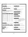
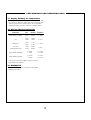
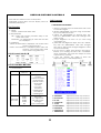
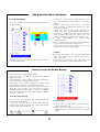
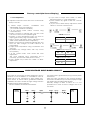
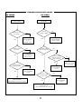
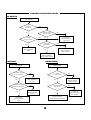
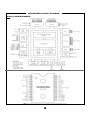
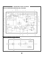
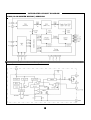
MTG-XX02XT/XN Publication A. Issue 1
SERVICE AND OPERATION MANUAL
MTG- XX02XT/XN
OPEN FRAME XVGA COLOR MONITORS
MTG-1702XT/XN : 17INCH, FST
MTG-1902XT/XN : 19INCH, FST
Information in this publication current as of Jun, 2003.
Information subject to change as display technology advance.
This publication produced by TOVIS Engineering Division.
This monitor has been designed and manufactured to deliver high performance video. For continued peak Performance
use safe operation, only high quality TOVIS replacement parts or their exact specified Equivalent When servicing.
SAFETY PRECAUTIONS AND WARNINGS
Service Warning
CRT Warning
This display contains HIGH VOLTAGE capable
of delivering LETHAL quantities of energy.
Service should only be attempted by trained
personnel familiar with the potential dangers
inherent with voltage equipment.
All picture tubes used in TOVIS monitors are
equipped with an integral implosion protection
system.
The picture Tube is, however, a highly evacuated
component whose outside surfaces are subject to
strong external forces. Care must be exercised so
as not to bump or scratch the tube during
installation or servicing as this may cause the tube
to implode resulting in possible personal injury and
property damage. Shatter-proof goggles must be
worn by Individuals while handling the CRT or
installing the display in the cabinet. Do not handle
The CRT by the neck.
Safety Related Component Warning
Certain components used in TOVIS color
monitors are critical for safe operation of the
display. These parts Number are marked by
(
) in the parts list and on the schematic
diagram it is essential that these Safety critical
components be replaced only with exactly
specified components to prevent the
Possibility of excessive X-radiation emission,
electrical
shock,
fire,
or
premature
component failure.
Modifying the original design without written
approval from TOVIS is expressly forbidden, will
void the original Parts and labor warranty, and
may result in creating a hazardous situation.
1. Always ensure the high voltage at the anode cap
is fully discharged prior to handling or service.
2. Replace picture tube only with same type and
number.
Product Safety and Service Guidelines
1. Service should be performed only after reading all
of the warnings and precautions in this manual
and as Labeled on the CRT and chassis.
X-RADIATION WARNING
2. Where a short circuit has occurred, replace all
components
that
indicate
evidence
of
overheating or poor Connection on all plastic
connectors.
COMPONENTS WHICH MAY AFFECT POTENTIAL
EXCESS EMISSION OF X-RADIATION IN THE
HORIZONTAL DEFLECTION AND HIGH VOLTAGE
CIRCUITS (INCLUDING THE PICTURE TUBE) ARE
TO BE USE ONLY TYPE AND RATING OF
REPLACEMENT COMPONENT AS SHOWN IN THE
PARTS LIST.
3. Inspect wiring for frayed leads and damaged
insulation when service is required, observe original
lead Dress is followed as from the factory,
especially in the high voltage circuitry area.
1. The only potential source of X-radiation
emission is the picture tube. When the high
voltage and horizontal deflection circuits are
operating correctly there is no possibility of
excess X- radiation emission. NEVER attempt
to modify these circuits.
4. All protective devices must be reinstalled per
original design.
2. Periodically check the high voltage with a
reliably calibrated meter for values not in
excess of Manufacturer’s recommendations.
See high voltage Shut-down Circuit, page 4,
for further details.
2
PERFORMANCE AND OPERATING DATA
1. Power Supply
6. Leakage Current
*Power Input: 100VAC ~ 254VAC, 50/60Hz
*Fuse Rating: 250V, 50T 3.15A
*Power Consumption:
Size
W(Max)
17”
100
To chassis ground, at 220VAC, 50Hz (Line/Neutral in
common)
- 0.195mA Maximum
19”
130
7. High Pot
Line/Neutral in common to secondary/chassis,
1500VAC 60Hz for 1 second
- 2.0mA Maximum, No Breakdown
2. Signal Input
*Video Input: Analog, Positive Signal (0.7V p-p)
*Horizontal Sync: TTL Level, Positive or Negative Pulse
*Horizontal Scan: 28KHz ~ 70KHz
*Vertical Input: TTL Level, Positive or Negative Pulse
*Vertical Scan: 40Hz ~ 160Hz
*Resolution-Mode
Hf
31KHz
Vf
70Hz
Resolution
720x400
H Range
28 ~ 32.9
V range
68 ~ 72
31KHz
60Hz
640x480
28 ~ 32.9
58 ~ 62
35KHz
86Hz
1024x768
33 ~ 35.9
84 ~ 88
38KHz
75Hz
640x480
36 ~ 40.9
73 ~ 77
38KHz
60Hz
800x600
36 ~ 40.9
58 ~ 62
47KHz
75Hz
800x600
41 ~ 51.9
73 ~ 77
48KHz
72Hz
800x600
41 ~ 51.9
70 ~ 74
48KHz
60Hz
1024x768
41 ~ 51.9
58 ~ 62
53KHz
85Hz
800x600
52 ~ 61.9
83 ~ 87
56KHz
70Hz
1024x768
52 ~ 61.9
68 ~ 72
60KHz
75Hz
1024x768
52 ~ 61.9
73 ~ 77
64KHz
60Hz
1280x1024
62 ~ 70
58 ~ 62
68KHz
85Hz
1024x768
62 ~ 70
83 ~ 87
8. Implosion Protection
- Provided by band and mounting lugs
9. Magnetic Shielding
- Internal
10. X-Radiation
- 0.50mR/hr Maximum
11. Mis-convergence
- Center : 0.30mm Maximum
- Corners : 0.45mm Maximum
12. Non-Linearity
Using a vertical and horizontal symmetrical cross
hatch pattern to equation for non-linearity will be
Non-linearity (%) = ((largest grid minus the smallest
grid) Divided by (largest grid plus
the smallest grid)) times 100.
- Standard Mode : 5% maximum
- Other Modes : 10% maximum
13. Temperature
3. Picture Tube
- Operating: 0° ~ 50°C
- Storage: -10°C ~ 75°C
- Humidity: 10% ~ 90%(Non-condensing)
The Cathode Ray Tube shall be a SAMSUNG Normal
& Dyna-Flat or equivalent
Size
17 FST
Dot Pitch
0.26mm
Phosphor
P22
P/N
M41QAR361X
19 FST
0.26mm
P22
M46QCE261X
4. Pincushion
- 5% Maximum (All Brightness)
14. Power Save Mode
Shall be initiated by holding the Vertical Sync input
Low (0.5V) and shall reduce the power to less than
20 Watts.
15. Degaussing
Automatic at power-up and software via control
Switch “SEL”
5. MTBF
- 20,000 Hours Minimum
16. Regulation (Static)
The horizontal and vertical size will change less than
2mm for a 25% white level abrupt luminance change.
3
PERFORMANCE AND OPERATING DATA
17. Display Stability for Temperature
The temperature is cycled from 25°C to 0°C, and
from 25°C to 50°C the video size and centering drift
will not exceed 5mm horizontally or 4mm vertically.
(Measured after a 20 min. warm-up period at 25°C)
18. Monitor Test Specifications
Parameter
Size
Normal
Tolerance
H/V
(0uA Beam Current)
17 FST
19 FST
26.0KV
27.0KV
+/- 500V
G2
17 FST
19 FST
530V
560V
+/- 10V
Brightness
17 FST
19 FST
0.4FL
0.5FL
+/- 0.3FL
Contrast
(10% Window Box)
17 FST
19 FST
60.0FL
60.0FL
+/- 5FL
White Balance(9300)
X: 0.281
Y: 0.311
+/- 0.015
+/- 0.015
White Balance(6500)
X: 0.313
Y: 0.329
+/- 0.015
+/- 0.015
*Test Mode: VGA 640 x 480(Fh: 31KHz, Fv: 60Hz)
*Signal: BSG-170 (BARO)
19. WARRANTY
Manufacturer warranty 2 years parts and labor.
(Except on C.R.T)
4
USER ADJUSTABLE CONTROLS
There are four switches on the control panel.
Adjustable controls allow the best display status for
individual preferences
OSD Controls
: User’s control.
A. BRIGHTNESS ADJUSTMENT
Key Function
1) Press the “MODE” key then Main-Menu OSD come
out as below Figure.
2) Search “BRIGHTNESS” sub-menu using “UP/DOWN”
key on the Main-Menu OSD.
3) Select the “BRIGHTNESS” by pressing “SEL” key.
Then The “BRIGHTNESS” OSD color changes from
yellow to red.
4) Adjust Brightness as much as you want using
“UP/DOWN” key.
5) After finish the Brightness adjust, Press the “MODE”
key then the “BRIGHTNESS” OSD color changes
from red to yellow and changed brightness value
saved automatically.
6) If you want to adjust other function (sub-menu),
Search your wanting sub-menu like “CONTRAST”
using “UP/DOWN” keys and then adjusts as same
way as item 3), 4) and 5).
7) Press the “MODE” key again to finish the
adjustment then the OSD disappeared.
① MODE
*MODE - Call the Main-Menu OSD.
② SEL/DEGAUSS
*SEL – Select the function (sub-Menu OSD) on the
Main- Menu OSD.
*DEGAUSS – Do degaussing in state that the OSD
isn’t displayed.
③ DOWN/UP
*When the Main-Menu is displayed, can search each
function using these keys.
*When the Sub-Menu is displayed (after select the
function), can change each state
of the screen using these keys.
O.S.D Control Sub-P.C.B
O.S.D CONTROL METHOD
1) Control items.
Adjustment
Method
Function
SUB PCB
OSD Control
Brightness
Contrast
Horizontal Position
Horizontal-Size
Vertical Position
Vertical-Size
Rotation
Pincushion
Trapezoid
Parallelogram
Pin balance
Parallelogram
MAIN PCB
VR control
VR301
VR501
VR502
VR503
FBT
Sub H-size
H.V Adjustment
ABL Adjustment
Sub-Bright
Focus and Screen
Location
B. CONTRAST
C. H.POSITION
D. H-SIZE
E. V.POSITION
F. V-SIZE
G. PINCUSHION
H. TRAPEZOID
I. PARALLELOG
J. PINBALANCE
5
Adjusted as same way as above
Adjusted as same way as above
Adjusted as same way as above
Adjusted as same way as above
Adjusted as same way as above
Adjusted as same way as above
Adjusted as same way as above
Adjusted as same way as above
Adjusted as same way as above
USER ADJUSTABLE CONTROLS
K. COLOR ADJUSTMENT
Press the “MODE” key then Main-Menu OSD come out
as below figure.
2) Select the “COLOR” by pressing “SEL” key, then
the color Sub-Menu OSD comes out as below
figure.
3) Search “USER” using “UP/DOWN” key (“COLOR1”
and “COLOR2” is adjusted in factory by autoalignment machine)
4) Press “SEL” key to adjust “RED”,”GREEN” and
“BLUE”, The each “RED”,”GREEN” and “BLUE” is
selected by pressing the “SEL” key and selected
item changes OSD color from white to it’s own
color as character (ex: “RED” goes to red color)
5) Adjust “RED”,”GREEN” or “BLUE” using
“UP/DOWN” key.
6) Press “MODE” key to finish the color adjustment
then the OSD goes back to Main-Menu.
7) Press the “MODE” key again to finish the
adjustment then the OSD disappear.
L. RECALL
1) Search “COLOR” sub-menu using “UP/DOWN” key on
the Main-Menu OSD.
When press the “RECALL” key, all user’s adjustment
value are erased and covered by factory
adjustment value.
At first stage without any user’s adjustment, The
monitor set-upped by factory adjustment value.
Factory control (On Screen Display)
This monitor has two-adjustment mode.
One is for user’s own adjust and other is for factory
adjustment only.
But sometimes it needs to adjust at factory adjustment
mode for repair or development person.
Adjustment at the factory adjustment mode needs
more careful compare to user adjustment mode.
Because after finish the adjustment at factory mode, If
there are some mistake, can not recover to before
adjustment at the user mode, If there are mistake at
the user mode, can recover using “RECALL” function
(refer to “L. RECALL”).
A. Factory mode entering.
Press the “UP” and “DOWN” key simultaneously until
OSD comes out as below.
The OSD of factory mode is same format with user
mode except color of bottom line. (User mode is blue;
factory mode is red as below)
6
B. Exit and save
1) After finish the adjustment; search “RECALL”
using “UP/DOWN” key.
2) Press “SEL” key until OSD disappear then the
adjusted value saved and exit from the factory
mode.
Factory control(On Screen Display)
C. Color Adjustment
9) If you want to adjust other “GAIN” or “BIAS”,
Repeat from item C. “Color Adjustment”.
10) Press “MODE” key again to finish the “COLOR”
Adjustment.
11) If you want to finish factory adjustment, Select
“RECALL” as item B. “Exit and save”
All adjustment method is same with user’s control mode
except “COLOR”.
1)
Before adjust “COLOR”, “CONTRAST” and
“BRIGHTNESS” have to fix maximum.
(It’s a TOVIS’s reference condition.)
2) At the factory mode, search “COLOR” using
“UP/DOWN” key.
3) Select “COLOR” by pressing “SEL” key then color
sub-menu comes out as top below figure.
4) Search a color temperature which you want to
adjust (gain or bias) using “UP/DOWN” key.
(“GAIN” means high-beam area’s adjustment and
“BIAS” means low-beam area’s adjustment.)
5) Select an any item as wanting by pressing “SEL” key
then the OSD changes to under sub-menu as
below figure.
6) Adjust color temperature using “UP/DOWN” and
“SEL” key.
(“UP/DOWN” key: change value, “SEL” key: moves
item position.)
7) At the “GAIN” mode, “ABL” means ABL Level
adjustment.
ABL Level adjusted using “UP/DOWN” key if
necessary. (To meet the white peak “ft” level.)
8) Press “MODE” key to finish the “GAIN” or “BIAS”
adjustment.
COLOR sub-menu
9300 GAIN
9300 BIAS
6500 GAIN
6500 BIAS
GAIN under sub-menu
RG
50
BG
50
GG
50
CO MAX
BIAS under sub-menu
RB
50
GB
50
BB 50
HIGH VOLTAGE SHUT-DOWN CIRCUIT
A fly back pulse is generated at pin (4) of the fly back
transformer.
After the pulse converted to DC through rectifying
circuit D317 & C338, it is input to MCU pin (36) through
the divider network register R627 & R637.
Normally voltage of R637 is below 3V, it is not
operated but in case of excess voltage it has to be
shut-down.
The chassis of this monitor has been designed to emit a
minimum of soft X-radiation, in accordance with US
DHHS rules 21 CFR, subchapter. A high voltage shutdown circuit, as shown below, guarantees horizontal
oscillation shut-down should the high voltage exceed
designed picture tube maximums.
DO NOT ATTEMPT TO MODIFY THIS CIRCUIT.
IC601
Pin 36
C621
R637
R627
C338
7
D317
R382
FBT
Pin 4
BLOCK DIAGRAM
8
TROUBLE SHOOTING CHART
NO VIDEO
NO POWER
NO POWER
NO VIDEO
CHECK C101
AC LEVEL
YES
CHECK C104
DC LEVEL
YES
NO
CHECK
SIGNAL CABLE
CHECK&
REPLACEMENT
F101,
POWER CORD
NO
YES
NO
CHECK&
REPLACEMENT
SIGNAL CABLE
CHECK IC401
#21,24,26 PULSE
CHECK&
REPLACEMENT
BD101, PFC
YES
NO
CHECK IC401
#23 DC LEVEL &
#18,19 PULSE
CHECK&
REPLACEMENT
YES
CHECK IC101
#3 WAVEFORM
YES
NO
NO
IC601,Q204
CHECK&
REPLACEMENT
IC401
CHECK&
REPLACEMENT
IC101
CHECK IC402
#1,3,5 PULSE
CHECK &
REPLACEMENT
SECONDARY VOLTAGE OF T101
YES
CHECK&
REPLACEMENT
CRT SOCKET AND G1 CIRCUIT
9
NO
CHECK&
REPLACEMENT
IC402
TROUBLE SHOOTING CHART
NO RASTER
NO RASTER
CHECK
H/V & G2
NO
YES
YES
CHECK Q319
WAVEFORM
CHECK
G1 & DC 80V
YES
CHECK &
REPLACEMENT
FBT, CRT
NO
YES
CHECK
Q319-Base
NO
CHECK &
REPLACEMENT
Q507
CHECK &
REPLACEMENT
Q311, Q313
NO
CHECK &
REPLACEMENT
Q307, Q309, Q310
CONTRAST
BRIGHTNESS
CONTRAST
CHECK IC401
#12 VOLTAGE
YES
CHECK IC401
#18 WAVEFORM
YES
BRIGHTNESS
NO
CHECK
G1 VOLTAGE
CHECK &
REPLACEMENT
IC401
YES
CHECK C604
VOLTAGE
NO
CHECK &
REPLACEMENT
IC601
CHECK &
REPLACEMENT
SG401~SD403 VOLTAGE
CHECK &
REPLACEMENT
IC401
10
NO
CHECK &
REPLACEMENT
Q507, D318
NO
CHECK &
REPLACEMENT
IC601, R604
SERVICE NOTICS
11
INTEGRATED CIRCUIT DIAGRAM
IC201 (u-COM) KS88C6348
12
INTEGRATED CIRCUIT DIAGRAM
IC501 (IC HORIZONTAL&VERTICAL OSC.) TDA9109A
IC401 (IC VERTICAL OUTPUT) KA2142
13
INTEGRATED CIRCUIT DIAGRAM
IC801 (IC VIDEO PRE-AMP.) KA2500B
IC802 (IC VIDEO MAIN AMP.) LM2407
14
INTEGRATED CIRCUIT DIAGRAM
IC803 (IC ON SCREEN DISPLAY) S5D2508A
IC101 (IC SWITCHING REGULATOR) STR-F6656
15