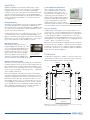
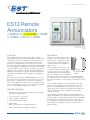
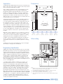
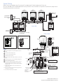
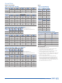
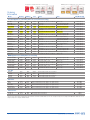
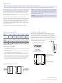
1
Architecture - Engineering - Planning www.mkcinc.com Mansfield, Ohio New Philadelphia, Ohio Powell, Ohio 419-525-1102 - phone 419-525-1428 - fax 330-364-8871 - phone 330-343-3075 - fax 740-657-3202 - phone 740-657-1717 - fax SHOP DRAWING REVIEW PROJECT NAME: Westlake High School JOB NO: SUBMITTAL ITEM: Fire alarm equipment 09-ED1-045A SPEC. REFERENCE: 28 31 12 MANUFACTURER: Edwards/GE REVIEWED REVIEWED AS NOTED REVISE AND RESUBMIT NOT ACCEPTED Checking is only for conformance with the design concept of the project and compliance with the information given in the contract documents. The Contractor is responsible for dimensions to be confirmed and correlated at the job site. For information that pertains solely to the fabrication processes or to techniques of construction and for coordination of the work of all trades. DATE: 12-04-2012 BY: TMM COMMENTS: THE FOLLOWING COMMENTS HAVE NOT BEEN MARKED ON THE ATTACHED SHOP DRAWINGS: 1. 2. 3. 4. Candela ratings of strobes are the responsibility of the fire alarm designer. All devices shall be individually addressed. All applicable comments as noted on shop drawing #283112-2-R-1 shall also apply. All horn/strobes and strobes of all types shall be “RED” in color. No white devices will be accepted. Shop drawing 283112-1 (revised) Kyle Richardson 283112-1 3/19/12 Material List Westlake High School Fire Alarm System ITEM NO DESCRIPTION EDW-3XSFS1B Edwards FACP with CPU, 1 Loop, 4 NACs, Power Supply- 3X-SFS1B EDW-3MODCOM Edwards EST3 Dialer 3-MODCOM EDW-3XNET Edwards Network Option Card, RS485, CI A or B, Max 64 Nodes EDW-BC1 GE Security Battery Cabinet - BC-1 EDW-3LCDANN GE Security LCD Annunciator with CPU and Door - 3-LCDANN EDW-RLCMB GE Security Flush Box for 3-LCDANN - RLCM/B EDW-BPS10A6 EDW-BPS10A Edwards 6 pack, Remote Booster Power Supply, 10amp, 120vac – BPS10A6 Edwards 10Amp Power Supply Booster - BPS10A EDW-SIGACC1S Edwards Riser Module w/sync SIGA-CC1S EDW-SIGA2PS Edwards Photoelectric Smoke Detector - SIGA2-PS EDW-SIGA2HFS Edwards Fixed Temp Heat Detector - SIGA2-HFS EDW-SIGASB4 GE Security Smoke Detector Base - SIGA-SB4 EDW-SIGASD GE Security Superduct SIGA-SD EDW-SDTRK GE Security Superduct Keyed Test station SD-TRK EDW-SDT60 Edwards Sample Tube SD-T60 EDW-SIGA278 GE Security Manual Pull Station SIGA-278 EDW-SIGACT1 Edwards Addressable Single Zone Module SIGA-CT1 EDW-SIGACR Edwards Addressable Relay Module SIGA-CR EDW-G1FHDVM Edwards Horn Strobe, White, with FIRE Marking - G1F-HDVM EDW-7578ATW Edwards 110cd Temporal Horn/Strobe - 757-8A-TW Phone: (330) 337-9916 [email protected] Fax: (330) 337-3461 Material List Westlake High School Fire Alarm System ITEM NO DESCRIPTION EDW-757AWBW Edwards Weatherproof Box, Cast - 757A-WBW EDW-G1FVM Edwards Strobe, White, with FIRE Marking - G1F-VM EDW-CS4058AT GE Security 110 Candela Outdoor Strobe Only - CS-405-8A-T EDW-449 GE Security Backbox Weatherproof - 449 EDW-1504AQN5 BAT-12V12AH Edwards Door Holder, Flush, Wall Mount, 24vac/dc or 120vac – 1504AQN% Battery, 12 Volt, 12AH - 12V12AH BAT-12V7AH Battery, 12V, 7AH - 12V7AH CHA-CSGWV642 Chase Wire Guard, 6" x 4" x 2" - CSGWV642 (G1R series) Phone: (330) 337-9916 [email protected] Fax: (330) 337-3461 EST Catalog u Mid-Sized Systems EST3X Life Safety Control System FDNY APPROVAL #6087 Description Standard Features EST3X represents the latest generation of life safety control panels for mid to large sized applications. With large multi-message displays and innovative controls, intuitive interfaces, and bold colored cabinets — these systems capture the imagination, and catch the eye. But behind the LCD display is where they really shine. • Up to six intelligent analog loops hosting as many as 1,500 Signature Series devices per panel New microprocessors and chipsets take full advantage of the latest advances in computing technology, leading to smarter, faster, higher-capacity processing and more efficient designs. EST3X’s patented Voltage Boost™ technology, for example, delivers consistent voltage – even at low battery power – resulting in lighter cable requirements and/or longer runs. That saves time and money. High performance processing also leads to powerful networking features and versatile digital audio functionality. The wide range of EST3X configurations include standalone operation, networking with up to 64 nodes, or integration with an EST3 network comprising as many as 64 nodes — complete with EST3-Sixty mass notification capabilities and display of security events. EST3X sets a new standard in front-panel life safety control interfaces. Its exclusive SpeedTouch™ rotary control offers nimble forward and back scrolling through events and options, while a mere tap of the control selects items with an unprecedented fluidity of motion. Its extra-large backlit display reveals up to eight concurrent messages, and switch/LED strips provide ample space for meaningful custom labels. And for end users, large tactile control buttons instill confidence and promote quick response when time is of the essence. Page 1 of 10 • Optional integrated eight-channel digital audio • 10 amp power supply with universal 94 to 264 Vac input voltage • Patented Voltage Boost™ technology delivers consistent voltage — even at low battery power • Four built-in 3-amp notification/auxiliary circuits • Large 24-line by 40-character backlit LCD • Simplified operation with the SpeedTouch™ rotary control • 65 amp hour battery charger • 64-node network nodes using copper and/or fiber • Supports up to 30 R-Series remote annunciators • Removable terminals on all low voltage wiring • Space for up to three additional option cards such as extra SLC loops, amplifiers, or dialer/modem • Optional Ethernet interface • 1,100 event history log 85005-0133 D ATA S H E E T Not to be used for installation purposes. Issue 3 Application Application flexibility is where EST3X’s leading edge computing power is put to best use. This generation of control panels is equally at home as the center of a simple single-building standalone system as it is when part of a sophisticated life safety network serving thousands of points across multiple buildings. Optional voice evacuation bridges the gap left by other mid-range systems, and makes these panels a cost-effective solution for most applications. Strong Networking Networking is among EST3X’s strong suits. Highly efficient RS485 connectivity, plus fiber-optic communications deliver faster response times and more sophisticated diagnostic capabilities, while cost-effective remote annunciation solutions keep basic monitoring and control always within reach. A simple EST3X network can comprise up to 64 nodes – enough to serve the needs of most campuses and larger buildings. Its ability to join an EST3 network with as many as 64 nodes extends EST3X’s reach into mass notification applications, security reporting, as well as making it an ideal candidate for retrofits. High Capacity Audio EST3X features a full eight channels of integrated digital audio with up to two minutes of on-board programmable message storage. An optional high quality paging microphone gives live access to local, as An optional paging microphone well as remote, audio functions. Auxiliary provides local, as well as remote, audio functions. inputs are available for mass notification operations, and ZA Series amplifiers may be mounted directly on the EST3X rail assembly. Seamless System Integration EST3X borrows much from it’s larger sibling, the venerable EST3 Life Safety Platform. And for good reason: by integrating with the EST3 networking and computing environment, an EST3X control panel can serve as a cost-effective remote node for extinguishing, smoke control, or even mass notification functions — all within the same compliance framework. Retrofits and expansions benefit enormously from this arrangement, but programming and equipment management for new installations is equally efficient as a result of these shared resources. EST3X will accommodate up to three EST3 modules on its own rail assembly, giving it access to such proven EST3 successes as zoned amplifiers, conventional device circuits, modem communicators, and RS-485 functions. Meanwhile, installers familiar with EST3 configuration will find that the two systems share many of the same programming and diagnostic conventions. Local and Remote Annunciation Up to 30 R-Series LCD, LED annunciators and driver interface cards may be configured for each node on the EST3X network. No additional nodes are required for annunciation purposes. In addition, EST3X supports EST3 network annunciators, while GCI and GCIX driver Up to 30 R-Series annunciators may be configured for each interface cards provide cost-effective node on the EST3X network. graphic annunciation solutions. And all annunciator inputs and outputs are easily programmable through the rules and labels function of EST3X’s Software Definition Utility. Power to Count On Edwards’ patented Voltage Boost™ technology delivers a consistent 22.5 Vdc – even at low battery power. This means lighter gauge cable can be used for equivalent distances compared with conventional power supplies, or longer wire runs on the same gauge cable. Either way, this breakthrough technology saves time and equipment costs, making EST3X not only a high-performance solution — but a cost-effective one as well. EST3X’s four on-board Notification Appliance Circuits are fully synchronized to UL 1971 standards — without the need for external modules or other electronics. It’s ample 10-amp power supply is finely tuned to get the most out of Edwards’ widely-acclaimed low profile Genesis notification appliances. Dimensions The backbox is designed for semiflush or surface mounting. Conduit and nail knockouts, keyhole style mounting holes, and wide wiring troughs facilitate efficiency during installation. LQFP 7RSYLHZ %DFNER[ 6LGHYLHZ 6LGHYLHZ %RWWRPYLHZ Note: Add 0.25 in (0.64 cm). to height and width dimensions to allow for knockouts when framing in the backbox for semiflush mounting. Page 2 of 10 85005-0133 D ATA S H E E T Not to be used for installation purposes. Issue 3 System Layout Wiring Up to six intelligent analog loops hosting as many as 250 devices each. SLC1 SLC2 Standard 3-SDC1 SLC3 SLC4 SLC5 3-SDDC1 (occupies one LRM expansion slot) Signature (initiating) Data Circuit SLC6 Required for Class A only 3-SDDC1 (occupies one LRM expansion slot) To two-wire smoke detector Auxiliary power, +24 V Auxiliary power, common Four 3-amp Class B NACs. Four Class A NACs with CLA-PS10. BB NAC 1 NAC 2 NAC 3 LOOP1 NAC 4 S H A S P BB 24+ C WM KR LOOP1L 1 OOP1 AUX A If shielding is used, it must be continuous and free from earth ground. All wiring is power limited. SFS1-CPU Main Board Notification Appliance Circuits PS10-4B Power supply Up to three EST3 Local Rail Modules including: •Signature Series Drivers •Zoned Amplifiers •Modem Communicators •Network Short Haul Modems •Fiber Optic Communications Interfaces •Hardwired Initiating Device Modules + Normal Active + + + + + + EOL resistor + Wiring is supervised and power limited. Up to three Control/Display Modules TB2 terminal marking indicates signal polarity when the circuit is not active. Polarity reverses when the circuit is active. For proper circuit supervision, break the wire run at each notification appliance and install the EOL resistor at the end of the circuit. Do not loop wires around notification appliance terminals. Ethernet (3X-ETH) Network data circuit A NETWORK OUT IN A BB R X 1 RS-232 Aux. Power: 24 VDC, 1.0 A total C O M 1 A RS-485 BUS B RS-485 BUS To next network node Class A only Network data circuit, Class B audio A 3X-NET, 3X-FIB R T S 1 SFS1-CPU Main Board Relays: 3 Form C Up to 30 Class B Annunciators. 4,000 ft. max. T X 1 NETWORK OUT IN A BB 3X-NET8, 3X-FIB8 R X 1 T X 1 R T S 1 C O M 1 A RS-485 BUS B RS-485 BUS SFS1-CPU Main Board To next network node 3-ASU/3X-PMI Primary Audio Data Or... Network data circuit, Class A audio A NETWORK OUT IN A BB R X 1 T X 1 R T S 1 C O M 1 A RS-485 BUS B RS-485 BUS SFS1-CPU Main Board UL Listed Signaling UL Listed Security Page 3 of 10 UL Listed Life Safety Detection UL Listed Mass Notification 3-ASU/3X-PMI Primary Audio Data UL Listed Signaling To next network node UL Listed Life Safety Detection 85005-0133 D ATA S H E E T Not to be used for installation purposes. Issue 3 Main Component Assembly SFS1-CPU Main Board EST3X systems are designed for quick assembly and easy access in the field. Components are modular and require no special tools to service or replace. The SFS1-CPU main board processes all information from modules installed within the cabinet as well as data received from other panels over the network data riser. When a network card is installed, the CPU employs a command set to determine its type. The 3-SFS1 Electronics Chassis provides the mounting, internal power, and data distribution for the SFS1-CPU main board and up to three local rail modules. It installs over the PS10-4B Power Supply. SFS1-CPU Specifications Voltage Current 24 VDC Standby Alarm 115 mA at 24 VDC 115 mA at 24 VDC Relay outputs The SFS1-CPU main board mounts to the Electronics Chassis. Chassis Assembly Common Relay Outputs SLC1 Signaling line circuit Network, annunciator, RS-232 circuits SFS1-CPU Main Board SLC2 Signaling line circuit Two cables connect the PS10-4B Power Supply to the back of the SFS1CPU main board. PS10-4B Power supply SFS1-CPU Main Board The 4X-LCD assembly mounts to hinge pins on the CPU and connects with a single ribbon cable. Notes • For battery calculations, standby and alarm currents include all listed primary power supplies. • The common trouble relay operation does not include AC trouble delay functionality and cannot be used for reporting troubles off premises per UL 864 9th edition. 4X-LCD User Interface Page 4 of 10 Quantity 3 (alarm, supervisory, and trouble) UL type Common Contact arrangement Form C Rating 30 VDC at 1 A AUX power outputs Quantity 2 Voltage 24 VDC, resettable or continuous Current 1.0 A each circuit, 1.0 A total Data network (RS-485) Nodes 2 to 64 (requires optional network card) Performance class Class A or Class B Wire type Twisted pair, 6 twists per foot, min. Circuit length 5,000 ft. (1,524 m) between any three panels Circuit resistance 90 Ω, max. Circuit capacitance 0.3 μF, max. Serial Port (RS-232) Circuit length 20 ft. (6 m) max. Circuit resistance 13 Ω, max. Circuit capacitance 0.7 μF, max. Annunciator port (RS-485) Performance class Class B and Redundant Class B Baud rate 9600 and 38400 Wire type Twisted pair, 6 twists per foot, min. Circuit length 4,000 ft. (1,219 m) Circuit resistance 90 Ω, max. Circuit capacitance 0.3 μF, max. Signaling line circuit Quantity 2 (second SLC requires optional 3-SDC1 card) Performance class Class A or Class B Circuit capacity 125 detectors, 125 single address modules Circuit resistance 100 Ω, max. Circuit capacitance 0.5 μF, max. Wire size 18 to 12 AWG (0.75 mm² to 2.50 mm²) Ground fault 10 kΩ impedance Operating environment Temperature 32 to 120°F (0 to 49°C) Relative humidity 0 to 93% noncondensing SFS1-CPU Main Board 85005-0133 D ATA S H E E T Not to be used for installation purposes. Issue 3 PS10-4B Power Supply Card 3-SDC1 Signature Data Circuit Card The PS10-4B Power Supply Card provides the required power and related supervision functions for the control panel, as well as filtered, regulated power to the rail chassis modules. It also provides 24 VDC for operating ancillary equipment. Each 3-SDC1 Signature Data Optional Circuit Card provides one Class SDC1 card for SLC2 A or Class B signaling line circuit (SLC1) that supports up to 125 Signature Series detectors and SFS1-CPU 125 Signature Series module Main Board addresses. These modules also provide connection for powering conventional two-wire smoke detector circuits on Signature Series modules. PS10-4B Specifications Mains voltage AC Input Current 94 to 264 VAC, 50/60 Hz Standby 1.5 amps Alarm 3.0 amps Brownout level 93 VRMS Battery charging capacity 65 Ah max. Total Power Voltage 24vdc Supply Ratings Current 10 amps (UL), 9.0amps (ULC) Notification appliance/Auxiliary power circuits UL rating Quantity 4 Circuit configuration Class B1 Output voltage Special: 24 Vdc Regulated: 24 Vdc Output current Special: 3 amps Regulated: 1.5 amps EOLR 15 kΩ (UL P/N EOL-15, ULC P/N EOL-P1) Wiring Mains input 2 Supervised, non power-limited Battery input Supervised, non power-limited NAC outputs Supervised, power-limited Wire size 18 to 12 AWG (0.75 mm² to 2.50 mm²) Ground fault impedance 10 kΩ Operating environment Temperature 32 to 120 °F (0 to 49 °C) Relative humidity 0 to 93% noncondensing Standard SDC1 card for SLC1 EST3X comes standard with one 3-SDC1 card installed as SLC1. An optional second 3-SDC1 card may be installed to provide SLC2, thus doubling system signaling line capacity. 3-SDC1 Specifications Voltage Operating Current Standby Alarm Smoke power Circuit Configuration Capacity 24 VDC 3-SSDC1 144 mA; 3-SDDC1 264 mA 3-SSDC1 204 mA; 3-SDDC1 336 mA 19.95 VDC max.1 Class B, Style 4, DCLB; Class A, Style 6, DCLA 125 Signature Series detectors and 125 Signature Series modules per SLC Resistance 100 Ω with 250 devices Capacitance 0.5 μF max. Wire size 12 AWG (1.5 mm²) max. Termination Removable plug-in terminal strips on the SFS1-CPU main board and Signature module Operating environment Temperature 32 to 120 °F (0 to 49 °C) Relative humidity 0 to 93% noncondensing 1 For special applications, refer to EST3 ULI/ULC Compatibility Lists (P/N 3100427) Class A when a CLA-PS10 Class A adapter card is installed. 2 Connect the mains supply using a dedicated branch. 1 4X-LCD User Interface SFS1 LED Control/ Display Module Included in the EST3X basic package, the 4XLCD provides the user interface for the EST3X system. It connects to the SFS1-CPU main board with a ribbon cable, and attaches to the CPU via hinges. Only one display module is required to provide a point of control for the entire network. Additional displays can be added to any EST3X panel in the network to provide additional points of control. The SFS1 LED Control/Display Module provides additional operator interface capability for the SFS1 system. It can be mounted on any of the three rightmost local rail modules on the 3-SFS1 electronics chassis. Inserts are provided for labeling switches and LEDs. 4X-LCD Specifications Operating current Standby Alarm LCD display Operating environment Temperature Relative humidity Page 5 of 10 38 mA 50 mA Backlit liquid crystal display 240 x 320 pixels 24 lines of 40 characters SFS1 LED Control/ Display Module Rail Module SFS1 Specifications Voltage Operating current Standby Alarm Operating environment Temperature Relative humidity 24 VDC 2.0 mA plus 1.5 mA for each active LED 2.0 mA plus 1.5 mA for each active LED 32 to 120 °F (0 to 49 °C) 0 to 93% noncondensing 32 to 120 °F (0 to 49 °C) 0 to 93% noncondensing 85005-0133 D ATA S H E E T Not to be used for installation purposes. Issue 3 3X-FIB fiber optic network module SFS1-CPU Main Board The 3X-FIB fiber optic network module gives an EST3X panel the ability to network 64 or more EST3X panels, or interface with an EST3 network. Both Class A and Class B connections are supported. The module consists of the adapter card and electronics card. 3X-FIB8 adapter card The 3X-FIB supports the following fiber optic transceivers: Model SMXLO2 SMXHI2 MMXVR Description Standard output single mode fiber optic transceiver High output single mode fiber optic transceiver Standard output multimode fiber optic transceiver 3X-FIB8 fiber optic network module SFS1-CPU Main Board The 3X-FIB8 fiber optic network module gives an EST3X panel the ability to network up to eight other EST3X nodes. Both Class A and Class B connections are supported. The module consists of the adapter card and electronics card. 3X-FIB adapter card The 3-FIB8 supports the following fiber optic transceivers: Model SMXLO2 SMXHI2 MMXVR Description Standard output single mode fiber optic transceiver High output single mode fiber optic transceiver Standard output multimode fiber optic transceiver The 3X-FIB provides terminals for connecting a 24 VDC backup power source to maintain data transmissions in the event the panel is powered down. The 3X-FIB8 provides terminals for connecting a 24 VDC backup power source to maintain data transmissions in the event the panel is powered down. Note: All networked panels must have the 3X-FIB network card installed. Note: All networked panels must have the 3X-FIB8 network card installed. 3X-FIB Specifications 3X-FIB8 Specifications Voltage 19.2 to 27.6 VDC (24 VDC nominal) Fiber optics network and audio Budget SMXLO2 15 dBm between two interfaces SMXHI2 25 dBm max. and 8 dBm min. 10 dBm between two interfaces MMXVR 50/125, 62.5/125, or 100/140 for MMXVR Cable type Connectors 50/125, 62.5/125, or 100/140 for SMXLO2, SMXHI2 Type Duplex SC MMXVR Type ST Network data circuit Circuit configuration Class B (style 4) or Class A (style 7) Data rate 19.2 K, 38.4 kbps Isolation Isolated from previous panel CPU when using copper. Total isolation when using fiber optics. Digitized audio data circuit Circuit configuration Class B (style 4) or Class A (style 7) Data rate 327 kbps Isolation Isolated from previous panel CPU when using copper. Total isolation when using fiber optics. Copper wired network data circuit segment Circuit Length 5,000 ft. (1,524 m) max. between any three panels Resistance 90 Ω max. Capacitance 0.3 µF max.1 Wire type Twisted Pair, 18 AWG (0.75 mm²) min. Operating environment Temperature 32 to 120 °F (0 to 49 °C) Relative humidity 0 to 93% noncondensing Include shield capacitance, if shielding is used. 1 Page 6 of 10 Voltage 19.2 to 27.6 VDC (24 VDC nominal) Fiber optics network and audio Budget SMXLO2 15 dBm between two interfaces SMXHI2 25 dBm max. and 8 dBm min. 10 dBm between two interfaces MMXVR 50/125, 62.5/125, or 100/140 for MMXVR Cable type Connectors 50/125, 62.5/125, or 100/140 for SMXLO2, SMXHI2 Type Duplex SC MMXVR Type ST Network data circuit Circuit configuration Class B (style 4) or Class A (style 7) Data rate 19.2 K, 38.4 kbps Isolation Isolated from previous panel CPU when using copper. Total isolation when using fiber optics. Digitized audio data circuit Circuit configuration Class B (style 4) or Class A (style 7) Data rate 327 kbps Isolation Isolated from previous panel CPU when using copper. Total isolation when using fiber optics. Copper wired network data circuit segment Circuit Length 5,000 ft. (1,524 m) max. between any three panels Resistance 90 Ω max. Capacitance 0.3 µF max.1 Wire type Twisted Pair, 18 AWG (0.75 mm²) min. Operating environment Temperature 32 to 120 °F (0 to 49 °C) Relative humidity 0 to 93% noncondensing Include shield capacitance, if shielding is used. 1 85005-0133 D ATA S H E E T Not to be used for installation purposes. Issue 3 3X-NET Network Adapter Card The 3X-NET network adapter card gives an SFS1-CPU main board the ability to network up to 64 nodes on an EST3 network. The card supports Class B and Class A wiring. SFS1-CPU Main Board 3X-NET card The 3X-NET adapter card provides two independent RS 485 circuits: one for network data communications and one for digital audio communications. 3X-NET Specifications Voltage 24 VDC Operating Current Standby 98 mA at 24 VDC Alarm 98 mA at 24 VDC Circuit configuration Network data Class A, Style 6 & Class B, Style 4 Network audio Class A, Style 6 & Class B, Style 4 Isolation Network data Network A port not isolated; Network B port isolated Network audio Audio A IN and Audio B IN isolated Audio A OUT and Audio B OUT not isolated Wire size Twisted pair1 18 AWG (0.75 mm) min. Circuit length 5,000 ft. (1,524 m) between any three panels Circuit resistance 90 Ω max. Circuit capacitance Data: 0.3 μF max.; Audio 0.09 μF max. Operating environment Temperature 32 to 120 °F (0 to 49 °C) Relative humidity 0 to 93% noncondensing Six twists per foot minimum 1 3X-NET8 network card SFS1-CPU Main Board The 3X-NET8 RS-485 network card gives an SFS1-CPU main board the ability to network through dedicated copper wire up to 64 EST3X control panels. The card supports Class B and Class A wiring. 3X-ETH1 Ethernet Adapter Card The 3X-ETH1 adapter card provides a standard 10/100 Base-T Ethernet network connection for panel programming, diagnostics, and status monitoring. Four LEDs on the adapter card indicate card and network status. SFS1-CPU Main Board 3X-ETH card 3X-ETH1 Specifications Ethernet Voltage Operating current Standby 10/100 Base-T 24 VDC 44 mA at 24 VDC (54 mA when connected to an active Ethernet connection) Alarm 44 mA at 24 VDC Connection mode Auto negotiation Copper wired network data circuit segment Circuit Length 5,000 ft. (1,524 m) max. between any three panels Resistance 90 Ω max. Capacitance 0.3 µF max.1 Wire type Twisted Pair, 18 AWG (0.75 mm²) min. Copper wired audio data circuit Circuit Length 5,000 ft. (1,524 m) max. between any 3 panels Resistance 90 Ω max. Capacitance 0.09 µF, max1 Wire type Twisted pair, 18 AWG (0.75 sq²) min. Wire runs Distance 200 ft. (60 m) max.1 Type Cat 5 Connector RJ-45 Operating environment Temperature 32 to 120 °F (0 to 49 °C) Relative humidity 0 to 93% noncondensing 1 Panel to communication equipment 3X-NET8 card Note: All networked panels must have a 3X-NET8 network card installed. 3X-NET8 Specifications Voltage 24 VDC Operating Current Standby 98 mA at 24 VDC Alarm 98 mA at 24 VDC Circuit configuration Network data Class A, Style 6 & Class B, Style 4 Isolation Network data Network A port not isolated, Network B port isolated Wire size Twisted pair1 18 AWG (0.75 mm) min. Circuit length 5,000 ft. (1,524 m) between any three panels Circuit resistance 90 Ω max. Circuit 0.3 μF max. capacitance Operating environment 32 to 120 °F (0 to 49 °C) Temperature 0 to 93% noncondensing Relative humidity 1 Six twists per foot min. Page 7 of 10 85005-0133 D ATA S H E E T Not to be used for installation purposes. Issue 3 3X-PMI Paging Microphone Interface CLA-PS10 Class A Adapter Card The 3X-PMI Paging Microphone Interface provides controls for emergency voice/alarm communications. It consists of an audio mounting bracket, EAEC Emergency Audio Evacuation Controller card, audio enclosure, and paging microphone. The CLA-PS10 Class A Adapter Card is an optional card used to convert the four Class B notification appliance/auxiliary power circuits on the power supply card to Class A. CLA-PS10 Specifications 3X-PMI Paging Microphone Interface Specifications Voltage Current 24 VDC Standby 15.5 mA Alarm 16.6 mA Ground fault impedance 10 kΩ Wire size 18 to 12 AWG (0.75 to 2.50 mm²) Audio channels 8 simultaneous Audio inputs Local microphone Isolated and supervised Remote microphone Isolated and supervised Remote audio Isolated and supervised EAEC communication See the EAEC Emergency Audio Evacuation Control Installation Sheet (P/N 3101789) Messages Storage 2 min. total Length 39 sec. max. Controls and indicators Common Paging Volume Indicates relative signal strength during active page Ready To Page Flashes during preannouncement Paging Microphone tone, steady when ready to page All Call Activates/deactivates page to all areas All Call Minus Activates/deactivates page to areas not receiving EVAC or Alert message Page To Evac Activates/deactivates page to areas currently receiving the EVAC message Page To Alert Activates/deactivates page to areas currently receiving the Alert message Operating environment Temperature 32 to 120°F (0 to 49°C) Relative humidity 0 to 93% noncondensing PS10-4B Power supply CLA-PS10 Class A Adapter Card Voltage 24 VDC Notification appliance/Auxiliary power circuits UL rating Special application or Regulated Quantity 4 Performance class Class A Output current Special 3.0 A; Regulated: 1.5 A each circuit EOLR 15 kΩ (UL P/N EOL-15, ULC P/N EOL-P1) Wiring Supervised, power-limited Wire size 18 to 12 AWG (0.75 mm² to 2.50 mm²) Operating environment Temperature 32 to 120 °F (0 to 49 °C) Relative humidity 0 to 93% noncondensing SFS1-CPU NETWORKA OUT IN AA BB ++- UDIO A IN +- AUDIOA A OUT +- Network option card installed UDIO B IN +- AUDIO B OUT +- R X 1 T X 1 R T S 1 C O M 1 AB RS-485 BUSB -+ + RS-485 US - Network option card not installed KEY_OUT AUDIO_OUT Remote microphone SHIELD MN-PASM MN-FVPN EAEC AUDIO DATA Page 8 of 10 KEYA UDIO UL 864 and UL 2572 listed equipment with compatible ratings AUX OUTA UX IN REMOTE MIC 85005-0133 D ATA S H E E T Not to be used for installation purposes. Issue 3 Ordering Information Intelligent Analog Control Panels Model 3X-SFS1B 3X-SFS1R 3X-SFS1Bi 3X-SFS1Ri TRIM6 Door Color Bronze Red Bronze Red Language English Description FACP, complete system with user interface, CPU, one loop with second loop expansion, three option card slots, four Class B NAC, universal 110/220v 10 amp power supply. Order 3-SDC1 for second loop. Selectable Flush trim ring Network communication option cards 3X-NET8 RS485, eight node max. Class A/B network. Use on 3-SFS systems only. 3X-NET RS485, Class A/B network. For connection to EST3 systems. 3X-FIB8 Fiber, 8 node max. Uses MMXVR, SMXHI2, SMXLO2. Use on 3-SFS systems only. 3X-FIB Fiber motherboard for connection to EST3 systems. Used with MMXVR, SMXHI2 and SMXLO2. SMXLO2 Standard output single mode fiber optic transceiver SMXHI2 High output single mode fiber optic transceiver MMXVR Standard output multimode fiber optic transceiver Communication Options 3X-ETH1 Ethernet Adapter, 10/100. Provides Ethernet connection from system to 3-SDU for remote programming and diagnostics. Uses standard Ethernet cable (not supplied). Front Panel LED/Switch display modules 4X-12/S1GY LED Display/Control Module - 12 Switches, 1 Green, 1 YELLOW LED per switch. 4X-12/S1RY LED Display/Control Module - 12 Switches, 1 RED, 1 YELLOW LED per switch. 4X-12SR LED Display/Control Module - 12 Switches with 12 RED LEDs. 4X-12RY LED Display Module - 12 pairs of LEDs (1 Red; 1 Yellow) 4X-24Y LED Display Module - 24 YELLOW 4X-24R LED Display Module - 24 RED 4X-6/3S1G2Y LED/Switch Module - six groups of three Switches with one LED each. 4X-6/3S1GYR LED/Switch Module - six groups of three Switches with one LED each. 4X-4/3SGYWR LED/Switch Module, four groups of three switches and four LEDs. LED colors: Green, Red, Yellow and White. 4X-LKF Label Kit, French Option Cards and Interfaces 3X-PMI Paging Microphone Interface 3-SSDC1 Single Signature Driver Controller, c/w one 3-SDC1 3-SDDC1 Dual Signature Driver Controller, c/w two 3-SDC1s 3-SDC1 Signature Device Card - expands the 3X base panel to two loops 3-ZA20A 20 Watt Zoned Amplifier w/Class A/B Audio & Class A/B 24 VDC outputs 3-ZA20B 20 Watt Zoned Amplifier w/Class B Audio & Class B 24 VDC outputs 3-ZA40A 40 Watt Zoned Amplifier w/Class A/B Audio & Class A/B 24 VDC outputs 3-ZA40B 40 Watt Zoned Amplifier w/Class B Audio & Class B 24 VDC outputs 3-MODCOM Modem/Dialer (DACT) 3-MODCOMP Modem/Dialer (DACT) w/TAP Pager Protocol 3-AADC1 Addressable Analog Module 3-IDC8/4 Initiating Device Circuit Module 3-OPS Off Premises Signaling module CLA-PS10 Class A Adapter, PS10 NACs CDR-3 PSNI Coder Module GCI Graphic Annunciator Driver Master, provides outputs for 32 LEDs and connection to common control switches and LEDs for R-Series annunciators. GCIX Graphic Annunciator Driver Expander, provides outputs for 48 LEDs and inputs for 24 switches. Page 9 of 10 85005-0133 D ATA S H E E T Not to be used for installation purposes. Issue 3 Detection & alarm since 1872 U.S. T 888 378 2329 F 866 503 3996 Canada Chubb Edwards T 519 376 2430 F 519 376 7258 Southeast Asia T : +65 6391 9300 F : +65 6391 9306 India T : +91 80 4344 2000 F : +91 80 4344 2050 Australia T +61 3 9239 1200 F +61 3 9239 1299 Accessories PS10-4B Power Supply, Replacement SFS1-ELEC Base Electronics, replacement 4X-LCD Main user interface assembly, monochrome. Eight line 1/4 VGA LCD, four controls plus rotary knob. English language. 4X-LCD-LC Main user interface assembly, monochrome. Eight Line 1/4 VGA LCD, four controls plus Rotary knob. Insertable language, shipped with English inserts. Order alternate languages separately. 4X-CAB6D Replacement door, bronze 4X-CAB6DR Replacement door, red 4X-CAB6B Backbox, black Related Data Sheets 85010-0129 -- Signature Driver Controller Modules 85010-0057 -- EST3 Zoned Audio Amplifiers 85010-0107 -- EST3 Modem Communicator 85010-0131 -- Fiber Optic Communications Interface 85010-0113 -- Network Short Haul Modem 85005-0128 -- R-Series Remote Annunciators Europe T +32 2 725 11 20 F +32 2 721 86 13 Latin America T 305 593 4301 F 305 593 4300 utcfireandsecurity.com © 2011 UTC Fire & Security. All rights reserved. 85005-0133 D ATA S H E E T Not to be used for installation purposes. Issue 3 02-13-12 Page 10 of 10 EST Catalog u EST3 Life Safety Platform Hinged Bracket Filler plate (ordered separately) Module Modem Communicator 3-MODCOM, 3-MODCOMP Overview Standard Features The Modem Communicator is a two-way local rail module that performs a variety of off-premise communications functions for the EST3 system. • Listed for fire, security and access control Using the latest in digital signal processing (DSP) techniques, the Modcom provides off premise communication features unavailable on any other system. The module has provisions for supervising two loop-start telephone lines. The module features a modular jack for telephone line connections. The Modcom’s configuration and firmware can also be updated from any network node. Modcom series modules occupy a single local rail space and can be mounted in any node on the network. Any EST3 Control/ Display module can be mounted on the face of a Modcom series module. Power for the Modcom is supplied by the EST3 system supply. The Modcom provides an enhanced level of survivability in the event of a network CPU failure by notifying the Central Monitoring Station of the failure and entering a degraded mode of operation. In degraded mode, the Modcom can transmit a default fire alarm message during a fire alarm condition. Page 1 of 4 • V.32bis 14.4K full duplex modem • Digital alarm communicator transmitter supporting: SIA DCS protocol, Contact ID protocol, 3/1 and 4/2 pulse format protocol • Supports “tap” alphanumeric pager protocol • Fully programmable messages • Alarm override of upload/download • Two phone line capability • Field upgradable firmware • Split and multiple reporting to as many as 80 different receivers • 255 subscriber accounts • Supports control/display modules • Supervised by the network controller 85010-0107 D ATA S H E E T Not to be used for installation purposes. Issue 5.1 Application Two versions of the Modcom are available: 3-MODCOM - Has an internal V.32bis 14.4K baud full duplex modem. The modem permits upload and download of system data remotely via a telephone line. In addition, the 3-MODCOM has a Digital Alarm Communications Transmitter (DACT) or dialer function that transmits network status information to Central Monitoring Stations (CMS) via telephone. Four DACT protocols are available: 1. Digital Communicator Standard (DCS) “SIA forma” Dialer – 300 baud format, which transmits alphanumeric system status data to the CMS; 2. Contact ID; 3. SIA 3/1 dialer; and, 4. SIA 4/2 dialer. Alarm code content is determined by system rules. 3-MODCOMP – In addition to all modem and dialer (DACT) functions of the 3-MODCOM, the 3-MODCOMP can dial directly into paging systems using Telelocator Alphanumeric Protocol (TAP). Alphanumeric system data can be sent to a single pager or group(s) of pagers. Some pager services can forward messages via e-mail and Fax. Multiple Priority Each Modcom can buffer up to 500 events in its event queue. It reviews all active events in the queue and identifies the highest priority event and dials the associated receiver. When the receiver is contacted, the MODCOM will transmit the highest priority message for that receiver. If the message is successfully received, the MODCOM identifies the next highest priority message and the process repeats. Phone Line Friendly The Modcom series has been designed for installation on the same phone lines with other devices such as phones and faxes. The module makes its first dial out attempt on either of the two phone lines that is not in use. This prevents unnecessary interruption of calls in progress by the line seizure relays. In the event that both lines are busy, the module seizes line one. A fixed DACT testing time can be set at an off-hour, e.g. 2:00am, again minimizing interruptions and phone line costs. The call time is programmable, and allows testing of the DACT with the central station. The Modcom series also has the ability to detect Type 1, Type 2 and Type 3 distinctive ringing patterns, permitting it to share its phone lines with other devices and still have a unique phone number for incoming modem calls. Multiple Modcoms per Network Multiple Modcoms can be installed in a single cabinet or located in nodes throughout the network to provide added availability and enhanced redundancy of off premise communications. Multiple Receiver Capability In large system applications the EST3 system may be partitioned such that it supports a number of different customers, each using different Central Monitoring Stations and/or paging companies. The Modcom can accommodate up to 255 different accounts using up to 80 different receivers. multi-dial reporting capability permits an individual event to be transmitted to multiple receivers, including pagers. Remote Data Upload/Download The modem permits data to be downloaded into the memories of the various components making up an EST3 system. Data can be remotely uploaded and downloaded for use with the Edwards Access Control Database Program. In the event that an alarm is received during upload/download activity, the Modcom automatically terminates the call and transmits the alarm events to the appropriate receivers. When completed sending the events, the download will continue where it left off. Engineering Specification The system shall provided an off premise communications module capable of transmitting system events to multiple Central Monitoring Station (CMS) receivers. The module shall provide the CMS with point identification of system events via 4/2, Contact ID or SIA DCS protocols. <The module shall also be capable of transmitting alphanumeric system activity by event to a commercial paging system using TAP Pager protocol.> The dialer shall have the capability to support up to 255 individual accounts and to send account information to eighty (80) different receivers, each having a primary and secondary telephone access number. System events shall be capable of being directed to one or more receivers depending on event type or location as specified by the system designer. The module shall have a degrade mode capable of transmitting fire alarm signals to the CMS in the event of system CPU failure. The module shall provide a high speed (V.32bis or greater) modem function in order to upload and download system data to/from a remote location. Typical Wiring SURGE PROTECTOR RING (RED) GREEN RED 4 TIP (GREEN) 5 3 6 2 7 1 8 PREMISES PHONES TO PHONE LINE #2 (WIRED SAME AS PHONE LINE #1) RJ31X 8 PIN MODULAR CONNECTOR FOR PHONE LINE #1 4 5 3 6 7 2 1 RJ31X 8 PIN MODULAR CONNECTOR FOR PHONE LINE #2 8 1 NO T-TAPS PERMITTED 7 Ft. (2.13 M) LINE 1 LINE 2 MODCOM (front view) 2 Notes: 1 Connect Line 1 and Line 2 to RJ31X or RJ38X (CA31A or CA38A in Canada) telephone jacks installed by an authorized telephone company representative. Jacks (not supplied) must be installed within 5 ft. (1.5 m) of the panel. 2 Phone Cord (P/N 360137) supplied) is supervised and non-power limited. The Modcom supports split reporting, a process where the system directs the Modcom to send some events or event types to one receiver, and different events to alternate receivers. The module’s Page 2 of 4 85010-0107 D ATA S H E E T Not to be used for installation purposes. Issue 5.1 Specifications Agency Listings Installation Input Power Modem Protocol Dialer Protocol Pager Protocol (3-MODCOMP only) Telephone Dialing Connector CMS Telephone Numbers Quantity Available Digits Receivers Event Buffer Operating Environment Receivers Tested Format 4/2 and 3/1 Contact ID SIA DCS UL, FCC Part 68 / CFR 47, ULC. See Note 1. Takes up one LRM space in 3-CHAS7 24 Vdc @ 60mA standby, 95 mA active ITU - V.32bis 14.4K baud full duplex using standard PC modem compatible data SIA 3/1 (format P2) and 4/2 (format P3): 20 pulses per second, double round Contact ID (DTMF format) Digital Communications Standard (DCS) “SIA format”: Level 2 (300 baud, Bell 103) Telocator Alphanumeric Protocol (TAP), Version 1.8, 300 baud, Bell 103 Pulse or Tone (DTMF) Two 8-position modular phone jacks Two per receiver - 160 max. Up to 24 digits per number Supports up to 80 individual receivers. 500 events 32°F (0°C) to 120°F (49°C), 93% RH Non-condensing Manufacturer Ademco FBI (Fire Burglary Instruments) Osborne-Hoffman Radionics Silent Knight Sur-Gard MCDI Ademco Osborne-Hoffman Sur-Gard Radionics Silent Knight MCDI Sur-Gard Model 685 CP220 OH2000 D6600 9000 MLR2, SG-SLR TLR, TLR+ 685 OH2000 MLR2, SG-SLR D6600 9000 TLR, TLR+ MLR2, SG-SLR Receiver Card 685-1 or 685-8 9032 685-8 9032 Note 1: The EST3 is modularly listed under the following standards: UL 864 categories: UOJZ, UOXX, UUKL and SYZV, UL 294 category ALVY, UL 609 category AOTX, UL 636 category ANET, UL 1076 category APOU, UL 365 category APAW, UL 1610 category AMCX, UL 1635 category AMCX ULC-S527, ULC-S301, ULC-S302, ULC-S303, ULC-S306, ULC/ORD-C1076 and ULC/ORD-C693 Please refer to EST3 Installation and Service Manual for complete system requirements. Ordering Information Catalog Number 3-MODCOM 3-MODCOMP 3-FP Page 3 of 4 Description Modem/Dialer (DACT) version Modem/Dialer (DACT) w/TAP Pager Protocol Filler Plate, order separately when no LED or LED/Switch module installed. Ship Wt. lb (kg) 0.5 (0.23) 0.5 (0.23) 0.1 (0.05) 85010-0107 D ATA S H E E T Not to be used for installation purposes. Issue 5.1 Detection & alarm since 1872 U.S. T 888-378-2329 F 866-503-3996 Canada Chubb-Edwards T 519 376 2430 F 519 376 7258 Southeast Asia T : +65 6391 9300 F : +65 6391 9306 India T : +91 80 4344 2000 F : +91 80 4344 2050 Australia T +61 3 9239 1200 F +61 3 9239 1299 Europe T +32 2 725 11 20 F +32 2 721 86 13 Latin America T 305 593 4301 F 305 593 4300 utcfireandsecurity.com © 2010 UTC Fire & Security. All rights reserved. 85010-0107 D ATA S H E E T Not to be used for installation purposes. Issue 5.1 06-21-10 Page 4 of 4 EST Catalog u EST3 Life Safety Platform EST3 Remote Annunciators 3-ANNCPU3, 3-LCDANN, 3-6ANN, 3-10ANN, 3-EVxxx, 3-4ANN EN54-2:1997+A1 and EN54-4:1997+A1:2002+A2 pending Overview Application EST3 supports a full range of annunciator options for Mass Notification/Emergency Communication (MNEC), Life Safety and other purposes. Annunciator cabinets are constructed from 16 gauge cold rolled steel. The gray textured enamel finish of the annunciators complements any decor. Both surface and semiflush mounting cabinet configurations maximize mounting flexibility and esthetic appeal. Cabinet arrangements allow both LED and LCD annunciation to easily combine in a single enclosure. Slide in labeling for LEDs and switches provides designation flexibility for labeling in local languages. For graphic annunciation EST3 offers LED driver boards perfectly suited to operate in most graphic annunciators. Use EST3 remote annunciators when a compact system status display is needed. Annunciator configurations include: LCD only display, LED only displays or combination LED and LCD display in a single enclosure. EST3 annunciators are perfect for MNEC applications. They can be used in Central Control Stations (CCS), Autonomous Control Units (ACU), Local Operating Console (LOC) and combination units. In these applications, annunciators are configured to operate as Local Operation Consoles, or even Central Command Stations, from which MNEC is initiated and controlled. Standard Features • Standard 3-LCD (168 characters) and large-format 3-LCDXL1 (960 character) display options • LCD uses queues to sort events • Variety of wallbox configurations • Programmable LED flash rates • Slide-in labels Makes customization for regional language easy Display The LCD display uses either the 3-LCD Label or 3-LCDXL1 Liquid crystal display module. The 3-LCD has a 128 x 64 graphiAnnunciator Support cal display typically used to display eight Module lines of 21 characters on its LCD display while the 3-LCDXL1 has a larger 240 x 320 pixel backlit display that supports 24 lines of 40 characters. Both LDC displays provide the room needed to convey emergency information in a useful format. The 3-LCD always displays the last highest priority event even when the user is viewing other message queues. To give the greatest message flexibility EST3 event messages can route to specific annunciators. Routing can be initiated at a specific time/ shift change. Messages need only display in areas having to respond to an event. For LED display, the full line of EST3 Control/Display Modules support event display. Control/Display modules install over any annunciator support module maximizing annunciator design flexibility. A Lamptest feature can program to any spare control switch. If an LCD display is installed in the annunciator, simply operate the Alarm Silence and Trouble Silence switches simultaneously to lamptest all LEDs. • Full line of driver boards for graphic annunciators Page 1 of 4 85010-0069 D ATA S H E E T Not to be used for installation purposes. Issue 10 Typical Wiring Graphic Annunciator Field Wiring Rear view 3-ANNCPU3 Field Wiring 3-6ANN Shown 1 2 3 4 5 6 NETWORK A 7 8 To Backbox 24VDC FROM 3-PPS/M OR 3-BPS/M POWER RISER NETWORK B SPARE 24 VDC 24 VDC EARTH GROUND Ground Lead RS-485 NETWORK DATA FROM PREVIOUS PANEL 9 1 Power limited circuit 1 RS-485 NETWORK DATA TO NEXT PANEL 24VDC TO NEXT POWER MODULE 1 Graphic Annunciator 10 To TB1 on 3-ANNCPU3 TX RX TX RX TX RX TX RX RX TX RX TX RX TX RX TX NOTES: 1. All wiring except earth ground supervised and power limited. 2. 24 VDC available from Primary or Booster Power supply. 3. Uses RS-485 Network communication format 4. Network wiring Twisted Pair Wire Specifications Network Data Communications - RS485 Format Minimum Twisted Pair Maximum Circuit Resistance Maximum Circuit Capacitance Maximum Distance between any 3 panels Power Riser Calculate wire size for a maximum 3.4 Vdc total line loss from the 24 Vdc nominal voltage. 18 AWG (0.75 mm²). 90 Ohms 0.3 µF 5,000 ft. (1,524 m). Capacitance, entire network Maximum Accumulative Capacitance Wire Size 18 AWG 16 AWG 14 AWG 38.4K Baud 1.4 µF 1.8 µF 2.1 µF 19.2K Baud 2.8 µF 3.6 µF 4.2 µF Distance limits are determined using the maximum allowable circuit resistance and capacitance, and manufacturer’s cable specifications. Specifications Catalog Number Agency Listings 3-ANNCPU3 3-ANNSM 3-LCD UL, ULC, FM, CE, LPCB EN54* pending. Mounting Space Two Spaces One Space Mounts over 3-ANNCPU RS-485 N/A N/A Mounts over 3-ANNCPU plus two spaces. N/A 144 mA 144 mA Plug in terminal strip Twisted Pair 18-14 AWG (0.75-1.5 mm²) 5000 ft (1524m) between any 3 panels 10mA 10mA 40mA 42mA 48mA 50mA Communication Format Current @ 24 Vdc Standby Alarm Wiring Termination Wiring Size Max. Wire Distance Relative Humidity Temperature Rating Wiring Styles 3-LCDXL1 N/A 93% non condensing at 90° F (32° C) 0-49° C (32 - 120° F) Class A or Class B Note: For a complete list of EST3 annunciator display and control modules please refer to Edwards literature sheet part number 850100055. * EN54-2:1997+A1 and EN54-4:1997+A1:2002+A2 pending Engineering Specification The Life Safety system shall incorporate annunciation of Alarm, Supervisory, Trouble and Monitor operations. Annunciation must be through the use of both LED display strips complete with a means to custom label each LED as to its function. Where applicable control switches must be provided. Switches with LEDs must provide positive feed back to the operator of remote equipment status. An LCD display with basic common control LEDs and switches shall be provided. The Common Control Switches and LEDs provided as minimum will be: Reset switch and LED, Alarm Silence switch and LED, Panel Silence switch and LED, Drill switch and LED. It must be possible to add additional common controls as required though the use of modular display / control Page 2 of 4 units. The LCD interface must provide the ability to display custom event messages of a minimum of 40 characters. The LCD must provide the emergency user, hands free viewing of the first and last highest priority event. The last highest priority event must always display and update automatically. System events must automatically be placed in queues. It shall be possible to view specific event types separately. Having to scroll through a mixed list of events types is not acceptable. The total number of active events by type must be displayed. It must be possible to customize the designations of all user interface LEDs and switches for local language requirements. It must be possible to route system event messages to specific annunciator locations. 85010-0069 D ATA S H E E T Not to be used for installation purposes. Issue 10 Dimensions 6.12 in (15.55 cm) Semiflush Mount Surface Mount 2.75 in (6.99 cm) 2.75 in (6.99 cm) 0.46 in (1.17 cm) 7.60 in (19.31 cm) 7.60 in (19.31 cm) TOP RCLM/B(-S) TOP Earth ground stud located on inside upper left corner next to knockout 12.07 in (30.66 cm) 12.95 in (32.9 cm) Earth ground stud located on inside upper left corner next to knockout 12.95 in (32.9 cm) Semiflush Surface mount 10.1 in. (25.7 cm) 11.6 in. (29.4 cm) 2.75 in. (7.0 cm) 2.75 in. (7.0 cm) 11.6 in. (29.4 cm) 4ANN/B(-S) 13.19 in. (33.5 cm) 12.1 in. (30.7 cm) 13.19 in. (33.5 cm) Semiflush Surface mount 14.5 in. (36.8 cm) 16.1 in. (40.9 cm) 2.75 in. (7.0 cm) 2.75 in. (7.0 cm) 16.1 in. (40.9 cm) 6ANN/B(-S) 13.19 in. (33.5 cm) 12.1 in. (30.7 cm) 13.19 in. (33.5 cm) Surface mount Semiflush 23.86 in. (60.60 cm) 25.47 in. (64.7 cm) 2.75 in. (7.0 cm) 25.47 in. (64.7 cm) 10ANN/B(-S) 12.1 in. (30.7 cm) Page 3 of 4 13.19 in. (33.5 cm) 12.1 in. (30.7 cm) 85010-0069 D ATA S H E E T Not to be used for installation purposes. Issue 10 Ordering Information Catalog Ship Wt. Description Number lb (kg) Command Module Annunciators (Come with CPU, LCD display and doors. Order wallbox separately.) 3-LCDANN 3-LCDANN-E Remote LCD Command Module Annunciator. Remote LCD Command Module Annunciator. For EN54* market only, CE. 3.8 (1.7) 3.8 (1.7) Base Annunciators (Come with two 3-ANNSM annunciator support modules, a CPU, and doors. Order Display/Control modules, additional support modules & wallbox separately.) Detection & alarm since 1872 U.S. T 888-378-2329 F 866-503-3996 Canada Chubb-Edwards T 519 376 2430 F 519 376 7258 Southeast Asia T : +65 6391 9300 F : +65 6391 9306 India T : +91 80 4344 2000 F : +91 80 4344 2050 Australia T +61 3 9239 1200 F +61 3 9239 1299 Europe T +32 2 725 11 20 F +32 2 721 86 13 Latin America T 305 593 4301 F 305 593 4300 utcfireandsecurity.com © 2010 UTC Fire & Security. All rights reserved. Four Position Base Annunciator. Four Position Base Annunciator. For EN54* market only, CE. 3-6ANN Six Position Base Annunciator. 3-6ANN-E Six Position Base Annunciator. For EN54* market only, CE. 3-10ANN 3-10ANN-E 10 Position Base Annunciator. 10 Position Base Annunciator. For EN54* market only, CE. 6.28 (2.85) 6.28 (2.85) 10.5 (4.8) 10.5 (4.8) *EN54-2:1997+A1 and EN54-4:1997+A1:2002+A2 pending CPU, Support Module, & LCD Displays 3-ANNCPU3 Annunciator CPU 1 (.45) CPU doors with filler plates. Order separately, one required per CPU 3-CPUDR 0.25 (.11) where no LCD display is installed. 3-ANNSM Annunciator Support Module .45 (.2) 3-LCD Liquid Crystal Display Module, eight lines. .8 (.36) Liquid Crystal Display Module, 40 lines mounts in 3-4ANN, 3-6ANN or 3-10ANN 3-LCDXL1 anunciators. Note one 3-LCDXL1KBL, (ordered separately) is required for each 3-LCDXL1 mounting into 3-6ANN or 3-10ANN annunicator boxes. Cable for 3-LCDXL1 (Use to connect from 3-ANNCPU3 to the first annuciator 3-LCDXL1KBL support model. Not required with 3-4ANN and 3-LCDXL1 applications.) Control/Display Modules 3-CPUDR Two blank filler plates suitable for any annunciator blank space. .5 (.22) 3-24R 24 Red LED Display Module .35 (.12) 3-24Y 24 Yellow LED Display Module .35 (.12) 3-24G 24 Green LED Display Module .35 (.12) 3-12SR 12 switches with 12 Red LED Display/Control Module .35 (.12) 3-12SY 12 switches with 12 Yellow LED Display/Control Module .35 (.12) 3-12SG 12 switches with 12 Green LED Display/Control Module .35 (.12) 3-12RY 12 Red LED and 12 Yellow LED Display Module .35 (.12) 3-12/S1GY 12 switches with one Green and one Yellow LED per switch .35 (.12) 3-12/S1RY 12 switches with one Red and one Yellow LED per switch .35 (.12) 3-12/S2Y 12 switches with two Yellow LEDs per switch .35 (.12) Six groups of three switches. Each switch with one LED: Green, Yellow, .35 (.12) 3-6/3S1G2Y Yellow. Six groups of three switches. Each switch with one LED: Green, Yellow, 3-6/3S1GYR .35 (.12) Red. 3-REMICA Remote microphone for use in 3-ANN series annunciator cabinets 15 (6.8) Filler Plate, order separately one required per 3-ANNSM when no 3-FP 0.1 (0.05) LED or LED/Switch module installed on operator layer. Driver Modules, Power Supplies 3-EVDVR LED/SWITCH Driver Module, For Edwards Graphics .35 (.12) 3-EVDVRA LED/SWITCH Driver Module Assembly for Third-party Graphics .35 (.12) 3-EVPWR Power Supply for Edwards Graphics .5 (.22) Power Supply Assembly c/w 19 inch rail mounting chassis assembly 3-EVPWRA 2.5 (1.2) space for one 3-ANNCPU3 for Third-party Graphics Plastic mounting extrusion 19 inch mounting - Space for up to three 3-EVDVRX .35 (.12) 3-EVDVRA modules. Enclosures RLCM/B Remote Command module flush mount LCD wallbox 2.5 (1.2) RLCM/B-S Remote Command module surface mount LCD wallbox 2.5 (1.2) 2.0 (0.9) 3-RLCM/D Inner & outer doors for RLCM/B(-S) 4ANN/B Four Position LED/LCD flush mount wallbox. 6.0 (2.7) 4ANN/B-S Four position LED/LCD surface mount wallbox. 6.0 (2.7) 6ANN/B Six position LED/LCD flush mount wallbox 7.0 (3.2) 6ANN/B-S Six position LED/LCD surface mount wallbox 7.0 (3.2) 10ANN/B Ten position LED/LCD flush mount wallbox 9.0 (4.1) 10ANN/B-S Ten position LED/LCD surface mount wallbox 9.0 (4.1) 85010-0069 D ATA S H E E T Not to be used for installation purposes. Issue 10 06-21-10 Page 4 of 4 3-4ANN 3-4ANN-E GE Security EST Fire & Life Safety EST3 Multiplexed Fire Alarm System Overview Application The EST3 system supports a full range of annunciator options. Annunciator cabinets are constructed from 16 gauge cold rolled steel. The gray textured enamel finish of the annunciators complements any decor. Both surface and semi-flush mounting cabinet configurations maximize mounting flexibility and esthetic appeal. Cabinet arrangements allow both LED and LCD annunciation to easily combine in a single enclosure. Slide in labeling for LEDs and switches provides designation flexibility for labeling in local languages. For graphic annunciation EST3 offers LED driver boards perfectly suited to operate in most graphic annunciators. Use EST3 remote annunciators when a compact system status display is needed. Annunciator configurations include: LCD only display, LED only displays or combination LED and LCD display in a single enclosure. Standard Features • Graphical display supports up to 168 characters • LCD uses queues to sort events • Variety of wallbox configurations • Programmable LED flash rates • Slide-in labels Makes customization for regional language easy • Full line of driver boards for graphic annunciators The LCD display uses the 3-LCD Liquid crystal display module. The 3-LCD has a 128 x 64 graphical display typically used to display eight lines of 21 characters on its LCD display providing the room needed to convey emergency information in a useful format. The 3-LCD always displays the last highest priority event even when the user is viewing other message queues. To give the greatest message flexibility EST3 event messages can route to specific annunciators. Routing can be initiated at a specific time/shift change. Messages need only display in areas having to respond to an event. For LED display, the full line of EST3 Control/Display Modules support event display. Control/Display modules install over any annunciator support module maximizing annunciator design flexibility. A Lamptest feature can program to any spare control switch. If a 3-LCD display is installed in the annunciator, simply operate the Alarm Silence and Trouble Silence switches simultaneously to lamptest all LEDs. EST3 Remote Annunciators 3-ANNCPU3, 3-LCDANN, 3-6ANN, 3-10ANN, 3-EVXXX EN54-2:1997+A1 and EN544:1997+A1:2002+A2 pending Data Sheet 85010-0069 Issue 5 Not to be used for installation purposes. Page 1 of 4 Engineering Specification The Life Safety system shall incorporate annunciation of Alarm, Supervisory, Trouble and Monitor operations. Annunciation must be through the use of both LED display strips complete with a means to custom label each LED as to its function. Where applicable control switches must be provided. Switches with LEDs must provide positive feed back to the operator of remote equipment status. An LCD display with basic common control LEDs and switches shall be provided. The Common Control Switches and LEDs provided as minimum will be: Reset switch and LED, Alarm Silence switch and LED, Panel Silence switch and LED, Drill switch and LED. It must be possible to add additional common controls as required though the use of modular display / control units. The LCD interface must provide the ability to display custom event messages of up to 42 characters. The LCD must provide the emergency user, hands free viewing of the first and last highest priority event. The last highest priority event must always display and update automatically. System events must automatically be placed in queues. It shall be possible to view specific event types separately. Having to scroll through a mixed list of events types is not acceptable. The total number of active events by type must be displayed. It must be possible to customize the designations of all user interface LEDs and switches for local language requirements. It must be possible to route system event messages to specific annunciator locations. Wallbox Installation and Mounting Semi-Flush Mounting Surface Mounting RLCM/B RLCM/B-S 6ANN/B 6ANN/B-S 10ANN/B 10ANN/B-S Data Sheet 85010-0069 Issue 5 Not to be used for installation purposes. Page of 4 Typical Wiring Rear view 3-ANNCPU3 Field Wiring 3-6ANN Shown 1 2 3 5 6 NETWORK A 7 8 To Backbox NETWORK B 24 VDC 4 SPARE 24 VDC EARTH GROUND Ground Lead 9 Graphic Annunciator Field Wiring 1 RS-485 NETWORK DATA FROM PREVIOUS PANEL 24VDC FROM 3-PPS/M OR 3-BPS/M POWER RISER 1 RS-485 NETWORK DATA TO NEXT PANEL 24VDC TO NEXT POWER MODULE 1 Power limited circuit Graphic Annunciator 10 To TB1 on 3-ANNCPU3 TX RX RX TX TX RX RX TX TX RX RX TX NOTES: 1. All wiring except earth ground supervised and power limited. 2. 24 VDC available from Primary or Booster Power supply. 3. Uses RS-485 Network communication format 4. Network wiring Twisted Pair TX RX RX TX Power Riser Calculate wire size for a maximum 3.4 Vdc total line loss from the 24 Vdc nominal voltage. Wire Specifications Network Data Communications - RS485 Format Minimum Twisted Pair Maximum Circuit Resistance Maximum Circuit Capacitance Maximum Distance between any 3 panels 18 AWG (0.75 mm²). 90 Ohms 0.3 µF 5,000 ft. (1,524 m). Capacitance, entire network Maximum Accumulative Capacitance Wire Size 18 AWG 16 AWG 14 AWG 38.4K Baud 1.4 µF 1.8 µF 2.1 µF 19.2K Baud 2.8 µF 3.6 µF 4.2 µF Distance limits are determined using the maximum allowable circuit resistance and capacitance, and manufacturer’s cable specifications. Specifications Catalog Number Agency Listings Mounting Space Communication Format Current @ 24 Vdc 3-ANNCPU3 Two Spaces RS-485 Standby Alarm Wiring Termination Wiring Size Max. Wire Distance Relative Humidity Temperature Rating Wiring Styles 120 mA 140 mA Plug in terminal strip Twisted Pair 18-14 AWG (0.75-1.5 mm²) 5000 ft (1524m) between any 3 panels 3-ANNSM UL, ULC, FM, CE, LPCB EN54* pending. One Space N/A 3-LCD Mounts over 3-ANNCPU N/A 10mA 10mA 38 mA 38 mA N/A 93% non condensing at 90° F (32° C) 0-49° C (32 - 120° F) Class A or Class B Note: For a complete list of EST3 annunciator display and control modules please refer to GE Security literature sheet part number 85010-0055. * EN54-2:1997+A1 and EN54-4:1997+A1:2002+A2 pending Data Sheet 85010-0069 Issue 5 Not to be used for installation purposes. Page of 4 GE Security U.S. T 888-378-2329 F 866-503-3996 Canada T 519 376 2430 F 519 376 7258 Asia T 852 2907 8108 F 852 2142 5063 Australia T 61 3 9259 4700 F 61 3 9259 4799 Europe T 32 2 725 11 20 F 32 2 721 86 13 Latin America T 305 593 4301 F 305 593 4300 www.gesecurity.com/est © 2008 General Electric Company All Rights Reserved Ordering Information Catalog Number Ship Wt. lb (kg) Description Command Module Annunciators (Come with CPU, LCD display and doors. Order wallbox separately.) 3-LCDANN Remote LCD Command Module Annunciator. 3.8 (1.7) 3-LCDANN(-E) Remote LCD Command Module Annunciator. For EN54* market only, CE. 3.8 (1.7) Base Annunciators (Come with two 3-ANNSM annunciator support modules, a CPU, and doors. Order Display/Control modules, additional support modules & wallbox separately.) 3-6ANN 3-6ANN(-E) 3-10ANN 3-10ANN(-E) Six Position Base Annunciator. Six Position Base Annunciator. For EN54* market only, CE. 10 Position Base Annunciator. 10 Position Base Annunciator. For EN54* market only, CE. 6.28 (2.85) 6.28 (2.85) 10.5 (4.8) 10.5 (4.8) *EN54-2:1997+A1 and EN54-4:1997+A1:2002+A2 pending CPU, Support Module, & LCD Displays 3-ANNCPU3 Annunciator CPU 3-ANNSM Annunciator Support Module 3-LCD Liquid Crystal Display Module, eight lines. 1 (.45) .45 (.2) .8 (.36) Control/Display Modules 3-ANNBF Blank Filler Plate 3-24R 24 Red LED Display Module 3-24Y 24 Yellow LED Display Module 3-24G 24 Green LED Display Module 3-12SR 12 switches with 12 Red LED Display/Control Module 3-12SY 12 switches with 12 Yellow LED Display/Control Module 3-12SG 12 switches with 12 Green LED Display/Control Module 3-12RY 12 Red LED and 12 Yellow LED Display Module 3-12/S1GY 12 switches with one Green and one Yellow LED per switch 3-12/S1RY 12 switches with one Red and one Yellow LED per switch 3-12/S2Y 12 switches with two Yellow LEDs per switch 3-6/3S1G2Y Six groups of three switches. Each switch with one LED: Green, Yellow, Yellow. 3-6/3S1GYR Six groups of three switches. Each switch with one LED: Green, Yellow, Red. .5 (.22) .35 (.12) .35 (.12) .35 (.12) .35 (.12) .35 (.12) .35 (.12) .35 (.12) .35 (.12) .35 (.12) .35 (.12) .35 (.12) .35 (.12) Driver Modules, Power Supplies 3-EVDVR LED/SWITCH Driver Module, For GE Security Graphics 3-EVDVRA LED/SWITCH Driver Module Assembly for Third-party Graphics 3-EVPWR Power Supply for GE Security Graphics Power Supply Assembly c/w 19 inch rail mounting chassis assembly 3-EVPWRA space for one 3-ANNCPU3 for Third-party Graphics Plastic mounting extrusion 19 inch mounting - Space for up to three 3-EVDVRX 3-EVDVRA modules. Enclosures RLCM/B RLCM/B-S 3-RLCM/D 6ANN/B 6ANN/B-S 10ANN/B 10ANN/B-S Remote Command module flush mount LCD wallbox Remote Command module surface mount LCD wallbox Inner & outer doors for RLCM/B(-S) Six position LED/LCD flush mount wallbox Six position LED/LCD surface mount wallbox Ten position LED/LCD flush mount wallbox Ten position LED/LCD surface mount wallbox .35 (.12) .35 (.12) .5 (.22) 2.5 (1.2) .35 (.12) 2.5 (1.2) 2.5 (1.2) 2 (.9) 6 (2.7) 6 (2.7) 6 (2.7) 6 (2.7) Data Sheet 85010-0069 Issue 5 Not to be used for installation purposes. Page of 4 EST Catalog u Power Supplies and Accessories Remote Booster Power Supplies BPS6A, BPS10A Overview Standard Features The Booster Power Supply (BPS) is a UL 864, 9th Edition listed power supply. It is a 24 Vdc filtered-regulated, and supervised unit that can easily be configured to provide additional notification appliance circuits (NACs) or auxiliary power for Mass Notification/ Emergency Communication (MNEC), as well as life safety, security, and access control applications. • Allows for reliable filtered and regulated power to be installed where needed • Cost effective system expansion • Provides for Genesis and Enhanced Integrity notification appliance synchronization • Supports coded output operation • Self-restoring overcurrent protection • Multiple signal rates • Can be cascaded or controlled independently • Easy field configuration • On-board diagnostic LEDs identify wiring or internal faults • Standard Edwards keyed lockable steel cabinet with removable door • 110 and 230 Vac models available • Accommodates 18 to 12 AWG wire sizes • Optional tamper switch • Dual battery charging rates • Optional earthquake hardening: OSHPD seismic pre-approval for component Importance Factor 1.5 The BPS contains the circuitry to monitor and charge internal or external batteries. Its steel enclosure has room for up to two 10 ampere-hour batteries. For access control-only applications, the BPS can support batteries totaling up to 65 ampere-hours in an external enclosure. The BPS has four Class B (convertible to two Class A) NACs. These can be activated in one or two groups from the BPS’s unique dual input circuits. The BPS is available in 6.5 or 10 ampere models. Each output circuit has a capacity of three amperes; total current draw cannot exceed the unit’s rating. The BPS meets current UL requirements and is listed under the following standards: Standard (CCN) Description UL864 9th ed.ition (UOXX)Fire Alarm Systems UL636 (ANET, UEHX7) Holdup Alarm Units and Systems UL609 (AOTX, AOTX7) Local Burglar Alarm Units and Systems UL294 (ALVY, UEHX7) Access Control Systems UL365 (APAW, APAW7) Police Station Connected Burglar Alarm Units and Systems UL1076 (APOU, APOU7) Proprietary Burglar Alarm System Units UL1610 (AMCX) Central Station Alarm Unit ULC-S527 (UOXXC) Control Units, Fire Alarm (Canada) ULC-S303 (AOTX7) Local Burglar Alarm Units and Systems (Canada) C22.2 No. 205 Signaling Equipment (Canada) Page 1 of 4 85005-0125 D ATA S H E E T Not to be used for installation purposes. Issue 4 Application Dimensions The BPS provides additional power and circuits for notification appliances and other 24 Vdc loads. It is listed for indoor dry locations and can easily be installed where needed. D5 Fault conditions are indicated on the on-board diagnostic LEDs, opening the BPS input sense circuit and the trouble relay (if programmed). While this provides indication to the host system, the BPS can still be activated upon command. A separate AC Fail contact is available on the BPS circuit board, which can be programmed for trouble or AC Fail. There are seven on-board diagnostic LEDs: one for each NAC fault, one for battery fault, one for ground fault, and one for AC power. BPS NACs can be configured for a 3-3-3 temporal or continuous output. California temporal rate outputs are also available on certain models. This makes the BPS ideal for applications requiring signaling rates that are not available from the main system. In addition to the internally generated signal rates, the BPS can also be configured to follow the coded signal rate of the main system NACs. This allows for the seamless expansion of existing NACs. D2 D3 Side View D4 Front View D1 D6 Side View The unique dual-input activation circuits of the BPS can be activated by any voltage from 6 to 45 VDC (filtered-regulated) or 11 to 33 Vdc (full-wave rectified, unfiltered). The first input circuit can be configured to activate 1-4 of the four possible outputs. The second input circuit can be configured to control circuits 3 and 4. When outputs are configured for auxiliary operation, these circuits can be configured to stay on or automatically deactivate 30 seconds after AC power is lost. This feature makes these circuits ideal for door holder applications. The BPS also has a separate 200 mA 24 Vdc output that can be used to power internal activation modules. Top View All knockouts for 3/4 in conduit (1.9 cm) D1 D2 D3 D4 D5 D6 17.0 in (43.2 cm) 3.5 in (8.9 cm) 13.0 in (33.0 cm) 6.5 in (16.5 cm) 3.375 in (8.6 cm) 12.0 in (30.4 cm) Wire routing The BPS enclosure has mounting brackets for up to three Signature modules to the right of the circuit board. Engineering Specification Supply, where needed, Edwards BPS Series Booster Power Supplies (BPS) that are interconnected to and supervised by the main system. The BPS shall function as a stand-alone auxiliary power supply with its own fully-supervised battery compliment. The BPS battery compliment shall be sized to match the requirements of the main system. The BPS shall be capable of supervising and charging batteries having the capacity of 24 ampere-hours for Mass Notification/Emergency Communication (MNEC), life safety and security applications, and the capacity of 65 ampere-hours for access control applications. <<The BPS shall be capable of installation for a seismic component Importance Factor of 1.5.>> The BPS shall provide a minimum of four independent, fully supervised Class B circuits that can be field configurable for notification appliance circuits or auxiliary 24 Vdc power circuits. BPS NACs shall be convertible to a minimum of two Class A NACs. Each BPS output circuit shall be rated at 3 amperes at 24 Vdc. Each output circuit shall be provided with automatically restoring overcurrent protection. The BPS shall be operable from the main system NAC and/or Edwards Signature Series control modules. BPS NACs shall be configurable for continuous, 3-3-3 temporal or optionally, California rate. Fault conditions on the BPS shall not impede operation of main system NAC. The BPS shall be provided with ground fault detection circuitry and a separate AC fail relay. Page 2 of 4 Notes 1. Maintain 1/4-inch (6 mm) spacing between power-limited and nonpower-limited wiring or use type FPL, FPLR, or FPLP cable per NEC. [2] Power-limited and supervised when not configured as auxiliary power. Nonsupervised when configured as auxiliary power. [3] Source must be power-limited. Source determines supervision. 4. When using larger batteries, make sure to position the battery terminals towards the door. 85005-0125 D ATA S H E E T Not to be used for installation purposes. Issue 4 Typical Wiring Single or cascaded booster anywhere on a notification appliance circuit To next signaling device, booster, or EOL resistor NAC Circuit NAC Circuit Fire Alarm Control Panel Sense 2 Input Sense 1 Input Existing NAC end-of-line resistors are not required to be installed at the booster’s terminals. This allows multiple boosters to be driven from a single NAC circuit without the need for special configurations. NAC output #1 NAC output #2 NAC output #3 NAC output #4 Booster Power Supply Configuring the Booster for AC Power Fail delay operation* Notification appliance circuit (NAC) 10 9 EOL 47 kÙ CC1(S) module [1][3] 8765 + TB2 CT1 module [4] Data in from previous + + device or Signature controller 4 321 + + Data in from previous device or Signature controller Data out to next device + + IN Sense 1 COM OUT IN Sense 2 COM OUT NO Trouble COM NC EOL 47 K + + UL listed EOL 15 KW + + + 200 mA AUX Continuous Notification appliance circuit (NAC) + UL listed EOL 15 kÙ UL listed EOL 15 KW + + + Notification appliance circuit (NAC) + TB5 IN Sense 1 COM OUT IN Sense 2 COM OUT NO Trouble COM NC Notification appliance circuit (NAC) TB1 NAC1/ AUX1 NAC2/ AUX2 NAC3/ AUX3 NAC4/ AUX4 UL listed EOL 15 kÙ TB5 + TB1 NAC1/ AUX1 NAC2/ AUX2 NAC3/ AUX3 NAC4/ AUX4 200 mA AUX Continuous Multiple CC1(S) modules using the BPS’s sense inputs EOL 47 K + + 10 9 TB2 10 9 CC1(S) module Data out to next device 8765 + + CC1(S) module 4 321 [1] 4 321 8765 [1] + + [3] *The Booster supports AC Power fail delay of three hours via its trouble contact when dip switch SW2-6 is on. All other troubles are reported to supervising module or panel without delay via Sense inputs. Security and access BPS 24 V 12 V Security device 24DC12 EOL monitoring device Security device + + + + TB1 NAC1/ AUX1 NAC2/ AUX2 NAC3/ AUX3 NAC4/ AUX4 Control panel + [1] Disable the BPS’s ground fault jumper (JP3) Page 3 of 4 BPS [1] Card reader controller + Card reader controller + + Card reader controller + To next device or end 85005-0125 D ATA S H E E T Not to be used for installation purposes. Issue 4 Specifications Model AC Line Voltage Detection & alarm since 1872 Notification Appliance Circuit Ratings U.S. T 888-378-2329 F 866-503-3996 Trouble Relay Auxiliary Outputs Canada Chubb-Edwards T 519 376 2430 F 519 376 7258 Input Current (from an existing NAC) Booster Internal Supervisory Current Signature Mounting Space Maximum Battery Size Southeast Asia T : +65 6391 9300 F : +65 6391 9306 India T : +91 80 4344 2000 F : +91 80 4344 2050 Australia T +61 3 9239 1200 F +61 3 9239 1299 Europe T +32 2 725 11 20 F +32 2 721 86 13 Latin America T 305 593 4301 F 305 593 4300 utcfireandsecurity.com © 2010 UTC Fire & Security. All rights reserved. 1. Requires installation of separate battery cabinet. 2. BPS supports batteries greater than 24 Amp hours for access control applications only. 3. For earthquake anchorage, including detailed mounting weights and center of gravity detail, refer to Seismic Application Guide 3101676. Approval of panel anchorage to site structure may require local AHJ, structural or civil engineer review. Ground Fault Detection Agency Listings 1. 2. 70mA Accomodates three two-gang modules. 10 Amp Hours (2 of 12V10A) in cabinet up to 24 Amp hours with external battery cabinet for fire and security applications; up to 65 Amp hours for access control applications in external battery box. 18-12 AWG 0 to 93% non condensing @ 32°C 32° to 120°F (0° to 49°C) Class A or Class B Continuous, California rate, 3-3-3 temporal, or follow installed panel’s NAC. (See note 1.) Enable or Disable via jumper UL, ULC, CSFM Model BPS*CAA provides selection for California rate, in place of temporal. Maximum of 8 Amps can be used for auxiliary output. Ordering Information Catalog Number BPS6A BPS6AC BPS6A/230 BPS6CAA BPS10A BPS10AC BPS10A/230 BPS10CAA Description Shipping Wt. lb (kg) 13 ( 5.9) 13 ( 5.9) 13 ( 5.9) 13 ( 5.9) 13 ( 5.9) 13 ( 5.9) 13 ( 5.9) 13 ( 5.9) 6.5 Amp Booster Power Supply 6.5 Amp Booster Power Supply (ULC) 6.5 Amp Booster Power Supply (220V) 6.5 Amp Booster Power Supply with California rate 10 Amp Booster Power Supply 10 Amp Booster Power Supply (ULC) 10 Amp Booster Power Supply (220V) 10 Amp Booster Power Supply with California rate Related Equipment 12V6A5 7.2 Amp Hour Battery, two required 12V10A 10 Amp Hour Battery, two required 3-TAMP Tamper switch BC-1EQ Seismic Kit for BC-1. Order BC-1 separately. See note 3. BPSEQ Seismic kit for BPS6A or BPS10 Booster Power Supplies. See note 3 BC-1 Battery Cabinet (up to 2 - 40 Amp Hour Batteries) BC-2 Battery Cabinet (up to 2 - 17 Amp Hour Batteries) 12V17A 18 Amp Hour Battery, two required (see note 1) 12V24A 24 Amp Hour Battery, two required (see note 1) 12V40A 40 Amp Hour Battery, two required (see notes 1, 2) 12V50A 50 Amp Hour Battery, two required (see notes 1, 2) 12V65A 65 Amp Hour Battery, two required (see notes 1, 2) 3.4 (1.6) 9.5 (4.3) 58 (26.4) 19 (8.6) 13 ( 5.9) 20 (9.07) 32 (14.5) 40 (18.14) 49 (22.2) 85005-0125 D ATA S H E E T Not to be used for installation purposes. Issue 4 06-23-10 Page 4 of 4 Terminal Wire Gauge Relative Humidity Temperature Rating NAC Wiring Styles Output Signal Rates 6.5 amp Booster 10 amp Booster 120VAC or 220-240VAC 50/60Hz 120VAC or 220-240VAC 50/60Hz 580 watts 390 watts 3.0A max. per circuit @ 24Vdc 3.0A max. per circuit @ 24Vdc nominal 10A max total all NACs nominal 6.5A max total all NACs 2 Amps @ 30Vdc Four configurable outputs replace NACs 1, 2, 3 or 4. as auxiliary outputs and 200 mA dedicated auxiliary. (See note 2.) 3mA @ 12Vdc, 6mA @ 24Vdc EST Catalog u Intelligent Input-Output Synchronization Output Module SIGA-CC1S, MCC1S MEA Patented Overview Standard Features SIGA-CC1S and MCC1S Synchronization Output Modules are intelligent analog addressable devices that form part of EST’s Signature line of products. The actual operation of the SIGA-CC1S and MCC1S is determined by the “personality code” selected by the installer, which is downloaded to the module from the Signature loop controller during system configuration. • Provides UL 1971-compliant auto-sync output for visual signals Use for connecting a supervised output circuit to a supervised 24 Vdc riser input and synchronizing multiple notification appliance circuits. Depending on their assigned personality, Synchronization Output Modules may be used as a signal power riser selector to provide synchronization of fire alarm signals across multiple zones, or for connecting, upon command from the loop controller, supervised Class B signal or telephone circuits to their respective power inputs. The power inputs may be polarized 24 Vdc to operate audible and visible signal appliances or 25 and 70 VRMS to operate audio evacuation speakers and firefighter’s telephones. • Functions as an audible signal riser selector Use as a synch module or for connecting supervised 24 Vdc Audible/Visible signal circuits, or 25 and 70 VRMS Audio Evacuation and Telephone circuits to their power inputs. • Built-in ring-tone generator When configured for telephone circuits, the SIGA-CC1S generates its own ring-tone signal, eliminating the need for a separate ring-tone circuit. • Automatic device mapping Signature modules transmit information to the loop controller regarding their circuit locations with respect to other Signature devices on the wire loop. • Electronic addressing Programmable addresses are downloaded from the loop controller, a PC, or the SIGA-PRO Signature Program/Service Tool; there are no switches or dials to set. • Intelligent device with microprocessor All decisions are made at the module to allow lower communication speed with substantially improved control panel response time and less sensitivity to line noise and loop wiring properties; twisted or shielded wire is not required. Page 1 of 4 85001-0543 D ATA S H E E T Not to be used for installation purposes. Issue 3 Application Installation The SIGA-CC1S mounts to a standard North American two-gang electrical box, making it ideal for locations where only one module is required. Separate I/O and data loop connections are made to each module. The SIGA-CC1S: mounts to North American 2-1/2 inch (64 mm) deep 2-gang boxes and 1-1/2 inch (38 mm) deep 4 inch square boxes with 2-gang covers and SIGA-MP mounting plates. The terminals are suited for #12 to #18 AWG (2.5 mm2 to 0.75 mm2) wire size. The SIGA-MCC1S is part of the UIO family of plug-in Signature Series modules. It functions identically to the SIGA-CC1S, but takes advantage of the modular flexibility and easy installation that characterize all UIO modules. Two- and six-module UIO motherboards are available. These can accommodate individual risers for each on-board module, or risers that are shared by any combination of its UIO modules. All wiring connections are made to terminal blocks on the motherboard. UIO assemblies may be mounted in Edwards enclosures. Personality Codes The operation of the SIGA-CC1S is determined by their sub-type code or “Personality Code”. The code is selected by the installer depending upon the desired application and is downloaded from the loop controller. Personality Code 5: Signal Power or Audio Evacuation (single riser). Configures the module for use as a Class B Audible/ Visible Signal power (24 Vdc polarized) or Audio Evacuation (25 or 70 VRMS) power selector. The ring-tone generator is disabled. The output circuit is monitored for open or shorted wiring. If a short exists, the control panel inhibits the activation of the audible/ visible signal circuit to prevent connection to the power circuit. Personality Code 6: Telephone with ring-tone (single riser). Configures the module for use as a Telephone power selector. When a telephone handset is plugged into its jack or lifted from its hook, the module generates its own Ring-Tone signal. A separate ring-tone circuit is not needed. The module sends this signal to the control panel to indicate that an off-hook condition is present. When the system operator responds to the call, the ring-tone signal is disabled. Personality Code 25: Visual Signal Synchronization. This personality code configures the module to provide synchronization of fire alarm signals across multiple zones. It functions as a signal power (24 Vdc) riser selector. The output wiring is monitored for open circuits and short circuits. A short circuit will cause the fire alarm control panel to inhibit the activation of the audible/visual signal circuit so the riser is not connected to the wiring fault. Warnings & Cautions This module will not operate without electrical power. As fires frequently cause power interruption, we suggest you discuss further safeguards with your fire protection specialist. Edwards recommends that these modules be installed according to latest recognized edition of national and local fire alarm codes. Compatibility The Synchronization Output Module is compatible with EST’s Signature Loop Controller operating under EST3 version 2.0 or higher, and QuickStart Signature Loop Intelligent Controller. Page 2 of 4 SIGA-MCC1S: mount the UIOxR motherboard inside a suitable Edwards enclosure with screws and washers provided. Plug the module into any available position on the motherboard and secure the module to the motherboard with the captive screws. Wiring connections are made to the terminals on the motherboard (see wiring diagram). UIOxR motherboard terminals are suited for #12 to #18 AWG (2.5 mm2 to 0.75 mm2) wire size. UIO Motherboard 6-32 Self-tapping screws Plug-in (UIO) Module Captive screws #6 Flat washers Cabinet or electrical enclosure Electronic Addressing The loop controller electronically addresses each module saving valuable time during system commissioning. Setting complicated switches or dials is not required. Each module has its own unique serial number stored in its “on-board memory”. The loop controller identifies each device on the loop and assigns a “soft” address to each serial number. If desired, the modules can be addressed using the SIGA-PRO Signature Program/Service Tool. Testing & Maintenance The module’s automatic self-diagnosis identifies when it is defective and causes a trouble message. The user-friendly maintenance program shows the current state of each module and other pertinent messages. Single modules may be turned off (de-activated) temporarily, from the control panel. Scheduled maintenance (Regular or Selected) for proper system operation should be planned to meet the requirements of the Authority Having Jurisdiction (AHJ). Refer to current NFPA 72 and ULC CAN/ULC 536 standards. 85001-0543 D ATA S H E E T Not to be used for installation purposes. Issue 3 Typical Wiring SIGA-CC1S (Standard Mount) Personality Code 5 SIGA-MCC1S (UIO Mount) Typical Speaker Circuit Personality Code 5 Typical Speaker Circuit UL/ULC Listed 47KW EOL UL/ULC Listed 47KW EOL Personality Code 6 Personality Code 6 Typical Telephone Circuit Typical Telephone Circuit UL/ULC Listed 47KW EOL UL/ULC Listed 47KW EOL Personality Code 25 Enhanced Integrity and Genesis Devices Enhanced Integrity and Genesis Devices Personality Code 25 UL/ULC Listed 47KW EOL UL/ULC Listed 47KW EOL 1 23 4 UIO(R) series motherboard Data In+ 10 9 - Signature Data Circuit TB1 To next device Riser in (+) Riser in (-) Data in (+) Data in (-) Riser out (+) TB7 + - ++ Riser 1 Out Riser 1 In 4 3 2 1 Green LED (Normal) Red LED (Active) TB15 Riser out (-) 1 23 4 + Riser 1 In + - Data out (+) To next device or EOL resistor. Data out (-) From control panel 473387352 Data Out TB14 CAT NO. 4 3 2 1 4 3 2 1 MCC1S CC1S 8 7 6 5 4 3 2 1 Riser 1 Out From Signature Controller or Previous Device Synchronization across NACs on multiple Booster Power Supplies Notification Appliance Circuits (NACs) Notification Appliance Circuits (NACs) Enhanced Integrity or Genesis devices First Booster Power Supply NAC1 NAC1 NAC2 NAC2 NAC3 NAC3 + EOL 47 K IN Sense 1 COM OUT IN Sense 2 COM OUT NO Trouble COM Battery NC P4 + + SIGA-CC1S Module (mounts inside BPS cabinet) 8 7 6 5 4 3 2 1 + + + In Out Data + - P2 P3 L N G - P1 IN Sense 1 COM OUT IN Sense 2 COM OUT NO Trouble COM Battery NC 10 9 P2 NAC4 /AUX Booster Power Supply Main Board P1 EOL 47 K NAC4 /AUX Booster Power Supply Main Board P3 L N G Enhanced Integrity or Genesis devices Next Booster Power Supply P4 + + 10 9 CC1S Module (mounts inside BPS cabinet) 8 7 6 5 4 3 2 1 - + + + In Out Data To next BPS/CC1S combination or EOL Power Supervision Relay (RM1 recommended) Page 3 of 4 85001-0543 D ATA S H E E T Not to be used for installation purposes. Issue 3 Specifications Catalog Number Detection & alarm since 1872 U.S. T 888-378-2329 F 866-503-3996 Canada Chubb-Edwards T 519 376 2430 F 519 376 7258 Southeast Asia T : +65 6391 9300 F : +65 6391 9306 India T : +91 80 4344 2000 F : +91 80 4344 2050 Australia T +61 3 9239 1200 F +61 3 9239 1299 Europe T +32 2 725 11 20 F +32 2 721 86 13 Latin America T 305 593 4301 F 305 593 4300 utcfireandsecurity.com © 2010 UTC Fire & Security. All rights reserved. Mounting Description Type Code Address Requirements Wiring Terminations Operating Current Operating Voltage Output Rating Construction Storage and Operating Environment LED Operation Compatibility Agency Listings SIGA-CC1S SIGA-MCC1S North American 2½ inch (64 mm) deep two-gang boxes and 1½ Plugs into UIO2R, UIO6R or UIO6 inch (38 mm) deep 4 inch square Motherboards boxes with 2-gang covers and SIGA-MP mounting plates Synchronization Output Module 50 (factory set) Uses one module address Suitable for #12 to #18 AWG (2.5 mm² to 0.75mm²) Standby = 223µA Activated = 100µA 15.2 to 19.95 Vdc (19 Vdc nominal) 24 Vdc = 2 amps 25 V Audio = 50 watts 70 V Audio = 35 watts High Impact Engineering Polymer Operating: 32°F to 120°F (0°C to 49°C) Storage: -4°F to 140°F (-20°C to 60°C) Humidity: 0 to 93% RH Green LED - Flashes when polled Red LED - Flashes when in alarm/ active Use with: Signature Loop Controller under EST3 version 2.0 or higher UL, ULC, CSFM, MEA Ordering Information Catalog Number SIGA-CC1S SIGAMCC1S Description Synchronization Output Module (Standard Mount) - UL/ULC Listed Synchronization Output Module (UIO Mount) - UL/ULC Listed Related Equipment 27193-21 Surface Mount Box - Red, 2-gang 27193-26 Surface Mount Box - White, 2-gang Universal Input-Output Module Board w/Riser Inputs SIGA-UIO2R - Two Module Positions Universal Input-Output Module Board w/Riser Inputs SIGA-UIO6R - Six Module Positions SIGA-UIO6 Universal Input-Output Module Board - Six Module Positions 235196P Bi-polar Transient Protector Multifunction Fire Cabinet - Red, MFC-A supports Signature Module Mounting Plates SIGA-MP1 Signature Module Mounting Plate, 1 footprint SIGA-MP2 Signature Module Mounting Plate, 1/2 footprint SIGA-MP2L Signature Module Mounting Plate, 1/2 extended footprint 0.18 (0.08) 2 (1.2) 2 (1.2) 0.32 (0.15) 0.62 (0.28) 0.56 (0.25) 0.01 (0.05) 7.0 (3.1) 1.5 (0.70) 0.5 (0.23) 1.02 (0.46) 85001-0543 D ATA S H E E T Not to be used for installation purposes. Issue 3 06-21-10 Page 4 of 4 Shipping Wt. lbs (kg) 0.5 (0.23) EST Catalog Intelligent Initiating Devices Intelligent Smoke Detector with Optional CO Sensor SIGA2-PS, SIGA2-PCOS Overview Standard Features Signature Series SIGA2-P(CO)S photoelectric detectors bring advanced sensing technology to a practical design that increases efficiency, saves installation time, cuts costs, and extends life safety and property protection capabilities. Continuous self-diagnostics ensure reliability over the long-haul, while innovative field-replacable smoke chambers make detector maintenance literally a snap. With its modular CO sensor, this detector pulls double-duty — continually monitoring the environment for signs of smoke, as well as its invisible yet deadly companion, carbon monoxide. • Optical smoke sensing technology with optional carbon monoxide sensor Like all Signature Series detectors, the SIGA2-P(CO)S is an intelligent device that gathers analog information from its smoke and CO sensor (if present), converting this data into digital signals. To make an alarm decision, the detector’s on-board microprocessor measures and analyzes sensor readings and compares this information to historical data. Digital filters remove signal patterns that are not typical of fires, thus virtually eliminating unwanted alarms. • Ground fault detection by module The SIGA2-PCOS includes an advanced carbon monoxide sensor and daughterboard. When the electrochemical cell reaches its end of life after approximately six years, the detector signals a trouble condition to the control panel. The sensor/daughterboard module is field-replaceable. • Field-replacable smoke chamber • Field-replacable carbon monoxide sensor/daughterboard module • Uses existing wiring • Automatic device mapping • Up to 250 devices per loop • Two levels of environmental compensation • Two levels of dirty detector warning • Twenty pre-alarm settings • Five sensitivity settings • Non-volatile memory • Electronic addressing • Environmental compensation • Identification of dirty or defective detectors • Automatic day/night sensitivity adjustment • Bicolor (green/red) status LED • Standard, relay, fault isolator, and audible mounting bases Page 1 of 4 85001-0619 D ATA S H E E T Not to be used for installation purposes. Issue 1 Application Sensing and reporting technology Smoke detection The SIGA2-PS detects extremely small particles of combustion and triggers an alarm at the first sign of smoke. Thanks to its highperformance forward scattering reflective response technology, the photoelectric smoke sensor responds quickly and reliably to a wide range of fire types, especially slow burning fires fuelled by combustibles typically found in modern multi-use buildings. The microprocessor in each detector provides four additional benefits - Self-diagnostics and History Log, Automatic Device Mapping, Stand-alone Operation and Fast, Stable Communication. Carbon monoxide detection CO detection has rapidly become a standard part of life safety strategies everywhere. Monitored CO detection is becoming mandated with increasing frequency in all types of commercial applications, but particularly in occupancies such as hotels, rooming houses, dormitories, day care facilities, schools, hospitals, assisted living facilities, and nursing homes. In fact, more than half of the U.S. population already lives in states requiring the installation of CO detectors in some commercial occupancies. This is because carbon monoxide is the leading cause of accidental poisoning deaths in America. Known as the “Silent Killer,” CO is odorless, tasteless, and colorless. It claims nearly 500 lives, and results in more than 15,000 hospital visits annually. Installation Signature Series detectors mount to North American 1-gang boxes, 3-1/2 inch or 4 inch octagon boxes, and to 4 inch square electrical boxes 1-1/2 inches (38 mm) deep. They mount to European BESA and 1-gang boxes with 60.3 mm fixing centers. See mounting base installation and wiring for more information. Testing & Maintenance Each detector automatically identifies when it is dirty or defective and causes a “dirty detector” message. The detector’s sensitivity measurement can also be transmitted to the loop controller. A sensitivity report can be printed to satisfy NFPA sensitivity measurements which must be conducted at the end of the first year and every two years thereafter. The user-friendly maintenance program shows the current state of each detector and other pertinent messages. Single detectors may be turned off temporarily from the control panel. Availability of maintenance features is dependent on the fire alarm system used. When the CO sensor’s electrochemical cell reaches its end of life, the detector signals a trouble condition to the control panel. The sensor/daughterboard module is field-replaceable. Scheduled maintenance (Regular or Selected) for proper detector operation should be planned to meet the requirements of the Authority Having Jurisdiction (AHJ). Refer to current NFPA 72, NFPA 720, and ULC CAN/ULC 536 standards. This detector will NOT sense fires that start in areas where smoke cannot reach the detector. Smoke from fires in walls, roofs, or on the opposite side of closed doors may not reach the detector to alarm it. Page 2 of 4 Self-diagnostics and History Log - Each Signature Series detector constantly runs self-checks to provide important maintenance information. The results of the self-check are automatically updated and permanently stored in the detector’s non-volatile memory Automatic Device Mapping - The loop controller learns where each device’s serial number address is installed relative to other devices on the circuit. The mapping feature provides supervision of each device’s installed location to prevent a detector from being reinstalled (after cleaning etc.) in a different location from where it was originally. Stand-alone Operation - A decentralized alarm decision by the detector is guaranteed. On-board intelligence permits the detector to operate in stand-alone mode. If loop controller CPU communications fail for more than four seconds, all devices on that circuit go into stand-alone mode. The circuit acts like a conventional alarm receiving circuit. Fast Stable Communication - On-board intelligence means less information needs to be sent between the detector and the loop controller. Other than regular supervisory polling response, the detector only needs to communicate with the loop controller when it has something new to report. Accessories Detector mounting bases have wiring terminals that are accessible from the “room-side” after mounting the base to the electrical box. The bases mount to North American 1-gang boxes and to 3½ inch or 4 inch octagon boxes, 1½ inches (38 mm) deep. They also mount to European BESA and 1-gang boxes with 60.3 mm fixing centers. The SIGA-SB4, SIGA-RB4, and SIGA-IB4 mount to North American 4 inch sq. electrical boxes in addition to the above boxes. They include the SIGA-TS4 Trim Skirt which is used to cover the “mounting ears” on the base. The SIGA-AB4G mounts to a 4” square box only. SIGA-AB4G/T Audible Base SIGA-SB Standard Base SIGA-IB Isolator Base SIGA-RB Relay Base SIGA-LED Remote LED Remote LED SIGA-LED - The remote LED connects to the SIGA-SB or SIGA-SB4 Standard Base only. It features a North American size 1-gang plastic faceplate with a white finish and red alarm LED. SIGA-TS4 Trim Skirt - Supplied with 4 inch bases, it can also be ordered separately to use with the other bases to help hide surface imperfections not covered by the smaller bases. SIGA-AB4G and SIGA-AB4GT - These sounder bases are designed for use where localized or group alarm signaling is required. The SIGA-AB4G is compatible with Signature Series smoke and heat detectors. The SIGA-AB4GT sounder base, when used with the SIGA-TCDR Temporal Pattern Generator module, adds an audible output function to any Signature Series detector, including fire and CO detectors. 85001-0619 D ATA S H E E T Not to be used for installation purposes. Issue 1 Typical Wiring The detector mounting bases accept #18 AWG (0.75mm2), #16 (1.0mm2), #14 AWG (1.5mm2), and #12 AWG (2.5mm²) wire sizes. Note: Sizes #16 AWG (1.0mm ) and #18 AWG (0.75mm ) are preferred for ease of installation. See Signature Loop Controller catalog sheet for detailed wiring requirement specifications. 2 2 Audible Detector Base for CO and Fire Detectors, SIGA-AB4GT The Signature Series AB4GT sounder base, when used with the SIGA-TCDR Temporal Pattern Generator, adds an audible output function to any Signature Series detector. For more information on this device, refer to Data Sheet 85001-0623 -- Sounder Base for CO and Fire Detectors. Standard Detector Base, SIGA-SB, SIGA-SB4 This is the basic mounting base for Edwards Signature Series detectors. The SIGA-LED Remote LED is supported by the Standard Base. Term Description 1 Not Used 2 DATA IN/OUT (+) 3 Not Used 4 DATA IN (-) 5 Remote LED (-) 6 Remote LED (+) 7 Not Used 8 DATA OUT (-) 4 Remote LED Max resistance per wire must not exceed 10 Ohms DATA IN (-) DATA OUT (-) DATA IN (+) From Signature Controller or Previous Device TCDR Riser + TCDR Riser SLC + DATA OUT (+) To Next Device TCDR Riser + TCDR Riser SLC + SLC SLC - Isolator Detector Base, SIGA-IB, SIGA-IB4 This base includes a built-in line fault isolator for use on Class A circuits. A detector must be installed for it to operate. The isolator base does not support the SIGA-LED Remote LED. 1. Volume setting. Default is high volume. For low volume, cut trace per item 4. 2. Reserved for future use. Do not cut. 3. Reserved for future use. Do not cut. The isolator operates as follows: - a short on the line causes all isolators to open within 23 msec - at 10 msec intervals, beginning on one side of the Class A circuit nearest the loop controller, the isolators close to provide the next isolator down the line with power - when the isolator next to the short closes, reopens within 10 msec. 4. To configure output volume, cut trace as shown. 5. To next SIGA-AB4GT sounder base or EOL relay. 6. SLC_OUT to next intelligent addressable device. 7. SLC_IN from intelligent addressable controller or previous device. 8. From SIGA-TCDR Temporal Pattern Generator or previous SIGA-AB4GT sounder base. The process repeats beginning on the other side of the loop controller. Term Description 1 Not Used 2 DATA IN/OUT (+) 3 DATA IN (-) 4 Not Used 5 Not Used 6 DATA OUT (-) 7 Not Used Relay Detector Base, SIGA-RB, SIGA-RB4 This base includes a relay. Normally open or closed operation is selected during installation. The dry contact is rated for 1 amp (pilot duty) @ 30 Vdc. The relay’s position is supervised to avoid accidentally jarring it out of position. The SIGA-RB can be operated as a control relay if programmed to do so at the control panel (EST3 V.2 only). The relay base does not support the SIGA-LED Remote CONTACT RATING LED. 1.0 Amp @ 30 VDC (Pilot Duty) Page 3 of 4 Audible Detector Base, SIGA-AB4G This base is designed for use where localized or group alarm signaling is required. When the detector senses an alarm condition, the audible base emits a local alarm signal. The optional SIGA-CRR Polarity Reversal Relay can be used for sounding to other audible bases on the same 24 Vdc circuit. Volume setting Tone setting Default = High volume Cut for low volume Default = Temporal pattern Cut for steady tone SIG+ SIG- DATA- DATA- DATA+ OUT IN IN/OUT To configure output volume or tone, cut the circuit board as shown. 24 Vdc in From power supply or + previous base Data in From Signature controller or previous device + Term Description 1 Normally Open 2 DATA IN/OUT (+) 3 Common 4 DATA IN (-) 5 Not Used 6 Normally-Closed 7 DATA OUT (-) - 24 Vdc out + To next base or EOL relay - Data out + To next Signature device Relay and Audible Bases operate as follows: -at system power-up or reset, the relay is de-energized -when a detector is installed in the base with the power on, the relay energizes for four seconds, then de-energizes -when a detector is removed from a base with the power on, the relay is de-energized -when the detector enters the alarm state, the relay is energized. 85001-0619 D ATA S H E E T Not to be used for installation purposes. Issue 1 Compatibility SIGA2-P(CO)S detectors are compatible only with the Signature Loop Controller. Detection & alarm since 1872 Warnings & Cautions U.S. T 888 378 2329 F 866 503 3996 This detector will not operate without electrical power. As fires frequently cause power interruption, we suggest you discuss further safeguards with your fire protection specialist. Canada Chubb Edwards T 519 376 2430 F 519 376 7258 Southeast Asia T : +65 6391 9300 F : +65 6391 9306 India T : +91 80 4344 2000 F : +91 80 4344 2050 Australia T +61 3 9239 1200 F +61 3 9239 1299 Europe T +32 2 725 11 20 F +32 2 721 86 13 Latin America T 305 593 4301 F 305 593 4300 utcfireandsecurity.com This detector will NOT sense fires that start in areas where smoke cannot reach the detector. Smoke from fires in walls, roofs, or on the opposite side of closed doors may not reach the detector to alarm it. Specifications Normal operating current Alarm current Standalone alarm current Operating voltage Air velocity Construction Wall mounting Mounting Shipping weight Compatible bases Operating environment Storage temperature Environmental compensation SIGA2-PS 45 µA 18 mA 45 µA SIGA2-PCOS 70 µA 18 mA 70 µA 15.20 to 19.95 VDC 0 to 4,000 ft./min (0 to 20 m/s). High impact engineering polymer Maximum 12 in (305 mm) from ceiling Plug-in 0.44 lb. (164 g) See Ordering Information 32 to 120°F (0 to 49°C), 0 to 93% RH, noncondensing −4 to 140°F (−20 to 60°C) Automatic © 2010 UTC Fire & Security. All rights reserved. Ordering Information Catalog Number SIGA2-PS SIGA2-PCOS SIGA2-PCOS-CA Accessories SIGA-SB SIGA-SB4 SIGA-RB SIGA-RB4 SIGA-IB SIGA-IB4 SIGA-LED SIGA-AB4G SIGA-AB4GT SIGA-TCDR SIGA-TS4 2-SPRC1* 2-SPRC2* 2-CORPL* Description Intelligent Photoelectric Detector Intelligent Photoelectric Detector with carbon monoxide sensor Intelligent Photoelectric Detector with carbon monoxide sensor (for use in Canadian markets only). Detector Mounting Base - Standard 4-inch Detector Mounting Base c/w Trim Skirt Detector Mounting Base w/Relay 4-inch Detector Mounting Base w/Relay, c/w Trim Skirt Detector Mounting Base w/Fault Isolator 4-inch Detector Mounting Base w/ Fault Isolator, c/w Trim Skirt Remote Alarm LED (not for EN54 applications) Audible (Sounder) Base for Fire Detectors Audible (Sounder) Base for CO and Fire Detectors Temporal Pattern Generator Trim Skirt (supplied with 4-inch bases) Replacement Smoke Chamber (for SIGA2-PS detectors) Replacement Smoke Chamber (for SIGA2-PCOS detectors) Replacement CO Sensor Ship Wt. lbs (kg) 0.4 (0.16) 0.4 (0.16) 0.4 (0.16) 0.2 (.09) 0.3 (0.15) 0.3 (0.15) 0.3 (0.15) 0.1 (.04) 0.1 (.04) 0.1 (.04) 0.1 (.04) *Release pending. 85001-0619 D ATA S H E E T Not to be used for installation purposes. Issue 1 05-18-11 Page 4 of 4 EST Catalog Intelligent Initiating Devices Intelligent Heat Detectors with Optional CO Sensors SIGA2-HFS, SIGA2-HRS, SIGA2-HCOS Overview Standard Features Signature Series fixed temperature and rate-of-rise heat detectors bring advanced sensing technology to a practical design that increases efficiency, saves installation time, cuts costs, and extends property protection capabilities. Continuous self-diagnostics ensure reliability over the long-haul, while the latest thermister technology makes these detectors ideal whereever dependable heat detection is required. With their modular CO sensor, these devices pull double-duty — continually monitoring the environment for heat from combustion, as well as its invisible yet deadly companion, carbon monoxide. Note: Some features described here may not be supported by all control systems. Check your control panel’s Installation and Operation Guide for details. Like all Signature Series detectors, these are intelligent device that gather analog information from their heat and CO sensor (if present), converting this data into digital signals. To make an alarm decision, the detector’s on-board microprocessor measures and analyzes sensor readings and compares this information to historical data. Digital filters remove signal patterns that are not typical of fires, thus virtually eliminating unwanted alarms. The SIGA2-HCOS is a fixed temperature heat detector that includes an advanced carbon monoxide sensor and daughterboard. When the electrochemical cell reaches its end of life after approximately six years, the detector signals a trouble condition to the control panel. The sensor/daughterboard module is fieldreplaceable. Page 1 of 4 • Fixed temperature or rate-of-rise heat detection with optional carbon monoxide sensor • Field-replacable carbon monoxide sensor/daughterboard module • Uses existing wiring • Automatic device mapping • Ground fault detection by module • Up to 250 devices per loop • Non-volatile memory • Electronic addressing • Bicolor (green/red) status LED • Standard, relay, fault isolator, and audible mounting bases • 50 foot (15.2 meter) spacing • 15 °F (8 °C) per minute rate-of-rise alarm point (HRS) • 135 °F (57 °C) fixed temperature alarm point (HFS/HCOS) 85001-0620 D ATA S H E E T Not to be used for installation purposes. Issue 1 Application Sensing and reporting technology Heat detection SIGA2-HRS rate-of-rise heat detectors provide a 15 °F (9 °C) per minute rate-of-rise heat sensor for the detection of heat due to fire. The heat sensor monitors the temperature of the air and determines whether an alarm should be initiated. The microprocessor in each detector provides four additional benefits - Self-diagnostics and History Log, Automatic Device Mapping, Stand-alone Operation and Fast, Stable Communication. SIGA2-HFS and SIGA2-HCOS fixed temperature heat detectors provide a 135°F (57°C) fixed-temperature heat sensor for the detection of heat due to fire. The heat sensor monitors the temperature of the air and determines whether an alarm should be initiated. Carbon monoxide detection The SIGA2-HCOS includes a replaceable chemical cell for the detection of carbon monoxide (CO). CO detection has rapidly become a standard part of life safety strategies everywhere. Monitored CO detection is becoming mandated with increasing frequency in all types of commercial applications, but particularly in occupancies such as hotels, rooming houses, dormitories, day care facilities, schools, hospitals, assisted living facilities, and nursing homes. In fact, more than half of the U.S. population already lives in states requiring the installation of CO detectors in some commercial occupancies. This is because carbon monoxide is the leading cause of accidental poisoning deaths in America. Known as the “Silent Killer,” CO is odorless, tasteless, and colorless. It claims nearly 500 lives, and results in more than 15,000 hospital visits annually. Installation Signature Series detectors mount to North American 1-gang boxes, 3-1/2 inch or 4 inch octagon boxes, and to 4 inch square electrical boxes 1-1/2 inches (38 mm) deep. They mount to European BESA and 1-gang boxes with 60.3 mm fixing centers. See mounting base installation and wiring for more information. Installation 1 2 1. Tamper-resist lever arm on base (Break off to disable.) Self-diagnostics and History Log - Each Signature Series detector constantly runs self-checks to provide important maintenance information. The results of the self-check are automatically updated and permanently stored in the detector’s non-volatile memory Automatic Device Mapping - The loop controller learns where each device’s serial number address is installed relative to other devices on the circuit. The mapping feature provides supervision of each device’s installed location to prevent a detector from being reinstalled (after cleaning etc.) in a different location from where it was originally. Stand-alone Operation - A decentralized alarm decision by the detector is guaranteed. On-board intelligence permits the detector to operate in stand-alone mode. If loop controller CPU communications fail for more than four seconds, all devices on that circuit go into stand-alone mode. The circuit acts like a conventional alarm receiving circuit. Fast Stable Communication - On-board intelligence means less information needs to be sent between the detector and the loop controller. Other than regular supervisory polling response, the detector only needs to communicate with the loop controller when it has something new to report. Accessories Detector mounting bases have wiring terminals that are accessible from the “room-side” after mounting the base to the electrical box. The bases mount to North American 1-gang boxes and to 3½ inch or 4 inch octagon boxes, 1½ inches (38 mm) deep. They also mount to European BESA and 1-gang boxes with 60.3 mm fixing centers. The SIGA-SB4, SIGA-RB4, and SIGA-IB4 mount to North American 4 inch sq. electrical boxes in addition to the above boxes. They include the SIGA-TS4 Trim Skirt which is used to cover the “mounting ears” on the base. The SIGA-AB4G mounts to a 4” square box only. 2. Access slot for tamper-resist mechanism Testing & Maintenance The user-friendly maintenance program shows the current state of each detector and other pertinent messages. Single detectors may be turned off temporarily from the control panel. Availability of maintenance features is dependent on the fire alarm system used. When the CO sensor’s electrochemical cell reaches its end of life, the detector signals a trouble condition to the control panel. The sensor/daughterboard module is field-replaceable. Scheduled maintenance (Regular or Selected) for proper detector operation should be planned to meet the requirements of the Authority Having Jurisdiction (AHJ). Refer to current NFPA 72, NFPA 720, and ULC CAN/ULC 536 standards. Compatibility SIGA-AB4G/T Audible Base SIGA-SB Standard Base SIGA-IB Isolator Base SIGA-RB Relay Base SIGA-LED Remote LED Remote LED SIGA-LED - The remote LED connects to the SIGA-SB or SIGA-SB4 Standard Base only. It features a North American size 1-gang plastic faceplate with a white finish and red alarm LED. SIGA-TS4 Trim Skirt - Supplied with 4 inch bases, it can also be ordered separately to use with the other bases to help hide surface imperfections not covered by the smaller bases. SIGA-AB4G and SIGA-AB4GT - These sounder bases are designed for use where localized or group alarm signaling is required. The SIGA-AB4G is compatible with Signature Series smoke and heat detectors. The SIGA-AB4GT sounder base, when used with the SIGA-TCDR Temporal Pattern Generator module, adds an audible output function to any Signature Series detector, including fire and CO detectors. SIGA2-PS detectors are compatible only with the Signature Loop Controller. Page 2 of 4 85001-0620 D ATA S H E E T Not to be used for installation purposes. Issue 1 Typical Wiring The detector mounting bases accept #18 AWG (0.75mm2), #16 (1.0mm2), #14 AWG (1.5mm2), and #12 AWG (2.5mm²) wire sizes. Note: Sizes #16 AWG (1.0mm ) and #18 AWG (0.75mm ) are preferred for ease of installation. See Signature Loop Controller catalog sheet for detailed wiring requirement specifications. 2 2 Audible Detector Base for CO and Fire Detectors, SIGA-AB4GT The Signature Series AB4GT sounder base, when used with the SIGA-TCDR Temporal Pattern Generator, adds an audible output function to any Signature Series detector. For more information on this device, refer to Data Sheet 85001-0623 -- Sounder Base for CO and Fire Detectors. Standard Detector Base, SIGA-SB, SIGA-SB4 This is the basic mounting base for Edwards Signature Series detectors. The SIGA-LED Remote LED is supported by the Standard Base. Term Description 1 Not Used 2 DATA IN/OUT (+) 3 Not Used 4 DATA IN (-) 5 Remote LED (-) 6 Remote LED (+) 7 Not Used 8 DATA OUT (-) 4 Remote LED Max resistance per wire must not exceed 10 Ohms DATA IN (-) DATA OUT (-) DATA IN (+) From Signature Controller or Previous Device TCDR Riser + TCDR Riser SLC + DATA OUT (+) To Next Device TCDR Riser + TCDR Riser SLC + SLC SLC - Isolator Detector Base, SIGA-IB, SIGA-IB4 This base includes a built-in line fault isolator for use on Class A circuits. A detector must be installed for it to operate. The isolator base does not support the SIGA-LED Remote LED. The isolator operates as follows: - a short on the line causes all isolators to open within 23 msec - at 10 msec intervals, beginning on one side of the Class A circuit nearest the loop controller, the isolators close to provide the next isolator down the line with power - when the isolator next to the short closes, reopens within 10 msec. The process repeats beginning on the other side of the loop controller. 1.0 Amp @ 30 VDC (Pilot Duty) Page 3 of 4 Volume setting. Default is high volume. For low volume, cut trace per item 4. 2. Reserved for future use. Do not cut. 3. Reserved for future use. Do not cut. 4. To configure output volume, cut trace as shown. 5. To next SIGA-AB4GT sounder base or EOL relay. 6. SLC_OUT to next intelligent addressable device. 7. SLC_IN from intelligent addressable controller or previous device. 8. From SIGA-TCDR Temporal Pattern Generator or previous SIGA-AB4GT sounder base. Audible Detector Base, SIGA-AB4G Term Description 1 Not Used 2 DATA IN/OUT (+) 3 DATA IN (-) 4 Not Used 5 Not Used 6 DATA OUT (-) 7 Not Used This base is designed for use where localized or group alarm signaling is required. When the detector senses an alarm condition, the audible base emits a local alarm signal. The optional SIGA-CRR Polarity Reversal Relay can be used for sounding to other audible bases on the same 24 Vdc circuit. Volume setting Relay Detector Base, SIGA-RB, SIGA-RB4 This base includes a relay. Normally open or closed operation is selected during installation. The dry contact is rated for 1 amp (pilot duty) @ 30 Vdc. The relay’s position is supervised to avoid accidentally jarring it out of position. The SIGA-RB can be operated as a control relay if programmed to do so at the control panel (EST3 V.2 only). The relay base does not support the SIGA-LED Remote CONTACT RATING LED. 1. Tone setting Default = High volume Cut for low volume Default = Temporal pattern Cut for steady tone SIG+ SIG- DATA- DATA- DATA+ OUT IN IN/OUT To configure output volume or tone, cut the circuit board as shown. 24 Vdc in From power supply or + previous base Data in From Signature controller or previous device + Term Description 1 Normally Open 2 DATA IN/OUT (+) 3 Common 4 DATA IN (-) 5 Not Used 6 Normally-Closed 7 DATA OUT (-) - 24 Vdc out + To next base or EOL relay - Data out + To next Signature device Relay and Audible Bases operate as follows: -at system power-up or reset, the relay is de-energized -when a detector is installed in the base with the power on, the relay energizes for four seconds, then de-energizes -when a detector is removed from a base with the power on, the relay is de-energized -when the detector enters the alarm state, the relay is energized. 85001-0620 D ATA S H E E T Not to be used for installation purposes. Issue 1 Warnings & Cautions • This detector does not operate without electrical power. As fires frequently cause power interruption, discuss further safeguards with the local fire protection specialist. • This detector does not sense fires in areas where heat cannot reach the detector. Heat from fires in walls, roofs, or on the opposite side of closed doors may not reach the detector. • This heat detector by itself does not provide life safety protection Use this detector with ionization and/or photoelectric smoke detectors. Canada Chubb Edwards T 519 376 2430 F 519 376 7258 • This detector does not detect oxygen levels, smoke, toxic gases, or flames. Use this device as part of a broad-based life safety program which includes a variety of information sources pertaining to heat and smoke levels, extinguishment systems, visual and audible devices, and other safety measures. Southeast Asia T : +65 6391 9300 F : +65 6391 9306 India T : +91 80 4344 2000 F : +91 80 4344 2050 Australia T +61 3 9239 1200 F +61 3 9239 1299 • Independent studies indicate that heat detectors should only be used when property protection alone is involved. Never rely on heat detectors as the sole means of fire protection. Detection & alarm since 1872 U.S. T 888 378 2329 F 866 503 3996 Europe T +32 2 725 11 20 F +32 2 721 86 13 Latin America T 305 593 4301 F 305 593 4300 utcfireandsecurity.com © 2010 UTC Fire & Security. All rights reserved. Specifications Normal operating current Standalone alarm current Alarm Current Actual alarm point Operating voltage Maximum spacing Construction Mounting Shipping weight Compatible bases Operating environment Storage temperature SIGA2-HRS 45 µA 18 mA 45 µA 15°F (8°C)/min. SIGA2-HFS SIGA2-HCOS 45 µA 45 µA 18 mA 18 mA 45 µA 45 µA 130 to 140°F (54 to 60°C) 15.20 to 19.95 VDC 50 ft. (15.2 m) centers* High impact engineering polymer Plug-in 0.44 lb. (164 g) See Ordering Information 32 °F to 100 °F (0 °C to 38 °C), 0 to 93% RH, noncondensing − 4 °F to 140 °F (− 20 °C to 60 °C) *When replacing SIGA-HRS/HFS ensure spacing is 50ft or less. Ordering Information Catalog Number SIGA2-HRS SIGA2-HFS SIGA2-HCOS SIGA2-HCOS-CA Accessories SIGA-SB SIGA-SB4 SIGA-RB SIGA-RB4 SIGA-IB SIGA-IB4 SIGA-LED SIGA-AB4G SIGA-AB4GT SIGA-TCDR SIGA-TS4 2-CORPL* Ship Wt. lbs (kg) 0.4 (0.16) 0.4 (0.16) 0.4 (0.16) Description Intelligent rate-of-rise heat detector Intelligent fixed temperature heat detector Intelligent fixed temperature heat detector with CO sensor Intelligent fixed temperature heat detector with CO sensor (for use in Canadian markets only) 0.4 (0.16) Detector Mounting Base - Standard 4-inch Detector Mounting Base c/w Trim Skirt Detector Mounting Base w/Relay 4-inch Detector Mounting Base w/Relay, c/w Trim Skirt Detector Mounting Base w/Fault Isolator 4-inch Detector Mounting Base w/ Fault Isolator, c/w Trim Skirt Remote Alarm LED (not for EN54 applications) Audible (Sounder) Base for Fire Detectors Audible (Sounder) Base for CO and Fire Detectors Temporal Pattern Generator Trim Skirt (supplied with 4-inch bases) Replacement CO Sensor 0.2 (.09) 0.3 (0.15) 0.3 (0.15) 0.3 (0.15) 0.1 (.04) 0.1 (.04) Page 4 of 4 85001-0620 D ATA S H E E T Not to be used for installation purposes. Issue 1 05-18-11 *Release pending. GE Security EST Fire & Life Safety Intelligent Initiating Devices Overview Standard Features The GE Security SuperDuct Signature Series smoke detector is the most advanced and most reliable device in its class. Designed for easy installation and superb reliability, SuperDuct represents the perfect balance of practical design and advanced technology. • Less than 2" deep for easy installation and applications where space is tight SuperDuct detectors feature a unique design that speeds installation and simplifies maintenance. Removable dust filters, conformally coated circuit boards, and optional water-resistant gaskets keep contaminants away from components, ensuring years of troublefree service. When cleaning is required, the assemblies come apart easily and snap back together in seconds. • -20 to 158 °F (-29 to 70 °C) operating range with 100 ft/min. to 4,000 ft/min air velocity rating assures reliability under harsh environmental conditions • Status LEDs remain visible through clear assembly cover • Cover monitor switch for added security • Standard sampling tube spacing for easy drop-in migration from other detectors A Signature Series photoelectric sensor is incorporated into the design of each SIGA-SD duct smoke detector. This sensor inherits the power and benefits of this exceptional line of intelligent devices. • Sampling tube can be installed with or without the cover in place and can be rotated in 45-degree increments to ensure proper alignment with duct airflow Signature Series sensors gather analog information from their smoke sensing elements and convert it into digital signals. The sensor measures and analyses these signals and compares the information to historical readings and time patterns to make an alarm decision. Digital filters remove signal patterns that are not typical of fires, which virtually eliminates unwanted alarms. • 15.2 to 19.95 Vdc operation WARNING: Duct detectors have specific limitations. Duct detectors are not a substitute for an open area smoke detector. Duct detectors are not a substitute for early warning detection or a replacement for a building’s regular fire detection system. Smoke detectors are not designed to detect toxic gases which can build up to hazardous levels in some fires. These devices will not operate without electrical power. As fires frequently cause power interruptions, GE Security suggests you discuss further safeguards with your local fire protection specialist. • Magnet-activated test switch • One Form C auxiliary alarm relay for controlling ancillary equipment (e.g., HVAC controls) • No special tools required for easy access to field connections • Signature Series intelligence • Environmental compensation with differential sensing for reliable, stable, and drift-free sensitivity • Wide 0.79% to 2.46% obscuration/ft. smoke sensitivity • Identification of dirty or defective detectors Intelligent Duct Smoke Detector SIGA-SD MEA Data Sheet 85001-0584 Issue 4 Not to be used for installation purposes. Page of 4 Application SuperDuct detectors are ideally suited to duct smoke detection applications where early indication of combustion is required within the confined space of ventilation ductwork. Its primary purpose is to provide early warning of an impending fire and to prevent smoke from circulating throughout the building. It is typically used to detect smoke in the supply side of the HVAC system but can provide supervision of the return side as well. Protected premises Alarm relay output Remote test station Duct smoke detector Return air Duct smoke detector Supply air HVAC unit Alarm relay output FACP Remote test station SuperDuct detectors continually sample air flow in the HVAC duct and initiate an alarm condition whenever smoke is detected. An alarm is activated when the quantity (percent obscuration) of combustion products in that air sample exceeds the detector’s sensitivity setting. Signature Series Intelligence Like all Signature detectors, the SIGA-SD features electronic addressing and issues a dirty sensor warning when it reaches its preset limit. The dirty sensor warning indicates the sensor is operating within its specified limits but is in need of servicing. When the detector’s ability to compensate for environmental changes has reached its limit, the duct smoke detector signals a trouble condition. assembly or from inside the sensor compartment, as preferred by the installer. (The exhaust tube must be installed from the duct side.) Sampling tubes may be rotated in 45-degree increments so that air-holes can be aligned to allow the unit to be mounted at virtually any angle relative to the air flow. In installations where the duct smoke detector’s controls and indicators are hidden from view, a remote test station or an LED indicator can be connected to the detector to provide these functions. Remote Test Stations Labor-saving Remote Test/Reset stations provide alarm testing from the convenience of a remote location. Tests can be performed quickly and safely – without having to climb to the roof. Magneticallyoperated and key-operated one-gang models are available. Signature SuperDuct detectors are also compatible with SIGA-LED remote alarm LED. Air velocity in the duct as low as 100 ft/min. maintains adequate air flow into the sensor smoke chamber through air holes in the air sampling tube and discharges through the exhaust tube. SuperDuct air sampling tubes must be installed with the inlet holes facing the airstream. Sampling tubes may be rotated in 45-degree increments so that air-holes can be aligned to allow the unit to be mounted in virtually any angle relative to the airflow. SuperDuct sensors are engineered to operate optimally under the harsh environmental conditions frequently found in HVAC ductwork. Nonetheless, before installing the detector, test the duct air velocity, temperature, and humidity to verify that it is within the operating range of the SuperDuct detector. Consult the SuperDuct installation sheet for details. Dimensions 8.70 in (22.1 cm) 8.15 in (20.7 cm) 7.75 in (19.7 cm) 3.08 in (7.82 cm) 1.60 in (4.06 cm) The SIGA-SD also uses differential sensing to prevent gradual environmental changes from triggering unwanted alarms. A rapid change in environmental conditions, such as smoke from a fire, causes the detector to signal an alarm state, but dust and debris accumulated over time does not change alarm sensitivity. Each Signature Series SuperDuct detector contains a microprocessor that performs comprehensive self-diagnostics and stores the results in nonvolatile memory. Stored results include details such as hours of operation, last maintenance date, and number of alarms and troubles. This information can be retrieved and reviewed when desired. 2.28 in (5.78 cm) Detector Configuration The detector assembly cover provides easy access to the smoke sensor, its wiring connections, sample and exhaust tubes, and the smoke chamber itself. 5.45 in (13.84 cm) Air enters the detector’s sensing chamber through a sampling tube (ordered separately) that extends into the duct and is directed back into the ventilation system through an exhaust tube (included). The difference in air pressure between the two tubes pulls the sampled air through the sensing chamber. When a sufficient amount of smoke is detected in the sensing chamber, the detector initiates an alarm. The sampling tube may be installed from either the duct side of the 1.90 in (4.83 cm) 1.38 in (3.51 cm) 5.40 in (13.72 cm) Data Sheet 85001-0584 Issue 4 Not to be used for installation purposes. Page of 4 Assembly Mounting Sampling tube socket Detector HVAC duct Airflow Exhaust tube socket Detector Exhaust tube Thin gasket Sampling tube Thick gasket Coupling Sampling tube (ordered separately) #10 sheet metal screw (2X) Plug Wiring Alarm SIGA-LED [1] or 1 Auxiliary equipment Alarm 2 Test 3 SD-TRK or SD-TRM [1] 4 17 16 15 Data Out () Data Out () Data In () Data In () 14 13 12 11 10 9 8 7 Notes Power indicator [1] No more than one remote test station or LED indicator can be connected to the detector at the same time. Wiring is unsupervised. Maximum wire resistance is 10 ohms per wire. Alarm indicator Data Sheet 85001-0584 Issue 4 Not to be used for installation purposes. Page of 4 GE Security U.S. T 888-378-2329 F 866-503-3996 Canada T 519 376 2430 F 519 376 7258 Asia T 852 2907 8108 F 852 2142 5063 Australia T 61 3 9259 4700 F 61 3 9259 4799 Europe T 32 2 725 11 20 F 32 2 721 86 13 Latin America T 305 593 4301 F 305 593 4300 www.gesecurity.com © 2006 General Electric Company All Rights Reserved Signature Series is a Trademark of GE Security. Specifications, detector Dimensions Wire size Smoke detection method Air velocity rating Air pressure differential Sensitivity Alarm test response time LED indicators Common alarm relay Operating voltage Operating current Operating environment Agency listings 8.70 x 5.45 x 1.90 inches (221 x 138 x 48 mm) 14 to 22 AWG Photoelectric (light scattering principle) 100 to 4,000 ft/min 0.005 to 1.00 inches of water 0.79 to 2.46 %/ft obscuration 5 seconds Alarm (red), Power (green) Unsupervised and powerlimited Quantity: 1 Type: Form C Ratings: 2.0 A at 30 Vdc (resistive) 15.2 to 19.95 Vdc Standby: 45 µA Alarm: 45 µA Inrush: 1 mA Standalone alarm: 18 mA Temperature: -20 to 158 °F (-29 to 70 °C) Humidity 93% RH, noncondensing UL, ULC, CSFM, FM, MEA Specifications, test stations Remote Test/Reset Stations provide alarm test, trouble indication, and reset capability from a remote location. They include a one-gang plate, momentary SPST switch, red alarm LED, and terminal block. Magnetically-operated models (TRM) or key-operated models (TRK) are available. Compatible electrical boxes LED indicators LED type Wire size Resistance per wire Current requirements LED circuit ratings Switch ratings (SD-TRK) Switch ratings (SD-TRM) Compatible detectors Operating environment Storage temperature Agency listings North American 1-gang box Standard 4-in square box, 11/2 inches deep, with 1-gang cover Alarm (red) Clear lens 14 to 22 AWG 10 Ohms, max. See controller specifications Voltage: 3 Vdc, max. Current: 30 mA, max. Voltage: 125 Vdc, max. Current: 4 A, max. Voltage: 200 Vdc, max. Current: 0.5 A, max. SuperDuct conventional two-wire and Signature duct smoke detectors Temperature: 32 to 131 °F (0 to 55 °C) Humidity: 93% RH, noncondensing -4 to 140 °F (-20 to 60 °C) UL, ULC, CSFM Ordering Information Catalog Number SIGA-SD Description Intelligent SuperDuct Detector Ship Wt., lb. (kg) 2.4 (1.1) Accessories SD-T8 SD-T18 SD-T24 SD-T36 SD-T42 SD-T60 SD-T78 SD-T120 SIGA-LED SD-TRM SD-TRK SD-VTK SD-GSK SD-MAG SIGA-SDPCB 8-inch sampling tube 18-inch sampling tube 24-inch sampling tube 36-inch sampling tube 42-inch sampling tube 60-inch sampling tube 78-inch sampling tube 120-inch sampling tube Remote alarm LED Remote test station, magnetic Remote test station, keyed Air velocity test kit (stoppers only, etc) Cover gasket kit Test magnet kit Replacement PCB/Signature sensor kit 0.5 (0.2) 1.5 (0.7) 2.7 (1.2) 3.0 (1.4) 3.5 (1.6) 5.8 (2.6) 7.5 (3.4) 11.5 (5.2) 1.0 (0.5) 1.0 (0.5) 1.0 (0.5) 1.0 (0.5) 0.5 (0.2) 0.5 (0.2) 1.0 (0.5) Data Sheet 85001-0584 Issue 4 Not to be used for installation purposes. Page of 4 EST Catalog u Intelligent Initiating Manual Pull Stations SIGA-270, SIGA-270P, SIGA-278 MEA SIGA-270 SERIES Patented SIGA-278 Overview The SIGA-270 and SIGA-278 series Manual Pull Stations are part of EST’s Signature Series system. The SIGA-270 Fire Alarm Manual Pull Stations feature our very familiar teardrop shape. They are made from die-cast zinc and finished with red epoxy powdercoat paint complemented by aluminum colored stripes and markings. With positive pull-lever operation, one pull on the station handle breaks the glass rod and turns in a positive alarm, ensuring protection plus fool-proof operation. Presignal models (SIGA-270P) are equipped with a general alarm (GA) keyswitch for applications where two stage operation is required. The up-front highly visible glass rod discourages tampering, but is not required for proper operation. EST’s double action single stage SIGA-278 station is a contemporary style manual station made from durable red colored lexan. To initiate an alarm, first lift the upper door marked “LIFT THEN PULL HANDLE”, then pull the alarm handle. Standard Features Note: Some features described here may not be supported by all control systems. Check your control panel’s Installation and Operation Guide for details. • Traditional familiar appearance SIGA-270 models feature our familiar teardrop design with simple positive pull action and sturdy die-cast metal body. • One stage (GA), two stage (pre-signal), and double action models SIGA-270 models are available for one or two stage alarm systems. The single stage double action SIGA-278 features a rugged Lexan housing with keyed reset mechanism. Page 1 of 4 • Break glass operation An up-front visible glass rod on the SIGA-270 discourages tampering. • Intelligent device with integral microprocessor All decisions are made at the station allowing lower communication speed while substantially improving control panel response time. Less sensitive to line noise and loop wiring properties; twisted or shielded wire is not required. • ADA Compliant Meets ADA requirements for manual pull stations. • Electronic Addressing with Non-volatile memory Permanently stores programmable address, serial number, type of device, and job number. Automatically updates historic information including hours of operation, last maintenance date, number of alarms and troubles, and time and date of last alarm. • Automatic device mapping Each station transmits wiring information to the loop controller regarding its location with respect to other devices on the circuit. • Stand-alone operation The station inputs an alarm even if the loop controller’s polling interrogation stops. • Diagnostic LEDs Status LEDs; flashing GREEN shows normal polling; flashing RED shows alarm state. • Designed for high ambient temperature operation Install in ambient temperatures up to 120 °F (49 °C). 85001-0279 D ATA S H E E T Not to be used for installation purposes. Issue 8 Application Typical Wiring The operating characteristics of the fire alarm stations are determined by their sub-type code or “Personality Code”. NORMALLYOPEN ALARM - LATCHING (Pesonality Code 1) is assigned by the factory; no user configuration is required. The device is configured for Class B IDC operation. An ALARM signal is sent to the loop controller when the station’s pull lever is operated. The alarm condition is latched at the station. The fire alarm station’s terminal block accepts #18 AWG (0.75mm2) to #12 AWG (2.5mm2) wire sizes. See Signature Loop Controller catalog sheet for detailed wiring requirement specifications. Wiring Notes 1 Refer to Signature Loop Controller manual for maximum wire distance. 2. All wiring is power limited and supervised. Compatibility Signature Series manual stations are compatible only with EST’s Signature Loop Controller. Warnings & Cautions This device will not operate without electrical power. As fires frequently cause power interruption, we suggest you discuss further safeguards with your local fire protection specialist. Testing & Maintenance To test (or reset) the station simply open the station and operate the exposed switch. The SIGA-270 series are opened with a tool; the SIGA-278 requires the key which is supplied with that station. The station’s automatic self-diagnosis identifies when it is defective and causes a trouble message. The user-friendly maintenance program shows the current state of each Signature series device and other pertinent messages. Single devices may be deactivated temporarily, from the control panel. Availability of maintenance features is dependent on the fire alarm system used. Figure 4. Single Stage Systems Scheduled maintenance (Regular or Selected) for proper system operation should be planned to meet the requirements of the Authority Having Jurisdiction (AHJ). Refer to current NFPA 72 and ULC CAN/ULC 536 standards. Figure 5. Two Stage Systems Page 2 of 4 85001-0279 D ATA S H E E T Not to be used for installation purposes. Issue 8 Installation Single-stage Signature Series fire alarm manual pull stations mount to North American 2½ inch (64 mm) deep 1-gang boxes. Two stage presignal (270P) models require 1½ inch (38 mm) deep 4-inch square boxes with 1-gang, ½-inch raised covers. Openings must be angular. Rounded openings are not acceptable. Recommended box: Steel City Model 52-C-13; in Canada, use Iberville Model CI52-C-49-1/2. All models include terminals are suited for #12 to #18 AWG (2.5 mm2 to 0.75 mm2) wire size. Edwards recommends that these fire alarm stations be installed according to latest recognized edition of national and local fire alarm codes. Electronic Addressing: The loop controller electronically addresses each manual station, saving valuable time during system commissioning. Setting complicated switches or dials is not required. Each station has its own unique serial number stored in its on-board memory. The loop controller identifies each device on the loop and assigns a “soft” address to each serial number. If desired, the stations can be addressed using the SIGA-PRO Signature Program/Service Tool. Figure 1. SIGA-278 installation Figure 2. SIGA-270, SIGC-270F, SIGC-270B installation Cover Release Screw Comp atible Electrical Box with ½-inch raised covers Back Plate Toggle Switch MAL NOR LIFT Glass Rod Release Lever Do not use boxes with rounded openings. Figure 3. SIGA-270P, SIGC-270PB installation Page 3 of 4 85001-0279 D ATA S H E E T Not to be used for installation purposes. Issue 8 Specifications Catalog Number Detection & alarm since 1872 U.S. T 888-378-2329 F 866-503-3996 Canada Chubb-Edwards T 519 376 2430 F 519 376 7258 Southeast Asia T : +65 6391 9300 F : +65 6391 9306 India T : +91 80 4344 2000 F : +91 80 4344 2050 Australia T +61 3 9239 1200 F +61 3 9239 1299 Europe T +32 2 725 11 20 F +32 2 721 86 13 Latin America T 305 593 4301 F 305 593 4300 utcfireandsecurity.com © 2010 UTC Fire & Security. All rights reserved. Description Addressing Requirements Operating Current Construction & Finish Type Code Operating Voltage Storage and Operating Environment LED Operation Compatibility Agency Listings Note: SIGC-270F, SIGC-270B and SIGC-270PB are ULC listed only. Suffix “F” indicates French markings. Suffix “B” indicates English/French biling ual markings. Ordering Information Catalog Number SIGA-270 SIGC-270F SIGC-270B SIGA-270P SIGC270PB SIGA-278 Accessories 32997 276-K2 276-K1 27165 270-GLR 276-GLR 276B-RSB Description One Stage Fire Alarm Station, English Markings - UL/ULC Listed One Stage Fire Alarm Station, French Markings - ULC Listed One Stage Fire Alarm Station, French/English Markings - ULC Listed Two Stage (Presignal) Fire Alarm Station, English Markings - UL/ULC Listed Two Stage (Presignal) Fire Alarm Station, French/English Markings - ULC Listed Double Action (One Stage) Fire Alarm Station, English Markings - UL/ULC Listed GA Key w/Tag - for pre-signal station (CANADA ONLY) GA Key - for pre-signal station (USA ONLY) Station Reset Key, Supplied with all Key Reset Stations 12 Glass Rods - for SIGA-270 series (CANADA ONLY) 20 Glass Rods - for SIGA-270 series (USA ONLY) 20 Glass Rods - for SIGA-278 series Surface Mount Box, Red - for SIGA pull stations Ship Wt. lbs (kg) 1 (0.5) 0.1 (.05) 1 (0.6) 85001-0279 D ATA S H E E T Not to be used for installation purposes. Issue 8 06-21-10 Page 4 of 4 SIGA-270, SIGCSIGA-270P, 270F, SIGC-270B SIGC-270PB SIGA-278 Double Action Single Action Single Action -Two - One Stage - One Stage Stage (Presignal) Uses 1 Module Uses 1 Module Uses 2 Module Address Address Addresses Standby = 250µA Standby = 250µA Standby = 396µA Activated = 400µA Activated = 400µA Activated = 680µA Lexan - Red with Diecast Zinc - Red Epoxy white markings with aluminum markings Factory Set 15.2 to 19.95 Vdc (19 Vdc nominal) Operating Temperature: 32ºF to 120ºF (0ºC to 49ºC) Storage Temperature: -4ºF to 140ºF (-20ºC to 60ºC) Humidity: 0 to 93% RH On-board Green LED - Flashes when polled On-board Red LED - Flashes w hen in alarm Both LEDs - Glow steady when in alarm (stand-alone) Use With: Signature Loop Controller UL, ULC (note 1), MEA, CSFM GE Security EST Fire & Life Safety Intelligent Input/Output Overview Standard Features The SIGA-CT1 Single Input Module and SIGA-CT2/SIGA-MCT2 Dual Input Modules are intelligent analog addressable devices used to connect one or two Class B normally-open Alarm, Supervisory, or Monitor type dry contact Initiating Device Circuits (IDC). • Multiple applications Including Alarm, Alarm with delayed latching (retard) for waterflow applications, Supervisory, and Monitor. The installer selects one of four “personality codes” to be downloaded to the module through the loop controller. The actual function of these modules is determined by the “personality code” selected by the installer. This code is downloaded to the module from the Signature loop controller during system configuration. The input modules gather analog information from the initiating devices connected to them and convert it into digital signals. The module’s on-board microprocessor analyzes the signal and decides whether or not to input an alarm. The SIGA-CT1 and SIGA-CT2 mount to standard North American 1-gang electrical boxes, making them ideal for locations where only one module is required. Separate I/O and data loop connections are made to each module. The SIGA-MCT2 is part of the UIO family of plug-in Signature Series modules. It functions identically to the SIGA-CT2, but takes advantage of the modular flexibility and easy installation that characterizes all UIO modules. Two- and six-module UIO motherboards are available. All wiring connections are made to terminal blocks on the motherboard. UIO assemblies may be mounted in GE Security enclosures. • Plug-in (UIO) or standard 1-gang mount UIO versions allow quick installation where multiple modules are required. The 1-gang mount version is ideal for remote locations that require a single module. • Automatic device mapping Signature modules transmit information to the loop controller regarding their circuit locations with respect to other Signature devices on the wire loop. • Electronic addressing Programmable addresses are downloaded from the loop controller, a PC, or the SIGA-PRO Signature Program/Service Tool. There are no switches or dials to set. • Non-volatile memory Permanently stores serial number, type of device, and job number. • Stand-alone operation The module makes decisions and inputs an alarm from initiating devices connected to it even if the loop controller’s polling interrogation stops. (Function availability dependent upon control panel.) • Ground fault detection by address Detects ground faults right down to the device level. Input Modules SIGA-CT1, SIGA-CT2 & SIGA-MCT2 SIGA-CT1/2 SIGA-MCT2 MEA S CHINA Application Notes Available Data Sheet 85001-0241 Issue 6 Not to be used for installation purposes. Page of 4 Signature Series Overview UIO Motherboard 6-32 Self-tapping screws The Signature Series intelligent analog-addressable system from GE Security is an entire family of multi-sensor detectors and mounting bases, multiple-function input and output modules, network and non-network control panels, and user-friendly maintenance and service tools. Analog information from equipment connected to Signature devices is gathered and converted into digital signals. An onboard microprocessor in each Signature device measures and analyzes the signal and decides whether or not to input an alarm. The microprocessor in each Signature device provides four additional benefits – Self-diagnostics and History Log, Automatic Device Mapping, Stand-alone Operation and Fast, Stable Communication. Self-diagnostics and History Log – Each Signature Series device constantly runs self-checks to provide important maintenance information. The results of the self-check are automatically updated and permanently stored in its non-volatile memory. This information is accessible for review any time at the control panel, PC, or using the SIGA-PRO Signature Program/Service Tool. Automatic Device Mapping –The Signature Data Controller (SDC) learns where each device’s serial number address is installed relative to other devices on the circuit. The SDC keeps a map of all Signature Series devices connected to it. The Signature Series Data Entry Program also uses the mapping feature. With interactive menus and graphic support, the wired circuits between each device can be examined. Layout or “as-built” drawing information showing branch wiring (T-taps), device types and their address are stored on disk for printing hard copy. Installation SIGA-CT1 and SIGA-CT2: modules mount to North American 2½ inch(64 mm) deep 1-gang boxes and 1½ inch (38 mm) deep 4 inch square boxes with 1-gang covers and SIGA-MP mounting plates. The terminals are suited for #12 to #18 AWG (2.5 mm2 to 0.75 mm2) wire size. Compatible electrical box Wall plate, white (1-gang) M ALAR FIRE ULE MOD SIGA-MCT2: mount the UIO motherboard inside a suitable GE Security enclosure with screws and washers provided. Plug the SIGAMCT2 into any available position on the motherboard and secure the module to the motherboard with the captive screws. Wiring connections are made to the terminals on the motherboard (see wiring diagram). UIO motherboard terminals are suited for #12 to #18 AWG (2.5 mm2 to 0.75 mm2) wire size. Plug-in (UIO) Module Captive screws #6 Flat washers Cabinet or electrical enclosure Electronic Addressing - The loop controller electronically addresses each module, saving valuable time during system commissioning. Setting complicated switches or dials is not required. Each module has its own unique serial number stored in its on-board memory. The loop controller identifies each device on the loop and assigns a “soft” address to each serial number. If desired, the modules can be addressed using the SIGA-PRO Signature Program/Service Tool. GE Security recommends that this module be installed according to latest recognized edition of national and local fire alarm codes. Application The duty performed by the SIGA-CT1 and SIGA-CT2/MCT2 is determined by their sub-type code or “Personality Code”. The code is selected by the installer depending upon the desired application and is downloaded from the loop controller. One personality code can be assigned to the SIGA-CT1. Two personality codes can be assigned to the SIGA-CT2/MCT2. Codes 1, 2, 3 and 4 can be mixed on SIGA-CT2/MCT2 modules only. For example, personality code 1 can be assigned to the first address (circuit A) and code 4 can be assigned to the second address (circuit B). NORMALLY-OPEN ALARM - LATCHING (Personality Code 1) - Assign to one or both circuits. Configures either circuit A or B or both for Class B normally open dry contact initiating devices such as Pull Stations, Heat Detectors, etc. An ALARM signal is sent to the loop controller when the input contact is closed. The alarm condition is latched at the module. NORMALLY-OPEN ALARM - DELAYED LATCHING (Personality Code 2) - Assign to one or both circuits. Configures either circuit A or B or both for Class B normally-open dry contact initiating devices such as Waterflow Alarm Switches. An ALARM signal is sent to the loop controller when the input contact is closed for approximately 16 seconds. The alarm condition is latched at the module. NORMALLY-OPEN ACTIVE - NON-LATCHING (Personality Code 3) Assign to one or both circuits. Configures either circuit A or B or both for Class B normally-open dry contact monitoring input such as from Fans, Dampers, Doors, etc. An ACTIVE signal is sent to the loop controller when the input contact is closed. The active condition is not latched at the module. NORMALLY-OPEN ACTIVE - LATCHING (Personality Code 4) - Assign to one or both circuits. Configures either circuit A or B or both for Class B normally open dry contact monitoring input such as from Supervisory and Tamper Switches. An ACTIVE signal is sent to the loop controller when the input contact is closed. The active condition is latched at the module. Data Sheet 85001-0241 Issue 6 Not to be used for installation purposes. Page of 4 Typical Wiring Modules will accept #18 AWG (0.75mm2), #16 (1.0mm2), and #14AWG (1.50mm2), and #12 AWG (2.50mm2) wire sizes. Note: Sizes #16 AWG (1.0mm2) and #18 AWG (0.75mm2) are preferred for ease of installation. See Signature Loop Controller catalog sheet for detailed wiring requirement specifications. Initiating (Slave) Device Circuit Wire Specifications Maximum Allowable Wire Resistance 50 ohms (25 ohms per wire) per Circuit Maximum Allowable Wire Capacitance 0.1µF per Circuit Maximum Distance to EOLR Wire Size For Design Reference: #18 AWG (0.75 mm²) #16 AWG (1.00 mm²) 4,000 ft (1,219 m) #14 AWG (1.50 mm²) #12 AWG (1.50 mm²) SIGA-CT2 SIGA-CT1 Typical NO Initiating Device NOTES 1 Maximum 25 Ohm resistance per wire. UL/ULC Listed 47K EOL Input 2 UL/ULC Listed 47K EOL Input 1 2 Maximum #12 AWG (2.5 mm² ) wire; Minimum #18 AWG (0.75 mm2). 1 2 4 3 Refer to Signature controller installation sheet for wiring specifications. 4 Maximum 10 Vdc @ 350 µA This module will not operate without electrical power. As fires frequently cause power interruption, we suggest you discuss further safeguards with your local fire protection specialist. Compatibility Data Out Green LED (Normal) Red LED (Active) EDWARDS SYSTEMS TECHNOLOGY 4 3 2 1 TB7 TB14 473387351 Signature Data Circuit Warnings & Cautions 4 3 2 1 Data In CAT NO. 7 These modules will not support 2-wire smoke detectors. SIGA-UIO(R) series motherboard 3 SIGA-MCT2 6 All wiring is supervised and power-limited. SIGA-MCT2 1 23 4 5 The SIGA-UIO6R and the SIGA-UIO2R do not come with TB14. 5 No connections required for SIGA-MCT2 Other modules may require connections. 4 3 2 1 TB15 1 2 3 4 No connections or jumper settings required for SIGA-MCT2. SIGA-MCT2 The Signature Series modules are compatible only with GE Security’s Signature Loop Controller. Data Sheet 85001-0241 Issue 6 Not to be used for installation purposes. Page of 4 GE Security U.S. T 888-378-2329 F 866-503-3996 Specifications Catalog Number SIGA-CT1 SIGA-CT2 SIGA-MCT2 Dual Input Module Canada T 519 376 2430 F 519 376 7258 Description Single Input Module Type Code 49 (factory set) Four sub-types (personality codes) are available Asia T 852 2907 8108 F 852 2142 5063 48 (factory set) Four sub-types (personality codes) are available Address Requirements Uses One Module Address Uses Two Module Addresses Australia T 61 3 9259 4700 F 61 3 9259 4799 Europe T 32 2 725 11 20 F 32 2 721 86 13 Latin America T 305 593 4301 F 305 593 4300 www.gesecurity.com © 2006 General Electric Company All Rights Reserved Operating Current Operating Voltage Standby = 396µA; Activated = 680µA Standby = 250µA; Activated = 400µA 15.2 to 19.95 Vdc (19 Vdc nominal) High Impact Engineering Polymer Construction Mounting Storage and Operating Environment LED Operation Compatibility UIO2R/6R/6 MotherNorth American 2½ inch (64 mm) deep one-gang board boxes and 1½ inch (38 mm) deep 4 inch square boxes with one-gang covers and SIGA-MP mounting plates Operating Temperature: 32°F to 120°F (0°C to 49°C) Storage Temperature: -4°F to 140°F (-20°C to 60°C); Humidity: 0 to 93% RH On-board Green LED - Flashes when polled; On-board Red LED - Flashes when in alarm/active Both LEDs - Glow steady when in alarm (stand-alone) Use with Signature Loop Controller UL, ULC, MEA, CSFM Agency Listings Signature Series is a Trademark of GE Security. Ordering Information Catalog Number SIGA-CT1 SIGA-CT2 SIGA-MCT2 Description Single Input Module — UL/ULC Listed Dual Input Module — UL/ULC Listed Dual Input Plug-in (UIO) Module — UL, ULC Listed Related Equipment 27193-11 Surface Mount Box - Red, 1-gang 27193-16 Surface Mount Box - White, 1-gang SIGA-UIO2R Universal Input-Output Module Board w/Riser Inputs — Two Module Positions SIGA-UIO6R Universal Input-Output Module Board w/Riser Inputs — Six Module Positions SIGA-UIO6 Universal Input-Output Module Board — Six Module Positions MFC-A Multifunction Fire Cabinet — Red, supports Signature Module Mounting Plates SIGA-MP1 Signature Module Mounting Plate, 1 footprint SIGA-MP2 Signature Module Mounting Plate, 1/2 footprint SIGA-MP2L Signature Module Mounting Plate, 1/2 extended footprint Ship Wt. lbs (kg) 0.4 (0.15) 0.4 (0.15) 0.1 (0.05) 1.0 (0.6) 1.0 (0.6) 0.32 (0.15) 0.62 (0.28) 0.56 (0.25) 7.0 (3.1) 1.5 (0.70) 0.5 (0.23) 1.02 (0.46) Data Sheet 85001-0241 Issue 6 Not to be used for installation purposes. Page of 4 GE Security EST Fire & Life Safety Intelligent Input/Output Overview Standard Features The Control Relay Module and the Polarity Reversal Relay Module are part of the Signature Series system. They are intelligent analog addressable devices available in either plug-in (UIO) versions, or standard 1-gang mount versions. • Provides one no/nc contact (SIGA-CR/MCR) Form “C” dry relay contact can be used to control external appliances such as door closers, fans, dampers etc. The SIGA-CR/MCR Control Relay Module provides a Form “C” dry relay contact to control external appliances such as door closers, fans, dampers etc. This device does not provide supervision of the state of the relay contact. Instead, the on-board microprocessor ensures that the relay is in the proper ON/OFF state. Upon command from the loop controller, the SIGA-CR/MCR relay activates the normally open or normally-closed contact. The SIGA-CRR/MCRR Polarity Reversal Relay Module provides a Form “C” dry relay contact to power and activate a series of SIGAAB4G Audible Sounder Bases. Upon command from the Signature loop controller, the SIGA-CRR reverses the polarity of its 24 Vdc output, thus activating all Sounder Bases on the data loop. Standard-mount versions (SIGA-CR and SIGA-CRR) are installed to standard North American 1-gang electrical boxes, making them ideal for locations where only one module is required. Separate I/O and data loop connections are made to each module. Plug-in uIO versions (SIGA-MCR and SIGA-MCRR) are part of the UIO family of plug-in Signature Series modules. They function identically to the standard mount versions, but take advantage of the modular flexibility and easy installation that characterizes all UIO modules. Two- and six-module UIO motherboards are available. All wiring connections are made to terminal blocks on the motherboard. UIO assemblies may be mounted in GE Security enclosures. • Allows group operation of sounder bases The SIGA-CRR/MCRR reverses the polarity of its 24 Vdc output, thus activating all Sounder Bases on the data loop. • Plug-in (uIO) or standard 1-gang mount UIO versions allow quick installation where multiple modules are required. The 1-gang mount version is ideal for remote locations that require a single module. • Automatic device mapping Signature modules transmit information to the loop controller regarding their circuit locations with respect to other Signature devices on the wire loop. • Electronic addressing Programmable addresses are downloaded from the loop controller, a PC, or the SIGA-PRO Signature Program/Service Tool; there are no switches or dials to set. • Intelligent device with microprocessor All decisions are made at the module to allow lower communication speed with substantially improved control panel response time and less sensitivity to line noise and loop wiring properties; twisted or shielded wire is not required. • Ground fault detection by address Detects ground faults right down to the device level. Control Relay Modules SIGA-CR, SIGA-MCR, SIGA-CRR, SIGA-MCRR MEA SIGA-CR SIGA-MCR Data Sheet 85001-0239 Issue 7.2 Not to be used for installation purposes. Page 1 of 6 Installation Application SIGA-CR and SIGA-CRR: modules mount to North American 2½ inch (64 mm) deep 1-gang boxes and 1½ inch (38 mm) deep 4 inch square boxes with 1-gang covers and SIGA-MP mounting plates. The terminals are suited for #12 to #18 AWG (2.5 mm2 to 0.75 mm2) wire size. The operation of Signature Series control relays is determined by their sub-type code or “Personality Code.” Compatible electrical box Wall plate, white (1-gang) Personality Code 8: CONTROL RELAY (SIGA-CR/MCR) - Dry Contact Output. This setting configures the module to provide one Form “C” DRY RELAY CONTACT to control Door Closers, Fans, Dampers, etc. Contact rating is 2.0 amp @ 24 Vdc; 0.5 amp @ 120 Vac (or 220 Vac for non-UL applications). Personality Code 8 is assigned at the factory. No user configuration is required. Personality Code 8: Polarity Reversal Relay Module (SIGACRR/MCRR). This setting configures the module to reverse the polarity of its 24 Vdc output. Contact rating is 2.0 amp @ 24 Vdc (pilot duty). Personality Code 8 is assigned at the factory. No user configuration is required. Compatibility The Signature Series modules are compatible only with GE Security’s Signature Loop Controller. M ALAR FIRE DULE MO Warnings & Cautions SIGA-MCR and SIGA-MCRR: mount the UIO motherboard inside a suitable GE Security enclosure with screws and washers provided. Plug the module into any available position on the motherboard and secure the module to the motherboard with the captive screws. Wiring connections are made to the terminals on the motherboard (see wiring diagram). UIO motherboard terminals are suited for #12 to #18 AWG (2.5 mm2 to 0.75 mm2) wire size. UIO Motherboard 6-32 Self-tapping screws Plug-in (UIO) Module This module will not operate without electrical power. As fires frequently cause power interruption, we suggest you discuss further safeguards with your local fire protection specialist. Testing & Maintenance The module’s automatic self-diagnosis identifies when it is defective and causes a trouble message. The user-friendly maintenance program shows the current state of each module and other pertinent messages. Single modules may be turned off (deactivated) temporarily, from the control panel. Availability of maintenance features is dependent on the fire alarm system used. Scheduled maintenance (Regular or Selected) for proper system operation should be planned to meet the requirements of the Authority Having Jurisdiction (AHJ). Refer to current NFPA 72 and ULC CAN/ULC 536 standards. Captive screws #6 Flat washers Cabinet or electrical enclosure Electronic Addressing - The loop controller electronically addresses each module, saving valuable time during system commissioning. Setting complicated switches or dials is not required. Each module has its own unique serial number stored in its on-board memory. The loop controller identifies each device on the loop and assigns a “soft” address to each serial number. If desired, the modules can be addressed using the SIGA-PRO Signature Program/Service Tool. GE Security recommends that this module be installed according to latest recognized edition of national and local fire alarm codes. Data Sheet 85001-0239 Issue 7.2 Not to be used for installation purposes. Page of 6 Typical Wiring Modules will accept #18 AWG (0.75mm2), #16 (1.0mm2), #14 AWG (1.50mm2) and #12 AWG (2.5mm2) wire sizes. Note: Sizes #16 AWG (1.0mm2) and #18 AWG (0.75mm2) are preferred for ease of installation. See Signature Loop Controller catalog sheet for detailed wiring requirement specifications. Notes 1 Refer to Signature Loop Controller Installation Sheet for wiring specifications. 2 NFPA 72 requires that the SIGA-CR/SIGA-MCR be installed in the same room as the device it is controlling. This requirement may not apply in all markets. Check with your local AHJ for details. 3 The SIGA-UIO6R and the SIGA-UIO2R do not come with TB14. SIGA-CR Control Relay 4 The SIGA-UIO6 does not come with TB8 through TB13. Normally Open Common 5 Supervised and power-limited. Normally Closed 6 If the source is nonpower-limited, maintain a space of 1/4 inch from power-limited wiring or use FPL, FPLP, FPLR, or an equivalent in accordance with the National Electrical Code. 2 7) Maximum #12 AWG (2.5mm2) wire. Min. #18 (0.75mm2). 1 23 4 1 Data In 4 3 2 1 TB7 TB14 MCR CAT NO. Data Out 473387358 4 3 2 1 Green LED (Normal) Red LED (Active) 3 No connections required for MCR. Other modules may require connections. 4 3 2 1 TB15 1 23 4 4 No connections required for MCR. Other modules may require connections. SIGA-MCR Control Relay Data Sheet 85001-0239 Issue 7.2 Not to be used for installation purposes. Page of 6 Typical Wiring Modules will accept #18 AWG (0.75mm2), #16 (1.0mm2), #14 AWG (1.50mm2) and #12 AWG (2.50mm2) wire sizes. Note: Sizes #16 AWG (1.0mm2) and #18 AWG (0.75mm2) are preferred for ease of installation. See Signature Loop Controller catalog sheet for detailed wiring requirement specifications. AB4G Audible Base AB4G Audible Base AB4G Audible Base 6254A-003 EOL Relay + Listed 24 VDC Nominal Power Supply - 1 2 1 2 2 1 3 3 CR 2 2 2 CRR CT1 SIGA-CRR 3 3 SIGA-MCRR 1 11 2 3 6254A-003 EOL Relay required for supevision 5 6 7 9 Audible Bases 4 Polarity reverses when activated. 8 Power In Power Out 10 SIGA-MCRR Schematic SIG + SIGA-CRR Schematic Optional CR for disabling/disconnecting sounder base DATA (+) IN/OUT SIGA-CRR Schematic 3 DATA (-) OUT 3 DATA (-) IN - SIG - + DATA Signature Controller For General Fire Alarm Operation 4 3 2 1 or 1 23 4 1 23 4 MCRR 7 1 UIO(R) series motherboard 4 3 2 1 Data Out 4 3 2 1 Green LED (Normal) Red LED (Active) Optional MCRR or MCR for disabling/disconnecting an audible base. 473387359 TB7 Data In CAT NO. TB14 MCRR Signature Data Circuit 473387360 7 Supervised and power-limited. 8 If the source is nonpower-limited, maintain a space of 1/4 inch from power-limited wiring or use FPL, FPLP, FPLR, or an equivalent in accordance with the National Electrical Code. 9 Maximum #12 AWG (2.5 mm² ) wire; Minimum #18 AWG (0.75 mm² ). 10 End-of-Line Relay must monitor and report power supply trouble to control panel. 11 Class B Data wiring may be “T-tapped.” 7 CT1 For normal operation UL/ULC Listed 24 Vdc power supply 3 One Pair of Wires (Signature Data). 4 Single Wire (24 Vdc power). 5 The SIGA-UIO6R and the SIGA-UIO2R do not come with TB14. 6 The SIGA-UIO6 does not come with TB8 through TB13. 8 8 CAT NO. 1 Refer to the Signature controller installation sheet for wiring. 2 One Pair of Wires (24 Vdc power). 7 Signature Data Out Data Circuit MCRR Notes 4 3 2 1 TB15 1 23 4 1 23 4 6 6 5 No connections required for MCRR. Other modules may require connections. Green LED (Normal) Red LED (Active) No connections required for MCRR. Other modules may require connections. No connections required for MCRR. Other modules may require connections. Data Sheet 85001-0239 Issue 7.2 Not to be used for installation purposes. Page of 6 Specifications Catalog Number SIGA-CR SIGA-MCR Description Control Relay Type Code Personality Code 8 (Factory Set) Address Requirements SIGA-MCRR Polarity Reversal Relay Personality Code 8 (Factory Set) Uses 1 Module Address Operating Current Standby = 100µA Activated = 100µA Operating Voltage 15.2 to 19.95 Vdc (19 Vdc nominal) Relay Type and Rating Mounting SIGA-CRR Form “C” 24 VDC = 2 amps (pilot duty) 120 Vac = 0.5 amps 220 Vac (non-UL) = 0.5 amps North American 2½ inch (64 mm) deep 1-gang boxes and 1½ inch (38 mm) deep 4 inch square boxes with 1-gang covers and SIGA-MP mounting plates Plugs into UIO2R, UIO6R or UIO6 Motherboards Construction & Finish North American 2½ inch (64 mm) deep 1-gang boxes and 1½ inch (38 mm) deep 4 inch square boxes with 1-gang covers and SIGA-MP mounting plates Plugs into UIO2R, UIO6R or UIO6 Motherboards High Impact Engineering Polymer Storage and Operating Environment Operating Temperature: 32°F to 120°F (0°C to 49°C) Storage Temperature: -4°F to 140°F (-20°C to 60°C) Humidity: 0 to 93% RH LED Operation On-board Green LED - Flashes when polled On-board Red LED - Flashes when in alarm/active Compatibility Use With: Signature Loop Controller Agency Listings UL, ULC, CSFM, MEA Ordering Information Catalog Number Description Ship Weight - lbs (kg) SIGA-CR Control Relay Module (Standard Mount) 0.4 (0.15) SIGA-MCR Control Relay Module (UIO Mount) 0.18 (0.08) SIGA-CRR Polarity Reversal Relay Module (Standard Mount) 0.4 (0.15) SIGA-MCRR Polarity Reversal Relay Module (UIO Mount) 0.18 (0.08) Related Equipment 27193-11 Surface Mount Box - Red, 1-gang 1 (0.6) 27193-16 Surface Mount Box - White, 1-gang SIGA-UIO2R Universal Input-Output Module Board w/Riser Inputs - Two Module Positions 0.32 (0.15) SIGA-UIO6R Universal Input-Output Module Board w/Riser Inputs - Six Module Positions 0.62 (0.28) SIGA-UIO6 Universal Input-Output Module Board - Six Module Positions 0.56 (0.25) SIGA-AB4G Audible (Sounder) Detector Base 0.3 (0.15) 1 (0.6) Accessories MFC-A Multifunction Fire Cabinet - Red, supports Signature Module Mounting Plates 7.0 (3.1) SIGA-MB4 Transponder Mounting Bracket (allows for mounting two 1-gang modules in a 2-gang box) 0.4 (0.15) SIGA-MP1 Signature Module Mounting Plate, 1 footprint 1.5 (0.70) SIGA-MP2 Signature Module Mounting Plate, 1/2 footprint 0.5 (0.23) SIGA-MP2L Signature Module Mounting Plate, 1/2 extended footprint 1.02 (0.46) Data Sheet 85001-0239 Issue 7.2 Not to be used for installation purposes. Page of 6 GE Security U.S. T 888-378-2329 F 866-503-3996 Canada T 519 376 2430 F 519 376 7258 Asia T 852 2907 8108 F 852 2142 5063 Australia T 61 3 9259 4700 F 61 3 9259 4799 Europe T 32 2 725 11 20 F 32 2 721 86 13 Latin America T 305 593 4301 F 305 593 4300 www.gesecurity.com/est © 2006 General Electric Company All Rights Reserved Signature Series is a Trademark of GE Security. Signature Series Overview The Signature Series intelligent analog-addressable system from GE Security is an entire family of multi-sensor detectors and mounting bases, multiple-function input and output modules, network and non-network control panels, and user-friendly maintenance and service tools. Analog information from equipment connected to Signature devices is gathered and converted into digital signals. An onboard microprocessor in each Signature device measures and analyzes the signal and decides whether or not to input an alarm. The microprocessor in each Signature device provides four additional benefits – Self-diagnostics and History Log, Automatic Device Mapping, Stand-alone Operation and Fast, Stable Communication. Self-diagnostics and History Log – Each Signature Series device constantly runs selfchecks to provide important maintenance information. The results of the self-check are automatically updated and permanently stored in its non-volatile memory. This information is accessible for review any time at the control panel, PC, or using the SIGA-PRO Signature Program/Service Tool. The information stored in device memory includes: •Device serial number, address, and type •Time and date of last alarm •Most recent trouble code logged by the detector — 32 possible trouble codes may be used to diagnose faults. Automatic Device Mapping –The Signature Data Controller (SDC) learns where each device’s serial number address is installed relative to other devices on the circuit. The SDC keeps a map of all Signature Series devices connected to it. The Signature Series Data Entry Program also uses the mapping feature. With interactive menus and graphic support, the wired circuits between each device can be examined. Layout or “as-built” drawing information showing branch wiring (T-taps), device types and their address are stored on disk for printing hard copy. This takes the mystery out of the installation. The preparation of as-built drawings is fast and efficient. Device mapping allows the Signature Data Controller to discover: •Unexpected additional device addresses •Missing device addresses •Changes to the wiring in the circuit. Most Signature modules use a personality code selected by the installer to determine their actual function. Personality codes are downloaded from the SDC during system configuration and are indicated during device mapping. Standalone Operation – A decentralized alarm decision by the device is guaranteed. Onboard intelligence permits the device to operate in standalone (degrade) mode. If Signature loop controller CPU communications fail for more than four seconds, all devices on that circuit go into standalone mode. The circuit acts like a conventional alarm receiving circuit. Each Signature device on the circuit continues to collect and analyze information from its slave devices. When connected to a panel utilizing standalone operation, modules with their “personality” set as alarm devices (IDC) will alarm should their slave alarm-initiating device activate. Data Sheet 85001-0239 Issue 7.2 Not to be used for installation purposes. Page of 6 EST Catalog u Strobes, Horns, Bells, Chimes Field Configurable Horns and Strobes Genesis Series Pending MNEC appliances available with clear or amber lenses. Overview Standard Features The Genesis line of fire alarm and mass notification/emergency communications (MNEC) signals are among the smallest, most compact audible-visible life safety signaling devices in the world. About the size of a deck of playing cards, these devices are designed to blend with any decor. • Unique low-profile design – The most compact UL-1971/ULC-S526 listed strobe available – Ultra-slim – protrudes less than one inch – Attractive appearance – No visible mounting screws Thanks to patented breakthrough technology, Edwards Genesis strobes do not require bulky specular reflectors and lenses. Instead, an exclusive cavity design conditions light to produce a highly controlled distribution pattern. Significant development efforts employing this new technology have given rise to a new benchmark in strobe performance – FullLight technology. FullLight strobe technology produces a smooth light distribution pattern without the spikes and voids characteristic of specular reflectors. This ensures the entire coverage area receives consistent illumination from the strobe flash. As a result, Genesis strobes with FullLight technology go well beyond the UL-1971 and ULC-S526 light distribution requirements. Genesis strobes and horn-strobes offer 15 to 110 candela output, which is selectable with a conveniently-located switch on the side of the device. Models are also available that offer fixed 15/75 cd output. The candela output setting remains clearly visible even after final installation, yet it stays locked in place to prevent unauthorized tampering. Genesis MNEC appliances offer emergency signaling with clear or amber lenses and with optional ALERT housing labels. They are ideal for applications that require differentiation between fire alarm and mass notification alerts. Page 1 of 6 • Four field-configurable options in one device – Select 15, 30, 75, or 110 cd strobe output – Select high (default) or low dB horn output – Select temporal (default) or steady horn output – Select public mode flash rate (default) or private mode temporal flash • Fixed 15/75 cd model available • MNEC models available • Easy to install – Fits standard 1-gang electrical boxes – no trim plate needed – Optional trim plate accommodates oversized openings – Pre-assembled with captive hardware – #12 AWG terminals – ideal for long runs or existing wiring • Unparalleled performance – Industry’s most even light distribution – Meets tough synchronizing standards for strobes – Single microprocessor controls both horn and strobe – Low current draw minimizes system overhead – Independent horn control over a single pair of wires – Highly regulated in-rush current – Multiple frequency tone improves sound penetration – Industry’s first temporal strobe output 85001-0573 D ATA S H E E T Not to be used for installation purposes. Issue 10 Application Installation Genesis strobes are UL 1971-listed for use indoors as wall-mounted public-mode notification appliances for the hearing impaired. Prevailing codes require strobes to be used where ambient noise conditions exceed 105 dBA (87dBA in Canada), where occupants use hearing protection, and in areas of public accommodation as defined in the Americans with Disabilities Act (see application notes – USA). Genesis horns and strobes mount to any standard one-gang surface or flush electrical box. Matching optional trim plates are used to cover oversized openings and can accommodate one-gang, two-gang, four-inch square, or octagonal boxes, and European 100 mm square. All Genesis signals come pre-assembled with captive mounting screws for easy installation. Two tabs at the top of the signal unlock the cover to reveal the mounting hardware. The shallow depth of Genesis devices leaves ample room behind the signal for extra wiring. Once installed with the cover in place, no mounting screws are visible. Combination horn-strobe signals must be installed in accordance with guidelines established for strobe devices. Consult with your Authority Having Jurisdiction for details. All Genesis strobes exceed UL synchronization requirements (within 10 milliseconds over a two-hour period) when used with a synchronization source. Synchronization is important in order to avoid epileptic sensitivity. NOTE: The flash intensity of some visible signals may not be adequate to alert or waken occupants in the protected area. Research indicates that the intensity of strobe needed to awaken 90% of sleeping persons is approximately 100 cd. Edwards recommends that strobes in sleeping rooms be rated at at least 110 cd. WARNING: These devices will not operate without electrical power. As fires frequently cause power interruptions, further safeguards such as backup power supplies may be required. Horns Genesis horn output reaches as high as 99 dB and features a unique multiple frequency tone that results in excellent sound penetration and an unmistakable warning of danger. Horns may be configured for either coded or non-coded signal circuits. They can also be set for low dB output with a jumper cut that reduces horn output by about 5 dB. Horn-only models may be ceiling-mounted or wall-mounted. The suggested sound pressure level for each signaling zone used with alert or alarm signals is at least 15 dB above the average ambient sound level, or 5 dB above the maximum sound level having a duration of at least 60 seconds, whichever is greater, measured 5 feet (1.5 m) above the floor. The average ambient sound level is, A-weighted sound pressure measured over a 24-hour period. Doubling the distance from the signal to the ear will theoretically result in a 6 dB reduction of the received sound pressure level. The actual effect depends on the acoustic properties of materials in the space. A 3 dBA difference represents a barely noticeable change in volume. MNEC Applications Genesis MNEC appliances bring the same high-performance fire alarm features and unobtrusive design to mass notification applications. Available with amber lenses and optional ALERT housing labels, they are ideal for applications that require differentiation between fire alarm and mass notification alerts. Field Configuration Genesis Horn/Strobe with optional trim plate Temporal horn and horn-strobe models are factory set to sound in a three-pulse temporal pattern. Units may be configured for use with coded systems by cutting a jumper on the circuit board. This results in a steady output that can be turned on and off (coded) as the system applies and removes power to the signal circuit. A Genesis Signal Master is required when hornstrobe models are configured for coded systems. Non-temporal, horn-only models sound a steady tone. Genesis clear strobes and horn-strobes are shipped from the factory ready for use as UL 1971 compliant signals for public mode operation. These signals may be configured for temporal flash by cutting a jumper on the circuit board. This battery-saving feature is intended for private mode signaling only. Genesis clear strobes and horn-strobes may be set for 15, 30, 75, or 110 candela output. The output setting is changed by simply opening the device and sliding the switch to the desired setting. The device does not have to be removed to change the output setting. The setting remains visible through a small window on the side of the device after the cover is closed. Horns and horn-strobes are factory set for high dB output. Low dB output may be selected by cutting a jumper on the circuit board. This reduces the output by about 5 dB. Wiring Field wiring terminals accommodate #18 to #12 AWG (0.75 mm² to 2.5 mm²) wiring. Horns, strobes, and combination horn-strobes are interconnected with a single pair of wires as shown below. + + Polarity shown in alarm condition + H H - - To next device or end of line device Note: Strobes must have continuous voltage. Page 2 of 6 85001-0573 D ATA S H E E T Not to be used for installation purposes. Issue 10 Current Draw Strobes, Horn-Strobes Horns Multi-cd Wall Strobes (G1-VM) 15 cd* 30 cd* 15/75 cd** UL Rating RMS RMS RMS 16 Vdc 103 141 152 16 Vfwr 125 179 224 *G1-VM multi-cd; **G1F-V1575 fixed 15/75 cd Typical Current 16 Vdc 20 Vdc 24 Vdc 33 Vdc 16 Vfwr 20 Vfwr 24 Vfwr 33 Vfwr 15 cd RMS 85 71 59 46 119 103 94 87 30 cd RMS 127 98 82 64 169 143 129 112 15/75 RMS 150 123 104 84 223 189 169 148 75 cd* RMS 255 346 110 cd* RMS 311 392 75 cd RMS 245 188 152 112 332 253 218 179 110 cd RMS 285 240 191 137 376 331 262 205 Wall Temporal Horn-strobes – High dB Setting UL Rating 16 Vdc 16 Vfwr Typical Current 16 Vdc 20 Vdc 24 Vdc 33 Vdc 16 Vfwr 20 Vfwr 24 Vfwr 33 Vfwr 15 cd* RMS 129 176 30 cd* RMS 167 230 15 cd RMS 102 88 81 74 144 141 136 125 15/75 cd** RMS 172 269 75 cd* RMS 281 397 30 cd RMS 135 109 94 72 182 162 152 144 110 cd* RMS 337 443 *G1-HDVM multi-cd **G1F-HDV1575 fixed 15/75 cd 16 Vdc 16 Vfwr Typical Current 16 Vdc 20 Vdc 24 Vdc 33 Vdc 16 Vfwr 20 Vfwr 24 Vfwr 33 Vfwr Page 3 of 6 15 cd* RMS 122 162 30 cd* RMS 160 216 15 cd RMS 96 79 68 56 128 118 113 112 15/75 cd** RMS 146 231 75 cd* RMS 274 383 30 cd RMS 130 104 88 71 180 157 144 137 High dB (RMS) 26 36 41 51 69 76 Low dB (RMS) 19 27 33 37 52 70 Typical Current 16 Vdc 20 Vdc 24 Vdc 33 Vdc 16 Vfwr 20 Vfwr 24 Vfwr 33 Vfwr High dB RMS 22 24 27 32 34 40 45 52 Low dB RMS 17 19 22 26 30 34 38 47 UL Designation 15/75 RMS 160 137 122 106 247 220 203 196 110 cd* RMS 330 429 UL Rating 16 Vdc 24 Vdc 33 Vdc 16 Vfwr 24 Vfwr 33 Vfwr Wall or Ceiling Mounted Horns (G1-P) 75 cd RMS 246 193 161 124 352 274 235 201 110 cd RMS 309 248 203 154 393 362 282 232 Regulated 24 Vdc 24 fwr Voltage Range Max. Current, RMS 16 - 33 Vdc 13 mA 16 - 33 Vfwr 11 mA Typical Current 24 Vdc 24 Vdc 31 Vdc 20 Vfwr 24 Vfwr RMS 10 11 12 9 10 Notes and Comments 1. Current values are shown in mA. Wall Temporal Horn-strobes – Low dB Setting UL Rating Wall or Ceiling Mounted Temporal Horns (G1-HD) 2. UL Nameplate Rating can vary from Typical Current due to measurement methods and instruments used. *G1-HDVM multi-cd **G1F-HDV1575 fixed 15/75 cd 15/75 RMS 158 133 119 100 241 213 195 182 75 cd RMS 243 189 156 118 344 266 230 197 110 cd RMS 302 241 197 146 389 343 279 226 3. Edwards recommends using the Typical Current for system design including NAC and Power Supply loading. 4. Use the Vdc RMS current ratings for filtered power supply and battery AH calculations. Use the Vfwr RMS current ratings for unfiltered power supply calculations. 5. Fuses, circuit breakers and other overcurrent protection devices are typically rated for current in RMS values. Most of these devices operate based upon the heating affect of the current flowing through the device. The RMS current (not the mean current) determines the heating affect and therefore, the trip and hold threshold for those devices. 85001-0573 D ATA S H E E T Not to be used for installation purposes. Issue 10 Average Sound Output (dBA) dBA output Temporal Horns, Horn-strobes (G1-HD, G1-HDVM series) High dB Setting 16 Vdc 24 Vdc 33 Vdc UL464 Temporal Steady 81.4 84.4 86.3 85.5 88.6 90.4 UL464 Low dB Setting Temporal Steady 16 Vdc 24 Vdc 33 Vdc 76.0 79.4 82.1 80.1 83.5 86.5 Average Temporal/ Steady 91.4 94.5 96.9 Peak Temporal/ Steady 94.2 97.6 99.5 Average Temporal/ Steady 86.3 89.8 92.5 Peak Temporal/ Steady 89.2 92.5 95.3 (High dB setting, anechoic, 24V, measured at 10ft) -90° 120 110 100 90 UL464 77 dBA, min 77 dBA, min 70 60 50 40 30 20 10 dBA 0 10 20 30 40 50 60 70 80 90 100 110 120 90° 75° -75° 60° -60° 45° -45° 30° -30° -15° 15° 0° Light output - (effective cd) Percent of UL rating versus angle Steady Tone Horns (G1-P series) 16 Vdc 16 Vfwr 80 Average 85 dBA 85 dBA Notes Peak 91 dBA 91 dBA 120 110 100 90 80 70 60 50 40 30 Per Cent of UL Rating 20 10 0 10 20 30 40 50 60 70 80 90 100 110 120 90° 75° -75° 1. All values shown are dBA measured at 10 feet (3.01m). 2. UL464 values measured in reverberant room. 60° -60° 3. Average and Peak values are measured in anechoic chamber. 45° -45° 30° -30° -15° 0° 15° Specifications Housing Lens Mounting (indoor only) Wire connections Operating environment Agency listings/approvals Dimensions (HxWxD) Operating voltage Strobe output rating Strobe flash rate Synchronization Sources Horn pulse rate Temporal audible pattern Page 4 of 6 Red or white textured UV stabilized, color impregnated engineered plastic. Exceeds 94V-0 UL flammability rating. Optical grade polycarbonate (clear) Strobes and horn-strobes are for wall-mount installation only. Horn-only models may be ceiling- or wall-mounted. Flush mount: 2½ inch (64 mm) deep one-gang box Surface mount: Model 27193 surface mount box, wiremold box, or equivalent surface-mount box With optional trim plate: One-gang, two-gang, four-inch square, octagonal, or European single-gang box Screw terminals: single input for both horn and strobe. #18 to #12 AWG (0.75 mm² to 2.5 mm²) wire size Indoor only: 32-120°F (0-49°C) ambient temperature. 93% relative humidity UL 1971, UL 1638, UL 464, ULC S525, ULC S526, CSFM, CE, FCC, MEA. (All models comply with ADA Code of Federal Regulation Chapter 28 Part 36 Final Rule.) Signal: 4-1/2” x 2-3/4” x 13/16” (113 mm x 68 mm x 21 mm) Trimplate: 5” (127 mm); Height – 5-7/8” (149 mm); Depth – ½” (13 mm) G1-HD series temporal-tone horns: non-coded, filtered 16-33 Vdc or unfiltered 16-33 Vdc FWR (or coded when horn set to steady tone) G1-HDVM series temporal-tone horn-strobes: non-coded, filtered 16-33 Vdc or unfiltered 16-33 Vdc FWR (or coded (audible NAC only) when used with optional G1M Genesis Signal Master) G1-VM series strobes: non-coded, filtered 16 - 33 Vdc or unfiltered 16-33 Vdc FWR G1-P series steady-tone horns: coded or non-coded, filtered 20-31 Vdc or unfiltered 20-27 Vfwr UL 1971, UL 1638, ULC S526: selectable 15 cd, 30 cd, 75 cd, or 110 cd output UL 1971: 15 cd (fixed 15/75 cd models) UL 1638, ULCS526: 75 cd (fixed 15/75 cd models) G1-VM strobes and G1-HDVM series temporal-tone horn-strobes: one flash per second synchronized with optional G1M Genesis Signal Master indefinitely within 10 milliseconds (or self-synchronized within 200 milliseconds over thirty minutes on a common circuit without G1M Genesis Signal Master) Temporal setting (private mode only): synchronized to temporal output of horns on same circuit SIGA-CC1S, SIGA-MCC1S, SIGA-CC2A, SIGA-MCC2A, G1M-RM BPS6A, BPS10A, APS6A, APS10A, iO64, iO500, Fireshield Plus 3, 5 and 10 zone. Add G1M for G1-CVM &G1-HDVM devices only. G1-HD temporal-tone horns and G1-HDVM series temporal-tone horn-strobes: temporal rate synchronized with optional G1M Genesis Signal Master indefinitely within 10 milliseconds (or self-synchronized within 200 milliseconds over thirty minutes on a common circuit without G1M Genesis Signal Master) G1-P steady-tone horns: continuous, steady tone only ½ sec ON, ½ sec OFF, ½ sec ON, ½ sec OFF, ½ sec ON, 1½ sec OFF, then repeat cycle 85001-0573 D ATA S H E E T Not to be used for installation purposes. Issue 10 Fire appliances available with white or red housings. MNEC appliances available with clear or amber lenses. Ordering Information Model Housing Marking Lens Strobe Horn Ship Wt. lbs (kg) Fire Alarm Appliances (c/w running man icon screen printed on housing) G1-VM White None Clear Selectable 15, 30, 75, or 110 cd Strobe only G1F-HD White FIRE Clear Horn only Selectable high/low dB G1F-HDV1575 White FIRE Clear 15/75 cd¹ Temporal hi/lo dB-24V G1F-HDVM White None Clear Selectable 15, 30, 75, or 110 cd Selectable high/low dB G1F-P White FIRE Clear Steady Horn (not compatible with Genesis Signal Master) G1F-V1575 White FIRE Clear 15/75 cd¹ Strobe only G1F-VM White FIRE Clear Selectable 15, 30, 75, or 110 cd Strobe only G1-HD White None Clear Horn only Selectable high/low dB G1-HDVM White None Clear Selectable 15, 30, 75, or 110 cd Selectable high/low dB G1-P White None Clear Steady Horn (not compatible with Genesis Signal Master) G1RF-HD Red FIRE Clear Horn only Selectable high/low dB G1RF-HDV1575 Red FIRE Clear 15/75 cd¹ Temporal hi/lo dB-24V G1RF-HDVM Red None Clear Selectable 15, 30, 75, or 110 cd Selectable high/low dB G1RF-P Red FIRE Clear Steady Horn (not compatible with Genesis Signal Master) G1RF-V1575 Red FIRE Clear 15/75 cd¹ Strobe only G1RF-VM Red FIRE Clear Selectable 15, 30, 75, or 110 cd Strobe only G1R-HD Red None Clear Horn only Selectable high/low dB G1R-HDVM Red None Clear Selectable 15, 30, 75, or 110 cd Selectable high/low dB G1R-P Red None Clear Steady Horn (not compatible with Genesis Signal Master) G1R-VM Red None Clear Selectable 15, 30, 75, or 110 cd Strobe only 0.25 0.25 0.25 0.25 0.25 0.25 0.25 0.25 0.25 0.25 0.25 0.25 0.25 0.25 0.25 0.25 0.25 0.25 0.25 0.25 (0.11) (0.11) (0.11) (0.11) (0.11) (0.11) (0.11) (0.11) (0.11) (0.11) (0.11) (0.11) (0.11) (0.11) (0.11) (0.11) (0.11) (0.11) (0.11) (0.11) MNEC Appliances (no running man icon on housing) G1WA-HDVMA White ALERT Amber G1WA-HDVMC White ALERT Clear G1WA-VMA White ALERT Amber G1WA-VMC White ALERT Clear G1WN-HDVMC White None Clear G1WN-VMA White None Amber G1WN-VMC White None Clear Selectable A, B, C or D Selectable 15, 30, 75, or 110 cd Selectable A, B, C or D Selectable 15, 30, 75, or 110 cd Selectable 15, 30, 75, or 110 cd Selectable A, B, C or D Selectable 15, 30, 75, or 110 cd 0.25 0.25 0.25 0.25 0.25 0.25 0.25 (0.11) (0.11) (0.11) (0.11) (0.11) (0.11) (0.11) Lens Kits G1LK-A G1LK-B G1LK-G G1LK-R G1 Field replaceable lens kit, amber G1 Field replaceable lens kit, blue G1 Field replaceable lens kit, green G1 Field replaceable lens kit, red N/A N/A N/A N/A N/A N/A N/A N/A Trim Plates G1T G1RT G1T-FIRE G1RT-FIRE G1WT-ALERT White Red White Red White None None FIRE FIRE ALERT Surface Boxes 27193-16 27193-11 White Red N/A N/A Amber Blue Green Red Selectable high/low dB Selectable high/low dB Strobe only Strobe only Selectable high/low dB Strobe only Strobe only Genesis Trim Plate (for two-gang or 4” square boxes) Genesis Trim Plate (for two-gang or 4” square boxes) Genesis Trim Plate (for two-gang or 4” square boxes) Genesis Trim Plate (for two-gang or 4” square boxes) Genesis Trim Plate (for two-gang or 4” square boxes) One-gang surface mount box One-gang surface mount box 0.15 (0.7) 0.15 (0.7) 0.15 (0.7) 0.15 (0.7) 0.15 (0.7) 1 (0.4) 1 (0.4) ¹ These 15/75 cd models provide fixed output and are not multi-candela devices. The 15 cd output component complies with UL1971, while the 75 cd output component complies with UL 1638. Page 5 of 6 85001-0573 D ATA S H E E T Not to be used for installation purposes. Issue 10 Detection & alarm since 1872 U.S. T 888-378-2329 F 866-503-3996 Canada Chubb-Edwards T 519 376 2430 F 519 376 7258 Southeast Asia T : +65 6391 9300 F : +65 6391 9306 India T : +91 80 4344 2000 F : +91 80 4344 2050 Australia T +61 3 9239 1200 F +61 3 9239 1299 Europe T +32 2 725 11 20 F +32 2 721 86 13 Latin America T 305 593 4301 F 305 593 4300 utcfireandsecurity.com © 2010 UTC Fire & Security. All rights reserved. 85001-0573 D ATA S H E E T Not to be used for installation purposes. Issue 10 06-21-10 Page 6 of 6 EST Catalog u Strobes, Horns, Bells, Chimes Temporal Horns and Horn-strobes 757 Series MEA Patented Overview Standard Features Integrity temporal horns and temporal horn-strobes are specially designed for use with compatible life safety communication and control equipment to alert occupants of a life safety event. The horn emits a piercing low frequency sound that is easily heard above moderate ambient noise levels. The flash from its strobe can be noticed from almost any position in the room, corridor, or large open space. • UL 1971-listed synchronizing strobe Integrity strobes synchronize to the latest UL 1971 requirements when used with a synchronization source. Integrity’s rugged plastic housing is made from durable and fire retardant, high impact plastic with a slightly textured surface. Its ingenious mounting plate firmly holds the device in place with a single screw. A separate trim plate is not required. Terminals accept up to #12 AWG (2.5mm²) wire for polarized connections. Strobes are shipped with standard wall mount style “FIRE” lens markings. Where ceiling orientation, other languages, or different lens markings are required, Edwards offers optional LKW and LKC series Lens Marking Kits. These optional lens markings simply snap on to the strobe. Consult Edwards for availability of special lens markings. Integrity horns and horn-strobes are designed for 16 to 33 Vdc operation and must be connected to signal circuits that output a constant (not pulsed) voltage. A diode is used to allow full signal circuit supervision. Page 1 of 6 • Adjustable Audible Output Select temporal or continuous tones, and High setting for 98 dBA output or Low setting for 94 dBA sound output. • Genesis-compatible All Genesis and Integrity strobes on the same circuit meet UL 1971 synchronization requirements when used with an external control module. • Approved for public and private mode applications UL 1971-listed as signaling devices for the hearing impaired and UL 1638-listed as protective visual signaling appliances. • Durable red or white Noryl front plate Ideal for outdoor, industrial or harsh environments. • Field changeable field markings Lens language or standard “FIRE” marking is easily changed with optional LKW and LKC series lens kits. • Easy Installation Flush mount to standard North American 4” square or twogang box. Integrity’s universal mounting plate allows it to be wired and then left hanging free for easy inspection and testing before it is fastened to the electrical box. 85001-0341 D ATA S H E E T Not to be used for installation purposes. Issue 6 Application NOTE: The installation of visible and audible signals are subject to national and local standards, codes, and ordinances. Consult your Authority Having Jurisdiction for device installation requirements, application standards, and minimum performance specifications. Horns During installation, the horn is configured for steady or temporal tone signal and either low (94 dBA) or high (98 dBA) output. When temporal output is selected all horns on a common two-wire circuit are self-synchronized (see specifications). External control modules are not required for audible synchronization. Suggested sound pressure level for each signaling zone used with alert or alarm signals is at least 15dB above the average ambient sound level, or 5dB above the maximum sound level having a duration of at least 60 seconds, whichever is greater, measured 5’ (1.5m) above the floor. The average ambient sound level is the RMS, A-weighted sound pressure measured over a 24-hour period. Doubling the distance from the signal to the ear will theoretically result in a 6 dB reduction of the received sound pressure level. The actual effect depends on the acoustic properties of materials in the space. A 3 dBA difference represents a barely noticeable change in volume. Strobes Edwards strobes are UL 1971-listed for use indoors as wall-mounted public-mode notification appliances for the hearing impaired. Prevailing codes require strobes to be used where ambient noise conditions exceed specified levels, where occupants use hearing protection, and in areas of public accommodation. Consult with your Authority Having Jurisdiction for details. As part of the Enhanced Integrity line of products, 757 Series strobes exceed UL synchronization requirements (within 10 milliseconds other over a two-hour period) when used with a synchronization source. Synchronization is important in order to avoid epileptic sensitivity. Integrity strobes are fully compatible with Edwards Genesis signals. NOTE: The flash intensity of some visible signals may not be adequate to alert or waken occupants in the protected area. Research indicates that the intensity of strobe needed to awaken 90% of sleeping persons is approximately 100 cd. Edwards recommends that strobes in sleeping rooms be rated at at least 110 cd. WARNING: These devices will not operate without electrical power. As fires frequently cause power interruptions, further safeguards such as backup power supplies may be required. Typical Sound Output Distribution dBA measured at 10 ft in anechoic chamber 757 Series Temporal Horn (‘HIGH’ output) Installation and Mounting All models fit to a standard flush mounted, North-American twogang electrical box, 2¾ inch (69 mm) minimum. Optional flush trims are not required. For surface mount, use EST’s custom indoor and outdoor surface boxes painted in color-matched red or white epoxy. Edwards recommends that fire alarm horn/strobes always be installed in accordance with the latest recognized edition of national and local fire alarm codes. Page 2 of 6 85001-0341 D ATA S H E E T Not to be used for installation purposes. Issue 6 Typical Wiring Strobe Operating Current (RMS) The strobe must be connected to signal circuits which output a constant (not pulsed) voltage. The horn can be connected to continuous voltage circuits. UL Rating 16 Vdc 16 Vfwr Typical Current 24 Vdc 24 Vfwr 15 cd 15/75 cd 30 cd 75 cd 110 cd 109 150 150 210 130 189 263 333 329 420 15 cd 15/75 cd 30 cd 75 cd 110 cd 69 108 90 128 89 134 159 255 180 260 Vdc: Volts direct current, regulated and filtered Vfwr: Volts full wave rectified Current Draw Notes and Comments 1. Current values are shown in mA. 2. UL Nameplate Rating can vary from Typical Current due to measurement methods and instruments used. 3. Edwards recommends using the Typical Current for system design including NAC and Power Supply loading and voltage drop calculations. 4. Use the 16 Vdc RMS current ratings for filtered power supply and battery AH calculations. Use the 16 Vfwr RMS current ratings for unfiltered power supply calculations. 5. Fuses, circuit breakers and other overcurrent protection devices are typically rated for current in RMS values. Most of these devices operate based upon the heating affect of the current flowing through the device. The RMS current dBA Output Horn-strobes UL464 High dB Output Low dB Output Temporal 79.0 75.0 Steady 85.0 79.0 Peak - anechoic Temporal Steady 102.0 102.0 98.0 98.0 determines the heating affect and therefore, the trip and hold threshold for those devices. Horns UL464 High dB Output Low dB Output Average - anechoic Temporal Steady 97.0 97.0 93.0 93.0 Temporal 82.0 75.0 Steady 85.0 82.0 Average - anechoic Temporal Steady 98.0 98.0 94.0 94.0 Peak - anechoic Temporal Steady 104.0 104.0 99.0 99.0 dBA Output Notes and Comments • All values shown are dBA measured at 10 feet (3.01m). • UL1480 values measured in reverberation room. • Average values are measured in anechoic chamber. Page 3 of 6 85001-0341 D ATA S H E E T Not to be used for installation purposes. Issue 6 Light Output Patterns 15 cd (-5A) Series Strobes 15/75 cd (-7A) Series Strobes 30 cd (-3A) Series Strobes 75 cd (-4A) Series Strobes 110 cd (-8A) Series Strobes Horizontal Output Horizontal Output Horizontal Output Horizontal Output Horizontal Output degrees degrees degrees degrees -30 -45 -60 0 -15 15 30 45 60 75 -75 90 -90 30 20 10 cd 10 20 30 -30 -45 -60 -75 -90 100 50 Vertical Output 30 -90-75 30 90 75 60 Average 30 45 60 75 -75 90 -90 60 40 20 cd 20 40 60 Vertical Output Vertical Output -90-75 -60 -45 -30 -15 0 cd 50 100 90 75 UL min 50 15 -90-75 50 15 30 45 75 90 100 -30 -45 -60 0 Average 60 15 30 45 20 -60 -45 -30 -15 cd 0 60 40 20 40 60 90 75 UL min Average 60 -30 -45 -60 -15 0 degrees 15 30 45 60 -30 -45 -60 75 -75 90 -90 140 100 60 cd 60 100 140 -75 -90 200 100 Vertical Output 140 -90-75 60 -60 -45 -30 -15 cd 0 100 15 30 45 60 100 140 UL min 90 75 Average 60 15 30 45 0 -15 15 30 45 60 100 cd 75 90 200 Vertical Output 150 -90-75 100 50 -60 -45 -30 -15 cd 0 50 15 30 45 100 150 90 75 UL min 60 Average Vertical -90° degrees 20 30 45 60 -15 degrees 10 cd 15 degrees 0 0 degrees cd 20 100 degrees 10 -60 -45 -30 -15 -15 UL min Vertical -90° -90° -90° 90° 90° HorizontalHorizontal Specifications Rated Strobe Output - candela (cd) UL 1638 UL 1971 ULC S526 Standalone Synchronization Characteristics (note 2) Operating Volts Horn Output (note 1) Horn Current Strobe Flash Synchronization Synchronization Sources Strobe Marking Flash Tube Enclosure Housing Wire Connections INDOOR Operating Environment OUTDOOR Operating Environment (must use weatherproof box) Mounting - INDOOR Mounting - OUTDOOR Agency Listings 90° 757-1A-T 757-5A-T 757-7A-T 757-3A-T 757-4A-T 90° 757-8A-T 15 cd (indoor 75 cd 30 cd 75 cd 110 cd only) N/A (horn only) 15 cd wall 30 cd wall 75 cd wall 110 cd wall 15 cd 15 cd ceiling 15 cd ceiling 60 cd ceiling 60 cd ceiling (wall mount only) 75 cd 30 cd 75 cd 120 cd 15 cd Strobe flash at 1 per second within 200 milliseconds on common circuit Horn pulses at temporal rate within 200 milliseconds on common circuit Strobe: 16-33 Vdc or Vfwr Continuous Horn: 16-33 Vdc or Vfwr Continuous Anechoic: High Setting - 104 dBA (peak)/98 dBA (avg); Low Setting - 99 dBA (peak)/94 dBA (avg) Reverberent: High Setting - 85 dBA (continuous)/82 dBA (temporal); Low Setting - 82 dBA (continuous)/75 dBA (temporal) High Output: 40 mA @ 24 Vdc; 55mA @ 24 Vrms FWR Low Output: 20 mA @ 24 Vdc; 28 mA @ 24 Vrms FWR Synchronized at one flash per second. External control module necessary to meet UL 1971 synchronization requirements of 10 milliseconds over a two-hour period. G1M-RM, SIGA-CC1S, SIGA-MCC1S, BPS6A, BPS10A Supplied with LKW-1 “FIRE” red letters, vertical both sides (Wall Mount) - see LKW and LKC series for ceiling style and optional markings. Clear LEXAN with white marking sleeve Textured, color impregnated engineered plastics - exceeds 94V-0 UL flammability rating Terminals - separate, polarized inputs for Horn & Strobe, #12 AWG (2.5mm²) maximum 32-120° F (0-49° C) ambient temperature. 93% relative humidity @ 40° C 98% relative humidity @ 40° C; -31-150° F (-35-66° C) ambient temperature (757-4A: rated at 48 cd @ -35° C per UL/@ -40° C per ULC) (757-7A: rated at 17.7 cd @ -35° C per UL/@ -40° C per ULC) (757-8A: rated at 70.7 cd @ -35° C per UL/@ -40° C per ULC) Flush: North-American 2-gang box, 3” high x 4” wide x 2¾” (69 mm) minimum Surface: 757A-SB Back box Bi-directional: 757A-BDF Mounting Frame Surface: 757A-WB Weatherproof Box UL 1971, UL 1638, UL 464, ULC S526, ULC S525, MEA, CSFM, FM. CE (All models comply with ADA Code of Federal Regulation Chapter 28 Part 36 Final Rule) Note 1 - Measured at 10 ft (3m) @ 24 Vdc. Subtract 3 dBA for models with strobes. Note 2 - Temporal audible pattern is defined as: ½ sec ON, ½ sec OFF, ½ sec ON, ½ sec OFF, ½ sec ON, 1½ sec OFF, then repeat cycle. Integrity audible will not be affected by Genesis signal silence operation when on the same two wire circuit with Genesis horn strobes. Page 4 of 6 85001-0341 D ATA S H E E T Not to be used for installation purposes. Issue 6 Ordering Information Catalog Number Description Temporal Horns 757-1A-T* Temporal Horn, Red Temporal Horn-Strobes 757-7A-T* Temporal Horn-Strobe, 15/75cd, Red 757-5A-T* Temporal Horn-Strobe, 15cd, Red 757-3A-T* Temporal Horn-Strobe, 30cd, Red 757-4A-T* Temporal Horn-Strobe, 75cd, Red 757-8A-T* Temporal Horn-Strobe, 110cd, Red Synchronization Sources Genesis Signal Master Remote Mount (1G1M-RM gang) SIGASynchronization Output Module (Standard CC1S Mount) - UL/ULC Listed SIGASynchronization Output Module (UIO Mount) MCC1S - UL Listed BPS6A 6.5 Amp Booster Power Supply BPS10A 10 Amp Booster Power Supply Mounting Accessories 757A-SB* Surface Box, Red, Indoor 757A-WB* Weatherproof Box, Red, Surface 757A-BDF* Bi-directional Frame, Red Ship Wt., lb. (kg) 1.7 (0.8) 2.0 (0.9) LKW-1 LKW-1R LKW-2 LKW-3 LKW-4 LKW-5 LKW-6 LKW-7 LKW-8 LKW-9 “FIRE”, Wall Orientation (supplied) “FIRE”, Wall Orientation, RED “FEU”, Wall Orientation “FIRE/FEU”, Wall Orientation “SMOKE”, Wall Orientation “HALON”, Wall Orientation “CO2”, Wall Orientation “EMERGENCY”, Wall Orientation “ALARM”, Wall Orientation “FUEGO”, Wall Orientation 0.1 (.05) Add Suffix “W” to catalog no. for WHITE. (e.g. 757-7A-TW) Change “W” to “C” for CEILING mount. (e.g. LKC-1) 0.2 (0.1) 0.5 (0.23) 0.18 (0.08) 13 ( 5.9) 13 ( 5.9) 1.5 (0.7) 4 (1.8) * Add -W for White housings. Lens Marking Kits (see note 1) Page 5 of 6 85001-0341 D ATA S H E E T Not to be used for installation purposes. Issue 6 Detection & alarm since 1872 U.S. T 888-378-2329 F 866-503-3996 Canada Chubb-Edwards T 519 376 2430 F 519 376 7258 Southeast Asia T : +65 6391 9300 F : +65 6391 9306 India T : +91 80 4344 2000 F : +91 80 4344 2050 Australia T +61 3 9239 1200 F +61 3 9239 1299 Europe T +32 2 725 11 20 F +32 2 721 86 13 Latin America T 305 593 4301 F 305 593 4300 utcfireandsecurity.com © 2010 UTC Fire & Security. All rights reserved. 85001-0341 D ATA S H E E T Not to be used for installation purposes. Issue 6 06-21-10 Page 6 of 6 GE Security EST Fire & Life Safety Strobes, Horns, Bells & Chimes Overview Standard Features 405 Series strobes are specially designed for use with compatible life safety communication and control equipment to alert the hearing impaired of a life safety event. Strobes are available with 15 cd, 15/75 cd, 30 cd, 60 cd, and 110 cd effective flash intensity. They are fully compatible with Genesis signals. • UL 1971-listed synchronizing strobe Integrity strobes synchronize to the latest UL 1971 requirements when used with a synchronization source. 405 Series strobes exceed UL synchronization requirements (within 10 milliseconds other over a two-hour period) when used with a separately-installed G1M Signal Master, or SIGA-CC1S Synchronization Module, or when powered by suitably enabled booster power supplies and control panels. The flash from 405 Series strobes can be noticed from almost any position in the room, corridor, or large open space. 405 Series strobes are UL 1971 listed with both wall and ceiling cd intensity ratings (see Specifications). This is useful in areas where the Authority Having Jurisdiction (AHJ) permits ceiling-mount strobes. 405 Series strobes are designed for 16 to 33 Vdc operation and must be connected to signal circuits that output a constant (not pulsed) voltage. A diode is used to allow full signal circuit supervision and polarized connections are made to terminals that accept up to #12 AWG (2.5mm²) wire. • Genesis-compatible All Genesis and Integrity strobes on the same circuit meet UL 1971 synchronization requirements when used with an external control module. • Approved for public and private mode applications UL 1971-listed as signaling devices for the hearing impaired and UL 1638-listed as protective visual signaling appliances. • Rugged red or white steel front plate Ideal for outdoor or harsh environments. • Rated for wall or ceiling installation • Field changeable field markings Lens language or standard “FIRE” marking is easily changed with optional LKW and LKC series lens kits. • Fits 4-inch square flush box Ideal for retrofit and renovation projects. utdoor option • UL/ULC rated o������������� The strobe front plate is of steel construction finished with durable baked epoxy polyester powder-coat paint. Harsh Environment Strobes 405-3A, -5A, -6A, -7A -8A CS405-7A, -8A MEA Patented 405 Series Data Sheet 85001-0305 Issue 8 Not to be used for installation purposes. Page of 4 Application NOTE: The installation of visible signals are subject to national and local standards, codes, and ordinances. Consult your Authority Having Jurisdiction for device installation requirements, application standards, and minimum performance specifications. GE Security strobes are UL 1971-listed for use indoors as wall-mounted public-mode notification appliances for the hearing impaired. Prevailing codes require strobes to be used where ambient noise conditions exceed specified levels, where occupants use hearing protection, and in areas of public accommodation. Consult with your Authority Having Jurisdiction for details. As part of the Enhanced Integrity line of products, 405 Series strobes exceed UL synchronization requirements (within 10 milliseconds other over a two-hour period) when used with a synchronization source. Synchronization is important because a small portion of the population have a condition which may cause them to become disoriented from multiple random flashes of light. Integrity strobes minimize this risk. NOTE: The flash intensity of some visible signals may not be adequate to alert or waken occupants in the protected area. Research indicates that the intensity of strobe needed to awaken 90% of sleeping persons is approximately 100 cd. GE Security recommends that strobes in sleeping rooms be rated at at least 110 cd. WARNING: These devices will not operate without electrical power. As fires frequently cause power interruptions, further safeguards such as backup power supplies may be required. Integrity strobes are fully compatible with GE Genesis signals. Installation and Mounting Operating Current (RMS) UL Rating 16 Vdc 16 Vfwr Typical Current 24 Vdc 24 Vfwr 15 cd 15/75 cd 30 cd 60 cd 110 cd 109 150 150 210 130 189 269 359 329 420 15 cd 15/75 cd 30 cd 60 cd 110 cd 69 108 90 128 89 134 158 229 180 260 All models fit to a standard flush mounted, North American four inch electrical box, 1-1/2 inch (38 mm) deep minimum. Optional GE Security weatherproof, surface mount boxes are available. The strobes must be connected to signal circuits which output a constant (not pulsed) voltage. GE Security recommends that these strobes always be installed in accordance with the latest recognized edition of national and local fire alarm codes. 0.25” (6 mm) Vdc: Volts direct current, regulated and filtered Vfwr: Volts full wave rectified Current Draw Notes and Comments 1. Current values are shown in mA. 2. UL Nameplate Rating can vary from Typical Current due to measurement methods and instruments used. 3. GE Security recommends using the Typical Current for system design including NAC and Power Supply loading and voltage drop calculations. 4. Use the 16 Vdc RMS current ratings for filtered power supply and battery AH calculations. Use the 16 Vfwr RMS current ratings for unfiltered power supply calculations. 5. Fuses, circuit breakers and other overcurrent protection devices are typically rated for current in RMS values. Most of these devices operate based upon the heating affect of the current flowing through the device. The RMS current determines the heating affect and therefore, the trip and hold threshold for those devices. SIDE VIEW, CEILING MOUNTED 1.9” (48 mm) *Changeable Lens Marking, LKW or LKC Series. Countersunk Philip head screws are provided to secure unit onto electrical box. 5.5” (140 mm) Two Plastic Caps are provided for indoor mounting. Typical Wiring - 24 Vdc 5.5” (140 mm) (+) UL/ULC Listed 24V dc Fire Alarm Control Panel (signal circuit) S Strobe S Strobe Place an end-ofline resistor on the last device (resistor supplied with control panel) (-) Data Sheet 85001-0305 Issue 8 Not to be used for installation purposes. Page of 4 Light Distribution sesStrobes Strobes tput tput 55 30 30 45 45 60 60 75 75 90 90 05020 30 100 15cd cdcd (-5A) Series Strobes 15/75 30 (-3A) (-7A) Series Series Strobes Strobes 15/75 75 30 cd cdcd (-4A) (-3A) (-7A) Series Series Series Strobes Strobes Strobes 110 75 30 cd cd (-4A) (-8A) (-3A) Series Series Strobes Strobes 110 75 cd (-4A) (-8A) Series Strobes HorizontalOutput Output Horizontal Horizontal Output Horizontal Horizontal HorizontalOutput Output Output Horizontal Horizontal HorizontalOutput Output Output Horizontal Horizontal Output Output dddeeegggrrereeeeesss dddeeegggrrereeeeesss dddeeegggrrereeeeesss ddeeggrreeeess -15 -15 000 15 -15 15 15 30 30 -30 30 -30 -30 45 45 -45 45 -45 -45 60 60 -60 60 -60 -60 75 75 75 -75 -75 -75 90 90 -90 90 -90 -90 20 40 10 cd 1050 20 60 30 60 30 40 20 50 cd 20 100 cd 100 put put Vertical Vertical VerticalOutput Output Output Vertical Vertical Output Output 00 cd cd 00 10 20 50 20 40 15 15 30 30 45 45 60 60 15 15 30 30 45 45 60 60 140 60 90 100 75 75 90 50 60 20 15 15 30 30 45 45 140 150 60 90 75 90 75 UL UL ULmin min min Average Average Average 30 90 60 100 75 9075 Average Average Average 60 20 50 100 40 UL UL ULmin min min Average Average Average 100 100 40 60 60 15 15 30 30 45 45 60 60 -90 -90-75 140 -75 -60 -60 150 -45 -45 100 100 -30 -30 -15 -15 5060 cd cd 5060 Vertical -90° 100 100 90° 140 150 75 90 90 75 Horizontal UL UL ULmin min min 60 60 Average Average 00 -30 -45 -60 -75 -90 200 -15 100 Vertic 150 -90-7 100 50 degrees cd cd 00 cd -90 -90-75 -75 140 -60 -60 150 60 -45 -45 100 40 100 -30 -30 -15 -15 20 60 50 degrees min min Vertical Vertical VerticalOutput Output Output -90 -90-75 -75 140 100 -60 -60 60 -45 -45 100 40 -30 -30 50 -15 -15 20 60 ee es grre eg de s d 15 30 75 75 -75 -75 90 90 -90 -90 200 100100 200 10060 cd 140 100 cd 60 140 ees eg grre de es d 0 d -15 -15 -15 000 15 15 15 30 30 30 -30 -30 -30 45 45 45 -45 -45 -45 60 60 60 -60 -60 -60 75 75 75 -75 -75 -75 90 90 90 -90 -90 -90 200 100100 20 cd 10060 20 40 60 40 200 140 60 100 cd cd 60 140 VerticalOutput Output Vertical Vertical Output degrees 30 -15 Horizo -15 -15 -15 000 15 15 15 30 30 -30 -30 30 -30 45 45 -45 -45 45 -45 60 60 -60 -60 60 -60 75 75 75 -75 -75 -75 90 90 -90 -90 90 -90 60 20 cd 20 100 40 50 60 40 140 140 60 cd 100100 cd 60 50 100 -90 -90-75 -75 100 -60 30 -60 60 -45 -45 20 40 -30 -30 50 -15 -15 10 20 -15 -15 00 -30 -30 -45 -45 -60 -60 110 cd (-8A cd 50 15 15 -90° 30 30 45 45 100 150 90 7 UL ULmin min Average 90° Vertical -90° -90° Specifications Catalog Number UL 1638/ULC S526 Rated Strobe Output UL 1971 Rated Strobe Output Strobe Flash Rate Synchronization Sources Strobe Operating Volts Operating Environment Lens Markings Wire Connections Flash Tube Enclosure Strobe Plate, Finish Mounting Agency Listings Vertical -90° 405-5A 405-3A 15cd 30cd 90° Horizontal 405-6A 60cd 90° Vert -90° -90° 90° 405-7A Horizontal 405-8A, CS405-8A90° Horizontal 15/75cd 110cd 90° 15cd 30cd wall 60cd wall 15cd wall 110cd wall (wall only) 15cd ceiling 30cd ceiling 15cd ceiling 60cd ceiling Synchronized at one flash per second. External control module necessary to meet UL 1971 synchronization requirements of 10 milliseconds over a two-hour period. G1M-RM, SIGA-CC1S, SIGA-MCC1S, BPS6, BPS10 Continuous 16 to 33 Vdc or 16 to 33 Vfwr INDOOR: 30º C @ 85% RH; 32 - 120º F (0 - 49º C) ambient temperature. OUTDOOR (CS models only): 30º C @ 93% RH; -40-150º F (-40-66º C) ambient temp ‘7A’ (17.7cd @ -35º C per UL @ -40º C per ULC) and; ‘8A’ (70.7cd @ -35ºC per UL @ -40ºC per ULC) models only Supplied with LKW-1 “FIRE” red letters, vertical both sides (Wall Mount) - see LKW and LKC series for ceiling style and optional markings Terminals - polarized input, #12 AWG (2.5mm²) max wire size Clear LEXAN CRS steel - 5½ in (140mm) square, red or white baked epoxy polyester powder-coat finish INDOOR: North American 4 in square electrical box; OUTDOOR: 449 series weatherproof surface box UL 1971, UL 1638, ULC S526, CE, FM, CSFM, MEA (All models comply with ADA Code of Federal Regulation Chapter 28 Part 36 Final Rule) Data Sheet 85001-0305 Issue 8 Not to be used for installation purposes. Page of 4 90° GE Security U.S. T 888-378-2329 F 866-503-3996 Canada T 519 376 2430 F 519 376 7258 Asia T 852 2907 8108 F 852 2142 5063 Australia T 61 3 9259 4700 F 61 3 9259 4799 Europe T 32 2 725 11 20 F 32 2 721 86 13 Latin America T 305 593 4301 F 305 593 4300 www.gesecurity.com/est © 2007 General Electric Company All Rights Reserved Genesis Series is a Trademark of GE Security. Ordering Information Catalog Number Description 405-5A-T 405-5A-TW 405-7A-T 405-7A-TW 405-3A-T 405-3A-TW 405-6A-T 405-6A-TW 405-8A-T 405-8A-TW Strobe, 15 cd, Red Strobe, 15 cd, White Strobe, 15/75, Red Strobe, 15/75, White Strobe, 30 cd, Red Strobe, 30 cd, White Strobe, 60 cd, Red Strobe, 60 cd, White Strobe, 110 cd, Red Strobe, 110 cd, White Ship Wt. lb (kg) 1 (0.4) Outdoor Listed Strobes CS405-7A-T Strobe, 15/75, Outdoor, Red CS405-8A-T Strobe, 110 cd, Outdoor, Red 1 (0.4) Synchronization Sources G1M-RM Genesis Signal Master Remote Mount (1-gang) Synchronization Output Module (Standard Mount) - UL/ULC SIGA-CC1S Listed SIGA-MCC1S Synchronization Output Module (UIO Mount) - UL Listed BPS6A 6.5 Amp Booster Power Supply BPS10A 10 Amp Booster Power Supply Mounting Accessories 449 LKW-1 LKW-1R LKW-2 LKW-3 LKW-4 LKW-5 LKW-6 LKW-7 LKW-8 LKW-9 LKC-1 LKC-2 LKC-3 LKC-4 LKC-5 LKC-6 LKC-7 LKC-8 Surface Mount Box, Gray, Outdoor, (‘CS’ models only) “FIRE” - Wall Orientation (supplied) “FIRE” - Wall Orientation, red with white letters “FEU” - Wall Orientation “FIRE/FEU” - Wall Orientation “SMOKE” - Wall Orientation “HALON” - Wall Orientation “CO2” - Wall Orientation “EMERGENCY” - Wall Orientation “ALARM” - Wall Orientation “FUEGO” - Wall Orientation “FIRE” - Ceiling Orientation “FEU” - Ceiling Orientation “FIRE/FEU” - Ceiling Orientation “SMOKE” - Ceiling Orientation “HALON” - Ceiling Orientation “CO2” - Ceiling Orientation “EMERGENCY” - Ceiling Orientation “ALARM” - Ceiling Orientation 0.2 (0.1) 0.5 (0.23) 0.18 (0.08) 13 ( 5.9) 13 ( 5.9) 1 (0.4) 0.2 (0.1) Strobes are shipped with standard wall mount style “FIRE” lens markings. Data Sheet 85001-0305 Issue 8 Not to be used for installation purposes. Page of 4 EST Catalog u Power Supplies and Accessories Electromagnetic Door Holders MEA Pending Overview Standard Features Edwards Electromagnetic Door Holders are ruggedly constructed and attractively designed. The housing is finished with an aluminum color, durable baked polyester powder paint. The floor or wall section houses the electromagnet while the contact plate attaches to the door. The contact plate has a shock absorbing nylon (swivel) ball which allows the plate to adjust to any door angle. Floor units are available in single-door or double-door (back to back) versions. Wall units are available in flush or surface mounted versions. • Floor and wall mounted styles Edwards door releases should be installed wherever doors may be effectively used to confine smoke and fire, or where the release of a self-closing door from a remote location is desirable for other reasons. Fail-safe operation is an inherent feature of Edwards door holderreleases. If power fails, doors are released automatically but may be opened or closed manually at any time. All units are free of moving parts, are self-contained and require no maintenance. These door holder-releases have a holding force of approximately 15 to 25 Lbf (66 to 111N). The device holds a door open while energized. When de-energized by a relay controlled by the fire alarm system or other switch, the door is released to a closed position, checking the spread of smoke and flames. Electromagnetic door holders should be used and installed in accordance with local Building Codes and Standards. Page 1 of 4 • Low power consumption • AC/DC models • Completely silent operation • 25 Lbf (111N) nominal holding force • Adjustable, swivel contact plate Basic Models Floor Mounted: The electromagnet portion consists of a floor plate and a floor housing which when installed with gaskets provided, form a weatherproof electrical junction box. Incoming conduit connects directly into floor plate. Floor mounted units are available with one (Cat. No. 1501) or two (Cat. No. 1502) magnet faces for holding a single door or two doors back to back. Wall Mounted: Wall mounted models are available in flush, semi-flush and surface mounting configurations. Flush and semi-flush models are designed for concealed wiring applications and mount on standard single gang (2 x 4 inch) outlet boxes. Surface mounted models mount on a surface adaptor housing (junction box), which is provided. 85001-0421 D ATA S H E E T Not to be used for installation purposes. Issue 6.1 Dimensions 1504-AQN5 Flush Wall Mounted (Long Catch Plate) 1505-AQN5 Flush Wall Mounted (Short Catch Plate) 1501-AQN5 Floor Mounted (Single Door) 1508-AQN5 Surface Wall Mounted 8" max. / 6.37" min. (203.2 mm max. / 161.8 mm min.) 1502-AQN5 Floor Mounted (Double Door) 1509-AQN5 Completely Flush Wall Mounted 12" max. / 8.37" min. (304.8 mm max. / 212.6 mm min.) Catch Plate Extensions Only the extension rods are included. The end pieces are included with the doorholders or can be ordered separately. 2.0" (50.8 mm) 1.5" (38 mm) 8" max. / 6.37" min. (203.2 mm max. / 161.8 mm min.) 1500-1 2.342" (59.5 mm) 1.68" (47.7 mm) 1500-2 1500-7 12" max. / 8.37" min. (304.8 mm max. / 212.6 mm min.) 1500-1 1500-12 1.5" (38 mm) 3.125" (79.4 mm) Page 2 of 4 3.625" (92 mm) 2.0" (50.8 mm) 3.125" (79.4 mm) 3.625" (92 mm) 1500-2 4.625" (117.5 mm) 4.125" (104.8 mm) 1500-1 1500-2 2.342" (59.5 mm) 4.125" (104.8 mm) 1.68" (47.7 mm) 4.625" (117.5 mm) 85001-0421 D ATA S H E E T Not to be used for installation purposes. Issue 6.1 Specifications Model No. 1501-AQN5 1502-AQN5 1504-AQN5 1505-AQN5 1508-AQN5 1509-AQN5 Style Floor Mounted (Single Door) Floor Mounted (Double Door) Flush Wall Mounted (Long Catch Plate) Flush Wall Mounted (Short Catch Plate) Surface Wall Mounted Completely Flush Wall Mounted Volts Amps* 24 Vac 60 Hz 24 Vdc 120 Vac 60 Hz .015 *1502-AQN5 is a double unit which draws .015 per side Ordering Information Model No. Description 1501-AQN5 1502-AQN5 1504-AQN5 1505-AQN5 1508-AQN5 1509-AQN5 Floor Mounted (Single Door) Floor Mounted (Double Door) Flush Wall Mounted (Long Catch Plate) Flush Wall Mounted (Short Catch Plate) Surface Wall Mounted Completely Flush Wall Mounted Ship. Wt. lb (kg) 5.4 (2.45) 5.0 (2.27) 2.0 (0.91) 2.0 (0.91) 3.0 (1.36) 2.0 (0.91) Accessories 1500-1 1500-2 1500-7 1500-12 CS2595-5 CS2598-5 Catch plate extension assembly, 1.5” Catch plate extension assembly, 2.5” Catch plate extension assembly (5.25 to 7.5 inches) Catch plate extension assembly (7.5 to 12 inches) Replacement armature - short (for use with 1501, 1502, 1505, 1508 and 1509 door holders) Replacement armature - long (for use with 1504 door holder) 0.25 (0.11) 0.25 (0.11) 0.5 (0.23) 1.0 (0.45) 0.25 (0.11) 0.25 (0.11) CAUTION: These Door Holder units will not operate without electrical power. Page 3 of 4 85001-0421 D ATA S H E E T Not to be used for installation purposes. Issue 6.1 Detection & alarm since 1872 U.S. T 888-378-2329 F 866-503-3996 Canada Chubb-Edwards T 519 376 2430 F 519 376 7258 Southeast Asia T : +65 6391 9300 F : +65 6391 9306 India T : +91 80 4344 2000 F : +91 80 4344 2050 Australia T +61 3 9239 1200 F +61 3 9239 1299 Europe T +32 2 725 11 20 F +32 2 721 86 13 Latin America T 305 593 4301 F 305 593 4300 utcfireandsecurity.com © 2010 UTC Fire & Security. All rights reserved. 85001-0421 D ATA S H E E T Not to be used for installation purposes. Issue 6.1 06-21-10 Page 4 of 4 GE Security EST Fire & Life Safety Accessories Overview Application Rechargeable sealed lead-acid batteries are ideal for use as a secondary (standby) power source as defined by NFPA 72. Their low maintenance and high energy density make them ideal for fire alarm signaling applications. When multiple power supplies are provided, each power supply’s battery requirements should be calculated individually. Consult the specific system manual to determine battery capacity requirements. Standard Features • Rechargeable • Non-spillable Safety Information Due to a battery’s low internal resistance and high power density, high levels of short circuit current can develop across battery terminals. Put on protective eye covering and remove all jewelry before working on batteries. Do not rest tools or cables on the battery, and only use insulated tools. Follow all manufacturers installation instructions and diagrams when installing or maintaining batteries. • Non-hazardous • Low maintenance • High energy density Sealed Lead-Acid Batteries Data Sheet 85010-0127 Issue 3 Not to be used for installation purposes. Page of 2 GE Security U.S. T 888-378-2329 F 866-503-3996 Canada T 519 376 2430 F 519 376 7258 Asia T 852 2907 8108 F 852 2142 5063 Australia T 61 3 9259 4700 F 61 3 9259 4799 Europe T 32 2 725 11 20 F 32 2 721 86 13 Latin America T 305 593 4301 F 305 593 4300 www.gesecurity.com © 2006 General Electric Company All Rights Reserved Specifications Case Material Regulatory Information Operating Environment ABS Thermoplastic DOT Class 60, Batteries, non-hazardous, non-spillable 32° F to 120° F (0° C to 49° C) 0 to 93% RH, Non-condensing Ordering Information Catalog Number 12V1A2 12V4A 12V6A5 6V8A 6V10A 12V10A 12V17A 12V24A 12V40A 12V50A 12V65A Description 1.2 Ah Sealed Lead Acid Battery - 12 Vdc 4.5 Ah Sealed Lead Acid Battery - 12 Vdc 7.2 Ah Sealed Lead Acid Battery - 12 Vdc 8 Ah Sealed Lead Acid Battery - 6 Vdc 12 Ah Sealed Lead Acid Battery - 6 Vdc 11 Ah Sealed Lead Acid Battery - 12 Vdc 18 Ah Sealed Lead Acid Battery - 12 Vdc 26 Ah Sealed Lead Acid Battery - 12 Vdc 40 Ah Sealed Lead Acid Battery - 12 Vdc 50 Ah Sealed Lead Acid Battery - 12 Vdc 65 Ah Sealed Lead Acid Battery - 12 Vdc Shipping Weight, lb (kg) 1.25 (0.57) 5 (2.27) 6 (2.72) 4 (1.81) 5 (2.27) 10 (4.45) 13 (5.90) 20 (9.07) 32 (14.51) 40 (18.14) 49 (22.23) Data Sheet 85010-0127 Issue 3 Not to be used for installation purposes. Page of 2 CSGWV 642 PUSH STATION / PASSIVE INFRARED GUARD DESCRIPTION The CHASE SECURITY WIRE ENCLOSURE has been designed to protect push stations, PIR’s, and other devices against vandalism or accidental damage. It is designed for Prisons, HUD Projects, Universities, Hotels, Parks, Schools, Hospitals, and other public locations where both functionality and aesthetics count. The wire enclosure provides for ease of installation and maintenance of equipment once installed. For over 30 years Chase wire products have been manufactured in a variety of sizes, styles and finishes, and sold to OEM accounts and distribution. Can be used in a variety of applications. FEATURES Constructed of 7-gauge (.177 in diameter) steel wire. Welded at all points for strength. Provided with two welded mounting plates for a solid installation. Finish: red, white, or nickel-plated coating. Dimensions I.D. 6” x 4” x 2” deep. Easy to install. Unit can be provided with electrical provisions for conduit pipes of all sizes. Chase custom designs and builds to your specifications. ACCESSORIES Matching custom service plates available for wall or conduit applications. Chase Security Systems, Inc., an MBE Enterprise, draws from over 30 years of experience selling to the Fire, Security, Computer, Sound, Food Processing, Forestry, Communications and Telecommunications industries. Many of our signature products are now being produced by other manufacturers but our wire enclosures are still the product of choice for their strength. P.O. Box 30179, Chicago, IL 60630, Phone 773.775.7148, Fax 773.594.0078 www.chasesec.com © 2006 Chase Security Systems, Inc. Due to changes in industry, exact product dimensions and features may differ slightly from above. This Page Intentionally Left Blank