1
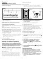
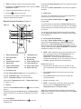
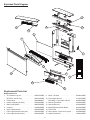
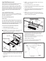
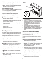
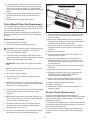
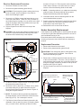
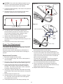
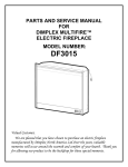
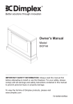
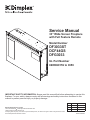
Service Manual
33” Wide Screen Fireplace
with Full Feature Remote
Model Number
DF3033ST
DCF44GS
DFG3033
UL Part Number
6905060159 to 0359
IMPORTANT SAFETY INFORMATION: Always read this manual first before attempting to service this
fireplace. For your safety, always comply with all warnings and safety instructions contained in this
manual to prevent personal injury or property damage.
Dimplex North America Limited
1367 Industrial Road Cambridge ON Canada N1R 7G8
1-888-346-7539 www.dimplex.com
In keeping with our policy of continuous product development, we reserve the right to make changes without notice.
© 2011 Dimplex North America Limited
REV
PCN
Date
00
11534
Jul 22, 09
01
11622
Sep 11, 09
02
12974
Aug 31, 11
7400210000R02
Table of Contents
Operation. . . . . . . . . . . . . . . . . . . . . . . . . . . . . . . . . . . . . . . . . . . . . . . . . . . . . . . . . . . . . . . . . . . . . . . . 3
Exploded Parts Diagram. . . . . . . . . . . . . . . . . . . . . . . . . . . . . . . . . . . . . . . . . . . . . . . . . . . . . . . . . . . . 5
Replacement Parts List. . . . . . . . . . . . . . . . . . . . . . . . . . . . . . . . . . . . . . . . . . . . . . . . . . . . . . . . . . . . . 5
Wiring Diagram. . . . . . . . . . . . . . . . . . . . . . . . . . . . . . . . . . . . . . . . . . . . . . . . . . . . . . . . . . . . . . . . . . . 6
Light Bulb Replacement . . . . . . . . . . . . . . . . . . . . . . . . . . . . . . . . . . . . . . . . . . . . . . . . . . . . . . . . . . . . 7
Mirror Replacement. . . . . . . . . . . . . . . . . . . . . . . . . . . . . . . . . . . . . . . . . . . . . . . . . . . . . . . . . . . . . . . . 8
Main On/Off Switch Replacement. . . . . . . . . . . . . . . . . . . . . . . . . . . . . . . . . . . . . . . . . . . . . . . . . . . . . 8
Switch Board Replacement. . . . . . . . . . . . . . . . . . . . . . . . . . . . . . . . . . . . . . . . . . . . . . . . . . . . . . . . . . 9
Flicker Motor/Flicker Rod Replacement . . . . . . . . . . . . . . . . . . . . . . . . . . . . . . . . . . . . . . . . . . . . . . . 10
Remote Control Replacement. . . . . . . . . . . . . . . . . . . . . . . . . . . . . . . . . . . . . . . . . . . . . . . . . . . . . . . 10
Heater Assembly Replacement. . . . . . . . . . . . . . . . . . . . . . . . . . . . . . . . . . . . . . . . . . . . . . . . . . . . . . 11
Power Cord Replacement. . . . . . . . . . . . . . . . . . . . . . . . . . . . . . . . . . . . . . . . . . . . . . . . . . . . . . . . . . 12
Troubleshooting Guide . . . . . . . . . . . . . . . . . . . . . . . . . . . . . . . . . . . . . . . . . . . . . . . . . . . . . . . . . . . . 13
2
Operation
interference with other units.
Electric Fireplace Manual Control
Battery Installation
The manual controls for the fireplace are located in the upper
right hand corner (Figure 1).
Figure 1
C
B
1. Depress tab on the battery cover on the back of the
remote transmitter and remove battery cover (Figure 2).
Figure 2
A
Batteries
Unlocked
Locked
Child Lock Tab
Child Lock
2. Install two (2) AAA batteries into the remote control
(originally included).
A. Main On/Off Switch
Supplies power to the 3 position manual control switch.
3. Ensure child lock is in the “unlocked” position.
4. Replace the battery cover.
B. 3 Position Manual Control Switch
! NOTE: When the “BAT” symbol is present on the remote
Remote (left position): The unit is operated with the remote
control.
control it is recommended to replace the batteries
promptly, to maintain full functionality of the remote/
fireplace. The remote transmitter has a battery backup
time of only several hours.
Flame (center position): The flame effect is turned ON.
Flame & Heat (right position): The flame effect and heater
are turned ON simultaneously. When the manual control is
in the Flame & Heat position the heater does not run on the
remote operated thermostat.
Initializing The Remote Control
1. Plug cord into 120 Volt wall outlet.
! NOTE: When the manual control switch is in the Flame
2. Ensure the Main On/Off switch located in the switch box
on the fireplace in the upper right hand corner is in the
ON position.
and Flame & Heat positions, the fireplace unit will not
operate with the remote control.
C. Initialization Button
3. Set the 3 position manual control to the Remote position
(left position).
Used to synchronize the remote control.
4. Press and hold the Initialization Button on the unit.
Resetting The Temperature Cutoff Switch
5. While holding the Initialization Button, press the
button on the remote control
Flame/Heat ON/OFF
transmitter.
Should the heater overheat, an automatic switch will turn the
heater off and it will not come back on without being reset.
The temperature cutoff switch can be reset by unplugging the
unit, waiting five (5) minutes and plugging the unit back in.
6. Release the Initialization Button on the unit.
7. Press the Flame/Heat On/Off button
Heat function on.
CAUTION: If you need to continuously reset the heater,
unplug the unit and call Dimplex North America Limited
at 1-888-346-7539. Please have your model and serial
number ready when calling.
to turn the Flame/
Frequency Interference
If the fireplace does not respond properly to the remote
control, the remote operating frequency may have to be
reset. The remote control can send another frequency code
to the circuit board to eliminate interference.
Remote Control
The remote control has a range of approximately 50 feet
(15.25 m), it does not have to be pointed at the fireplace
and can pass through most obstacles (including walls). It
is supplied with 243 independent frequencies to prevent
1. Simultaneously press the “Temperature Down” button
and the “Flame Speed Down” button on the remote
control.
3
Press the 12. Flame Speed Up button to increase the speed
of the flame.
2. “COD” will appear in place of the sleep timer digits.
3. Release the “Temperature Down” button and the “Flame
Speed Down” button.
Press the 11. Flame Speed Down to decrease the speed of
the flame.
4. Press the Initialization Button on the unit.
5. Press the
5. Sleep Timer
button on the remote.
Your remote will now have a different frequency
communicating with the fireplace.
The Sleep Timer automatically shuts off the fireplace after a
preset time (from 30 minutes to 8 hours).
Remote Control Functions (Figure 3)
Press the 6. Flame & Heat On/Off button
fireplace ON.
Figure 3
2
9
11
To set the sleep timer press the 14. Sleep Timer Up button.
1
7
Set the timer from 30 minutes through 8 hours. The fireplace
will automatically turn off when the sleep timer reaches zero
(0) minutes.
8
3
12
The sleep timer can be cancelled at any time by pressing
the 13. Sleep Timer Down button repeatedly until the sleep
timer displays “0”.
14
6. Flame & Heat On/Off Button
10
4
13
to turn the
Press the 6. Flame & Heat On/Off button
Flame/Heat function ON. When 2. Set Temperature is
higher then 1. Room Temperature the heat will come on.
To turn the heat off, lower the 2. Set Temperature so that it’s
setting is lower then the 1. Room Temperature. The default
temperature setting is 72°F (22°C).
5
6
to turn the
! NOTE: When using the remote control the heater runs
1.
2.
3.
4.
5.
6.
7.
Room Temperature
Set Temperature
Dimmer
Flame Speed Control
Sleep Timer
Flame & Heat On/Off
Temperature Down
8.
9.
10.
11.
12.
13.
14.
on a thermostat. Press the 8. Temperature Up or 7.
Temperature Down buttons to adjust the set
temperature. Once the desired set temperature is
reached the heater will turn off. The heater will cycle on
and off to maintain the desired set temperature.
Temperature Up
Dimmer Down
Dimmer Up
Flame Speed Down
Flame Speed Up
Sleep Timer Down
Sleep Timer Up
Child Lock (Figure 2)
1. Depress tab on the battery cover on the back of the
remote transmitter and remove the battery cover (Figure
5).
2. Set Temperature
2. Move Child Lock tab to the right to lock the remote
transmitter.
Press 6. Flame & Heat On/Off button to turn fireplace on.
Press 8. Temperature Up to raise thermostat.
3. Move Child Lock tab back to the left to unlock the
remote transmitter.
Press 7. Temperature Down to lower thermostat.
4. Replace the battery cover.
Press both 8. Temperature Up and 7. Temperature Down
to change °F to °C.
! NOTE: To temporarily unlock the remote transmitter
press (in order) 7. Temperature Down then 8.
Temperature Up then 9. Dimmer Down.
3. Dimmer
Press the 6. Flame/Heat On/Off button
Heat on.
to turn the Flame/
When the remote transmitter’s backlight is illuminated the
Child Lock is bypassed. When the backlight is off the Child
Lock is re-activated.
Repeatedly press the 10. Dimmer Up or 9. Dimmer Down
button to decrease or increase the brightness of the upper
lights.
4. Flame Speed
Press the 6. Flame & Heat On/Off button
Flame/Heat on.
to turn the
4
Exploded Parts Diagram
13
3
4
6
12
9
1
5
7
10
8
11
14
2
Replacement Parts List
Replacement Part:
1. 30” Urethane Log Set. . . . . . . . . . . . . . . . .
DFG3033 - Media Tray. . . . . . . . . . . . . . . .
2. Flicker Motor . . . . . . . . . . . . . . . . . . . . . . .
3. Heater Assembly (w/cutout) . . . . . . . . . . . .
4. Main On/Off Switch . . . . . . . . . . . . . . . . . .
5. Cord Set . . . . . . . . . . . . . . . . . . . . . . . . . . .
6. Upper Light Harness. . . . . . . . . . . . . . . . . .
7. Lower Light Harness (outer pair) . . . . . . . .
8. Lower Light Socket (center) . . . . . . . . . . . .
0439070100RP
0440410100RP
3000240200KIT
2000330200RP
2800070200RP
4100040300RP
2500400200RP
2500400100RP
2500150200RP
9. Mirror - Silvered . . . . . . . . . . . . . . . . . . . . .
10. Front Glass with trim. . . . . . . . . . . . . . . . . .
DCF44GS - Front Glass with trim. . . . . . . .
11. Remote Transmitter . . . . . . . . . . . . . . . . . .
12. Remote Receiver . . . . . . . . . . . . . . . . . . . .
13. Manual/Remote Switch Board . . . . . . . . . .
14. Flicker Rod . . . . . . . . . . . . . . . . . . . . . . . . .
15. Wire Harness - Reciever to Logset. . . . . . .
16. Glass Rock Media. . . . . . . . . . . . . . . . . . . .
5
5900910100RP
1015270159RP
6905870200RP
3000350100RP
3000300200RP
3000300300RP
5901250100RP
2500380200RP
1400070100RP
Wiring Diagram
Main On/Off
Switch
Cord Set
Heater
Assembly
Remote
Receiver
Flicker
Motor
Log Set
6
! NOTE: Log Set fits tightly into firebox, some force may
Light Bulb Replacement
be necessary to remove.
Allow at least five (5) minutes for light bulbs to cool before
touching bulbs to avoid accidental burning of skin.
4. Set Log Set/ Media Tray in front of fireplace.
Light bulbs need to be replaced when you notice a dark
section of the flame or when the clarity and detail of the log
Ember Bed exterior disappears. There are three (3) bulbs
under the Log Set, which generate the flames and embers,
and two (2) bulbs above the log that illuminate the log
exterior.
5. Disconnect the Log Set LED wire harness from unit. (Not
present on Media Tray)
6. Gently pull the Flicker Rod to the right as far as possible
into the rubber bushing on the Flicker Motor shaft
(Figure 5).
! NOTE: When removing the Flicker Rod, damage may
occur if bent excessively. If the Flicker Rod is damaged,
replace to insure proper operation.
Lower Light Bulb Requirements
Quantity of three (3) clear chandelier or candelabra bulbs
with an E-12 (small) socket base, 60 Watt rating. Example:
GE 60BC or Philips 60 CTC.
Do not exceed 60 Watts per bulb
Figure 5
Helpful Hints
Exploded view to show detail
Light Filter
Bracket
It is a good idea to replace all light bulbs at one time if they
are close to the end of their rated life. Group replacement
will reduce the number of times you need to open the unit to
replace light bulbs. Care must be taken when removing the
Log Set as the Log Set contains LED’s and wires.
Flicker Motor
Shaft and rubber
bushing
Flicker
Motor
Screws to
remove
(2 per side)
To access the lower light bulb area (Figure 4):
1. Slide fireplace out from mantel.
2. Remove front glass assembly (glass lifts off).
Bulbs (3)
CAUTION: Even though the glass is safety glass it may
break if bumped, struck of dropped. Care must be
taken when handling the glass.
Flicker Rod
7. Cautiously bend the Flicker Rod enough so that the
remaining end of the Flicker Rod clears the plastic
bushing on the left (Figure 5).
Figure 4
Upper Bulbs
8. Remove the Light Filter Bracket by unscrewing four (4)
Philips screws as shown in Figure 5.
9. Replace bulb(s) as needed.
Media Tray or Log Set
(depending on model)
10.Reinstall the Light Filter Bracket and Flicker Rod.
11. Reconnect the Log Set LED wire harness.
Figure 6
Lower
Bulbs
Front
Glass
LED
Wire Harness
3. Pull the front edge of the plastic Ember Bed, plastic grate
or Media Tray (depending on Model) up and forward until
the rear tab releases from the ledge located at the bottom
of the mirror.
Rear
Tab
! IMPORTANT: Only handle the Log Set by the Ember
Log
Ember Bed
Back
Ledge
Side Section
Bed.
7
Front
Edge
12. Replace the Log Set by inserting the front edge of the
fireplace and push down on the rear edge of the Ember
Bed until it snaps into place (Figure 6).
Figure 7
! NOTE: Ensure the Log Set is installed tightly under the
back ledge to prevent light leakage.
Mirror
Upper Light Bulb Requirements
Clamp (2)
Quantity of two (2) clear chandelier or candelabra bulbs with
an E-12 (small) socket base, 15 Watt rating.
Do not exceed 15 Watts per bulb
To access the upper light bulb area (Figure 4):
1. Remove front glass assembly (glass lifts off).
CAUTION: Even though the glass is safety glass it may
break if bumped, struck of dropped. Care must be
taken when handling the glass.
5. Disconnect the Log Set LED wire harness from unit
(Figure 4, Page 7).
2. Upper bulbs are located in the upper left and upper right
corners of fireplace (Figure 4).
6.
7.
Loosen but do not remove the two (2) Philips screws
that clamp the mirror in place, and swivel down so that
the clamp clears the edge of the mirror (Figure 7).
Push the mirror out from behind to clear the frame and remove.
8. Insert replacement mirror top end first and lay the bottom end gently in the bottom track of the frame.
9. Swivel the clamps back into place. Tighten clamps and
reassemble fireplace in reverse order as described
above.
3. Remove the upper light cover for each bulb (two (2)
Philips screws each).
4. Unscrew bulbs counter clockwise.
5. Insert new bulbs.
6. Re-install upper light bracket.
7. Replace glass assembly.
Mirror Replacement
Main On/Off Switch Replacement
If the fireplace was operating prior to servicing allow at least
10 minutes for light bulbs and heating element to cool off to
avoid accidental burning of skin.
Disconnect power before attempting any maintenance or
cleaning to reduce the risk of electric shock or damage to
persons.
If the fireplace was operating prior to servicing allow at least
10 minutes for light bulbs and heating element to cool off to
avoid accidental burning of skin.
Disconnect power before attempting any maintenance or
cleaning to reduce the risk of electric shock or damage to
persons.
Replacement Procedure
Main On/Off Switch Replacement Procedure:
1. Slide fireplace out from mantel.
2. Remove front glass assembly (glass lifts off).
1. Remove the firebox from the mantel.
2. Remove front glass assembly (glass lifts off).
CAUTION: Even though the glass is safety glass it may
break if bumped, struck of dropped. Care must be
taken when handling the glass.
CAUTION: Even though the glass is safety glass it may
break if bumped, struck of dropped. Care must be
taken when handling the glass.
3. Pull the front edge of the plastic Ember Bed or plastic
grate up and forward until the rear tab releases from the
ledge located at the bottom of the mirror.
3. Remove the 10 Philips screws that fasten the top cover
to the rest of the firebox. There are: two (2) screws on
each side along the top edge; four (4) screws on the back
along the top edge, and two (2) screws on the top of the
fireplace (see Figure 8, Page 9).
4. Flip the top panel over and rest it on the top of the
fireplace, across the rear half of the unit.
! IMPORTANT: Only handle the Log Set by the Ember
Bed.
! NOTE: Log Set fits tightly into firebox, some force may
be necessary to remove.
CAUTION: Use caution when flipping top panel over as
there are components attached to the top panel which
are wired to the internal cavity of the fireplace.
4. Set Log Set in front of fireplace.
8
Switch Board Replacement
Figure 8
If the fireplace was operating prior to servicing allow at least
10 minutes for light bulbs and heating element to cool off to
avoid accidental burning of skin.
Disconnect power before attempting any maintenance or
cleaning to reduce the risk of electric shock or damage to
persons.
Top Cover
Replacement Procedure
1. Remove the firebox from the mantel.
2. Remove front glass assembly (glass lifts off).
CAUTION: Even though the glass is safety glass it may
break if bumped, struck of dropped. Care must be
taken when handling the glass.
Baffle and Switch
Mount Bracket
3. Remove the 10 Philips screws that fasten the top cover
to the rest of the firebox. There are: two (2) screws on
each side along the top edge; four (4) screws on the back
along the top edge, and two (2) screws on the top of the
fireplace (see Figure 8, Page 9).
4. Flip the top panel over and rest it on the top of the
fireplace, across the rear half of the unit.
- Screws To Remove for Top Cover
- Screws to Remove for Baffle (3 per side)
5. Referring to Figure 8, remove the three (3) Philips screws
on each side of the fireplace to release the Baffle and
Switch Mount Bracket (six (6) screws in total).
6. Flip the Baffle and Switch Mount Bracket over and rest it
across the front half of the fireplace.
Figure 9
CAUTION: Use caution when flipping top panel over as
there are components attached to the top panel which
are wired to the internal cavity of the fireplace.
5. Referring to Figure 8, remove the three (3) Philips screws
on each side of the fireplace to release the Baffle and
Switch Mount Bracket (six (6) screws in total).
6. Flip the Baffle and Switch Mount Bracket over and rest it
across the front half of the fireplace.
7. Locate the Switch Board mounted on the underside
of the Baffle panel on the right side (Figure 10) and
disconnect the white wire harness that leads to the main
circuit board.
Underside of Baffle and
Switch Mount Bracket
Main On/Off
Switch
Figure 10
Underside of Baffle and
Switch Mount Bracket
Retainer Clips (one per side)
7. Locate the Main On/Off Switch mounted on the underside
of the Baffle panel on the right side (Figure 9) and
disconnect the two (2) wiring clips noting their original
locations.
5. Depress the two (2) retainer clips on the sides of the
switch and push the switch out of the bracket.
6. Properly orient the new switch and the wiring clips as
before.
7. Reassemble in the reverse order as above.
Switch Board
Mounting Studs (one per side)
9
8. The Switch Board is fastened to the underside of the
Baffle and Switch Mount Bracket by two (4) mounting
studs, one on each side (Figure 10). Squeeze both
mounting stud’s clasp to release and remove the Switch
Board.
6. Properly orient the new Switch Board, snap onto the
mounting studs and reconnect the wire harness as
before.
7. Reassemble in the reverse order as above.
Figure 11
Flicker Motor Shaft and
Rubber Bushing
Flicker Motor/Flicker Rod Replacement
Screws to
remove (2)
Flicker
Rod
If the fireplace was operating prior to servicing allow at least
10 minutes for light bulbs and heating element to cool off to
avoid accidental burning of skin.
Disconnect power before attempting any maintenance or
cleaning to reduce the risk of electric shock or damage to
persons.
Flicker Motor
9. Before removing the Flicker Motor, cut the Flicker Motor
wires (five (5) in total) close to the Flicker Motor end
with wire cutters.
10.Remove the rubber bushing from the motor shaft by
applying needle nose pliers to the motor shaft and twist
the rubber bushing off of the motor shaft.
11. Remove the motor by unscrewing the two (2) Philips
screws that attach the motor to the mounting bracket
(Figure 11).
11. Discard old Flicker Motor.
Replacement Procedure:
1. Slide fireplace out from mantel.
2. Remove front glass assembly (glass lifts off).
CAUTION: Even though the glass is safety glass it may
break if bumped, struck of dropped. Care must be
taken when handling the glass.
12.Pick up new Flicker Motor and cut wire leads to 3 1/2
inch long with wire cutters.
13.Using one of the supplied wire connectors from the
Replacement Part Kit, place one (1) yellow wire from
the new Flicker Motor and the yellow wire cut in step 9
into each terminal.
14.Secure the wire connector by crimping the 3M symbol
with pliers.
15. Pull on end of wires to ensure a strong connection.
16. Repeat the process for the four (4) remaining wires.
ENSURE THAT ALL WIRES ARE PAIRED BY
COLOUR IN EACH CONNECTOR.
17.Properly orient and secure the replacement Flicker
Motor to the bracket with screws removed in step 9.
18.Replace rubber bushing on motor shaft.
19.Replace Flicker Rod.
20.Reassemble firebox in reverse order as above and
replace in mantel.
3. Pull the front edge of the plastic Ember Bed or plastic
grate up and forward until the rear tab releases from the
ledge located at the bottom of the mirror.
! IMPORTANT: Only handle the Log Set by the Ember
Exploded view to show detail
Bed.
! NOTE: Log Set fits tightly into firebox, some force may
be necessary to remove.
4. Set Log Set in front of fireplace.
5. Disconnect the Log Set LED wire harness from unit
(Figure 4, Page 7).
! NOTE: When removing the Flicker Rod, damage may
occur if bent excessively. If the Flicker Rod is damaged,
replace to insure proper operation.
6. Gently pull the Flicker Rod to the right as far as possible
into the rubber bushing on the Flicker Motor shaft
(Figure 11).
Remote Control Replacement
Remote Control hand held transmitters require no
replacement procedure however, a re initialization procedure
may need to be followed. Refer to Page 3 for the Remote
Initialization procedure.
If the fireplace was operating prior to servicing allow at least
10 minutes for light bulbs and heating element to cool off to
avoid accidental burning of skin.
Disconnect power before attempting any maintenance or
cleaning to reduce the risk of electric shock or damage to
persons.
! NOTE: When removing the Flicker Rod, damage may
occur if bent excessively. If the Flicker Rod is damaged,
replace to insure proper operation.
7. Cautiously bend the Flicker Rod enough so that the
remaining end of the Flicker Rod clears the plastic
bushing on the left (Figure 11).
8. Remove Flicker Rod (replace and reassemble if Flicker
Motor does not need to be changed at this point).
10
Receiver Replacement Procedure:
as shown in Figure 12. Either squeeze each mounting
stud’s clasp to release, or use side cutters to cut and
remove each of the Mounting Studs on the board.
1. Remove the firebox from the mantel.
2. Remove front glass assembly (glass lifts off).
! NOTE: If mounting studs are cut, replacement mounting
studs will need to be inserted through the top panel.
Replacement Mounting Studs are supplied.
CAUTION: Even though the glass is safety glass it may
break if bumped, struck of dropped. Care must be
taken when handling the glass.
8. Clear both ends of each cut Mounting Stud from the
control board and the top panel.
9. Properly orient the new Remote Control Receiver Board
and re-connect all of the wiring connections (refer to
notes taken in step 6 and Figure 12).
10.Reassemble in the reverse order as above.
3. Remove the 10 Philips screws that fasten the top cover
to the rest of the firebox. There are: two (2) screws on
each side along the top edge; four (4) screws on the back
along the top edge, and two (2) screws on the top of the
fireplace (see Figure 8, Page 9).
4. Flip the top panel over and rest it on the top of the
fireplace.
Heater Assembly Replacement
CAUTION: Use caution when flipping top panel over as
there are components attached to the top panel which
are wired to the internal cavity of the fireplace.
If the fireplace was operating prior to servicing allow at least
10 minutes for light bulbs and heating element to cool off to
avoid accidental burning of skin.
Disconnect power before attempting any maintenance or
cleaning to reduce the risk of electric shock or damage to
persons.
Figure 12
Replacement Procedure
1. Remove the firebox from the mantel.
2. Remove front glass assembly (glass lifts off).
Mounting
Studs (7)
Blue wire to Heater
Assembly
CAUTION: Even though the glass is safety glass it may
break if bumped, struck of dropped. Care must be
taken when handling the glass.
Antenna
Wire
3. Remove the 10 Philips screws that fasten the top cover
to the rest of the firebox. There are: two (2) screws on
each side along the top edge; four (4) screws on the back
along the top edge, and two (2) screws on the top of the
fireplace (see Figure 8, Page 9).
4. Flip the top panel over and rest it on the top of the
fireplace.
Orange wire
to Main On/
Off Switch
White wire
to lower
section
Figure 13
Blue wire from top terminal of
element to right terminal of motor
White ribbon
cable to Switch
Board
Black wire from top
terminal to Remote
Board
Motor
5. Locate the Remote Control Receiver on the right side of
the upturned top panel (Figure 12).
6. Remove the one (1) blue, one (1) orange, one (1) white
wire leads and three (3) cable connectors from the
Remote Control Receiver Board as shown in Figure 15,
noting their original locations.
Element
! NOTE: The Antenna Wire is permanently attached to
the fixed daughter card of the Remote Control Receiver
Board (Figure 12). Do not attempt to remove.
7. The Remote Control Receiver Board is fastened to the
underside of the top panel by seven (7) Mounting Studs,
one (1) in each corner, and three (3) down off center
Blue wire from Remote Board
to bottom terminal of element
11
Orange wire from
bottom terminal of
right side element to
left terminal of motor
CAUTION: Use caution when flipping top panel over as
there are components attached to the top panel which
are wired to the internal cavity of the fireplace.
Figure 15
Screws (2)
5. Locate the Heater Assembly in the center of the upturned
top panel (Figure 13).
6. Disconnect all six (6) wire connections on the Heater
Assembly, noting all of their original positions.
Figure 14
Figure 16
Screws to remove (5)
Wire connectors (2)
6.
7.
8.
Turn the top panel over and while supporting the
Heater Assembly and panel in one hand, remove the
five (5) heater mounting screws, noting the center
screw is of a larger diameter (Figure 14).
Separate the Heater Assembly from the top panel.
Properly orient the new Heater Assembly and
re-connect all of the wiring connections (use Figure 13 as
reference).
9. Reassemble in the reverse order as above.
Power
Cord
Access
Panel
Wire clamp
Power Cord Replacement
If the fireplace was operating prior to servicing allow at least
10 minutes for light bulbs and heating element to cool off to
avoid accidental burning of skin.
Disconnect power before attempting any maintenance or
cleaning to reduce the risk of electric shock or damage to
persons.
access panel and secure with clamp.
10.The wide blade of the power plug is designed to be
live and is connected to the cord side with ridges in the
rubber of the cord. Use one of the wire connectors from
step 8 to connect this side of the Power Cord with the
white live line from the firebox.
The other side of the Power Cord will have stamped
writing in the rubber sheath. Use the second wire
connector from step 8 to connect this side of the Power
Cord with the black neutral line from the firebox.
11. Place cord slack back into the firebox chassis and
reattach the Power Cord Access Panel with the two (2)
Philips screws removed in step 3.
12.Replace firebox back into mantel and plug in.
Replacement Procedure:
1. Remove the firebox from the mantel.
2. Turn unit so that the right, rear corner of the fireplace is
most accessible.
3. Remove the two (2) Philips screws that fasten the Power
Cord Access Panel to the rest of the firebox (Figure 15).
5. Pull the access panel away from the firebox and pull
enough slack of power cord from within the firebox to
work with. Use caution as the power cord is connected
to internal components (Figure 16).
6. Using pliers, squeeze the sides of the plastic wire clamp
on the inside of the Access Panel and push it through the
panel.
7. Release clamp from power cord.
8. Unscrew the two (2) wire connectors as shown in Figure
16. The power cord is now able to be fed through the
access panel and set aside.
9. Feed replacement power cord through opening in the
12
Troubleshooting Guide
Problem
Cause
Solution
General
Circuit breaker trips or fuse
blows when unit is turned on
Short in unit wiring.
Trace wiring in unit.
Improper circuit current rating
Additional appliances may exceed the current rating of
the circuit breaker or fuse. Plug unit into another outlet or
install unit on a dedicated 15 amp circuit.
Unit turns on or off by itself
Remote control has a similar frequency
to other remotes in the area.
Replace Remote Control
Radio frequency disturbance from outside sources.
Replace hand held remote control and receiver board
where necessary.
Defective circuit board
Replace circuit board
Lights dim in room while the unit
is on
Unit is drawing close to circuit current
rating
Move the unit to another outlet or install unit on a dedicated 15 amp circuit
Power cord gets warm
Normal Operation
The power cord may get slightly warm to the touch when
the heater is on
Defective power cord
Replace power cord if cord gets hot to the touch.
Improper operation
Improper operation
No incoming voltage from the electrical
wall socket
Check Fuse/Breaker Panel
Loose wiring
Check wiring connections
Defective main on/off switch
Replace main on/off switch
Defective circuit board
Replace circuit board
Improper operation
Improper operation
Remote control not initialized to fireplace
Initialize the remote control
Defective remote control
Install new battery into the handheld transmitter. Reconfigure remote where necessary
Appearance
Fireplace does not turn on in
Manual Mode
Fireplace does not turn on with
Remote
Replace remote control circuit board where necessary
Defective remote control switch
Replace remote control switch board
Defective circuit board
Replace circuit board
Flame Frozen
Defective flame motor
Replace flame motor
Loose wiring
Check wiring connections
Flame not bright or flame not
visible
Burnt light bulbs
Replace light bulbs
Loose wiring
Check wiring connections
Defective light harness
Replace light harness
Log set dim, not glowing
Burnt light bulbs
Replace light bulbs
Flame Shutter
Defective flame motor
Replace flame motor
Light leaking around the log set
Log set not positioned properly
Check log set for proper fit
Improper operation
Refer to Operation Section
Defective heater on/off switch
Replace heater on/off switch
Loose wiring
Trace wiring in unit
Defective remote control
Replace remote control
Defective circuit board
Replace circuit board
Heater
Heater is not turning off
13
Problem
Cause
Solution
Heater Continued
Heater is not turning on
Improper operation
Refer to Operation Section
Defective heater assembly
Replace heater assembly
Defective heater on/off switch
Replace heater on/off switch
Heater is turning off after a
couple of minutes of operation
Build up of dirt/dust in heater assembly
Clean out heater assembly
Defective Motor
Replace Motor
Heater emits an odor
Normal Operation
Normal operation is when the heater emits an odor for
a brief period after the heater is initially turned on. The
heater is burning off any dust accumulated during manufacturing or operation.
Defective heater assembly
Replace heater assembly
Heater fan turns on but heater
lacks heat
Improper operation
Refer to Operation Section
Defective thermostat
Replace thermostat
Loose wiring
Trace wiring in unit
Defective heater assembly
Replace heater assembly
Normal Operation
Small glowing sections of the element are considered
normal.
Defective heater assembly
If larger glowing sections are causing the heater to trip the
thermal cutout, unplug unit, discontinue use and replace
heater assembly.
Loose wiring
Trace wiring in unit
Defective heater on/off switch
Replace heater on/off switch
Defective heater assembly
Replace heater assembly
Defective thermostat
Replace thermostat
Excessive noise with the heater
on
Dirty blower assembly
Clean blower assembly
Defective blower assembly
Replace heater assembly
Grinding or excessive noise with
the heater off
Moving flame rod hitting or rubbing
against internal components
Ensure rod is straight and mounted properly in the bracket, spinning freely away from other components. Replace
if necessary.
Defective flame motor
Replace flame motor
Heating element is glowing red
Heater fan runs continuously
Noise
14