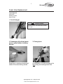
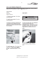
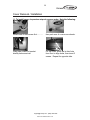
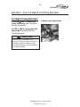
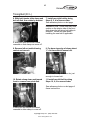
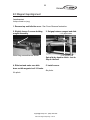
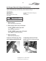
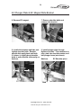
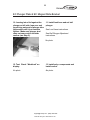
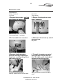
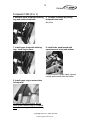
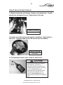
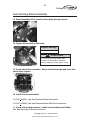
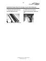
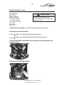
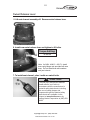
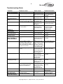
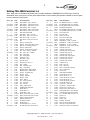
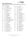
1
®
NuStep TRS 4000
Recumbent Cross Trainer
Service Manual Complete
ii
TRS 4000
HOW TO OBTAIN CUSTOMER SUPPORT AND PARTS
STEP 1
Identify the problem.
Speak with the person who reported the problem to get a good understanding of the problem.
STEP 2
Verify the problem on the NuStep stepper.
Use this manual to verify and/or service the problem and/or determine what parts are required.
STEP 3
Record the serial number of the NuStep stepper and the cumulative steps taken.
The serial number is located at the top end of the electronic tube directly behind the display.
The display has a “stepmeter” that shows cumulative steps. To show the steps, press and hold
the reset button and then press the “up” arrow while continuing to hold the reset button.
Read the cumulative steps across the HEART RATE, METS/WATTS and WORKLOAD LCD
screens. There will be a total of 9 digits and the value is displayed for 5 seconds. Repeat if
necessary.
STEP 4
Contact Customer Support at NuStep Inc.
To support our customers better, you must have the serial number, cumulative steps,
complete description of the problem, and part or item number(s) required to service the
problem for our product specialists.
Our Product Specialists are ready to help you 8:00 a.m. - 4:30 p.m. EST.
Email, Call, or Fax Customer Support at:
Email
[email protected]
Phone:
(800) 322-4434 or (734) 769-3939 x 5
Fax:
(734) 769-8180
Address:
NuStep Inc.
5111 Venture Dr. Ste. 1
Ann Arbor MI 48108-1654
International customers may obtain customer support by contacting their local NuStep distributor.
NuStep® is a registered trademark of NuStep, Inc.
United States Patent Nos. 5,356,356, 6,361,479 B1, 6,042,518, 6,666,799, D359,777, D421,075, and
other patents pending.
TRS4000 Service Manual P/N 41904B
Copyright May 2005 by NuStep, Inc. All rights reserved.
The information in this manual is the most current at the time of printing. Due to our commitment toward
continuous improvement, specifications and descriptions are subject to change without notice. No part of
this manual may be reproduced or transmitted in any form or by any means, electronic or mechanical, for
any purpose without the express written permission of NuStep, Inc.
[email protected] - (800) 322-4434
[email protected] - (800) 322-4434 - (734) 769-3939 x 5
iii
TRS 4000
ABOUT THIS MANUAL
Your NuStep is made with high quality components designed for long life and durability. In the
event the NuStep needs service, this manual provides some information for a mechanically
qualified person to service it. The following important items tell more about the manual.
Service Manual Coverage
This Service Manual - Complete covers NuStep TRS4000 products built beginning in 1999.
Service Instructions
We hope you like the digital photos that show how to perform the service. Each instruction begins
with a helpful list of required tools that you will need to complete the job. Please follow the Steps
in order. The major instruction steps are above the photos while others are directly below the
photos. Please read NOTES and GOTO instructions carefully. They contain important
information to save you time and direct you to the next applicable step.
Finally, solid arrows
usually point toward the part/action described, while
dotted line arrows
indicate direction of movement.
Directional References
All directional references -- left, right, front, back, side, top, bottom -- are from a user’s perspective
as if sitting on the seat of the NuStep, unless noted. Please note that these directional references
still refer back to the original reference, even when the NuStep is placed on its side.
Part Names, Part Numbers, and Item Numbers
Please match parts from the digital photos to the Schematic Drawings and Parts List to obtain
Item and Part Numbers.
Operating Instructions
This service manual does not include operating instructions. The NuStep TRS4000 Operating
Manual is sent with each NuStep. Additional copies can be obtained from NuStep Inc.
!
CAUTION
This is the safety alert symbol. It is used
to call attention to instructions
concerning personal safety. Read and
obey all safety messages that follow
this symbol to avoid possible injury or
death resulting from misuse.
!
CAUTION
The TRS 4000 is very heavy; it weighs
205 lbs (93 kg). To avoid injury, or
damage to the product, always obtain
assistance to move this product.
Use proper lifting technique.
!
CAUTION
CAUTION indicates a potentially
hazardous situation, which if not
avoided, may result in minor or
moderate injury. It may also be used to
alert against unsafe practices.
!
CAUTION
Do not operate this product unless all
covers, guards, and parts are in place
and securely fastened.
Do not operate this product if it appears
damaged or inoperable.
[email protected]
[email protected]
- (800) 322-4434
- (800) -322-4434
(734) 769-3939 x 5
iv
TRS 4000
Preventive Maintenance
Break-In Period, Preventive Maintenance Intervals
Break-in Period
Most mechanical products “break-in” after which bearings roll more freely, bushings rotate better,
belts stretch, and parts loosen up a little. This is normal. Your TRS4000 is designed to
accommodate this “break-in” with no adjustment on your part. The resulting effect is that there is
a little less friction and the unit may feel a little easier, but this is normal and the unit needs no
calibration.
Preventive Maintenance Intervals
Your TRS4000 is designed to be maintenance free. We recommend just a few items that will
increase the useful life of the NuStep. Please follow the recommended preventive maintenance
intervals (in months) according to the amount of usage that the NuStep receives (hours per
week). These are estimated intervals and you may need to increase or decrease the time period
between preventive maintenance depending on your actual use.
Preventive
Maintenance
Action
Usage
Low
Less than 10
hours per week
(home)
Clean covers,
arms, seat and
display. Wipe off
perspiration,
dirt and dust.
Monthly
Medium
10–40 hours
per week
(clinical)
Weekly
Supplies
High
More than 40
hours per week
(commercial)
Daily
Clean
Non-abrasive
spray cleaner
like Fantastik®
and a soft
cloth.
(4) AA alkaline
batteries.
Replace
batteries.
Every 12
months
Every 3
months
Every 1
month
Replace
Check drive belts
for signs of wear.
Every 12
to 24
months
Every 6 to
12 months
Every 3 to 6
months
Gently turn
NuStep onto side
and check.
[email protected]
[email protected]
- (800) 322-4434
- (800) -322-4434
(734) 769-3939 x 5
Rechargeable
batteries are not
recommended
due to voltage
requirements of
the display.
None, if no
action required.
Parts, if action
required.
v
TRS 4000
Contents
How to Obtain Customer Support .............................................................................................. ii
About This Manual ...................................................................................................................... iii
Preventive Maintenance
Break-in Period ....................................................................................................................... iv
Preventive Maintenance Intervals .......................................................................................... iv
Service Instructions (The Parts List item # is in parenthesis).
Arms - Upper
Foam Grip (55) Replacement .................................................................................... 1
Upper Arm (1 & 2) ...................................................................................................... 2
Arm Lock (3) .............................................................................................................. 3
Arms - Lower
Arm Lock Knob (70) .................................................................................................. 4
Arm Lock Weldnut Repair Kit .................................................................................... 5
Arm Lock Knob Repair Kit ......................................................................................... 6
Lower Arm (4 & 5) & Bearings (8 & 9) & Pivot Shaft (129) ....................................... 7
Pivot Cam (158) Adjustment ................................................................................... 32
Pivot Cam Removal – see Lower Arm
Cover
Cover Removal/Installation (38 & 39 & 40) ............................................................. 12
Seat Position Indicator Label (72) Replacement .................................................... 15
Display
Battery Changing ..................................................................................................... 16
Display Removal/Installation (43) ........................................................................... 17
Display Accessory Kit Installation (181) .................................................................. 18
Polar Receiver (100) ............................................................................................... 19
Drivetrain
Bearings – Shaft (10) .............................................................................................. 20
Belt Idler Arm (18) ................................................................................................... 22
Belt Idler Spring (136) – see Poly-V Belt & Sheave
Belt Idlers (19) ......................................................................................................... 24
Connecting Link (37) ............................................................................................... 26
Flat Belt (189) & Belt Idler Spring (136) .................................................................. 28
Front Shaft Alignment .............................................................................................. 30
Magnet – EC & Pivot Disks ..................................................................................... 31
Pivot Casting Boot (23) – see Footpedal
Pivot Disk Assembly (99) – call Customer Support @ NuStep Inc
Pivot Shaft (129) – see Lower Arm
Pivot Shaft Alignment .............................................................................................. 33
Poly-V Belt (12) & Sheave (101) & Belt Idler Spring (136) ..................................... 34
Poly-V J6 Flex Belt (12) & Sheave Without Grooves (101) .................................... 36
Rear Shaft (130) & Timing Belt Sprockets (147) ..................................................... 38
Rear Shaft Alignment .............................................................................................. 41
Timing Belt (13 & 14) ............................................................................................... 42
Timing Belt Springs Replacement (139) ................................................................. 46
Timing Belt Sprocket – see Rear Shaft
[email protected]
[email protected]
- (800) 322-4434
- (800) -322-4434
(734) 769-3939 x 5
vi
TRS 4000
Contents
Eddy Current (EC) Magnetic Resistance System
EC Ball Plunger (45) Replacement and Adjustment ............................................... 47
EC Disk (46) & Bearings (7) .................................................................................... 48
EC Magnet (47) ....................................................................................................... 51
EC Magnet Gap Alignment (47) .............................................................................. 52
EC Plunger Plate (50) & EC Magnet Slide Bracket (49) ......................................... 53
Load Lever (75) ....................................................................................................... 56
Workload Level PCB (94) ........................................................................................ 57
Electronics
DC Power Cable (169) ............................................................................................ 58
Hall Effect Sensor (124) .......................................................................................... 60
Ribbon Cable (31) ................................................................................................... 62
VR Sensor (125) ...................................................................................................... 63
Electronic Tube
Display Boot (21) – see Electronic Tube
Electronic Tube (52) ................................................................................................ 65
Electronic Tube Boot (22) – see Electronic Tube
Frame
Main Frame – call Customer Support @ NuStep Inc.
Step Through Support (140) .................................................................................... 67
Wheel (156) & Axle (6) ............................................................................................ 68
Footpedal
Footpedal 1999 (56 & 57) ....................................................................................... 69
Footpedal 2000 (56 & 57) ....................................................................................... 71
Footpedal Bearing Replacement (8) ....................................................................... 73
Footpedal Bumper Upgrade .................................................................................... 74
Footpedal Stabilizer 2000 (161) .............................................................................. 75
Footpedal Support Tube 1999 ................................................................................. 78
Footpedal Support Tube Retaining Ring Removal 1999 (to reduce arm tension) .... 80
Seat
Seat (110) & Swivel (141) & Seat Channel (116) .................................................... 81
Seat Armrest (111) & Seat Armrest Bracket (112 & 113) ........................................ 85
Seat Assembly (115) Removal/Installation .............................................................. 86
Seat Locking Upgrade ............................................................................................. 87
Seat Mounting Bracket Assembly (117) .................................................................. 89
Seat Mounting Bracket (117) & Seat Release Lever Bracket (122)
& Swivel Release Lever Bracket (142) & Springs (135 & 137) & Nyliners (93) ...... 93
Seat Position Indicator (118) ................................................................................... 98
Seat Rail (119) & Seat Stop Pin (123) & Angle Cover Mount Bracket (24) ............ 99
Seat Release Bracket (120) & Seat Release Bracket Spring (138)
& Nyliners (93) ....................................................................................................... 101
Seat Release Bracket With Stud (120) & Seat Release Spring (138) .................. 103
Seat Release Lever (121) ..................................................................................... 107
Seat Wheel (157) .................................................................................................. 109
Swivel Release Lever (143) ................................................................................... 110
Appendix
Troubleshooting Guide ........................................................................................................... A
Parts List 1.4 ........................................................................................................................... C
Figure 1.4 NuStep Assembled View – Part Names ............................................................... E
Figure 2.4 NuStep Exploded Parts View – Outer Part Item Numbers ................................... F
Figure 3.4 NuStep Exploded Parts View – Inner Part Item Numbers .................................... G
[email protected]
[email protected]
- (800) 322-4434
- (800) -322-4434
(734) 769-3939 x 5
1
TRS 4000
Foam Grip Replacement
Tools Required
Utility knife
Rubbing alcohol
Space heater
1. Cut off old grip.
!
CAUTION
To avoid injury, use care when cutting
foam grip.
2. Preheat grip till soft and warm,
pour or spray inside w/ rubbing
alcohol.
3. Push grip on.
Shake grip to distribute alcohol and
shake out excess rubbing alcohol.
A combination of mostly pushing and a
little pulling and twisting works best.
[email protected] - (800) 322-4434
[email protected] - (800) 322-4434 - (734) 769-3939 x 5
42037 Foam Grip Replacement 5-1-05
2
TRS 4000
Upper Arm (R or L)
NOTE: This instruction applies to all variations of arm locks. Make sure to use the
screws that came with the kit if you are installing a complete arm assembly.
Tools Required
Phillips screwdriver
Grease or silicone (white/clear preferred)
1. Loosen knob.
2. Remove 2 screws.
NOTE: If you are installing a new arm
assembly, make sure to use the screws
that came with the kit, not the screws
removed here.
3. Slide cap up arm, and then pull
upper arm out of lower arm tube.
4. To install upper arm, do above
steps in reverse order.
INSTALLATION NOTES:
A. Make sure components are properly
installed before installing arm. NOTE:
arm lock may be either white or black.
B. Wipe a little grease inside top 4" of
lower arm tube before installing. This
prevents squeaking of arm lock & tube.
C. The machine key always faces and
comes in contact with the stud end of
the knob and the holes/indents align
with the screws on the bottom of the
tube. R and L arms tilt inward ~ 20°.
D. When tightening screws in Step 2,
make sure screws go into the holes/
indents on the arm lock, not against it.
The arm lock must float freely. The
screws keep arm lock from coming out.
Reference Picture:
Cap
Machine Key (may be rectangular or
T shaped)
Holes/indents in arm lock that screws
go into (they do not screw into here)
Pin
Arm lock (white or black)
[email protected] - (800) 322-4434
[email protected] - (800) 322-4434 - (734) 769-3939 x 5
42003 Arm - Upper 7-17-00
3
TRS 4000
Arm Lock
Note: This instruction applies to all units, but units with S/N > 411092 use part number 4087
Arm Lock and units with S/N < 411091 use part number 4088 Arm Lock. Part number 4088 has
a “T” shaped machine key.
Tools Required
Hammer
Pliers
Nail punch
Safety glasses
!
CAUTION
To avoid injury, wear safety glasses.
1. Remove upper arm. See Upper Arm instruction.
2. Tap roll pin through first hole.
3. Pull pin from second hole.
4. Remove arm lock and slide new
arm lock onto upper arm.
5. Install roll pin.
To ensure the new arm lock is not installed
backwards, note the machine key’s position relative to the upper arm groove while
removing the arm lock.
6. Install upper arm.
[email protected] - (800) 322-4434
[email protected] - (800) 322-4434 - (734) 769-3939 x 5
42257 Arm Lock 5-1-05
4
TRS 4000
Arm Lock Knob
NOTE: Units with S/N > 411924 do not have a snap ring on the end of the knob stud.
Units < 411924 do, but it is not necessary to reinstall it once removed.
Tools Required
Needle-nosed pliers
Grease/silicone (white/clear)
Safety glasses
!
CAUTION
To avoid injury, wear safety glasses.
1. Remove upper arm. See Upper Arm instruction.
2. Remove snap ring from end of
knob stud if it has one. If not,
continue.
3. Thread old knob out. It may be
hard to thread out if it had a snap
ring on it.
No photo.
4. Lubricate threads on new knob
and thread into arm. Wipe up
excess lube. You do not have to
install snap ring back on.
No photo.
5. Install upper arm per instructions.
No photo.
[email protected] - (800) 322-4434
[email protected] - (800) 322-4434 - (734) 769-3939 x 5
42005 Arm Lock Knob 5-1-05
5
TRS 4000
Arm Lock Weldnut Repair Kit
Note: This instruction applies to units with S/N < 412391. For S/N 411001 - 411091, use part
number 4112. For S/N 411092 - 412391, use part number 4114.
Tools Required
Hammer
Cold chisel
Phillips screwdriver
Torque wrench
Safety glasses
1. Remove upper arm. See Upper
Arm instruction.
!
CAUTION
To avoid injury, wear safety glasses.
2. Install new arm lock. See Arm
Lock instruction.
3. Remove remaining weldnut from
underside of arm weldment (both
weldnuts must be removed to install
the nut plate).
4. Insert nut plate into arm weldment
and align threads with arm
weldment holes. Thread screws into
nut plate until the tip of the screw is
flush with the surface of the nut
plate.
For S/N 411092 - 412391, note the
direction reference written on the nut
plate.
5. Install upper arm. (See Upper Arm
instruction.) Do not over tighten
screws - maximum torque = 7.5 inlbs.
[email protected] - (800) 322-4434
[email protected] - (800) 322-4434 - (734) 769-3939 x 5
42259 Arm Lock Weldnut Repair Kit 5-1-05
6
TRS 4000
Arm Lock Knob Repair Kit
Tools Required
Drill
31/64” drill bit
Tap wrench
9/16” socket and ratchet
9/16” wrench
9/16” - 12 tap
Safety glasses
!
CAUTION
To avoid injury, wear safety glasses.
1. Remove upper arm. See Upper Arm instruction.
2. Remove arm lock knob. See Arm Lock Knob instruction.
3. Drill out arm lock knob hole using
31/64” drill bit.
4. Tap hole using 9/16” - 12 tap.
5. Using the repair kit, thread the 3/8”
- 24 nut all the way onto the bolt, then
thread the threaded insert on the bolt
(make sure slot on threaded insert is
facing the nut and head of bolt).
6. Use the bolt to thread threaded
insert into hole until 1/16” - 1/8” of
the insert sticks out of the end of
hole. Remove bolt leaving threaded
insert in place.
7. Install upper arm. See Upper Arm instruction.
8. Install arm lock knob. See Arm Lock Knob instruction.
[email protected] - (800) 322-4434
[email protected] - (800) 322-4434 - (734) 769-3939 x 5
42261 Arm Lock Knob Repair Kit 5-1-05
7
TRS 4000
Lower Arm (R / L) & Bearings & Pivot Shaft
NOTE: This instruction applies to all units, but units with S/N > 412137 have the
cam shown in Steps 7 & 25 and those lower do not.
Tools Required
½” socket and ratchet
Large flat head screwdriver
5/32" hex key
(3) 2x4 blocks of wood (Very helpful!)
Long Phillips screwdriver
Hard rubber or plastic hammer
Loctite 242
Grease/silicone (white/clear)
Torque wrench
Scratch awl
Safety glasses
1. Remove covers. See Cover
Removal instruction.
!
CAUTION
To avoid injury, wear safety glasses.
2. Disconnect stabilizers or
support tubes from footpedals.
3. Remove step through support.
Remove both footpedals.
See Footpedal 1999 and Footpedal
Support Tube 1999 or Footpedal
2000 and Footpedal Stabilizer 2000
instructions depending on your
model.
4. For S/N < 428173, disconnect
timing belt springs. See Timing Belt
Springs instruction.
5. Remove left and right side nuts
that attach rod ends to arms.
[email protected] - (800) 322-4434
[email protected] - (800) 322-4434 - (734) 769-3939 x 5
42001 Arm - Lower 5-1-05
8
TRS 4000
Lower Arm (R / L) & Bearings & Pivot Shaft
6. Pry off both rod ends with large
screwdriver. Let arms rotate
forward against footpedal bumper.
!
CAUTION
To avoid injury, or damage to the
product, use caution when removing or
installing. Hold arm weldment before
prying rod end off bolt to prevent
weldment from falling forward.
7. Remove plug and loosen (don’t
remove) (6) screws on both sides.
NOTE: Early models don’t have this
assembly, so GOTO Step 8.
8. Loosen setscrews that hold pivot
shaft. There may be (2) or (4) total
on both sides.
9. Place one 2x4 under main shaft
pivot and one 2x4 on end under
each arm.
10. Place Phillips screwdriver into
hole on end of shaft (most models)
and drive carefully out right to left.
NOTE: If you are just replacing the
shaft do Step 10, then GOTO 17.
NOTE: You will have to wiggle arms
when driving shaft out.
[email protected] - (800) 322-4434
[email protected] - (800) 322-4434 - (734) 769-3939 x 5
42001 Arm - Lower 5-1-05
9
TRS 4000
Lower Arm (R / L) & Bearings & Pivot Shaft
11. Carefully lift left arm out.
12. Carefully lift right arm out.
No photo.
13. If you are just replacing either
lower arm, do it now. Transfer parts
from old to new. GOTO Step 16.
14. To replace bearings, insert
screwdriver against end of bearing
wall and gently tap out. Be careful
not to scar bore.
No photo.
15. To insert bearings, carefully tap
into bore using a block of wood and
hammer.
16. Place arm assemblies back into
the frame and back onto wood
blocks.
[email protected] - (800) 322-4434
[email protected] - (800) 322-4434 - (734) 769-3939 x 5
42001 Arm - Lower 5-1-05
10
TRS 4000
Lower Arm (R / L) & Bearings & Pivot Shaft
17. Shaft direction. Radius end in
first, groove end last. NOTE: Early
models may not have the groove.
Radius end
18. Carefully tap shaft through bearings but do not force. You must
wiggle arms as you go, otherwise
bearings will be damaged. Work
shaft through one bearing at a time.
Groove end
19. Remove top right setscrew and
tap shaft into position so that
groove aligns with setscrews.
21. Place a few drops of Loctite 242
on shoulder bolt threads and
shoulder.
20. Tighten all setscrews securely.
Right side setscrews must lock into
groove to prevent shaft movement.
!
CAUTION
To avoid injury and prevent adverse
health effects, use Loctite in
accordance with the manufacturer’s
material safety data sheets, including
the use of safety glasses and
impermeable gloves. Material safety
data sheets are available via the
internet at www.loctite.com or by
calling Henkel Corporation at (800) 5628483.
[email protected] - (800) 322-4434
[email protected] - (800) 322-4434 - (734) 769-3939 x 5
42001 Arm - Lower 5-1-05
11
TRS 4000
Lower Arm (R / L) & Bearings & Pivot Shaft
22. Place rod ends onto shoulder
bolts and tighten nuts to 200 inchlbs.
23. Wipe grease on both sides of rod
ends into spaces between rod end
and washer and rod end and nut.
Torque Setting:
200 inch-lbs
24. Attach footpedals, stabilizers (or
footpedal tubes) and then attach
springs.
No photo.
25. Set cams to eliminate “play”
from arms. Insert scratch awl into
hole with slight pressure. While
keeping pressure on awl, tighten
screws with hex key.
NOTE: Cams are set correctly when
“play” is removed from arms, but cam is
not set too tightly, which can increase
arm resistance.
26. Insert plugs, install covers and slide boots back in place. No photo.
[email protected] - (800) 322-4434
[email protected] - (800) 322-4434 - (734) 769-3939 x 5
42001 Arm - Lower 5-1-05
12
TRS 4000
Cover Removal / Installation
NOTE: Removing the covers is the first step for every service issue under them.
Once service is completed, all covers must be installed again for safe operation.
Tools Required
Phillips screwdriver
3/8" wrench
Scratch awl (use to align holes before screws)
1. Remove seat rail cap.
2. Remove seat rail bumpers.
3. Roll seat off of seat rail.
4. Remove 6 screws from top cover.
Keep upward pressure on front of seat to
prevent scratching end of seat rail.
Note: In center of top cover, 2 screws are
only used in forward 2 holes.
!
CAUTION
The TRS 4000 seat assembly is heavy;
it weighs 50 lbs (23 kg). To avoid injury
or damage to the product, use caution
when removing or installing. Obtain
assistance as required. Use proper
lifting technique.
[email protected] - (800) 322-4434
[email protected] - (800) 322-4434 - (734) 769-3939 x 5
42017 Cover Removal 5-1-05
13
TRS 4000
Cover Removal / Installation
5. Remove top cover.
6. Remove 2 screws.
7. Remove screw from front.
8. Remove screw from rear.
Slide boot up out of way.
9. Remove left side cover.
10. Remove right side cover.
Pull rear outward, then nose.
Pull rear over wheel & workload lever.
[email protected] - (800) 322-4434
[email protected] - (800) 322-4434 - (734) 769-3939 x 5
42017 Cover Removal 5-1-05
14
TRS 4000
Cover Removal / Installation
11. To install cover, do previous steps in reverse order. Note the following:
Install nose of side covers first………..
then push rear of covers over wheels.
Hang side covers on bracket
directly below seat rail.
For top cover, place awl in third hole
from front to align holes, then insert 3
screws. Repeat for opposite side.
[email protected] - (800) 322-4434
[email protected] - (800) 322-4434 - (734) 769-3939 x 5
42017 Cover Removal 5-1-05
15
TRS 4000
Seat Position Indicator Label Replacement
Tools Required
Rubbing alcohol
1. Remove old label. Clean label
area with rubbing alcohol and let
dry.
2. Expose one inch of new label.
Attach this edge to forward bottom
corner of non-textured area on left
side of cover.
No photo.
3. Remove remainder of adhesive
backing while holding front edge of
label down.
4. Carefully align label along bottom
edge of non-textured area. NOTE:
Do not pull hard on label while doing
this, otherwise it will stretch!
No photo.
5. Gently smooth label down. Don’t
press down too hard the first time or
bubbles and creases may develop.
6. Align Seat Position Indicator if
needed. See Seat Position Indicator
instructions.
No photo.
[email protected] - (800) 322-4434
[email protected] - (800) 322-4434 - (734) 769-3939 x 5
42087 Seat Position Indicator Label 9-18-00
16
TRS 4000
Battery Changing
Tools Required
Phillips screwdriver
1. Remove 2 screws that attach
battery access panel.
2. Replace batteries. Use 4 AA
alkaline batteries. Rechargeable
batteries are not recommended
due to voltage requirements of the
display.
3. Replace battery access panel.
No photo.
[email protected] - (800) 322-4434
[email protected] - (800) 322-4434 - (734) 769-3939 x 5
42007 Battery Changing 5-1-05
17
TRS 4000
Display Removal / Installation
Tools Required
Phillips screwdriver
1. Slide boot down tube and remove
three screws. Hold onto display
before removing third screw so it
doesn’t fall!
2. On back of display, push 2
locking tabs outward on each side
of connector to unlock cable
connector.
3. Hold onto cable connector and
pull outward from display
connector.
4. To install, align key on cable
connector with slot on display
connector.
Slot
5. Push 2 locking tabs inward until
they snap in place to secure cable.
Key
6. Hold onto display so it doesn’t
fall, install three screws, slide boot
up. Check display operation.
[email protected] - (800) 322-4434
[email protected] - (800) 322-4434 - (734) 769-3939 x 5
42023 Display Removal 9-8-00
18
TRS 4000
Installation Instructions for Water Bottle Holder, Reading Rack and
123GO! Instruction Panel
This instruction applies to the Water Bottle Holder (PN 4300), the Reading Rack (PN 4305) and
the 123GO! Instruction Panel (PN 4310). The three accessories may be ordered together as
the Display Accessory Kit (PN 4315). Note: the water bottle shown below is not available.
Tools Required
Phillips screwdriver
Attach accessories to back of display using provided screws. Note:
when the display accessory kit is shipped with a TRS4000 Recumbent
Cross Trainer, the screws are preinstalled in the back of the display.
Remove the screws and use them to attach the accessories.
123GO! Instruction Panel
Reading Rack
Water Bottle Holder
[email protected] - (800) 322-4434
[email protected] - (800) 322-4434 - (734) 769-3939 x 5
42131 123GO/RR/H20 Instruction 2-6-04
19
TRS 4000
Polar® Receiver
NOTE: It is a good idea to change batteries during this instruction also.
Tools Required
Phillips screwdriver
1. Remove battery access panel.
2. Remove Polar receiver from jack.
3. Install new Polar receiver into
jack.
4. Make sure receiver is fully
inserted into jack.
5. Replace battery access panel.
No photo.
[email protected] - (800) 322-4434
[email protected] - (800) 322-4434 - (734) 769-3939 x 5
42065 Polar Receiver Replacement 9-8-00
20
TRS 4000
Bearings - Shaft
NOTE: This instruction applies to any 1" roller bearing (front left shown).
Tools Required
1/8" hex key
½” socket and ratchet
Flat head screwdriver
Torque wrench
!
CAUTION
To avoid injury, wear safety glasses.
Safety glasses
1. Remove covers.
See Cover Removal instructions.
2. For S/N < 428173, unhook timing belt springs.
See Timing Belt Springs instructions.
For S/N > 428174, unhook belt idler spring.
See Flat Belt & Belt Idler Spring instructions.
3. For S/N < 428326, remove poly-v belt.
See Poly-V Belt instructions.
For S/N > 428327, remove poly-v J6 flex belt.
See Poly-V J6 Flex Belt instructions.
4. If removing either left side bearing, remove EC disk and/or poly-v
sheave.
See EC Disk and/or applicable Poly-V Sheave instructions.
5. Loosen set screws.
6. Remove nuts.
[email protected] - (800) 322-4434
[email protected] - (800) 322-4434 - (734) 769-3939 x 5
42009 Bearings - Shaft 5-1-05
21
TRS 4000
Bearings - Shaft
7. Pry bearing off.
8. Replace bearing.
NOTE: If replacing right side bearings,
most shafts have a groove that the set
screws must engage in.
No photo.
9. Tighten nuts to 200 inch-lbs.
Torque Setting:
200 inch-lbs
10. Install components and covers.
No photo.
[email protected] - (800) 322-4434
[email protected] - (800) 322-4434 - (734) 769-3939 x 5
42009 Bearings - Shaft 5-1-05
22
TRS 4000
Belt Idler Arm
NOTE: This instruction applies only to units with S/N < 428326.
Tools Required
Channel lock pliers
9/16" deep socket
2x4" block of wood
Hammer
Safety glasses
Parts Required
½” self locking ring
!
CAUTION
To avoid injury, wear safety glasses.
1. Remove covers.
See Cover Removal instructions.
2. Remove poly-v belt and sheave.
See Poly-V Belt & Sheave instructions.
3. Remove self-locking ring from
right side of idler arm shaft.
4. Remove belt idler arm from seat
rail assembly.
Ring will be destroyed during removal.
5. Transfer pulley. Keep the
washer(s) on the side they were on.
6. Install belt idler arm. Make sure
Nyliners don’t push out of holes.
[email protected] - (800) 322-4434
[email protected] - (800) 322-4434 - (734) 769-3939 x 5
42011 Belt Idler Arm 5-1-05
23
TRS 4000
Belt Idler Arm
7. Reference photo: Close-up
showing right Nyliner in hole with
shaft sticking out.
8. Lean into 2x4 on left side, pound
new self-locking ring onto end of
shaft with deep socket & hammer.
9. Make sure idler moves up and
down smoothly, then install sheave
and belt.
10. Check belt alignment per Poly-V
Belt instructions.
No photo.
11. Install covers.
No photo.
[email protected] - (800) 322-4434
[email protected] - (800) 322-4434 - (734) 769-3939 x 5
42011 Belt Idler Arm 5-1-05
24
TRS 4000
Belt Idlers – Poly-V & Right & Left Timing Belt Idlers
NOTE: This instruction applies to all three belt idlers.
Tools Required
9/16" socket/deep and ratchet
9/16" wrench
1. Remove covers. (See Cover Removal instruction.) Replace covers when
steps are completed.
For Poly-V Belt Idler:
2. Remove poly-v belt. See Poly-V
Belt instructions.
3. Remove and replace idler. Install
washer(s) on the side they were on.
No photo.
NOTE: Units with S/N > 428327 do not have a
poly-v belt idler.
NOTE: The idler pulley used for units with
serial numbers 424793 - 428326 does not
have flanges and is installed without washers.
For Left Timing Belt Idler:
2. For S/N < 428173, unhook left
timing belt spring. See Timing Belt
Springs instructions.
3. Remove and replace idler. Install
all 8 washers on inside of frame.
For S/N > 428174, unhook belt idler
spring. See Flat Belt & Belt Idler
Spring instructions.
!
CAUTION
To avoid injury, or damage to the
product, use caution when removing or
installing. Hold arm weldment when
unhooking springs to prevent weldment
from falling forward.
[email protected] - (800) 322-4434
[email protected] - (800) 322-4434 - (734) 769-3939 x 5
42013 Belt Idlers 5-1-05
25
TRS 4000
Belt Idlers – Poly-V & Right & Left Timing Belt Idlers
For Right Timing Belt Idler:
2. For S/N < 428173, unhook left
timing belt spring. See Timing Belt
Springs instructions.
3. Remove and replace idler.
For S/N > 428174, unhook belt idler
spring. See Flat Belt & Belt Idler
Spring instructions.
!
CAUTION
To avoid injury, or damage to the
product, use caution when removing or
installing. Hold arm weldment when
unhooking springs to prevent weldment
from falling forward.
[email protected] - (800) 322-4434
[email protected] - (800) 322-4434 - (734) 769-3939 x 5
42013 Belt Idlers 5-1-05
26
TRS 4000
Connecting Link
Tools Required
Flat head screwdriver (long)
½” socket and wrench
Socket extension (short)
Torque wrench
(2) 9/16" wrenches
Loctite 242
Grease/silicone (white or clear preferred)
1. Remove covers. See Cover Removal instructions.
3. For S/N < 428173, unhook
timing belt springs. See Timing
Belt Springs instructions.
2. Remove step through support.
!
CAUTION
To avoid injury, or damage to the
product, use caution when removing or
installing. Hold arm weldment when
unhooking springs to prevent weldment
from falling forward.
4. Slide boot up, remove front nut.
5. Push right NuStep arm forward, to
gain access and remove rear nut.
6. Pry front rod end off shoulder bolt with large screwdriver.
!
CAUTION
To avoid injury, or damage to the
product, use caution when removing or
installing. Hold arm weldment before
prying rod end off bolt to prevent
weldment from falling forward.
[email protected] - (800) 322-4434
[email protected] - (800) 322-4434 - (734) 769-3939 x 5
42015 Connecting Link 5-1-05
27
TRS 4000
Connecting Link
7. Pry rear rod end off shoulder bolt
with large screwdriver.
!
CAUTION
To avoid injury and prevent adverse
health effects, use Loctite in
accordance with the manufacturer’s
material safety data sheets, including
the use of safety glasses and
impermeable gloves. Material safety
data sheets are available via the
internet at www.loctite.com or by
calling Henkel Corporation at (800) 5628483.
8. Place a few drops of Loctite 242
on front shoulder bolt and threads...
…and do the same on rear. Don’t
get Loctite on rod end balls.
9. Place rod ends onto shoulder
bolts, and tighten nuts to 200 inchlbs.
10. On both rod ends, wipe grease
on both sides of rod end into spaces
between rod end and washer, and
rod end and nut.
Torque
Setting:
200
inch-lbs
11. Slide boots down, test operation and install covers. No photo.
[email protected] - (800) 322-4434
[email protected] - (800) 322-4434 - (734) 769-3939 x 5
42015 Connecting Link 5-1-05
28
TRS 4000
Flat Belt & Belt Idler Spring
NOTE: This instruction applies only to units with S/N > 428173.
Tools Required
5/16” wrench or nut driver
Measuring tape or yard stick
Safety glasses
!
CAUTION
To avoid injury, wear safety glasses.
1. Remove covers. See Cover Removal instruction.
2. Remove step through support assembly. See Step Through Support
instruction.
3. Pull flat belt off front pulley.
!
CAUTION
Belt is under tension. To avoid injury, or
damage to the product, use caution
when removing or installing.
4. Remove idler spring from flat belt clamp and right timing belt clamp.
!
CAUTION
Spring is under tension. To avoid injury,
or damage to the product, use caution
when removing or installing.
Note: If replacing belt idler spring only, go
to step 8.
5. Remove timing belt clamp from right timing belt.
[email protected] - (800) 322-4434
[email protected] - (800) 322-4434 - (734) 769-3939 x 5
42273 Flat Belt & Belt Idler Spring 5-1-05
29
TRS 4000
Flat Belt & Belt Idler Spring
6. Before installing new flat belt, verify length. To ensure proper drive train
operation, the length from the end of the flat belt clamp to the end of the
timing belt clamp must be 27 inches.
7. Attach flat belt to right timing belt
using the belt timing clamp.
8. Hook belt idler spring to left
timing belt clamp and to flat belt
clamp.
9. Install flat belt on front pulley.
10. Adjust position of timing belts so
they ride on the center of the timing
belt sprockets. Verify that belts are
properly routed on sprockets and
pulleys.
11. Install step through support assembly and replace covers.
[email protected] - (800) 322-4434
[email protected] - (800) 322-4434 - (734) 769-3939 x 5
42273 Flat Belt & Belt Idler Spring 5-1-05
30
TRS 4000
Front Shaft Alignment
NOTE: This instruction only applies to units with S/N < 411617 and will help
prevent shaft from sliding axially in bearings. Later models have a grooved shaft.
Tools Required
1/8" hex key
Loctite 290 (wicking)
Rawhide hammer
Safety glasses
!
CAUTION
To avoid injury, wear safety glasses.
1. Remove covers. See Cover Removal instructions.
2. Loosen all 4 set screws on left
and right side bearings.
3. Tap shaft with hammer until right
end of shaft aligns with end of right
side bearing (shown).
4. Remove right side set screws and pour a few drops of 290 Loctite down
into set screw holes. Tighten all 4 set screws back down.
!
NOTE: Due to Loctite strength, it is only
necessary to use Loctite on right side set
screws and shaft to prevent shaft from
sliding axially.
CAUTION
To avoid injury and prevent adverse
health effects, use Loctite in
accordance with the manufacturer’s
material safety data sheets, including
the use of safety glasses and
impermeable gloves. Material safety
data sheets are available via the
internet at www.loctite.com or by
calling Henkel Corporation at (800) 5628483.
5. Realign EC Magnet and disk before installing covers.
See EC Magnet Gap Alignment instructions.
[email protected] - (800) 322-4434
[email protected] - (800) 322-4434 - (734) 769-3939 x 5
42053 Front Shaft Alignment 5-1-05
31
TRS 4000
Magnet – EC & Pivot Disks
NOTE: This magnet is located on both the EC & Pivot Disks and activates the VR & Hall
Effect Sensors. If the magnet was installed correctly, it will not come off. This
instruction is for the unlikely event that the magnet was incorrectly attached and did
come off. The instruction shows the Pivot Disk but the same steps apply for the EC
Disk.
Tools Required
Loctite 324 adhesive
Loctite 7075 or 7387 Activator
!
1. Remove covers. See Cover
Removal instruction.
2. Locate the round indent on the
left side of the Pivot Disk, or right
side of the EC Disk. If there is
residual glue or pieces of magnet,
clean out as best as possible for a
good mounting surface.
CAUTION
To avoid injury and prevent adverse
health effects, use Loctite in
accordance with the manufacturer’s
material safety data sheets, including
the use of safety glasses and
impermeable gloves. Material safety
data sheets are available via the
internet at www.loctite.com or by
calling Henkel Corporation at (800) 5628483.
3. Wipe/spray activator into the
4. Place Loctite 324 adhesive onto
indent, and let evaporate 10 seconds the side with the red (or black) dot.
minimum.
5. Press red dot side of magnet into
indent. The sensors will not work if
red dot is out.
6. Check gap. Gap should be 1/8" –
3/16" from magnet to sensor. Test
display to verify operation.
[email protected] - (800) 322-4434
[email protected] - (800) 322-4434 - (734) 769-3939 x 5
42059 Magnet - EC and Pivot 5-1-05
32
TRS 4000
Pivot Cam Adjustment
Note: This instruction only applies to units with serial numbers ≥ 412137. The
cams serve the purpose to eliminate “play” from the arms by their outward
position and by removing clearance between their bearings and the shaft they
rotate on. However, if too much pressure is placed on the bearing, this can affect
the amount of resistance to move the arms.
Tools Required
5/32" hex key
Scratch awl
1. Loosen (don’t remove) (6) screws
on both sides. Lower arms should
have some play in them.
2. Set cams to eliminate “play” from
arms. Insert scratch awl into hole
with slight pressure. While keeping
pressure on awl, tighten screws
with hex key.
NOTE: Cams are set correctly when
“play” is removed from arms, but cam is
not set too tightly, which can increase
arm resistance.
[email protected] - (800) 322-4434
[email protected] - (800) 322-4434 - (734) 769-3939 x 5
42061 Pivot Cam Adjustment 9-18-00
33
TRS 4000
Pivot Shaft Alignment
NOTE: This instruction only applies to units with S/N < 411609 and will help
prevent shaft from sliding axially in bearings. Later models have a grooved shaft.
Tools Required
5/32" hex key
Loctite 290 (wicking)
Rawhide hammer
Safety glasses
!
CAUTION
To avoid injury, wear safety glasses.
1. Rotate right arm forward to work on right side, left arm forward to work
on left side.
2. Remove caps, loosen and remove
set screws from both collars.
3. Tap shaft with hammer until right
end of shaft aligns with end of right
collar (shown).
Note: Right side shown.
4. With set screws removed from
both sides, pour a few drops of 290
Loctite down into set screw holes.
Tighten set screws back down and
replace caps.
!
CAUTION
To avoid injury and prevent adverse
health effects, use Loctite in
accordance with the manufacturer’s
material safety data sheets, including
the use of safety glasses and
impermeable gloves. Material safety
data sheets are available via the
internet at www.loctite.com or by
calling Henkel Corporation at (800) 5628483.
[email protected] - (800) 322-4434
[email protected] - (800) 322-4434 - (734) 769-3939 x 5
42063 Pivot Shaft Alignment 5-1-05
34
TRS 4000
Poly-V Belt & Sheave & Belt Idler Spring
NOTE: This instruction applies only to units with S/N < 428325. Units with serial numbers
> 424793 use a black plastic poly-v sheave. Units with serial numbers < 424792 use a cast
aluminum poly-v sheave. When replacing a cast aluminum poly-v sheave with a plastic poly-v
sheave, the idler pulley must be replaced as well (the new idler pulley does not have flanges).
Tools Required
5/32" hex key
1. Remove covers. See Cover Removal instructions.
2. Remove belt idler spring.
NOTE: If you are just replacing the spring, do it now and replace covers.
!
CAUTION
Springs are under tension. To avoid
injury, or damage to the product, use
caution when removing or installing.
3. To remove belt, run belt off of poly-v sheave starting with sheave first.
(To install, do the opposite).
4. NOTE: If you are just replacing the belt, install new belt and tension belt
and GOTO Step 8.
No photo.
[email protected] - (800) 322-4434
[email protected] - (800) 322-4434 - (734) 769-3939 x 5
42067 Poly-V Belt & Sheave 5-1-05
35
TRS 4000
Poly-V Belt & Sheave & Belt Idler Spring
5. Note location of poly-v sheave on shaft and loosen 2 set screws to
remove poly-v sheave.
6. Install new poly-v sheave on shaft in similar position as old one. Do not
tighten set screws.
No photo.
7. Install belt and tension belt. See photos for Steps 3 & 2.
8. Spin poly-v sheave. Belt should track directly on center of belt idler. If
not, move poly-v sheave in or out on shaft until belt tracks true.
No photo.
9. Tighten 2 set screws of poly-v sheave securely. Install covers.
See photo above for Step 5.
[email protected] - (800) 322-4434
[email protected] - (800) 322-4434 - (734) 769-3939 x 5
42067 Poly-V Belt & Sheave 5-1-05
36
TRS 4000
Poly-V J6 Flex Belt & Sheave Without Grooves
Note: This instruction only applies to units with S/N > 428326.
Tools Required
5/32" hex key
Diagonal cutters or tin snips
2 zip ties (PN 30586)
1. Remove covers. See Cover Removal instructions.
2. To remove belt, run belt off poly-v sheave.
!
CAUTION
Belt is under tension. To avoid injury, or
damage to the product, use caution
when removing or installing.
3. Note: If you are just replacing the belt, GO TO Step 6.
No photo.
4. Note location of poly-v sheave on
shaft and loosen 2 set screws to
remove poly-v sheave.
5. Install new poly-v sheave on shaft
in similar position as old one. Do
not tighten set screws.
[email protected] - (800) 322-4434
[email protected] - (800) 322-4434 - (734) 769-3939 x 5
42068 Poly-V J6 Flex Belt & Sheave Without Grooves 5-1-05
37
TRS 4000
Poly-V J6 Flex Belt & Sheave Without Grooves
6. To install new belt, secure belt to
sheave using 2 zip ties. Install zip
ties in front of and behind spoke
positioned at 4 o’clock.
!
CAUTION
7. Place the front of the belt onto the
hub of the EC disk and rotate the
sheave counter clockwise until the
belt is completely on the sheave and
EC disk hub.
8. Cut the zip ties off the sheave.
Belt is under tension. To avoid
injury, or damage to the product,
use caution when removing or
installing.
9. Spin poly-v sheave. Belt should
track directly on center of sheave. If
not, move poly-v sheave in or out on
shaft until belt tracks true.
10. Tighten 2 set screws of poly-v
sheave securely. Install covers.
No photo.
[email protected] - (800) 322-4434
[email protected] - (800) 322-4434 - (734) 769-3939 x 5
42068 Poly-V J6 Flex Belt & Sheave Without Grooves 5-1-05
38
TRS 4000
Rear Shaft & Timing Belt Sprockets
NOTE: We recommend replacing both the shaft and sprockets if either wear out.
For S/N < 427184, it is necessary to replace the poly-v sheave when replacing
the rear shaft.
Tools Required
1/8" hex key
½” socket and ratchet
Torque wrench
1. Remove covers.
See Cover Removal instruction.
2. Remove poly-v belt and sheave.
For S/N < 428325, see Poly-V Belt & Sheave instructions.
For S/N > 428326, see Poly-V J6 Flex Belt & Sheave instructions.
3. For S/N < 428173, unhook timing
belt springs.
See Timing Belt Springs
instructions.
For S/N > 428174, unhook belt
idler spring.
See Flat Belt & Belt Idler Spring
instructions.
4. Loosen 4 set screws on left and
right side rear bearings.
!
CAUTION
To avoid injury, or damage to the
product, use caution when removing or
installing. Hold arm weldment when
unhooking springs to prevent weldment
from falling forward.
5. Loosen 4 nuts of bearings.
Remove right bearing only.
[email protected] - (800) 322-4434
[email protected] - (800) 322-4434 - (734) 769-3939 x 5
42069 Rear Shaft & Sprockets 5-1-05
39
TRS 4000
Rear Shaft & Timing Belt Sprockets
6. Slide rear shaft toward poly-v side
and remove plastic spacers and
sprockets and shaft.
7. To install, slide new shaft from
poly v side. Install parts in order: 3
spacers, sprocket, 2 spacers,
sprocket, 3 spacers. See Figure 3.1.
IMPORTANT NOTE:
“Lock →” and printing on roller
clutches must face poly-v side. The
drivetrain will not operate properly if
sprockets are installed backwards.
8. Attach right side bearing and slide
shaft until shaft is flush with end of
bearing. Set screws will tighten into
groove on shaft.
9. Tighten 4 nuts on bearings to 200
inch-lbs.
No photo.
Torque Setting:
200 inch-lbs
10. Tighten 4 set screws; install
poly-v belt and sheave; install timing
belt springs (S/N < 428173) or belt
idler spring (S/N > 428174).
[email protected] - (800) 322-4434
[email protected] - (800) 322-4434 - (734) 769-3939 x 5
42069 Rear Shaft & Sprockets 5-1-05
40
TRS 4000
Rear Shaft & Timing Belt Sprockets
Reference photos showing correct belt placement:
Left belt under low left idler
and under load lever tube
Side view – belts in proper position
and names of parts.
Right belt under high right idler
and over load lever tube.
Timing sprocket
Rear view - belts wrapped
around timing sprockets.
Bottom view – belts & clamps
hooked to springs and frame.
Pivot disk
Note: This photo applies only to units
with S/N < 428173.
The NuStep will not work correctly without proper belt placement. If you
have any questions about proper belt placement, please call us.
[email protected] - (800) 322-4434
[email protected] - (800) 322-4434 - (734) 769-3939 x 5
42069 Rear Shaft & Sprockets 5-1-05
41
TRS 4000
Rear Shaft Alignment
NOTE: This instruction only applies to units with S/N < 411630 and will help
prevent shaft from sliding axially in bearings. Later models have a grooved shaft.
Tools Required
1/8" hex key
Loctite 290 (wicking)
Rawhide hammer
Safety glasses
!
CAUTION
To avoid injury, wear safety glasses.
1. Remove covers. See Cover Removal instruction.
2. Loosen all 4 set screws on left
and right side bearings.
3. Tap shaft with hammer until right
end of shaft aligns with end of right
side bearing (shown).
4. Remove both right side set screws and pour a few drops of 290 Loctite
down into set screw holes. Tighten all 4 set screws back down.
!
CAUTION
To avoid injury and prevent adverse
health effects, use Loctite in
accordance with the manufacturer’s
material safety data sheets, including
the use of safety glasses and
impermeable gloves. Material safety
data sheets are available via the
internet at www.loctite.com or by
calling Henkel Corporation at (800) 5628483.
Due to Loctite strength, it is only
necessary to use Loctite on right side
set screws and shaft to prevent shaft
from sliding axially.
5. Moving shaft back in alignment should also align poly-v sheave and belt.
If it doesn’t, realign them. (See Poly-V Belt and Sheave instructions.) Install
covers.
[email protected] - (800) 322-4434
[email protected] - (800) 322-4434 - (734) 769-3939 x 5
42071 Rear Shaft Alignment 5-1-05
42
TRS 4000
Timing Belt (R / L)
NOTE: We recommend replacing both belts at the same time. The right side belt is an 8M20x944
mm long while the left is an 8M20x1040 mm long. Do right belt first, then left to avoid mistakes.
Tools Required
Phillips screwdriver (long)
Flat head screwdriver (long)
½” socket and ratchet
7/16" socket, ratchet, extension & wrench
1. Remove covers. See Cover
Removal instructions.
2. Remove step through support.
3. For S/N < 428173, unhook timing
belt springs.
See Timing Belt Springs instructions.
For S/N > 428174, unhook belt idler
spring.
See Flat Belt & Belt Idler Spring instructions.
!
CAUTION
To avoid injury, or damage to the
product, use caution when removing or
installing. Hold arm weldment when
unhooking springs to prevent weldment
from falling forward.
4. Remove right nut and bolt using
wrench and Phillips screwdriver.
5. Pry up bottom edge of clamp
about ½” up to loosen belt.
Clamp secures belt to pivot disk –
4 teeth of belt are in contact.
Do not bend clamp up too far, just
enough to loosen belt.
[email protected] - (800) 322-4434
[email protected] - (800) 322-4434 - (734) 769-3939 x 5
42101 Timing Belt 5-1-05
43
TRS 4000
Timing Belt (R / L)
6. With both hands, slide clamp and
belt off disk, then rotate by bracket.
7. Install new right belt by doing
Steps 6, 5, 4 in reverse order.
See reference photos on last page.
Installation note: some units may have
a shim on the interior side of the pivot
disk where the left timing belt clamp is
attached. Reuse this shim when
installing the new belt if applicable.
R side pivot disk should be rotated
rearward so that clamp can come off.
8. Remove left nut and bolt using
ratchet and wrench.
9. Pry down top edge of clamp about
½” out from disk to loosen belt.
Do not bend clamp down too far, just
enough to loosen belt.
10. Rotate clamp down and toward
front to remove from pivot disk.
11. Install new left belt by doing
Steps 10, 9, 8 in reverse order.
See reference photos on last page of
these instructions.
L side pivot disk should be rotated
rearward to allow clamp to come off.
[email protected] - (800) 322-4434
[email protected] - (800) 322-4434 - (734) 769-3939 x 5
42101 Timing Belt 5-1-05
44
TRS 4000
Timing Belt (R / L)
12. Remove clamps from old belts
and transfer to new belts.
For S/N < 428173, remove clamps
that attach to timing belt springs and
transfer to new belts.
For S/N > 428174, remove clamps
that attach to flat belt and belt idler
spring and transfer to new belts.
NOTE: The clamp may be a two
piece (shown) or one piece clamp.
13. Route belts correctly, attach timing belt springs (for S/N < 428173) or flat
belt and idler spring (for S/N > 428174), test operation, and install covers.
See reference photos on next page.
[email protected] - (800) 322-4434
[email protected] - (800) 322-4434 - (734) 769-3939 x 5
42101 Timing Belt 5-1-05
45
TRS 4000
Timing Belt (R / L)
REFERENCE PHOTO OF PIVOT DISK
Tooth side of right belt is against
pivot disk and has 4 teeth locked
into teeth of casting as shown.
Backside of left belt is against pivot
disk and has 4 teeth locked into
slots of left clamp.
REFERENCE PHOTOS SHOWING CORRECT BELT PLACEMENT
Left belt under low left idler
and under load lever tube
Side view – belts in proper position.
Right belt under high right idler
and over load lever tube.
Rear view - belts wrapped
around timing sprockets.
Bottom view – belts & clamps
hooked to springs and frame.
NOTE: This photo applies only to units
with S/N < 428173.
[email protected] - (800) 322-4434
[email protected] - (800) 322-4434 - (734) 769-3939 x 5
42101 Timing Belt 5-1-05
46
TRS 4000
Timing Belt Springs Replacement
NOTE: This instruction applies only to units with S/N < 428173. Always replace both springs.
Before replacing springs, please review how the current springs and belts are positioned on the
unit, and then unhook and replace one spring at a time.
Tools Required
None
1. Turn NuStep gently onto its left side (from rider’s perspective).
!
CAUTION
The TRS 4000 is very heavy; it weighs
205 lbs (93 kg). To avoid injury, or
damage to the product, always obtain
assistance to move this product. Use
proper lifting technique.
2. Carefully move arms to decrease tension on spring you are replacing.
!
CAUTION
Springs are under tension. To avoid
injury, or damage to the product, use
caution when removing or installing.
Move right arm rearward (shown), to reduce tension on right spring, then replace
right spring. Move left arm rearward to reduce tension on left spring, then
replace it.
3. Review current spring and belt position, then unhook and replace one
spring at a time. Keep spring hooks facing up.
Make sure springs are hooked through
rubber grommet in frame and engaged
into belt clamps.
Right belt must be around higher idler
and above workload lever tube.
Left belt must be around lower idler
and below workload lever tube.
Make sure belts are in correct position as shown above after replacing springs.
[email protected] - (800) 322-4434
[email protected] - (800) 322-4434 - (734) 769-3939 x 5
42103 Timing Belt Springs Replacement 9-1-00
47
TRS 4000
EC Ball Plunger Replacement / Adjustment
Tools Required
Flat head screwdriver
1. Remove covers. See Cover Removal instruction.
2. Place workload lever in position 4.
3. NOTE: If you are just adjusting
ball plunger GOTO Step 4. If
replacing, remove old one and
replace with new one.
4. Tighten ball plunger until ball just
seats into each hole on plate.
NOTE: Move workload lever back and
forth and then adjust ball plunger.
If workload lever is too tight (lever
moves hard, and body of ball plunger
scrapes plate), loosen ball plunger by
turning a little to the left.
If workload lever is too loose (there is a
little “play” in each position), tighten ball
plunger by turning a little to the right.
The right “feel” is achieved when the
workload lever hits each position, but is
not too hard to move or has excessive
“play.”
5. Test that all 10 Workload Levels
show on display. No photo.
6. Install covers. No photo.
[email protected] - (800) 322-4434
[email protected] - (800) 322-4434 - (734) 769-3939 x 5
42025 EC Ball Plunger 9-10-00
48
TRS 4000
EC Disk & Bearings
NOTE: NuStep Inc. can supply this part fully assembled, see parts list. Units with S/N
411001-411114 have only 2 bearings in the disk and a nut on the end of the shaft, while
S/N > 411115 have 3 bearings and a snap ring. This instruction applies to either.
Tools Required
Snap ring pliers
Mechanical puller (2 jaw with 4" spread
and 3-1/4" reach)
½” socket and ratchet
2x4" blocks of wood
Hammer
Flat head screwdriver
9/16" deep socket
Arbor press
Loctite 680 (for cylindrical parts)
Safety glasses
!
CAUTION
To avoid injury, wear safety glasses.
1. Remove covers.
See Cover Removal instructions.
2. Remove poly-v belt or poly-v J6 flex belt.
For S/N < 428325, remove poly-v belt.
See Poly-V Belt instructions.
For S/N > 428326, remove poly-v J6 flex belt.
See Poly-V J6 Flex Belt instructions.
3. Remove belt idler arm (S/N < 428325 only).
See Belt Idler Arm instructions.
4. Remove snap ring (shown) or
nut. NOTE: On earlier models, there is
a nut instead of the snap ring.
5. Using the puller, remove disk
from shaft. NOTE: If you are just
replacing the complete EC Disk assembly, GOTO Step 10.
[email protected] - (800) 322-4434
[email protected] - (800) 322-4434 - (734) 769-3939 x 5
42027 EC Disk & Bearings 5-01-05
49
TRS 4000
EC Disk & Bearings
6. Remove flywheel side bearing.
Bearings will be destroyed during
removal. DO NOT REUSE.
7. Remove belt side bearing(s).
NOTE: Early models have 1 bearing
here, while later ones have 2.
Knock out with blunt object or use
arbor press to press bearing out.
Knock out with deep socket or use
arbor press to press bearings out.
8. Clean bores on EC Disk. Place small amount of Loctite 680 on bores.
!
NOTE: Early models have 1 bearing on belt
side, while most have 2 bearings (shown).
CAUTION
To avoid injury and prevent adverse
health effects, use Loctite in
accordance with the manufacturer’s
material safety data sheets, including
the use of safety glasses and
impermeable gloves. Material safety
data sheets are available via the
internet at www.loctite.com or by
calling Henkel Corporation at (800) 5628483.
9. Press in bearing(s) using arbor press. Spin disk to make sure bearings
are OK after installation.
NOTE: NuStep uses a custom bearing installation tool.
However, a thick heavy washer pressing only on the
bearing races can work (shown).
[email protected] - (800) 322-4434
[email protected] - (800) 322-4434 - (734) 769-3939 x 5
42027 EC Disk & Bearings 5-01-05
50
TRS 4000
EC Disk & Bearings
10. Clean shaft and apply small
amount of Loctite on shaft at 1/2
inch from the tapered end.
!
CAUTION
To avoid injury and prevent adverse
health effects, use Loctite in
accordance with the manufacturer’s
material safety data sheets, including
the use of safety glasses and
impermeable gloves. Material safety
data sheets are available via the
internet at www.loctite.com or by
calling Henkel Corporation at (800) 5628483.
13. NOTE: If you are installing the
nut instead of the snap ring, nut
should only bottom out against
shaft shoulder. Do not tighten nut
so that it preloads the bearings.
Spin the disk and if disk slows
rapidly when tightening nut, back off
so that disk spins freely instead.
Any bearing preload due to the nut
will shorten bearing life. Loctite will
hold disk in place.
11. Place small amount of Loctite on
exterior bearing race.
12. Carefully install EC disk onto
shaft and install snap ring. Snap
ring will slightly preload the bearing,
and Loctite will hold disk in place.
14. Install covers.
No photo.
No photo.
[email protected] - (800) 322-4434
[email protected] - (800) 322-4434 - (734) 769-3939 x 5
42027 EC Disk & Bearings 5-01-05
51
TRS 4000
EC Magnet
NOTE: Units with S/N > 412485 have 3 screws and no separate bracket to attach
the magnet assembly, while those with lower S/Ns have 2 screws and a separate
bracket. This instruction applies to both but a lower S/N unit is shown.
Tools Required
Phillips screwdriver (long)
1. Remove top and left side cover. See Cover Removal instruction.
2. Remove 2 (or 3) screws holding
magnet assembly.
3. On older models, remove screws
holding this separate bracket to EC
Magnet bracket (shown). On newer
models there is no separate bracket.
Insert screwdriver as shown. Lower
magnet assembly downward and out.
4. To install, do above steps in reverse order. Set magnet and disk
gap alignment per instructions
below.
5. Ride test and make sure disk
does not hit magnets in all 10 loads
before installing covers.
For Gap Alignment between magnet
and disk:
~1/8" gap this side
~1/16" gap this side
Ride test to make sure disk does not
hit magnets in all 10 loads.
[email protected] - (800) 322-4434
[email protected] - (800) 322-4434 - (734) 769-3939 x 5
42029 EC Magnet 9-10-00
52
TRS 4000
EC Magnet Gap Alignment
Tools Required
Phillips screwdriver (long)
1. Remove top and left side cover. See Cover Removal instruction.
2. Slightly loosen 3 screws holding
magnet assembly.
3. Set gap between magnet and disk.
~1/8" gap this side
Insert long screwdriver as shown.
~1/16" gap this side
Spin disk by hand to check…but do
Step 4 ride test!
4. Ride test and make sure disk
does not hit magnets in all 10 loads.
5. Install covers.
No photo.
No photo.
[email protected] - (800) 322-4434
[email protected] - (800) 322-4434 - (734) 769-3939 x 5
42031 EC Magnet Gap Align 9-10-00
53
TRS 4000
EC Plunger Plate & EC Magnet Slide Bracket
NOTE: These parts come off sequentially. Once you get to the part you need to replace,
replace that part and skip to the other steps as the instruction tells you.
Tools Required
Channel lock pliers
3/16” hex key
SIlicone/grease (white or clear)
2”x4” wood
!
3/4” deep socket and new locking ring
Hammer
Safety glasses
CAUTION
To avoid injury, wear safety glasses.
1. Remove covers.
See Cover Removal instructions.
2. Remove poly-v belt or poly-v J6 flex belt.
For S/N < 428325, remove poly-v belt.
See Poly-V Belt instructions.
For S/N > 428326, remove poly-v J6 flex belt.
See Poly-V J6 Flex Belt instructions.
3. Remove load lever.
See Load Lever instructions.
4. Remove self-locking ring. Ring
will be destroyed during this step.
5. Pull plunger plate out of frame.
NOTE: if you are just replacing plunger
GOTO Step 9.
[email protected] - (800) 322-4434
[email protected] - (800) 322-4434 - (734) 769-3939 x 5
42033 EC Plunger & Slide Brkt 5-01-05
54
TRS 4000
EC Plunger Plate & EC Magnet Slide Bracket
6. Remove EC magnet.
7. Remove shoulder bolts and
remove slide bracket.
8. Install slide bracket and lube and
tighten shoulder bolts. Bracket
should slide easily back and forth.
If it doesn’t, slightly bend shoulder
bolts to make bracket slide easily on
Nyliners.
9. Install plunger plate through
Nyliners in frame. Three washers on
tube, stud into shoulder washer, and
ball plunger loose (not shown).
Washers
EC Shoulder pivot
Stud
[email protected] - (800) 322-4434
[email protected] - (800) 322-4434 - (734) 769-3939 x 5
42033 EC Plunger & Slide Brkt 5-01-05
55
TRS 4000
EC Plunger Plate & EC Magnet Slide Bracket
10. Leaning into a 2x4 against the
plunger on left side, lean over and
pound ring onto end of plunger tube
with socket until it just contacts
Nyliner. Make sure plunger stud
does not come out of shoulder
washer (see Step 9).
11. Install load lever and set ball
plunger.
See Load Lever instructions.
See Ball Plunger Adjustment
instructions.
No photo.
12. Test. Check “Workload” on
display.
13. Install poly-v components and
install covers.
No photo.
No photo.
[email protected] - (800) 322-4434
[email protected] - (800) 322-4434 - (734) 769-3939 x 5
42033 EC Plunger & Slide Brkt 5-01-05
56
TRS 4000
Load Lever
Tools Required
¾” socket, ratchet and extension
Hammer
Safety glasses
!
CAUTION
To avoid injury, wear safety glasses.
1. Remove covers. See Cover Removal instruction.
2. Loosen load lever nut until just a
few threads are holding nut on.
3. Tap gently on nut to disengage
load lever, then remove nut
completely.
4. Remove load lever.
5. Reinstall load lever and tighten
nut just enough to draw roll pin into
groove and remove play. Do not
overtighten nut.
6. Check operation of load lever and “Workload” on display. Install covers.
No photo.
[email protected] - (800) 322-4434
[email protected] - (800) 322-4434 - (734) 769-3939 x 5
42057 Load Lever 5-01-05
57
TRS 4000
Workload Level PCB
Tools Required
Scratch awl
Hammer
Pop rivet gun
Parts Required
(4) 1/8" diameter by 5/16" length pop rivets
Safety glasses
1. Remove covers. See Cover
Removal instruction.
!
CAUTION
To avoid injury, wear safety glasses.
2. Put workload lever in load 1.
3. Disconnect wires from back of
PCB.
4. From outside of frame, pound out
rivets using scratch awl & hammer.
5. Remove PCB and insulator board
from frame.
6. Carefully install new PCB and
insulator board between wiper and
frame using pop rivets. (see
reference photo below before
proceeding).
No photo.
7. Reconnect wires shown in Step 3.
8. Test all electronics before
installing covers.
Reference Photo:
Workload PCB
NOTE: EC Plunger shown removed
from frame for clarity. It is not
necessary to remove plunger to install
PCB, but you must be careful when
installing PCB.
Insulator board
Wiper
[email protected] - (800) 322-4434
[email protected] - (800) 322-4434 - (734) 769-3939 x 5
42111 Workload Level PCB 5-01-05
58
TRS 4000
DC Power Cable
Tools Required
11mm socket and wrench
!
1. Gently turn NuStep onto its left
side.
CAUTION
The TRS 4000 is very heavy; it weighs
205 lbs (93 kg). To avoid injury, or
damage to the product, always obtain
assistance to move this product. Use
proper lifting technique.
2. Remove power cable.
Remove nut and lockwasher with
11mm socket from the outside of the
cover (not shown).
Push jack through the hole in the frame
on the inside of the cover (as shown).
Jack hole
Power cable jack
3. Remove wiring from clips (there
may be more clips than shown).
4. Unplug power cable from board.
Unsnap connector end of power cable
from connector pins on PCB board.
[email protected] - (800) 322-4434
[email protected] - (800) 322-4434 - (734) 769-3939 x 5
42019 DC Power Cable 5-01-05
59
TRS 4000
DC Power Cable
5. To install, plug power cable into
board.
Snap connector end of power cable
into connector pins on PCB board.
Make sure connector is installed with
cable wires exiting from the top of
connector and that connector is
securely snapped in place.
6. Prepare power cable.
Remove nut and lockwasher from the
end of the jack. Push jack through the
hole in the frame on the inside of the
cover (as shown).
Now from the outside (not shown),
place lockwasher and nut onto end of
jack. Tighten nut with 11mm socket
wrench while holding jack from inside.
Jack hole
Power cable jack
7. Route wiring through clip(s).
Loop extra cable back and forth and
insert into a clip to keep it out of the
way of moving parts.
Make sure power cable is out of the
way of the ribbed timing belt.
8. Turn NuStep upright and test
power with AC adapter.
[email protected] - (800) 322-4434
[email protected] - (800) 322-4434 - (734) 769-3939 x 5
42019 DC Power Cable 5-01-05
60
TRS 4000
Hall Effect Sensor
NOTE: This sensor and the magnet that passes by it are responsible for indicating
STEPS PER MINUTE, STEPS, TIME, and for turning the display on from its sleep mode.
Tools Required
Phillips screwdriver (long)
1. Remove covers. See Cover Removal instruction.
2. Disconnect ribbon cable.
3. Disconnect hall sensor wire.
It makes it easier to access wire.
The red, black, & white wire on right.
4. Unscrew sensor bracket from inside of frame.
The photo above shows the sensor bracket
used for serial numbers 411001 - 422080.
The photo above shows the sensor bracket
used for serial numbers > 422081.
5. Remove sensor wiring from cable clips along frame.
!
CAUTION
The TRS 4000 is very heavy; it weighs
205 lbs (93 kg). To avoid injury, or
damage to the product, always obtain
assistance to move this product. Use
proper lifting technique.
NOTE: Bottom view shown.
6. Replace old sensor with new sensor. No Photo.
[email protected] - (800) 322-4434
[email protected] - (800) 322-4434 - (734) 769-3939 x 5
42055A Hall Effect Sensor 5-01-05
61
TRS 4000
Hall Effect Sensor
7. To install, do above steps in reverse order. Set gap alignment.
To Set Gap Alignment:
Set gap at 1/8" – 3/16" between sensor
and magnet on pivot disk.
Additional Installation Notes:
1. Make sure all wires are secured in cable
clips on frame and out of path of timing
belts.
2. Make sure wire exits from top of connector
when installing into PCB connector in step 3
above.
3. Before installing covers, it’s a good idea to
test the sensor to make sure everything is
working correctly.
[email protected] - (800) 322-4434
[email protected] - (800) 322-4434 - (734) 769-3939 x 5
42055A Hall Effect Sensor 5-01-05
62
TRS 4000
Ribbon Cable
NOTE: This is the main cable for all
electronics.
!
CAUTION
The TRS 4000 is very heavy; it weighs
205 lbs (93 kg). To avoid injury, or
damage to the product, always obtain
assistance to move this product. Use
proper lifting technique.
Tools Required
Tape
1. Remove covers. See Cover Removal instruction.
2. Remove display. (See Display Removal instruction.) Keep old ribbon cable
hanging out of top end of electronic tube for pulling new cable up through
tube!
3. Disconnect ribbon cable.
4. Remove ribbon cable from clips.
Note: Bottom view shown.
5. Remove cable from clips, then tape new cable to end of old cable and
pull it up through the electronic tube at this point.
Make sure newly installed cable is out
of way of pivot casting boot during
operation.
Be gentle pulling cable through tube!
6. To install remainder of lower portion of ribbon cable, do above steps in
reverse order. No photo.
Additional Installation Notes:
1. Make sure all wires are secured in cable clips on frame and out of path of timing
belts.
2. Make sure ribbon cable is fastened securely to board connector in step 3 above.
3. Before installing covers, it’s a good idea to test the display to make sure everything
is working correctly.
[email protected] - (800) 322-4434
[email protected] - (800) 322-4434 - (734) 769-3939 x 5
42073 Ribbon Cable 5-01-05
63
TRS 4000
VR Sensor
NOTE: The VR sensor and the magnet that passes by it are responsible for indicating WATTS,
METS, CALORIES, and TIME on the display.
Tools Required
Phillips screwdriver
1. Remove covers. See Cover Removal instruction.
2. Disconnect ribbon cable.
3. Disconnect VR sensor wire.
It makes it easier to access wire.
The black & white wire on left.
4. Unscrew sensor bracket from frame.
The photo above shows the sensor bracket
used for serial numbers 411001 - 422080.
The photo above shows the sensor bracket
used for serial numbers > 422081.
5. Remove sensor wiring from cable clips along frame.
!
CAUTION
The TRS 4000 is very heavy; it weighs
205 lbs (93 kg). To avoid injury, or
damage to the product, always obtain
assistance to move this product. Use
proper lifting technique.
Note: Bottom view shown.
[email protected] - (800) 322-4434
[email protected] - (800) 322-4434 - (734) 769-3939 x 5
42107A VR Sensor 5-01-05
64
TRS 4000
VR Sensor
6. Replace old VR sensor with new sensor. No Photo.
7. To install, do above steps in reverse order. Set gap alignment.
To Set Gap Alignment:
Set gap at 1/8" – 3/16" between sensor and magnet on disk.
Additional Installation Notes:
1. Make sure all wires are secured in cable clips on
frame and out of path of timing belts.
2. Make sure wire exits from top of connector when
installing into PCB connector in step 3 above.
3. Before installing covers, it’s a good idea to test the
sensor to make sure everything is working correctly.
[email protected] - (800) 322-4434
[email protected] - (800) 322-4434 - (734) 769-3939 x 5
42107A VR Sensor 5-01-05
65
TRS 4000
Electronic Tube
Tools Required
Phillips screwdriver
½” wrench
Wood block
Torque wrench
1. Remove three screws - and hold
onto display so it doesn’t fall!
2. Release 2 locking tabs on each
side of connector.
Slide boot down tube, then remove
1 screw each side, 1 on bottom.
Snap tabs of connector outward.
3. Pull out cable from connector.
4. Slide both rubber boots up and off
electronic tube.
No photo.
5. Remove 4 bolts that attach
electronic tube and remove tube
from frame carefully letting ribbon
cable come out end.
6. To install, tie washers on end of
string and drop from top through
tube. Tie ribbon cable to string and
carefully pull up through tube.
Remove front cover screw and
carefully spread covers to access bolts.
String with washers attached to ribbon
cable
[email protected] - (800) 322-4434
[email protected] - (800) 322-4434 - (734) 769-3939 x 5
42035 Electronic Tube 5-01-05
66
TRS 4000
Electronic Tube
7. Attach tube to frame and tighten
bolts to 160 in-lbs.
8. Make sure ribbon cable is secured
in clips and does not hit boot on the
footpedal tube during operation.
Electronic tube and footpedal bumper
removed from picture for clarity.
Torque Setting:
160 inch-lbs
9. Slide boots onto tube, plug cable
into connector and install display.
Align key of cable with slot of
connector on display.
[email protected] - (800) 322-4434
[email protected] - (800) 322-4434 - (734) 769-3939 x 5
42035 Electronic Tube 5-01-05
67
TRS 4000
Step Through Support
NOTE: Removing the step through support is helpful when working on the
drivetrain and especially when unhooking and hooking timing belt springs to
remove tension on the drivetrain.
Tools Required
½” socket and ratchet
1. Remove covers. See Cover Removal instruction.
2. Remove step through support.
One piece step through support shown
above applies to serial numbers
411001 - 423601.
Two piece step through support shown
above applies to serial numbers >
423602.
3. To install, do above steps in reverse order. No photo.
[email protected] - (800) 322-4434
[email protected] - (800) 322-4434 - (734) 769-3939 x 5
42097 Step Through Support 5-01-05
68
TRS 4000
Wheel & Axle
Tools Required
2 blocks of wood
Channel lock pliers
Rubber hammer
Safety glasses
Parts Required
3/8" pushnut(s)
!
CAUTION
The TRS 4000 is very heavy; it weighs 205 lbs (93 kg). To avoid injury, or damage to
the product, always obtain assistance to move this product. Use proper lifting
technique.
1. Prop rear of NuStep on block of
wood and remove pushnut with
pliers.
2. Remove wheel(s) and/or axle.
Pushnut will be destroyed during removal.
3. To install, place wheels and axle back on and balance pushnut onto end
of axle. Hold block of wood gently against pushnut on opposite side. With
one direct hit, hit pushnut on. Continue to hit pushnut on until there are
slight gaps between pushnuts and wheels on both ends.
!
CAUTION
To avoid injury, wear safety glasses.
Do not hit pushnut on too tight as damage
may occur and/or wheels may not roll.
[email protected] - (800) 322-4434
[email protected] - (800) 322-4434 - (734) 769-3939 x 5
42109 Wheel and Axle Removal 5-01-05
69
TRS 4000
Footpedal 1999 (R or L)
Note: This only applies to units with serial numbers of 411001 – 413367. For serial numbers
≥ 413368 see Footpedal 2000 instructions. You may want to remove both lower retaining rings
from the footpedal tubes to reduce operating tension. See Retaining Ring Removal instructions.
Tools Required
Snap ring pliers - 90° tip
Rubber mallet
Quick clamp (maybe)
Safety glasses
!
CAUTION
!
The TRS 4000 is very heavy; it weighs
205 lbs (93 kg). To avoid injury, or
damage to the product, always obtain
assistance to move this product. Use
proper lifting technique.
1. Turn NuStep gently onto the side
that you want to remove the
footpedal from (left side is shown).
CAUTION
To avoid injury, wear safety glasses.
2. Remove lower retaining ring from
footpedal support tube inside frame.
This ring may already be removed.
3. With NuStep upright, remove
upper retaining ring near footpedal.
4. With equal pressure, pull/pound
tube out of frame and footpedal.
Arm must be all the way forward.
[email protected] - (800) 322-4434
[email protected] - (800) 322-4434 - (734) 769-3939 x 5
42039 Footpedal 1999 5-01-05
70
TRS 4000
Footpedal 1999 (R or L)
5. Remove upper footpedal retaining
ring and remove footpedal.
6. To install, continue by sliding
footpedal onto shaft.
No photo.
7. Install upper footpedal retaining
ring. Lock ring in place.
8. Install tube, push/pound with
equal pressure at top and bottom.
If hard to insert, a quick clamp (shown)
usually works better than the mallet.
9. Install upper ring to secure tube
to footpedal.
To reduce operating tension, do not
install lower retaining ring on footpedal
tube. Remove opposite side lower ring
also.
[email protected] - (800) 322-4434
[email protected] - (800) 322-4434 - (734) 769-3939 x 5
42039 Footpedal 1999 5-01-05
71
TRS 4000
Footpedal 2000 (R or L)
Note: This only applies to units with serial numbers ≥ 413368. For serial numbers 411001 –
413367, see Footpedal 1999 instructions. Left side instructions are shown.
Tools Required
3/16" hex key
½” wrench
Snap ring pliers - 90° tip
!
Loctite 242
Large flat head screwdriver
Safety glasses
CAUTION
To avoid injury, wear safety glasses.
1. Remove upper nut from stabilizer. Prevent shoulder bolt from turning.
Shoulder bolt is locked to footpedal. Don’t
turn it. If it loosens, then Loctite it back in
during installation below.
2. Pry rod end off shoulder bolt with
large flat head screwdriver.
3. Remove upper footpedal retaining
ring and remove footpedal.
[email protected] - (800) 322-4434
[email protected] - (800) 322-4434 - (734) 769-3939 x 5
42041 Footpedal 2000 5-01-05
72
TRS 4000
Footpedal 2000 (R or L)
4. To install, slide footpedal
onto shaft.
5. Install upper footpedal retaining
ring. Lock ring in place.
No photo.
6. Place a little Loctite 242 onto shaft and threads of shoulder bolt. Don’t
let any get into rod end ball.
!
If upper shoulder bolt loosened in Step 1,
place a little Loctite on shoulder bolt shaft
and install into footpedal.
7. Tighten nut securely. Prevent
shoulder bolt from turning.
CAUTION
To avoid injury and prevent adverse
health effects, use Loctite in
accordance with the manufacturer’s
material safety data sheets, including
the use of safety glasses and
impermeable gloves. Material safety
data sheets are available via the
internet at www.loctite.com or by
calling Henkel Corporation at (800) 5628483.
8. On both rod ends, wipe grease on
both sides of rod end into spaces
between rod end and washer and
rod end and nut / bolt.
[email protected] - (800) 322-4434
[email protected] - (800) 322-4434 - (734) 769-3939 x 5
42041 Footpedal 2000 5-01-05
73
TRS 4000
Footpedal Bearing Replacement
NOTE: NuStep Inc. can supply the bearings inserted into a new footpedal, see Parts List. Units
with S/Ns 411001-413367 have Footpedal 1999 with 4 bearings total, while S/Ns > 413368 have
Footpedal 2000 with 2 bearings total. This instruction shows Footpedal 2000. We recommend
using an arbor press to insert bearings. If you don’t have one, use the wood technique below.
Tools Required
Large flat head screwdriver
Hammer
Blocks of wood
Safety glasses
!
CAUTION
To avoid injury, wear safety glasses.
1. Remove footpedal. See Footpedal 1999 or Footpedal 2000 instructions.
2. Insert screwdriver against end of
bearing wall and gently tap out. Be
careful not to scar footpedal bore.
3. To insert outside bearing(s),
carefully tap into bore using a block
of wood and hammer.
Make sure bearing goes in equally, and
does not get skewed.
4. To insert inside bearing(s), use
wood to press bearing into bore
with downward pressure.
5. Install footpedal.
No photo.
Make sure bearing presses in equally, and
does not get skewed.
[email protected] - (800) 322-4434
[email protected] - (800) 322-4434 - (734) 769-3939 x 5
42043 Footpedal Bearing Replacement 5-01-05
74
TRS 4000
Footpedal Bumper Upgrade
Tools Required
Phillips screwdriver (long and/or magnetic
preferred)
1. Remove (2) screws and current
bumper and discard.
2. Align new bracket over existing
holes and install (2) new flat head
fasteners and tighten.
Push right footpedal forward to remove left
screw, left footpedal forward to remove
right screw or center footpedals and
remove both screws.
3. Install new bumpers onto the
footpedal bumper bracket and
tighten snugly with finger pressure.
[email protected] - (800) 322-4434
[email protected] - (800) 322-4434 - (734) 769-3939 x 5
42127 Footpedal Bumper Upgrade 6-12-01
75
TRS 4000
Footpedal Stabilizer 2000 (R or L)
Note: This only applies to units with serial numbers ≥ 413368. For serial numbers 411001 –
413367, see Footpedal Support Tube 1999 instructions. Left side instructions are shown.
Tools Required
3/16" hex key
½” wrench
Snap ring pliers
Loctite 242
Large flat head screwdriver
Hammer
Grease/silicone (white or clear preferred)
Torque wrench
Safety glasses
!
CAUTION
To avoid injury, wear safety glasses.
1. Remove upper nut from stabilizer. Prevent shoulder bolt from turning.
Shoulder bolt is locked to footpedal. Don’t
turn it. If it loosens, then Loctite it back in
during installation below.
2. Remove lower shoulder bolt from frame.
Shoulder bolt is locked to rod end ball.
Remove rod end from shoulder bolt by
lightly tapping with a hammer.
[email protected] - (800) 322-4434
[email protected] - (800) 322-4434 - (734) 769-3939 x 5
42049 Footpedal Stabilizer 2000 5-01-05
76
TRS 4000
Footpedal Stabilizer 2000 (R or L)
3. Pry upper rod end off shoulder bolt with large flat head screwdriver.
4. To install, place a little Loctite 242 onto shaft and threads of shoulder
bolt and tighten to 200 in-lbs. Don’t get any Loctite into rod end ball.
!
Torque Setting:
CAUTION
To avoid injury and prevent adverse
health effects, use Loctite in
accordance with the manufacturer’s
material safety data sheets, including
the use of safety glasses and
impermeable gloves. Material safety
data sheets are available via the
internet at www.loctite.com or by
calling Henkel Corporation at (800) 5628483.
200 inch-lbs
5. Place a little Loctite 242 onto shaft and threads of shoulder bolt. Don’t
let any get into rod end ball.
If upper shoulder bolt loosened in Step 1,
place a little Loctite on shoulder bolt shaft
and install into footpedal.
[email protected] - (800) 322-4434
[email protected] - (800) 322-4434 - (734) 769-3939 x 5
42049 Footpedal Stabilizer 2000 5-01-05
77
TRS 4000
Footpedal Stabilizer 2000 (R or L)
6. Tighten nut securely. Prevent shoulder bolt from turning.
7. On both rod ends, wipe grease on both sides of rod end into spaces
between rod end and washer and rod end and nut / bolt.
[email protected] - (800) 322-4434
[email protected] - (800) 322-4434 - (734) 769-3939 x 5
42049 Footpedal Stabilizer 2000 5-01-05
78
TRS 4000
Footpedal Support Tube 1999 (R or L)
Note: This only applies to units with serial numbers of 411001 – 413367. For s/n >413367 see
Footpedal Stabilizer instructions. You may want to remove both lower retaining rings from the
footpedal tubes to reduce operating tension. See Retaining Ring Removal instructions.
Tools Required
Snap ring pliers
Safety glasses
!
Quick clamp (maybe)
CAUTION
The TRS 4000 is very heavy; it weighs
205 lbs (93 kg). To avoid injury, or
damage to the product, always obtain
assistance to move this product. Use
proper lifting technique.
1. Turn NuStep gently onto the side
that you want to remove the tube
from (left side is shown).
!
CAUTION
To avoid injury, wear safety glasses.
2. Remove lower retaining ring from
footpedal support tube inside frame.
This ring may already be removed.
3. With NuStep upright, remove
upper retaining ring near footpedal.
4. With equal pressure, pull tube out
of frame and footpedal.
[email protected] - (800) 322-4434
[email protected] - (800) 322-4434 - (734) 769-3939 x 5
42051 Footpedal Support Tube 7-25-00
79
TRS 4000
Footpedal Support Tube 1999 (R or L)
5. To install tube, push with equal
pressure at top and bottom.
6. Install upper ring to secure tube
to footpedal. Lock ring in place.
If hard to insert, use quick clamp
(shown) at top and bottom.
Do not install lower retaining ring.
Remove opposite lower ring also.
[email protected] - (800) 322-4434
[email protected] - (800) 322-4434 - (734) 769-3939 x 5
42051 Footpedal Support Tube 5-01-05
80
TRS 4000
Footpedal Support Tube Retaining Ring Removal
Note: This only applies to units with serial numbers of 411001 – 411943. Removing both lower
retaining rings helps reduce the overall operating tension of the NuStep. After removal, there
may be a slight gap between the footpedal support tube and the frame, and this is normal.
Tools Required
Snap ring pliers
Safety glasses (for removing ring)
!
CAUTION
The TRS 4000 is very heavy; it weighs
205 lbs (93 kg). To avoid injury, or
damage to the product, always obtain
assistance to move this product. Use
proper lifting technique.
1. Turn NuStep gently onto its left
side (from rider’s perspective).
!
CAUTION
To avoid injury, wear safety glasses.
2. Remove lower retaining ring from
left footpedal support tube inside
frame. Do not remove upper ring
near footpedal!
Note: After removing the ring, the shaft
may snap into the frame and there may
now be a gap on the outside between
the tube and the frame. This is normal.
3. Turn NuStep gently onto its right
side.
No photo.
4. Remove lower retaining ring from
right footpedal support tube inside
frame. Do not remove upper ring
near footpedal!
No photo.
[email protected] - (800) 322-4434
[email protected] - (800) 322-4434 - (734) 769-3939 x 5
42047 FP Support Tube Retaining Ring Removal 5-01-05
81
TRS 4000
Seat & Swivel & Seat Channel
NOTE: Follow “NOTE” and “GOTO” instructions carefully. They tell what
Steps to do and what to skip for specific parts.
Tools Required
5/32" hex key
Needle nosed pliers
½” socket and ratchet
Long socket extension
½” wrench
7/16" socket and ratchet
Torque wrench
242 Loctite
Silicone or white grease
!
CAUTION
To avoid injury, and to ensure safe
operation of this product, fasteners
must be tightened to the proper torque.
1. Remove seat assembly. See Seat Assembly Removal instructions.
2. Remove seat release bracket.
For S/N < 428341, see Seat Release Bracket instructions.
For S/N > 428342, see Seat Release Bracket With Stud instructions.
3. Swivel seat channel assembly 45°°
to access four bolts that attach seat
channel to seat.
4. Remove four bolts and washers.
[email protected] - (800) 322-4434
[email protected] - (800) 322-4434 - (734) 769-3939 x 5
42077 Seat & Swivel & Seat Channel 5-01-05
82
TRS 4000
Seat & Swivel & Seat Channel
5. Lift seat channel assembly off.
NOTE: If you are replacing the seat
channel or swivel, GOTO Step 10.
6. Remove seat mounting bracket.
Remove front two bolts below and
lift assembly off seat.
7. Replace seat. Lubricate seat
bottom lightly where it contacts
mounting bracket (see old seat).
Transfer armrests to new seat.
8. Position springs with larger
diameter coil against seat. Install
mounting bracket over both springs.
Springs go through holes in bracket.
Lubrication prevents squeaking between the two parts.
Springs shown in holes (other parts removed for clarity).
9. Align 6 mounting holes, install
front two bolts, tighten to 200 in-lbs.
GOTO Step 13 if you are done.
10. Remove four bolts that
attach swivel to channel.
Make sure
springs
operate
properly.
Torque Setting:
200 inch-lbs
[email protected] - (800) 322-4434
[email protected] - (800) 322-4434 - (734) 769-3939 x 5
42077 Seat & Swivel & Seat Channel 5-01-05
83
TRS 4000
Seat & Swivel & Seat Channel
11. Replace swivel now (not shown). Replace seat channel now. Transfer
wheels from old channel to new. Tighten bolts to 80 in-lbs.
Torque Setting:
80 inch-lbs
12. Install swivel with keyhole slots against seat bottom. Tighten bolts to
200 in-lbs. Lubricate round flat area on channel (see old channel).
Torque Setting:
200 inch-lbs
13. To install seat channel, place Loctite on swivel bolts.
!
CAUTION
To avoid injury and prevent adverse
health effects, use Loctite in
accordance with the manufacturer’s
material safety data sheets, including
the use of safety glasses and
impermeable gloves. Material safety
data sheets are available via the
internet at www.loctite.com or by
calling Henkel Corporation at (800) 5628483.
[email protected] - (800) 322-4434
[email protected] - (800) 322-4434 - (734) 769-3939 x 5
42077 Seat & Swivel & Seat Channel 5-01-05
84
TRS 4000
Seat & Swivel & Seat Channel
14. Swivel assembly 45°° to install
two bolts through cutouts.
15. Swivel assembly 90°° to install
next two bolts through cutouts.
16. Tighten all four bolts to 200 inlbs.
17. Check swivel and release lever
operation.
Torque Setting:
200 inch-lbs
18. Install seat release bracket.
For S/N < 428341, see Seat Release Bracket instructions.
For S/N > 428342, see Seat Release Bracket With Stud instructions.
19. Test seat locking operation. Install seat assembly onto NuStep.
[email protected] - (800) 322-4434
[email protected] - (800) 322-4434 - (734) 769-3939 x 5
42077 Seat & Swivel & Seat Channel 5-01-05
85
TRS 4000
Seat Armrest (R / L) & Seat Armrest Bracket (R / L)
Tools Required
½” socket and ratchet
9/16" socket
9/16" wrench
1. Remove three bolts that attach
bracket to seat (left side shown).
2. Remove bolt that attaches armrest
to armrest bracket.
3. Replace armrest or armrest bracket at this time. No photo
4. To install, spacers go on each
side of bracket inside armrest. Slide
bolt through from outside in.
5. Tighten nut until armrest moves
smoothly but not too tight or loose.
Compare feel
with other side
armrest and
match it.
6. Attach bolts that hold armrest and tighten to 200 in-lbs.
!
CAUTION
To avoid injury, and to ensure safe
operation of this product, fasteners
must be tightened to the proper torque.
Torque Setting:
200 inch-lbs
[email protected] - (800) 322-4434
[email protected] - (800) 322-4434 - (734) 769-3939 x 5
42079 Seat Armrest and Bracket 5-01-05
86
TRS 4000
Seat Assembly Removal / Installation
NOTE: These instructions are usually the first step if you have to work on
or replace the seat assembly.
Tools Required
Phillips screwdriver
3/8" wrench
!
CAUTION
The TRS 4000 seat assembly is heavy; it weighs 50 lbs (23 kg). To avoid injury or
damage to the product, use caution when removing or installing. Obtain assistance as
required. Use proper lifting technique.
1. Remove seat rail cap.
2. Remove seat rail bumpers.
3. Roll seat off of seat rail.
4. If you are going to work on the
seat, turn seat upside down and lay
it across rear of NuStep.
Keep upward pressure on front of seat to
prevent scratching end of seat rail.
The horizontal position keeps parts from
sliding out of position.
5. To install, do steps in reverse order. No photo.
[email protected] - (800) 322-4434
[email protected] - (800) 322-4434 - (734) 769-3939 x 5
42081 Seat Assembly Removal 5-01-05
87
TRS 4000
Seat Locking Upgrade
NOTE: This instruction applies to units with S/N < 428343.
Tools Required
7/16" socket and ratchet
7/16" wrench
Drill
Shop vac
Long socket extension
Philips screwdriver
1/2” or 15/32” drill bit
Safety glasses
!
CAUTION
To avoid injury, wear safety glasses.
1. Remove seat assembly. See Seat Assembly Removal instruction.
2. Replace seat release bracket. See Seat Release Bracket With Stud instruction.
3. Remove covers. See Cover Removal instruction.
4. Remove old seat stop pin weldment and discard screws.
5. Enlarge 2 seat stop pin holes on seat rail and remove all metal shavings
from the unit after drilling.
[email protected] - (800) 322-4434
[email protected] - (800) 322-4434 - (734) 769-3939 x 5
42058 Seat Locking Upgrade Instruction 5-01-05
88
TRS 4000
Seat Locking Upgrade
6. Install new seat stop pin weldment using new screws.
Note: install seat stop pin weldment
with notch toward the front of the unit.
7. Install covers and seat assembly. See Cover Removal instruction.
[email protected] - (800) 322-4434
[email protected] - (800) 322-4434 - (734) 769-3939 x 5
42058 Seat Locking Upgrade Instruction 5-01-05
89
TRS 4000
Seat Mounting Bracket Assembly
Tools Required
5/32" hex key
Needle nosed pliers
½” socket and ratchet
Long socket extension
7/16" socket and ratchet
Torque wrench
242 Loctite
!
CAUTION
To avoid injury, and to ensure safe
operation of this product, fasteners
must be tightened to the proper torque.
1. Remove seat assembly. See Seat Assembly Removal instructions.
2. Remove seat release bracket.
For S/N < 428341, see Seat Release Bracket instructions.
For S/N > 428342, see Seat Release Bracket With Stud instructions.
3. Swivel seat channel assembly 45°° 4. Remove four bolts and washers.
to access four bolts that attach seat
channel to seat.
[email protected] - (800) 322-4434
[email protected] - (800) 322-4434 - (734) 769-3939 x 5
42263 Seat Mounting Bracket Assembly 5-01-05
90
TRS 4000
Seat Mounting Bracket Assembly
5. Lift seat channel assembly off.
Remove seat release lever and
swivel release lever.
6. Remove the two remaining bolts
that attach seat mounting bracket to
seat and remove seat mounting
bracket.
Note: leave rear seat lever springs in
place on seat bottom.
7. Align holes of new seat mounting
bracket assembly with seat
weldnuts and rear seat lever
springs. Place bracket on seat and
thread two bolts with lockwashers
into front weldnuts. Tighten bolts to
200 in-lbs.
8. Transfer old swivel release lever
to new bracket and tighten nuts to
80 in-lbs.
Torque Setting:
80 inch-lbs
Torque Setting:
200 inch-lbs
[email protected] - (800) 322-4434
[email protected] - (800) 322-4434 - (734) 769-3939 x 5
42263 Seat Mounting Bracket Assembly 5-01-05
91
TRS 4000
Seat Mounting Bracket Assembly
10. Transfer old seat release lever to new bracket and tighten nuts to
80 in-lbs.
Torque Setting:
80 inch-lbs
11. To install seat channel, place Loctite on swivel bolts.
!
CAUTION
To avoid injury and prevent adverse
health effects, use Loctite in
accordance with the manufacturer’s
material safety data sheets, including
the use of safety glasses and
impermeable gloves. Material safety
data sheets are available via the
internet at www.loctite.com or by
calling Henkel Corporation at (800) 5628483.
12. Swivel assembly 45°° to install two bolts through cutouts.
[email protected] - (800) 322-4434
[email protected] - (800) 322-4434 - (734) 769-3939 x 5
42263 Seat Mounting Bracket Assembly 5-01-05
92
TRS 4000
Seat Mounting Bracket Assembly
13. Swivel assembly 90°° to install next two bolts through cutouts.
14. Tighten all four bolts to 200 in-lbs.
Torque Setting:
200 inch-lbs
!
CAUTION
To avoid injury, and to ensure safe
operation of this product, fasteners
must be tightened to the proper torque.
15. Check swivel lever operation. Swivel seat left and right and check that
swivel locks in place.
16. Install seat release bracket.
For S/N < 428341, see Seat Release Bracket instructions.
For S/N > 428342, see Seat Release Bracket With Stud instructions.
17. Check seat locking operation. Install seat assembly onto NuStep.
See Seat Assembly Removal instructions.
[email protected] - (800) 322-4434
[email protected] - (800) 322-4434 - (734) 769-3939 x 5
42263 Seat Mounting Bracket Assembly 5-01-05
93
TRS 4000
Seat Mounting Bracket & Seat Release Lever Bracket &
Swivel Release Lever Bracket & Springs & Nyliners
Tools Required
5/32" hex key
Needle nosed pliers
½” socket and ratchet
Long socket extension
7/16" socket and ratchet
Torque wrench
242 Loctite
Safety glasses
!
CAUTION
To avoid injury, wear safety glasses.
!
CAUTION
To avoid injury, and to ensure safe
operation of this product, fasteners
must be tightened to the proper torque.
1. Remove seat assembly. See Seat Assembly Removal instructions.
2. Remove seat release bracket.
For S/N < 428341, see Seat Release
Bracket instructions.
3. Swivel seat channel assembly 45°°
to access four bolts that attach seat
channel to seat.
For S/N > 428342, see Seat Release
Bracket With Stud instructions.
4. Remove four bolts and washers.
5. Lift seat channel assembly off.
NOTE: To remove swivel release
lever bracket or springs or Nyliners,
GOTO Step 6. To remove seat
release lever bracket or springs or
Nyliners, GOTO Step 9.
[email protected] - (800) 322-4434
[email protected] - (800) 322-4434 - (734) 769-3939 x 5
42083 Seat Mounting Brkt & Levers 5-1-05
94
TRS 4000
Seat Mounting Bracket & Seat Release Lever Bracket &
Swivel Release Lever Bracket & Springs & Nyliners
6. Remove shoulder bolts and
remove swivel release lever bracket
assembly.
7. Replace springs or Nyliners now.
Lubricate and install springs with
larger diameter coil against seat (in
holes). If only replacing springs or
Nyliners, GOTO Step 12.
Insert Nyliners with large flange out.
8. Transfer old lever to new bracket. Place Loctite on bolts if applicable.
Tighten bolts or nuts to 80 in-lbs. GOTO Step 12.
Note: for S/N < 415411 the
lever is attached with bolts.
For S/N > 415412, the lever is
attached with nuts.
!
CAUTION
To avoid injury and prevent adverse
health effects, use Loctite in
accordance with the manufacturer’s
material safety data sheets, including
the use of safety glasses and
impermeable gloves. Material safety
data sheets are available via the
internet at www.loctite.com or by
calling Henkel Corporation at (800) 5628483.
Torque Setting:
80 inch-lbs
[email protected] - (800) 322-4434
[email protected] - (800) 322-4434 - (734) 769-3939 x 5
42083 Seat Mounting Brkt & Levers 5-1-05
95
TRS 4000
Seat Mounting Bracket & Seat Release Lever Bracket &
Swivel Release Lever Bracket & Springs & Nyliners
9. Remove shoulder bolts and remove seat release lever bracket assembly.
10. Replace spring or Nyliners now. NOTE: If only replacing springs or
Nyliners, GOTO Step 12.
!
Insert Nyliners
with large flange
out.
CAUTION
Springs are under tension. To avoid
injury, or damage to the product, use
caution when removing or installing.
11. Transfer old lever to new bracket. Place Loctite on bolts if applicable.
Tighten bolts or nuts to 80 in-lbs.
Note:
For S/N < 415411 the lever is attached
with bolts.
For S/N > 415412, the lever is attached
with nuts.
!
CAUTION
To avoid injury and prevent adverse
health effects, use Loctite in
accordance with the manufacturer’s
material safety data sheets, including
the use of safety glasses and
impermeable gloves. Material safety
data sheets are available via the
internet at www.loctite.com or by
calling Henkel Corporation at (800) 5628483.
Torque Setting:
80 inch-lbs
[email protected] - (800) 322-4434
[email protected] - (800) 322-4434 - (734) 769-3939 x 5
42083 Seat Mounting Brkt & Levers 5-1-05
96
TRS 4000
Seat Mounting Bracket & Seat Release Lever Bracket &
Swivel Release Lever Bracket & Springs & Nyliners
12. To install either release bracket,
place Loctite on shoulder bolts.
Don’t get Loctite on Nyliners.
13. Tighten all shoulder bolts to 80
in-lbs. (swivel bracket shown).
Torque Setting:
80 inch-lbs
14. To install seat channel, place
Loctite on swivel bolts.
15. Swivel assembly 45°° to install
two bolts through cutouts.
[email protected] - (800) 322-4434
[email protected] - (800) 322-4434 - (734) 769-3939 x 5
42083 Seat Mounting Brkt & Levers 5-1-05
97
TRS 4000
Seat Mounting Bracket & Seat Release Lever Bracket &
Swivel Release Lever Bracket & Springs & Nyliners
16. Swivel assembly 90°° to install
next two bolts through cutouts.
17. Tighten all four bolts to 200 inlbs.
Torque Setting:
200 inch-lbs
18. Check swivel and release lever
operation. Swivel seat left and right
and check that swivel locks in place.
19. Install seat release bracket.
For S/N < 428341, see Seat Release
Bracket instructions.
For S/N > 428342, see Seat Release
Bracket With Stud instructions.
20. Check seat locking operation.
Install seat assembly onto NuStep.
See Seat Assembly Removal instructions.
[email protected] - (800) 322-4434
[email protected] - (800) 322-4434 - (734) 769-3939 x 5
42083 Seat Mounting Brkt & Levers 5-1-05
98
TRS 4000
Seat Position Indicator
Tools Required
Phillips screwdriver (long and magnetic if
possible)
1. Roll seat back to position 15.
2. Remove 2 screws holding seat
position indicator.
3. To install, place indicator in
position and tighten screws just to
hold indicator in position.
4. Make sure seat is locked in
position 15. Shift indicator left or
right to align point with bar stripe,
then fully tighten screws.
[email protected] - (800) 322-4434
[email protected] - (800) 322-4434 - (734) 769-3939 x 5
42085 Seat Position Indicator 8-7-00
99
TRS 4000
Seat Rail & Seat Stop Pin & Angle Cover Mount Bracket
Tools Required
½” socket and ratchet
7/16" socket and ratchet and extension
Large Phillips screwdriver
1. Remove covers. See Cover Removal instructions.
2. Remove poly-v belt and spring.
For S/N < 428325, see Poly-V Belt instructions.
For S/N > 428326, see Poly-V J6 Flex Belt instructions.
3. Remove (4) bolts, washers and
nuts that attach seat rail to frame.
4. Lift seat rail off of frame.
5. To replace seat stop pin, remove (4) bolts. Install new seat stop pin
weldment using new screws. GOTO step 8 if replacing seat stop pin only.
Reference Photo:
Note: install seat stop pin weldment
with notch toward the front of the unit.
6. To replace seat rail or angle cover mount brackets, remove belt idler arm
from seat rail assembly. See Belt Idler Arm instructions.
No photo.
[email protected] - (800) 322-4434
[email protected] - (800) 322-4434 - (734) 769-3939 x 5
42089 Seat Rail 5-1-05
100
TRS 4000
Seat Rail & Seat Stop Pin & Angle Cover Mount Bracket
7. Replace applicable parts and
transfer old parts to new.
Idler arm
Bracket(2)
8. Install seat rail onto frame.
Tighten nuts securely. Install covers.
Seat Rail
[email protected] - (800) 322-4434
[email protected] - (800) 322-4434 - (734) 769-3939 x 5
42089 Seat Rail 5-1-05
101
TRS 4000
Seat Release Bracket & Seat Release Spring & Nyliners
NOTE: This instruction applies to units with S/N < 428341.
Tools Required
5/32" hex key
Needle nosed pliers
Torque wrench
242 Loctite
Silicone or white grease
Safety glasses
!
CAUTION
!
To avoid injury, wear safety
glasses.
CAUTION
To avoid injury, and to
ensure safe operation of
this product, fasteners must
be tightened to the proper
torque.
1. Remove seat assembly. See Seat Assembly Removal instructions.
2. Remove seat release bracket by
removing front and rear shoulder
bolts (rear shown).
3. Remove seat release spring.
!
CAUTION
Springs are under tension. To avoid
injury, or damage to the product, use
caution when removing or installing.
4. Replace seat release bracket or spring or Nyliners now (not shown).
Before installing, lubricate bracket along slots and where lever pin contacts
bracket (see old bracket).
[email protected] - (800) 322-4434
[email protected] - (800) 322-4434 - (734) 769-3939 x 5
42091 Seat Release Brkt & Spring 5-1-05
102
TRS 4000
Seat Release Bracket & Seat Release Spring & Nyliners
5. Install seat release bracket. Loctite front and rear shoulder bolt threads.
!
Don’t get Loctite on Nyliners.
6. On front, wave washer goes on
shoulder bolt (peak against bolt
head), washer on inside of channel.
CAUTION
To avoid injury and prevent adverse
health effects, use Loctite in
accordance with the manufacturer’s
material safety data sheets, including
the use of safety glasses and
impermeable gloves. Material safety
data sheets are available via the
internet at www.loctite.com or by
calling Henkel Corporation at (800) 5628483.
7. On rear, washer goes on inside of
channel. Tighten both shoulder bolts
to 80 in-lbs.
Torque
Setting:
80 inch-lbs
NOTE: If your model does not have a
wave washer, install without.
NOTE: The shoulder bolt may extend
out from end of Nyliner.
8. Install spring.
9. Test seat locking operation.
Install seat assembly onto NuStep.
See Seat Assembly Removal instructions.
[email protected] - (800) 322-4434
[email protected] - (800) 322-4434 - (734) 769-3939 x 5
42091 Seat Release Brkt & Spring 5-1-05
103
TRS 4000
Seat Release Bracket With Stud & Seat Release Spring
NOTE: This instruction applies to units with S/N > 428342.
Tools Required
5/32" hex key
1/2” socket and ratchet
Silicone or white grease
!
Needle nosed pliers
Phillips screwdriver
Safety glasses
CAUTION
To avoid injury, wear safety glasses.
1. Remove seat assembly. See Seat Assembly Removal instructions.
2. Remove seat release bracket by removing front locknut, front flange
bearing, and rear shoulder bolt (keep rear washer and bolt).
3. Remove and keep seat release
spring.
!
4. Remove old thrust washer from
seat release bracket.
CAUTION
Springs are under tension. To avoid
injury, or damage to the product, use
caution when removing or installing.
[email protected] - (800) 322-4434
[email protected] - (800) 322-4434 - (734) 769-3939 x 5
42091A Seat Release Bracket Instruction 5-1-05
104
TRS 4000
Seat Release Bracket With Stud & Seat Release Spring
5. Lubricate new seat release
bracket along slots (on bottom) and
on tab (on top) where the lever pin
contacts the bracket (see old
bracket).
6. Place thrust washer on bracket
stud.
7. Slide bracket stud into the front
seat channel hole.
8. Slide flange bearing onto bracket
stud and ensure that the bearing
slides inside the thrust washer.
[email protected] - (800) 322-4434
[email protected] - (800) 322-4434 - (734) 769-3939 x 5
42091A Seat Release Bracket Instruction 5-1-05
105
TRS 4000
Seat Release Bracket With Stud & Seat Release Spring
9. Thread locknut onto stud, but do
not tighten nut yet.
10. Install spring.
11. Slide shoulder bolt through rear seat channel hole and washer; thread
bolt into bracket and tighten to 80 in-lbs.
Torque Setting:
80 inch-lbs
[email protected] - (800) 322-4434
[email protected] - (800) 322-4434 - (734) 769-3939 x 5
42091A Seat Release Bracket Instruction 5-1-05
106
TRS 4000
Seat Release Bracket With Stud & Seat Release Spring
12. Tighten front locknut until the
bracket is tight, and then back off
until the bracket rotates freely from
the pull of the spring.
13. Test seat relese bracket operation by depressing the seat release
lever.
14. Install seat assembly on NuStep.
See Seat Assembly Removal instructions.
[email protected] - (800) 322-4434
[email protected] - (800) 322-4434 - (734) 769-3939 x 5
42091A Seat Release Bracket Instruction 5-1-05
107
TRS 4000
Seat Release Lever
NOTE: Follow Steps 1,2, & 4 if you are only tightening the bolts that hold this lever.
Tools Required
7/16" socket and ratchet
242 Loctite
Torque wrench
1. Swivel seat to the side and locate two bolts.
2. Remove bolts and lockwashers from bracket.
3. Remove lever.
[email protected] - (800) 322-4434
[email protected] - (800) 322-4434 - (734) 769-3939 x 5
42093 Seat Release Lever 5-1-05
108
TRS 4000
Seat Release Lever
4. To install, do steps in reverse order. Place Loctite on both bolts before
installing them, then tighten to 80 in-lbs.
!
CAUTION
To avoid injury, and to ensure safe
operation of this product, fasteners
must be tightened to the proper torque.
Torque Setting:
80 inch-lbs
!
REFERENCE PHOTO:
Make sure
lever is
positioned
with flats
of lever
against the
bracket.
CAUTION
To avoid injury and prevent adverse
health effects, use Loctite in
accordance with the manufacturer’s
material safety data sheets, including
the use of safety glasses and
impermeable gloves. Material safety
data sheets are available via the
internet at www.loctite.com or by
calling Henkel Corporation at (800) 5628483.
[email protected] - (800) 322-4434
[email protected] - (800) 322-4434 - (734) 769-3939 x 5
42093 Seat Release Lever 5-1-05
109
TRS 4000
Seat Wheel
Tools Required
5/32" hex key
7/16" socket and ratchet
Torque wrench
!
CAUTION
To avoid injury, and to ensure safe
operation of this product, fasteners
must be tightened to the proper torque.
1. Remove seat assembly. See Seat Assembly Removal instructions.
2. Remove wheel(s).
3. Install new wheel(s) and tighten
bolts to 80 in-lbs.
No photo.
Torque Setting:
80 inch-lbs
NOTE: For units with S/N < 420357,
discard the washer between the seat
wheel and the seat channel. New seat
wheels do not require the washer.
[email protected] - (800) 322-4434
[email protected] - (800) 322-4434 - (734) 769-3939 x 5
42095 Seat Wheel 5-1-05
110
TRS 4000
Swivel Release Lever
Tools Required
5/32" hex key
Phillips screwdriver
Needle nosed pliers
½” socket and ratchet
Long socket extension
7/16" socket and ratchet
3/8” wrench
Torque wrench
242 Loctite
!
CAUTION
To ensure safe operation of this
product, fasteners must be tightened to
the proper torque.
1. Remove seat assembly. See Seat Assembly Removal instructions.
2. Remove seat release bracket.
For S/N < 428341, see Seat Release Bracket instructions.
For S/N > 428342, see Seat Release Bracket With Stud instructions.
3. Swivel seat channel assembly 45°° to access four bolts that attach seat
channel to seat.
4. Remove four bolts and washers.
[email protected] - (800) 322-4434
[email protected] - (800) 322-4434 - (734) 769-3939 x 5
42099 Swivel Release Lever 5-1-05
111
TRS 4000
Swivel Release Lever
5. Lift seat channel assembly off. Remove swivel release lever.
6. Install new swivel release lever and tighten to 80 in-lbs.
Torque Setting:
80 inch-lbs
Note: for S/N’s 415412 - 421171, install
lever using flange nuts provided with new
lever. Do not install lever with washers
and jam locknuts.
7. To install seat channel, place Loctite on swivel bolts.
!
CAUTION
To avoid injury and prevent adverse
health effects, use Loctite in
accordance with the manufacturer’s
material safety data sheets, including
the use of safety glasses and
impermeable gloves. Material safety
data sheets are available via the
internet at www.loctite.com or by
calling Henkel Corporation at (800) 5628483.
[email protected] - (800) 322-4434
[email protected] - (800) 322-4434 - (734) 769-3939 x 5
42099 Swivel Release Lever 5-1-05
112
TRS 4000
Swivel Release Lever
8. Swivel assembly 45°° to install two
bolts through cutouts.
10. Tighten all four bolts to 200 inlbs.
9. Swivel assembly 90°° to install
next two bolts through cutouts.
11. Check swivel and release lever
operation. Swivel seat left and right
and check that swivel locks in place.
Torque Setting:
200 inch-lbs
12. Install seat release bracket. See Seat Release Bracket Installation instructions.
13. Check seat locking operation. Install seat assembly onto NuStep.
See Seat Assembly Removal instructions.
[email protected] - (800) 322-4434
[email protected] - (800) 322-4434 - (734) 769-3939 x 5
42099 Swivel Release Lever 5-1-05
A
TRS 4000
Troubleshooting Guide
PROBLEM
RESISTANCE
There is no resistance.
Resistance feels too
hard.
Jerky arm movement.
DISPLAY &
ELECTRONICS
For all problems, start
with fresh batteries.
“8”s appear in all LCD
display windows.
Not displaying WATTS,
METS, CALORIES, or
STEPS PER MINUTE
Workload is not
displaying correctly.
Display lights up but
does not operate.
The button doesn’t
operate the functions
POTENTIAL CAUSE
VERIFY CAUSE
CORRECTIVE ACTION
Refer to Timing Belt
Lay unit on left side
and inspect the spring. Springs Replacement
instruction.
Refer to Poly-V Belt
Poly-v belt may have come off.
Remove covers and
inspect poly-v belt.
instruction.
Retaining rings on the Footpedal
Lay unit gently on left Refer to Footpedal
Support Tube Retaining
Support Tube may be causing
side and see if there
Ring Removal instruction.
resistance on S/N 411001-411943. are retaining rings.
Refer to Poly-V Belt &
A belt may be out of alignment.
Inspect all belts to
Timing Belt instructions.
verify they are not
misaligned.
A newer user getting used to the
Is there a slight “jerky” This is normal operation
feel of the motion.
feeling in arms at
and most users will
higher Workloads?
develop a smoother
motion over time.
Timing belt spring break.
A low battery.
A low battery.
Low battery indicator
may be illuminated.
Replace batteries.
Ribbon cable not installed correctly Verify cable is
or cut.
installed correctly and
does not have any
cuts.
VR Sensor (METS, WATTS,
Lay unit on left side
CALORIES, TIME) and/or Hall
and inspect the sensor
Effect Sensor (TOTAL STEPS,
cables. VR sensor is
STEPS PER MINUTE, TIME) gaps the black & white wire,
are off or have cut wire.
and Hall Effect sensor
is red, white & black.
The sensor magnet may be
Check for the magnet
missing.
on the EC disk (VR
sensor-magnet) and
pivot disk (Hall Effect
sensor-magnet).
Display PC board may be bad.
If facility has additional
units, install bad
display on another unit
to verify that the
display is bad.
Ribbon cable not installed correctly Inspect the cable to
or cut.
verify it is installed
correctly and does not
have any cuts.
Contact wipers of the EC plunger
Remove cover and
plate not making contact with
inspect wiper on EC
workload level PCB board.
plunger plate to verify
it is touching the
workload level PCB.
Workload level PCB board may be Replace board.
bad.
Ribbon cable connector not
Remove display to
plugged in correctly.
investigate.
The button may be broken.
[email protected] - (800) 322-4434 - (734) 769-3939 x 5
Refer to Battery Changing
instruction.
Refer to Battery Changing
instruction.
Refer to Ribbon Cable
instruction.
Refer to Hall Effect and
VR Sensor instructions.
Refer to Magnet-EC &
Pivot Disks instruction.
Refer to Display Removal
instruction.
Refer to Ribbon Cable
instruction.
Refer to EC Plunger Plate
instruction.
Refer to Workload Lever
PCB instruction.
Refer to Display
Installation instruction.
Replace the display.
B
TRS 4000
PROBLEM
Heart Rate not
showing in the display.
POTENTIAL CAUSE
Polar receiver may be missing
or defective.
VERIFY CAUSE
Open battery access
panel and look.
Is the user wearing the Polar
transmitter belt correctly?
The Watts aren’t
reading similar to the
NuStep TRS3000.
SOUNDS
Clicking / clanking /
clunking noise linked
to each step taken.
Footpedal tube is compressing
bumper and causing the
connecting link to hit pivot disk
(especially w/ left foot forward).
Seat rocking.
Set screw loose on the rear
shaft.
Belt clamp hitting the workload
lever tube.
Metal-to metal
squeaking noise linked
to each step taken.
Set screw loose on the pivot
shaft.
Nut loose on the connecting
link.
Vibrating or groaning
linked to each step
taken.
Metal to metal clicking
noise continues after
stopped stepping.
Other noises continue
after stopped
stepping.
SEAT ASSEMBLY
The seat “jumps” to
the next position.
Nyliners for the seat release
bracket are worn.
Rod ends on the connecting
links are bad.
CORRECTIVE ACTION
Install a Polar receiver.
Make sure chest & belt
contacts are moistened,
belt is well positioned.
This is normal. The
TRS4000 is more
accurate
Take shorter steps and
visually check if bumper
is being hit.
Instruct patient to take
smaller steps and move
seat back one notch.
Move arms without
sitting on seat. If noise
is not there, then
patient is not set up
properly.
Position user one notch
closer, with more weight
against seat back, and
adjust arms so shoulders
rotate less.
Are front and rear
shoulder bolts tight on
seat release bracket?
Inspect bearing set
screws to verify that
they are tight.
Lay unit on left side and
check if belt clamp is
hitting tube.
Inspect pivot shaft to
verify the shaft is not
rotating. Noise is a
high-pitched squeak.
Lay unit on left side to
verify nuts holding the
connecting link are tight
at the pivot disk & arms.
Inspect nyliners for
wear.
Noise ends when
movement is stopped.
Refer to Seat Release
Bracket instruction.
Refer to Bearings –
Shaft instruction.
Refer to Timing Belt
Spring Replacement
instruction.
Refer to Pivot Shaft
Alignment Instruction.
Refer to Connecting Link
instruction.
Refer to Seat Release
Bracket instruction.
Refer to Connecting Link
instruction.
Magnet misaligned.
Is the noise a metal-tometal sound?
Refer to EC Magnet Gap
Alignment instruction.
Poly-v belt may have become
misaligned.
Remove covers and
inspect poly-v belt.
Refer to Rear Shaft
Alignment instruction.
Squeaking present until disk
stops moving.
Front or rear shaft bearings
may be bad.
EC disk bearing bad.
Verify belt idler arm is
not rubbing on frame.
Bearing noise will be
slow and consistent.
Spin disk rapidly and
listen that noise is
consistent with speed.
Refer to Belt Idler Arm
instruction.
Refer to Bearing-Shaft
instruction.
Refer to EC Disk &
Bearings instruction.
The seat lock wasn’t fully
engaged.
[email protected] - (800) 322-4434 - (734) 769-3939 x 5
Make sure the seat is
fully locked in place.
C
TRS 4000
NuStep TRS 4000 Parts List 1.4
Note: Most parts are available individually, but to simplify installation, ASSEMBLIES (in CAPS) only come fully
assembled. Items noted as (not shown) were replaced with current revision parts and are available as service parts,
but are not shown in the Figures.
Item Qty
1
1
(not shown)
(not shown)
2
1
(not shown)
(not shown)
3
2
4
1
(not shown)
5
1
(not shown)
6
1
7
3
8
8
9
2
10
4
11
9
12
1
(not shown)
13
1
14
1
15
1
16
1
19
2
20
10
21
1
22
1
23
2
24
2
25
2
26
1
27
2
28
4
29
5
31
1
32
2
33
2
34
1
36
12
37
2
38
1
39
1
40
1
41
1
(not shown)
42
1
43
1
44
1
45
1
46
1
(not shown)
PN#
4085B
4085A
4085
4086B
4086A
4086
4087
4081A
4081
4080A
4080
40128
41002
41004
41208
41006
41008
41462
41010
41014
41012
40322
40320
41016
41018
40156
40148
40210
4091
4093
41024
41028
41030
41026
41184
41036
41038
40552
30267
4074
4090
4092
4094
40154A
40154
40150
4800
40132
41046
4041A
4041
Part Description
ARM-UPPER L S/N >=412392
ARM-UPPER L S/N 411092-412391
ARM-UPPER L S/N 411001-411091
ARM-UPPER R S/N >=412392
ARM-UPPER R S/N 411092-412391
ARM-UPPER R S/N 411001-411091
ARM LOCK EXTRUSION
ARM ASSY L S/N >= 412137
ARM ASSY L S/N 411001-412136
ARM ASSY R S/N >= 412137
ARM ASSY R S/N 411001-412136
Axle
Bearing - EC Disk, Roller
Bearing - Pivot & Footpedal, Polymer
Bearing - Pivot Casting, Polymer
Bearing - Shafts, Roller
Bearing - Timing Sprocket, Thrust
Belt - Poly-V J6 Flex >=428326
Belt - Poly-V S/N <=428325
Belt - Timing Left
Belt - Timing Right
Belt Clamp - Left
Belt Clamp - Right
Belt Idler Pulley
BHCS G8 1/4"-20x1-1/4
Boot - Display
Boot - Electronic Tube
Boot - Pivot Casting
BRACKET ASSY - ANGLE COVER
BRACKET ASSY - SIDE COVER
Bumper - Footpedal Stop
Bumper - Large
Bumper - Seat Rail
Bumper - Small
Cable - Ribbon
Cap - Frame Crosstube
Cap - Lower Arm
Cap - Seat Rail
Clamp - Ribbon Cable
CONNECTING LINK ASSY
COVER ASSY - L
COVER ASSY - R
COVER ASSY - TOP
Battery Access Panel S/N>=421388
Battery Access Panel S/N<=421387
Display - Bracket Assembly
DISPLAY ASSY REV 2.1
EC Ball Detent Plate
EC Ball Plunger
EC DISK ASSY S/N >= 411115
EC DISK ASSY S/N 411001-411114
Item Qty
47
1
(not shown)
(not shown)
49
1
50
1
(not shown)
51
1
52
1
53
1
54
4
55
2
56
1
(not shown)
57
1
(not shown)
59
1
60
4
62
2
63
1
64
1
65
6
66
4
67
8
68
10
69
1
70
2
71
1
72
1
73
2
74
2
75
1
76
4
77
1
78
12
80
2
81
2
82
16
83
10
84
6
85
1
86
2
88
1
(not shown)
89
6
91
2
92
4
93
5
94
1
95
2
96
2
97
7
PN#
4042A
4042
40410
40424
4043A
4043
41050
40140
41254
41052
41056
4083A
4083
4084A
4084
41214
41066
41210
41068
41202
41234
41218
41062
30104
41256
41200
41080
41076
41180
41078
4044
41082
41260
41222
30157
41216
30106
30109
41220
41088
40236
4100A
4100
30564
41096
41092
41094
40440
30162
41246
41100
Part Description
EC MAGNET ASSY S/N >= 412485
EC MAG ASSY S/N 411001-412484
EC Mag Bracket S/N 411001-412484
EC Magnet Slide Bracket
EC PLUNGER PLATE ASSY S/N >=421096
EC PLUNGER PLATE ASSY S/N <=421095
EC Shoulder Pivot
Electronic Tube
FHPS 1/4"-20x7/8
FHPS 1/4"-20x3/4 Black
Foam Grip - Upper Arm
FOOTPEDAL - L S/N >=413368
FOOTPEDAL - L S/N 411001-413367
FOOTPEDAL - R S/N >=413368
FOOTPEDAL - R S/N 411001-413367
HHCS G5 1/4"-20x1
HHCS G5 1/4"-20x3/8
HHCS G5 3/8"-16x1-3/4 Black
HHCS G5 3/8"-16x2-1/4
HHCS G5 3/8"-16x3-3/4
HHCS G5 5/16"-18x1/2 Black
HHCS G5 5/16"-18x1-3/4
HHCS G5 5/16"-18x3/4
HHCS G5 5/16"-18x5/8
Insulator board
Knob - Arm Lock
Knob - Load Lever
Label - Seat Position Indicator
Label - NuStep Logo
Leveler Foot
LOAD LEVER ASSEMBLY
Locknut NI G5 #10-24
Locknut NI G5 1/2"-13
Locknut NI G5 1/4"-20 Black
Locknut NI G5 3/8"-16
Locknut NI G5 3/8"-16 Black
Locknut NI G5 5/16"-18
Lockwasher - Split 5/16"
Lockwasher - Split 5/16" Black
Machine Key 1/4x1/4x1-1/2”
Machine Key 3/16x3/16x2-1/2"
MAIN FRAME ASSY S/N>=413368
M FRAME ASSY S/N411001-413367
Nut - Serrated Flange G5 5/16"-18
Nyliner 3/4"
Nyliner 3/8"
Nyliner 5/16"
PCBoard - Workload
PHPS T/S Typ B #8x3/8" Black
PHPS Typ F #10-24x3/8 Black
PHPS w/ext washer #10-24x3/8 Blk
[email protected] - (800) 322-4434 - (734) 769-3939 x 5
42117 Parts List 1.4 4-1-05
D
TRS 4000
NuStep TRS 4000 Parts List 1.4
Note: Most parts are available individually, but to simplify installation, ASSEMBLIES (in CAPS) only come fully
assembled. Items noted as (not shown) were replaced with current revision parts and are available as service parts,
but are not shown in the Figures.
Item Qty
99
1
100
1
101
1
(not shown)
(not shown)
102
8
103
2
107
1
108
1
109
2
110
1
111
2
112
1
113
1
114
4
115
1
116
1
117
1
118
1
119
1
120
1
121
1
122
1
123
1
124
1
(not shown)
125
1
(not shown)
126
4
127
8
128
4
129
1
130
1
131
2
132
2
133
2
134
2
135
1
136
1
137
2
138
1
140
1
141
1
142
1
143
1
144
9
145
16
146
8
147
2
PN#
4072
41801
41407A
41407
40332
41182
30141
41114
41258
41416
30120
30624
30628
30626
30625
4050
40510
40500
40524
40550
4051
4053
4055
40560
4064A
4064
4062A
4062
41122
na
na
40600
40604
41230
41232
41134
41136
41140
41138
41142
41144
4099
41148
4056
4054
41152
41154
41252
4070
Part Description
PIVOT DISK ASSEMBLY
Polar Receiver
Poly-V Sheave S/N >=428326
Poly-V Sheave S/N 424793-428325
Poly-V Sheave S/N <=424792
Poprivet 1/8x3/16"
Pushnut 3/8"
Retaining Ring - Selflocking 3/4"
Retaining Ring - Takeup 1/2"
Roll Pin 1/8x1-1/8"
Seat
Seat Armrest
Seat Armrest Bracket - Left
Seat Armrest Bracket - Right
Seat Armrest Spacer
SEAT ASSEMBLY
Seat Channel Weldment
Seat Mounting Bracket
Seat Position Indicator
Seat Rail
SEAT RELEASE BRACKET ASSY
SEAT RELEASE LEVER ASSY
SEAT RELEASE LEVER BRKT ASSY
Seat Stop Pin Weldment
SENSOR - HALL EFFECT ASSY S/N >=422081
SENSOR - HALL EFFECT ASSY S/N <=422080
SENSOR - VR ASSEMBLY S/N >=422081
SENSOR - VR ASSEMBLY S/N <=422080
Set Screw 5/16"-18x1/2
Set Screw 1/4"-28x1/4
Set Screw 5/16"-24x1/4
Shaft - Pivot Arm
Shaft - Rear
Shoulder Bolt 3/8x1"
Shoulder Bolt 3/8x1-3/4"
Shoulder Bolt 3/8x2-1/2"
Shoulder Bolt 5/16x1/4"
Spring - Front Seat Lever
Spring - Belt Idler
Spring - Rear Seat Lever
Spring - Seat Release Bracket
SUPPORT ASSY - STEP THROUGH
Swivel
SWIVEL REL LEVER BRKT ASSY
SWIVEL RELEASE LEVER ASSY
THPS #10-24x1/2" Black
THPS #10-24x3/4" Black
THPS #6-32x1/4
TIMING BELT SPROCKET ASSY
Item Qty
148
16
149
1
150
10
151
1
152
3
153
14
154
4
155
22
156
2
157
10
158
2
159
6
160
2
161
2
(not shown)
(not shown)
162
2
163
2
164
4
165
2
166
3
167
2
168
2
169
1
(not shown)
170
16
171
2
174
4
175
2
177
1
178
1
179
1
180
1
181
1
182
2
183
1
184
1
185
1
186
1
187
2
188
1
189
1
190
2
191
1
192
1
193
1
194
1
195
1
PN#
41156
41158
41168
41270
30333
41166
30613
30126
41170
41502
41318
41326
41324
4102
40220
41110
41432
41328
41338
41116
41340
41342
41336
41805
4150
30119
41027
41433
41246
41464
4300
4305
4310
4315
41414
40156
41467
41469
41470
40368
40362
40374
40364
40370
40376
30153
40366
40363
Part Description
Unut #10-24
User Manual
Washer - 1/4" External Star Black
Washer - M6.4x12
Washer - Nylon .75x1"
Washer - Seat Wheel Black
Washer - Swivel 5/16"
Washer - USS 5/16"
Wheel - Rear
Wheel - Seat
Pivot Cam
BHCS G8 1/4-20x3/4"
Cap - Arm Pivot Cam
FP STABILIZER S/N>=413368
FP Support Tube S/N 411001-413367
Ret Ring -Ext 1" S/N 411001-413367
Shoulder Bolt 3/8x7/8"
Shoulder Bolt 3/8x1/2"
PHPSw/ext washer #10-24x5/16" Blk
Retaining Ring - Takeup 1"
Shoulder Bolt 5/16x3/8"
Wave Washer 5/16x5/8"
Footpedal Bearing Spacer
AC Adapter & Cable – US & Canada 110V
AC Adapter & Cable – Europe 220V
Washer – SAE 3/8”
Bumper – Footpedal II Male
1/4 - 20 Prevailing Torque Flange Nut
10-24x3/8 PHPS Type F Blkzinc
Spacer - Pivot Disk Belt
Water Bottle Holder
Reading Rack
123GO! Instruction Panel
Display Accessory Kit
Washer - Shim .375x.563x.030
Boot – Display
3/8x3/4x.090 Thrust Washer
5/16x3/8x1/4 Flange Bearing
5/16-18 Locknut, Black Zinc
10-32x5/16 HXMS-Zinc
Timing Belt Clamp-Top R
Belt-Flat
Timing Belt Clamp-Bottom Assy
Bracket-Flat Belt Pulley Assy
Pulley-Flat Belt Idler 3.38
3/8-16x1-3/4 HHCS G5 Zinc
Flat Belt Clamp-L
Timing Belt Clamp-Top L
[email protected] - (800) 322-4434 - (734) 769-3939 x 5
42117 Parts List 1.4 4-1-05
E
42119 Figures 4-1-05
F
42119 Figures 4-1-05
G
42119 Figures 4-1-05
NuStep, Inc. NuStep® is a registered trademark of NuStep, Inc.
5111 Venture Drive, Suite 1 US Patent Nos. 5,356,356, 6,042,518, 6,361,479, 6,666,799
Ann Arbor, MI 48108
Design Patent Nos, D359,777, D421,075 and other patents pending.
(800) 322-2209
Made in USA
www.nustep.com
Copyright May 2005 by NuStep, Inc. PN 41904B
All rights reserved.
The information in this manual is the most current at the time of printing. Due to
our commitment toward continuous improvement, specifications and descriptions
are subject to change without notice. No part of this manual may be reproduced or
transmitted in any form or by any means, electronic or mechanical, for any purpose
without the express written permission of NuStep, Inc.