1
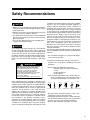
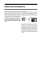
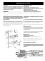
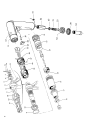
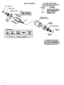
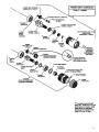
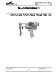
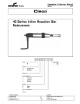
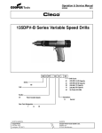
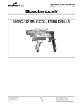
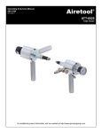
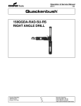
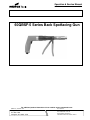
Operation & Service Manual
823237
07/03
60QBSF-5 Series Back Spotfacing Gun
For additional product information visit our website at www.coopertools.com
NORTH AMERICA
CooperTools
P.O. Box 1410
Lexington, SC 29071-1410
EUROPE
Recoules Operation
Zone Industrielle - B.P.28
Avenue Maurice Chevalier
77831 Ozoir-la-Ferriere Cedex, France
1
Safety Recommendations
For your safety and the safety of others, read and understand the safety recommendations and operating instructions before operating a drill.
Always wear protective equipment:
!
ventilation and/or wear a respirator. Respirators should be
selected, fitted, used and maintained in accordance with
Occupational Safety and Health Administration and other
applicable regulations. Read the material safety data
sheet of any cutting fluids or materials involved in the
drilling process.
WARNING
!
WARNING
Impact resistant eye protection
must be worn while operating
or working near this tool.
For additional information on eye protection and face
protection, refer to Federal OSHA Regulations, 29 Code
of Federal Regulations, Section 1910.133., Eye and Face
Protection, and American National Standards Institute,
ANSI Z87.1, Occupational and Educational Eye and Face
Protection. Z87.1 is available from the American National
Standards Institute, Inc., 11 West 42nd Street, New York,
NY 10036.
!
Do not wear loose fitting clothes,
long hair, gloves, ties or jewelry.
CAUTION
Personal hearing protection is
recommended when operating
or working near this tool.
Hearing protection is recommended in high noise areas
85 dBA or greater. The operation of other tools and
equipment in the area, reflective surfaces, process noises
and resonant structures can substantially contribute to,
and increase the noise level in the area. Excessive air
pressure above 90 PSIG or worn motor components can
also increase sound level emitted by tool. Proper hearing
conservation measures, including annual audiograms
and training in the use and fit of hearing protection devices
may be necessary. For additional information on hearing
protection, refer to Federal Regulations, Section 1910.95,
Occupational Noise Exposure, and American National
Standards Institute, ANSI S12.6, Hearing Protectors.
Cleco drills are designed to operate on 90 psig (6.2 bar)
maximum air pressure. If the tool is properly sized and
applied, higher air pressure is unnecessary. Excessive air
pressure increases the loads and stresses on the tool
parts and may result in breakage. Installation of a filterregulator-lubricator in the air supply line ahead of the tool
is recommended.
Before the tool is connected to the air supply, check the
throttle for proper operation (i. e., throttle moves freely and
returns to closed position). Being careful not to endanger
adjacent personnel, clear the air hose of accumulated
dust and moisture. Before removing a tool from service or
changing a drill bit, tap, reamer, or any accessory make
sure the air line is shut off and drained of air. This will
prevent the tool from operating if the throttle is accidently
engaged.
Sudden and high reaction torque may
be experienced with any drill if:
• drill motor stalls by excessive load being applied to drill
bit or drill bit snags on material being drilled.
• on break-through when the drill bit passes through the
material being drilled. User must be prepared to resist
torque.
!
!
WARNING
Wear respirator where
necessary.
Drilling operations may produce hazardous fumes and/or
dust. To avoid adverse health effects utilize adequate
2
Follow good machine shop practices.
Rotating shafts and
moving components
can entangle and entrap, and can result
in serious injuries.
Never wear long hair,
loose-fitting clothes,
gloves, ties, or jewelry when working
with or near a drill of
any type.
CAUTION
Safety Recommendations
!
CAUTION
• Drill bits are sharp. Handle them carefully to avoid injury.
• Cutting tool maximum speed rating must equal or exceed
rated speed of tool.
• Drill bits or accessories not centered properly in the chuck
can cause excessive wobble or vibration.
• Use appropriately sized chuck key to securely tighten drill
bit, tap, or reamer in drill chuck. Always remove chuck key
before starting tool.
• Use care when drilling because of the possibility of the
cutting tool bending or breaking.
!
CAUTION
Tools equipped with chuck capacity over 1/4" should have
at least one handle offset at a right angle to drill axis to
counteract torque developed by tool. If tool is equipped with
a chuck over 3/8" capacity, two handles at right angles to
the drill axis should be used. One handle should contain the
tool throttle, such as pistol grip or offset handle models.
Always use a dead handle with low RPM — high torque
tools.
!
WARNING
Repetitive work motions and/or vibration
may cause injury to hands and arms.
Use minimum hand grip force consistent
with proper control and safe operation.
Keep body and hands warm and dry.
Avoid anything that inhibits blood circulation.
Avoid continuous vibration exposure.
Keep wrists straight.
Avoid repeated bending of wrists and hands.
Some individuals may be susceptible to disorders of the
hands and arms when performing tasks consisting of highly
repetitive motions and/or exposure to extended vibration.
Cumulative trauma disorders such as carpal tunnel syndrome and tendonitis can be caused or aggravated by
repetitious, forceful exertions of the hands and arms.
Vibration may contribute to a condition called Raynaud's
Syndrome. These disorders develop gradually over periods of weeks, months, and years. It is presently unknown
to what extent exposure to vibrations or repetitive motions
may contribute to the disorders. Hereditary factors,
vasculatory or circulatory problems, exposure to cold and
dampness, diet, smoking and work practices are thought to
contribute to the conditions. Any tool operator should be
aware of the following warning signs and symptoms so that
a problem can be addressed before it becomes a debilitating injury. Any user suffering prolonged symptoms of
tingling, numbness, blanching of fingers, clumsiness or
weakened grip, nocturnal pain in the hand, or any other
disorder of the shoulders, arms, wrists, or fingers is advised
to consult a physician. If it is determined that the symptoms
are job related or aggravated by movements and postures
dictated by the job design, it may be necessary for the
employer to take steps to prevent further occurrences.
These steps might include, but are not limited to, repositioning the workpiece or redesigning the workstation, reassigning workers to other jobs, rotating jobs, changing work
pace, and/or changing the type of tool used so as to
minimize stress on the operator. Some tasks may require
more than one type of tool to obtain the optimum operator/
tool/task relationship.
The following suggestions will help reduce or moderate the
effects of repetitive work motions and/or extended vibration
exposure:
• Use a minimum hand grip force consistent with proper
control and safe operation
• Keep body and hands warm and dry (cold weather is
reported to be a major factor contributing to Raynaud's
Syndrome)
• Avoid anything that inhibits blood circulation
—Smoking Tobacco (another contributing
factor)
—Cold Temperatures
—Certain Drugs
• Tasks should be performed in such a manner that the
wrists are maintained in a neutral position, which is
not flexed, hyperextended, or turned side to side.
Avoid
Extension
OK
Neutral
Avoid
Flexion
Avoid
Radial Deviation
OK
Avoid
Neutral
Ulnar Deviation
• Stressful postures should be avoided — select a tool
appropriate for the job and work location
• Avoid highly repetitive movements of hands and wrists,
and continuous vibration exposure (after each period of
operation, exercise to increase blood circulation)
• Keep tool well maintained and replace worn parts
3
Safety Recommendations
WARNING
!
OVER
Repetitive work motions and/or vibration
can cause injury to hands and arms.
Use minimum hand grip force consistent with
proper control and safe operation.
Keep body and hands warm and dry.
Avoid anything that inhibits blood circulation.
Avoid continuous vibration exposure.
Keep wrists straight.
Avoid repeated bending of wrists and hands.
CAUTION
!
Personal hearing protection is
recommended when operating
or working near this tool.
WARNING
Hearing protection is recommended in high noise
areas (above 85 dBA). Close proximity of other
tools, reflective surfaces, process noises, and
resonant structures can substantially contribute
to the sound level experienced by the user.
203185
!
203185
Impact resistant eye protection
must be worn while operating
or working near this tool.
READ
OPERATING
INSTRUCTIONS
Read Operating Instructions carefully. Follow
the Safety Recommendations for your safety
and the safety of others.
Warning Labels
The warning labels found on these tools are an essential
part of this product. Labels should not be removed. Labels
should be checked periodically for legibility. Replace warning labels when missing or when the information can no
longer be read. Replacement labels can be ordered as any
spare part.
Do not remove this tag until
the operator of this tool has
read these safety precautions.
Work gloves with vibration reducing liners and wrist supports are available from some manufacturers of industrial
work gloves. Tool wraps and grips are also available from
a number of different manufacturers. These gloves, wraps,
and wrist supports are designed to reduce and moderate
the effects of extended vibration exposure and repetitive
wrist trauma. Since they vary widely in design, material,
thickness, vibration reduction, and wrist support qualities,
it is recommended that the glove, tool wrap, or wrist support
manufacturer be consulted for items designed for your
specific application. WARNING! Proper fit of gloves is
important. Improperly fitted gloves may restrict blood
flow to the fingers and can substantially reduce grip
strength.
203287
This information is a compilation of general safety practices
obtained from various sources available at the date of
production. However, our company does not represent
that every acceptable safety practice is offered herein, or
that abnormal or unusual circumstances may not warrant
or require additional procedures. Your work may require
additional specific safety procedures. Follow these procedures as required by your company. For more information,
see the latest edition of ANSI B186.1, Safety Code for
Portable Air Tools, available from the American National
Standards Institute, Inc., 11 West 42nd Street, New York,
NY 10036.
4
OPERATING INSTRUCTIONS
OPERATION
The 60QBSF-5 series drills are designed to operate on 90
PSIG (6.2 bar) air pressure. The 60QBSF-5 series requires a
5/16" hose. The drill is started by depressing the trigger and is
stopped by releasing the trigger.
LUBRICATION
An automatic in-line filter-lubricator is recommended as it
increases tool life and keeps the tool in sustained operation.
The in-line lubricator should be regularly checked and filled
with a good grade of 10W machine oil. Proper adjustment of
the in-line lubricator is performed by placing a sheet of paper
next to the exhaust ports and holding the throttle open approximately 30 seconds. The lubricator is properly set when a light
stain of oil collects on the paper. Excessive amounts of oil
should be avoided.
In the event that it becomes necessary to store the tool for an
extended period of time (overnight, weekend, etc.), it should
receive a generous amount of lubrication at that time and again
when returned to service. The tool should be stored in a clean
and dry environment.
OPERATING PRINCIPLE
Cycle sequence
Connect the tool to the compressed air supply.
Remove the nose (26). Unscrew the clamping nut (25). Insert
the pilot into the spindle (10).
Position the pilot into an appropriate collet.
Tighten the clamp nut (25) and replace the nose (26).
1. Insert the pilot into the pre-drilled hole on the part.
Place the spotfacer at the end of the pilot.
2. Make sure that the depth is correctly set (refer to the
“Machine Settings”). Place the mounting base (27) is in contact
with the part.
3. Press the trigger of the drill (29) to set the spindle in motion.
4. Press the moble lever (13) for carrying out the spotfacing.
Release the moble lever (13) and then the trigger.
5. Remove the spotfacer and repeat the sequence for the next
part.
Mechanical Principle
The back spotfacing unit is made up of a pneumatic motor
which enables the spindle (10) to be set in motion by means of
a spindle driver (18).
The spindle advance is controlled by the physical effort of the
operator who manipulates the moble lever (13).
Machine Setting
Setting the spotfacing depth
Turn off the tool.
Unscrew the locking nut (20) for releasing the setting.
Pull the vernier assembly (22) towards the lock nut (20).
While maintaining the vernier assembly pulled out, turn the
adjustment nut (23) to the desired value.
Each scale division is equal to 0.001‘’.
After setting the spotfacing depth, release the vernier assembly
(22) and tighten the lock nut (20) so that it touches the vernier
assembly.
Stroke
Depth
of
Spotfacing
5
6
INDEX NO.
PART NO.
1
2
3
4
5
6
7
8
9
10
11
12
13
14
15
16
17
18
19
20
21
22
23
24
25
26
27
28
29*
30*
31*
32*
33*
34*
35*
36*
38*
39*
40
42
641356
91013010
93430085
90420025
91825060
90620020
94221135
90510035
90205360
90030025
93440000
93060020
93060025
91216235
90280045
90245100
90280040
91013005
90010120
90495020
93430020
94215020
90285005
91825065
90810030
90820010
90835045
90825005
1110038
1110077
1012024
1110052
01-2518
1110079
1006577
1110134
1110892
1110053
632705
202020
DESCRIPTION
Motor assembly
Driver
Spring
Housing
Ceclips
Retainer
Screw M4 x 5
Spindle housing
Bushing
Spindle
Washer
Fixed lever
Mobile Lever
Pin dia. 5 x 12
Ball thrust bearing
Ball 2mm dia.
Ball thrust bearing
Spindle driver
Needle dia. 2.5 x 17.8
Nut
Spring
Vernier Assembly
Slotted base
Lock ring
Nut
Nose
Mounting base
Nose piece
Trigger
Push rod
Retainer ring
Valve housing
Tip valve
Spring
Screen
Muffler
Muffler diffuser
Hose adapter 1/4 NPT
Name plate
Name plate drive screw
(not shown)
QUANITY
1
1
1
1
1
1
3
1
2
1
1
1
1
1
1
17
1
1
1
1
1
1
1
1
1
1
1
1
1
1
1
1
1
1
1
2
1
1
1
2
70100400 is the front subassembly.
* Parts included in handle subassembly 1025562
Motor adapter is included in motor assembly 641356
Motor & Gear Train parts on pages 8 & 9.
7
8
9
NOTES
10
NOTES
11
CooperTools
P.O. Box 1410
Lexington, SC 29071-1410
USA
Phone: 803-359-1200
Fax: 803-808-6735
www.coopertools.com
12
Recoules, S.A.
Zone industrielle - B.P. 28
CooperTools Cedex
77831 Ozoir-la-Ferrière
7007 Pinemont
France
Houston, Texas 77040
Téléphone:Phone:
(33) 01
64 43 22 00
(713) 462-4521
Téléfax: Fax:
(33)
01
64 40 17 17
(713) 460-7008
www.cooperindustries.com