1
Installation and Operation Instructions for the following model:
SNCA-HRX550/EXT, SNCA-HRX550/INT,
& SNCA-HRX550EXT/W
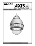
Outdoor and Indoor Dome Housings
SNCA-HRX550/EXT
Outdoor Pendant Housing with heater & blower, clear lower dome
SNCA-HRX550/INT
Indoor Pendant Housing with heater & blower, tinted lower dome
SNCA-HRX550EXT/W Outdoor Pendant Housing with heater & blower, clear lower dome,
and a wireless antenna cable
Note: AC 24V power supply for the camera and the heater/blower is an installer/re-seller provided item. Please refer to Electrical Specifications for power consumption details. Indoor models do not have heater/blower or pre-run cables.
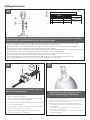
Note: Please note that to achieve the increased depth with the aspheric design for optimal camera lens to capsule orientation, the capsule is slightly angled around the highest
section. This creates a ”line’, visible to the naked eye, around the upper most section of the capsule. This “line” serves as the geometric center line used to insure proper
camera placement. It is not typically seen by the camera. However, Sony RZ series PTZ cameras are able to tilt up above the horizon to 25°, this wide range of tilt motion at
a wide angle view may cause this line to be captured in the image.
Mounting instructions for:
SNC-RZ25
SNC-RX530, 550, 570
SNC-RS44, 46
SNC-RH124
SNC-EP580, 550, 520
SNC-ER580, 550, 520
81-IN6605 12202011
IMPORTANT SAFEGUARDS
1 Read instructions - All the safety and operating
instructions should be read before the unit is
operated.
2 Retain instructions - The safety and operating
instructions should be retained for furture reference.
3 Heed Warnings - All warnings on the unit and in the
operating instructions should be adhered to.
4 Follow instructions - All operating and user instructions
should be followed.
5 Ellectrical Connections - Only a qualified electrician
should make electrical connections.
6 Attachments - Do not use attachments not
recommended by the product manufacturer as they
may cause hazards.
7 Cable Runs- All cable runs must be within permissible
distance.
8 Mounting - This unit must be properly and securely
mounted to a supporting structure capable of
sustaining the weight of the unit.
Accordingly:
a. The installation should be made by a qualified
installer.
b. The installation should be in compliance with local
codes.
c. Care should be exercised to select suitable
hardware to install the unit, taking into account
both the composition of the mounting surface and
the weight of the unit.
Be sure to periodically examine the unit and the supporting
structure to make sure that the integrity of the installation is
intact. Failure to comply with the foregoing could result in
the unit separating from the support structure and falling,
with resultant damages or injury to anyone or anything
struck by the falling unit.
UNPACKING
Unpack carefully. Electronic components can be
damaged if improperly handled or dropped. If an item
appears to have been damaged in shipment, replace
it properly in its carton and notify the shipper.
Be sure to save:
1 The shipping carton and packaging material.
They are the safest material in which to make
future shipments of the equipment.
2 These Installation and Operating Instructions.
CAUTION
RISK OF ELECTRIC SHOCK
DO NOT OPEN
CAUTION: TO REDUCE THE RISK OF
ELECTRIC SHOCK, DO NOT REMOVE
COVER ( OR BACK). NO USER- SERVICEABLE PARTS INSIDE. REFER SEVICING TO
QUALIFIED SERVICE PERSONNEL.
The lightning flash with an arrowhead
symbol, within an equilateral triangle, is
intended to alert the user to the presence
of non-insulated “dangerous voltage”
within the product’s enclosure that may be
of sufficient magnitude to constitute a risk
to persons.
Este símbolo se piensa para alertar al usuario a la
presencia del “voltaje peligroso no-aisIado” dentro del
recinto de los productos que puede ser un riesgo de
choque eléctrico.
Ce symbole est prévu pour alerter I’utilisateur à la
presence “de la tension dangereuse” non-isolée dans la
clôture de produits qui peut être un risque de choc
électrique.
Dieses Symbol soll den Benutzer zum Vorhandensein der
nicht-lsolier “Gefährdungsspannung” innerhalb der
Produkteinschließung alarmieren die eine Gefahr des
elektrischen Schlages sein kann.
Este símbolo é pretendido alertar o usuário à presença
“di tensão perigosa non-isolada” dentro do cerco dos
produtos que pode ser um risco de choque elétrico.
Questo simbolo è inteso per avvertire I’utente alla
presenza “di tensione pericolosa” non-isolata all’interno
della recinzione dei prodotti che può essere un rischio di
scossa elettrica.
The exclamation point within an equilateral
triangle is intended to alert the user to
presence of important operating and
maintenance (servicing) instructions in the
literature accompanying the appliance.
Este símbolo del punto del exclamation se piensa para
alertar al usuario a la presencia de instrucciones
importantes en la literatura que acompaña la
aplicación.
Ce symbole de point d’exclamation est prévu pour
alerter l’utilisateur à la presence des instructions
importantes dans la littérature accompagnant
l’appareil.
Dieses Ausruf Punktsymbol soll den Benutzer zum
Vorhandensein de wichtigen Anweisungen in der
Literatur alarmieren, die das Gerät begleitet.
Este símbolo do ponto do exclamation é pretendido
alertar o usuário à presença de instruções importantes
na literatura que acompanha o dispositivo.
SERVICE
If technical support or service is needed, contact
Sony at the following number:
TECHNICAL SUPPORT
8:15 AM to 7:30 PM
(Eastern Time)
1 - 800 - 883 - 6817
©2007 Sony Corporation
SAFETY PRECAUTIONS
Questo simbolo del punto del exclamaton è inteso per
avvertire l’utente alla presenza delle istruzioni importanti
nella letteratura che accompagna l'apparecchio.
Manufactured exclusively for Sony Electronics by:
Videolarm, Inc
2525 Park Central
Decatur, GA 30035
Contents of Box
Contents of Box Details
A
(1) Spacer Packet
(4) ½”
(8)
25mm
(4)
2”
200mm
1”
50mm
(4) M3 x 6mm Machine Screw
(4) M3 lock washers
(1) 1/4 x 20 Bolt
(1) 1/4 flat washer
(1) 1/4 lock washer
(3) 8 x 32 x 3/8" bolt
C
(3) Cable ties
B
B
(1) 4 Pin Power Connector
(1) RJ45 Coupling
D
*
C
(1) Teflon Tape
A
(1) Pendant Gasket
D
*
*
(1) WiFi Bracket
(1) 5/16 x 18 U-Bolt
(2) 5/16 x 18 Nut
(2) Cable Tie
* Wireless units only
Electrical Specifications
Power 24VAC, Class 2 Only
(OUTDOOR ONLY):
SNCA-HRX550/EXT
SNCA-HRX550EXT/W
SNCA-HRX550/EXT
SNCA-HRX550EXT/W
SNCA-HRX550/INT
1
SNCA-HRX550/INT
UNINL7C2 &
UNINL7T2
26 Watts at 24 VAC (Heater and Blower)
25 Watts at 24 VAC (Camera)
(INDOOR ONLY):
SNCA-HRX550/INT
See Camera Specifications.
Tools Required: .100" Flat Head Screwdriver
Phillips Head Screwdriver
(ONLY AL AIRE LIBRE):
SNCA-HRX550/EXT, SNCA-HRX550EXT/W
26 vatios en 24VAC (calentador y soplador)
25 vatios en 24VAC (cámara fotográfica)
(ONLY DE INTERIOR):
There are no pre-run cables on the indoor
models. (Proceed to Camera Installation section)
SNCA-HRX550/INT
• Hay ningún pre-funciona los cables en los modelos de interior.
(Continúe con la sección de instalación de la cámara)
Herramientas Requeridas: Destornillador PrincipalPhillips
• Il y a aucun pré-courent des câbles sur les modèles d'intérieur.
Vea Las Especificaciones De la Cámara fotográfica.
Del Destornillador Principal Plano Del 100"
(ONLY EXTÉRIEURS):
SNCA-HRX550/EXT, SNCA-HRX550EXT/W
26 watts à 24VAC (réchauffeur et ventilateur)
25 watts à 24VAC (appareil-photo)
(ONLY D'INTÉRIEUR):
SNCA-HRX550/INT
(Passez à la section Installation de caméra)
• Es gibt kein vor-laufen lassen Kabel auf den Innenmodellen.
(Fahren Sie mit Kamera Installations-Abschnitt)
• Há nenhum pre-funciona cabos nos modelos indoor.
(Continue na seção Instalação da câmara)
• Ci è nessun pre-fa funzionare i cavi sui modelli dell'interno.
(Procedere alla sezione di installazione della fotocamera)
Voir Les Caractéristiques D'Appareil-photo.
Outils Requis: Tournevis Principal Phillips
De Tournevis Principal Plat De 100"
(IM FREIEN ONLY):
SNCA-HRX550/EXT, SNCA-HRX550EXT/W
26 Watt an 24VAC (Heizung und Gebläse)
25 Watt an 24VAC (Kamera)
2
Wire Gauge
5.5
(INNENONLY):
SNCA-HRX550/INT
10
Werkzeuge Erforderten: 100"Flacher HauptschraubenzieherKreuzkopfhauptschraubenzieher
30
Sehen Sie Kamera-Spezifikationen.
(ONLY AO AR LIVRE):
SNCA-HRX550/EXT, SNCA-HRX550EXT/W
20
40
50
26 watts em 24VAC (calefator e ventilador)
25 watts em 24VAC (câmera)
60
Veja Especificações Da Câmera.
80
(ONLY INDOOR):
SNCA-HRX550/INT
As Ferramentas Requereram: Chave de fenda Principal
Phillips Da Chave de fenda Principal Lisa Do 100"
(ONLY ESTERNI):
SNCA-HRX550/EXT, SNCA-HRX550EXT/W
26 watt a 24VAC (riscaldatore e ventilatore)
25 watt a 24VAC (macchina fotografica)
(ONLY DELL'INTERNO):
SNCA-HRX550/INT
Veda Le Specifiche Della Macchina fotografica
Attrezzi Richiesti: Cacciavite Capo "phillips" Del Cacciavite
Capo Piano Del 100"
,5
22
Total vA
consumed
70
ft
,75
20
1,0
18
1,5
16
2,5
14
400
m
120
600
960
121
182
292
180
300
480
800
4
12
6
10
-
-
2
MM
AWG
1300
36.5
54.9
91.4
146
243
396
86
141
225
358
571
905
1440
27.1
43.0
68.6
109
174
275
438
65
90
130
225
350
525
830
19.8
27.4
39.6
68.6
106
160
252
44
70
112
179
285
452
720
13.4
21.3
34.1
54.6
86.9
138
219
56
90
143
228
362
576
35
10.6
17.1
27.4
43.6
69.5
110
175
29
47
75
119
190
301
480
9.4
14.3
22.9
36.2
57.9
91.7
146
40
64
102
163
258
411
8.8
12.2
19.5
31.1
49.7
78.6
125
34
55
85
140
215
340
25
31
7.6
10.3
16.8
25.9
42.7
65.5
103
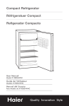
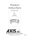
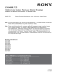
These are recommended maximum distances
for 24VAC with a 10% voltage drop.
• Éstos se recomiendan las distancias máximas para
24VAC con una caída de voltaje del 10%.
• Ceux-ci sont recommandés des distances maximum
pour 24VAC avec une chute de tension de 10%.
• Diese werden maximale Abstände für 24VAC mit
einem 10% Spannungsabfall empfohlen.
• Estes são recomendados distâncias máximas para
24VAC com uma queda de tensão de 10%.
• Questi sono suggeriti distanze massime per 24VAC con
una differenza de potenziale di 10%.
Camera Installation: SNC-RZ25
3
4
SNCRZ25
(2) 3mm screws
(1) ¼”x 20 bolt
lock washer
SNCRZ25
MOUNTING HOLES
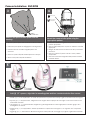
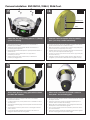
Remove the quick release plate from the
housing.
Mount the camera to the plate using the
appropriate pattern.
• Quite la placa rápida del lanzamiento de la cubierta.
• Monte la cámara fotográfica a la placa usando el
patrón apropiado.
• Montez l'appareil-photo au plat en utilisant le modèle
approprié.
• Bringen Sie die Kamera zur Platte mit dem passenden
Muster an.
• Monte a câmera à placa usando o teste padrão
apropriado.
• Monti la macchina fotografica alla piastra usando il
modello adatto.
• Enlevez le plat rapide de dégagement du logement.
• Entfernen Sie die schnelle Freigabeplatte vom
Gehäuse.
• Remova a placa rápida da liberação da carcaça.
• Rimuova la piastra rapida del rilascio
5
1/2” Spacers
or standoffs
Add (4) 1/2” spacers, align tabs in mounting plate and turn counterclockwise then secure.
• Añadir (4) 1 / 2 "de separación, se suman las pestañas en la placa de montaje y gire en sentido entonces seguro.
• Ajouter (4) 1 / 2 "d'espacement, l'alignement des onglets dans la plaque de montage et de tourner dans le sens
antihoraire sécurisée.
• "Hinzufügen" (4) 1 / 2 "Abstandhalter, Angleichung der Registerkarten in Montageplatte und dann gegen den
Uhrzeigersinn zu sichern.
• Adicionar (4) 1 / 2 "espaçadores, alinhar separadores na placa de montagem e, em seguida, vire à esquerda
segura.
• Aggiungi (4) 1 / 2 "Distanziatori, allineare le linguette nella piastra di montaggio e poi girate a garantire antiorario.
Camera Installation: SNC-RX530 / RX550 / RX570
6
SNCRX550
7
SNCRX550
(4) 3mm screws
SNC RX550
MOUNTING HOLES
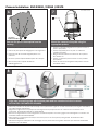
Remove the quick release plate from the
housing.
Mount the camera to the plate using the
appropriate pattern.
• Quite la placa rápida del lanzamiento de la cubierta.
• Monte la cámara fotográfica a la placa usando el
patrón apropiado.
• Montez l'appareil-photo au plat en utilisant le
modèle approprié.
• Bringen Sie die Kamera zur Platte mit dem passenden Muster an.
• Monte a câmera à placa usando o teste padrão
apropriado.
• Monti la macchina fotografica alla piastra usando
il modello adatto.
• Enlevez le plat rapide de dégagement du logement.
• Entfernen Sie die schnelle Freigabeplatte vom
Gehäuse.
• Remova a placa rápida da liberação da carcaça.
• Rimuova la piastra rapida del rilascio
dall'alloggiamento.
8
Align tabs in mounting plate with the base plate and turn counterclockwise to secure.
NO SPACERS OR STANDOFFS REQUIRED.
• Alinee las pestañas en la placa de montaje con la placa base y girar en sentido antihorario para seguro. SPACERS O
NO OBLIGATORIO STANDOFFS.
• Alignez les onglets dans une plaque de montage avec la plaque de base et à assurer son tour dans le sens
antihoraire. SPACERS STANDOFFS OU NON REQUIS.
• Richten Sie Registerkarten in Montageplatte mit der Bodenplatte und dann gegen den Uhrzeigersinn zu sichern. NO
SPACERS ODER Standoffs REQUIRED.
• Alinhar guias na montagem da chapa com base prato e vire à esquerda para garantir. SPACERS OU NÃO
STANDOFFS REQUIRED.
• Allineare le linguette nella piastra di montaggio con la piastra di base e girare antiorario per sicurezza. DISTANZIALI
STANDOFFS N O RICHIESTE.
Camera Installation: SNC-RZ25 & SNC-RX SERIES in Wireless Ready Housing
SNC-RZ25
9
(2) 3mm screws
(1) ¼”x 20 bolt
lock washer
MOUNTING
PATTERN
1/2” Spacers
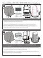
Remove the quick release plate and mount it to the camera using the correct pattern, then add (4) 1/2” spacers, align
tabs on the mounting plate and turn counterclockwise to secure.
• Retire la placa y rápido montaje para la cámara utilizando el patrón, y luego añadir (4) 1 / 2 "de separación, se suman las pestañas
sobre la placa de montaje y gire en sentido antihorario para seguro.
• Retirez le plateau rapide et de le monter sur l'appareil en utilisant le modèle, puis ajouter (4) 1 / 2 "d'espacement, l'alignement des
onglets sur la plaque de montage et de tourner dans le sens antihoraire à garantir.
• Entfernen Sie die Schnellwechselplatte und montieren Sie ihn an der Kamera mit dem richtigen Muster, dann (4) 1 / 2 "
Zwischenstücken, Angleichung der Registerkarten auf der Montageplatte und dann gegen den Uhrzeigersinn zu sichern.
• Remova a placa liberação rápida e montá-lo para a câmera usando o padrão correto, em seguida acrescentar (4) 1 / 2 "
espaçadores, alinhar guias sobre a placa de montagem e vire à esquerda para garantir.
• Rimuovere la piastra a sgancio rapido e montare per la fotocamera utilizzando il modello corretto, quindi aggiungere (4) 1 / 2 "
distanziali, allineare le linguette sulla piastra di montaggio e girare antiorario per sicurezza.
10
SNC-RX SERIES
(4) 3mm screws
MOUNTING
PATTERN
Remove the quick release plate and mount it to the camera using the correct pattern. Align
tabs on the mounting plate with the base plate screws and turn counterclockwise to secure.
NO SPACERS REQUIRED.
• Quite la placa rápida del lanzamiento y móntela a la cámara fotográfica usando el patrón correcto. Alinee las lengüetas en la placa de
montaje con los tornillos del embase y dé vuelta a la izquierda para asegurar.
• Enlevez le plat rapide de dégagement et montez-l'à l'appareil-photo en utilisant le modèle correct. Alignez les étiquettes du plat de support
avec les vis d'embase et tournez dans le sens contraire des aiguilles d'une montre pour fixer.
• Entfernen Sie die schnelle Freigabeplatte und bringen Sie sie zur Kamera mit dem korrekten Muster an. Richten Sie Vorsprünge auf der
Montageplatte mit den Grundplatteschrauben aus und drehen Sie nach links, um zu sichern.
• Remova a placa rápida da liberação e monte-a à câmera usando o teste padrão correto. Alinhe abas na placa de montagem com os
parafusos da placa baixa e gire-as no sentido anti-horário para fixar-se.
• Rimuova la piastra rapida del rilascio e montila alla macchina fotografica usando il modello corretto. Allinei le linguette sul giunto di supporto
con le viti della base di appoggio e giri in senso antiorario per fissare.
Camera Installation: SNC-RH124 / RS44 / RS46
11
SNC-RH124
SNC-RS44
SNC-RS46
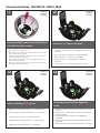
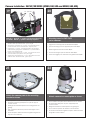
Remove existing bracket to mount SNC-RH124
or the SNC-RS series cameras.
• Retire el soporte existentes para organizar SNC-RH124 o la
SNC-cámaras de la serie RS.
• Retirez le support afin de faire face SNC-RH124 ou le Groupe
SNC-caméras de la série RS.
• Entfernen Sie vorhandene Halterung an SNC-mount-RH124
oder die SNC-RS-Serie Kameras.
• Remover suporte existente para montar SNC-RH124 ou do
SNC câmeras da série RS.
• Rimuovere supporto esistente per montare SNC-RH124 o la
SNC-telecamere della serie RS.
13
SNC-RH124
SNC-RS44
SNC-RS46
Add four additional 1/2” spacers.
• Agregue cuatro adicional de 1 / 2 "espaciadores.
• Ajoutez quatre supplémentaire de 1 / 2 "entretoises.
• Fügen Sie vier weitere 1 / 2 "Abstandshalter.
• Adicionar quatro adicional de 1 / 2 "espaçadores.
• Aggiungere quattro ulteriori 1 / 2 "distanziali.
12
SNC-RH124
SNC-RS44
SNC-RS46
Leave four 1/2” spacers as shown.
• Vacaciones de cuatro 1 / 2 "separadores como se
muestra.
• Laissez quatre 1 / 2 "espaceurs comme indiqué.
• Lassen Sie vier 1 / 2 "Spacer, wie gezeigt.
• Deixar quatro 1 / 2 "espaçadores, conforme
mostrado.
• Lascia quattro 1 / 2 "distanziali come mostrato.
14
SNC-RH124
SNC-RS44
SNC-RS46
Camera bracket should now appear as
shown.
• Soporte de cámara Shaud ahora aparecen como se
muestra.
• Support pour caméra devrait maintenant s'afficher
comme indiqué.
• Kamerahalterung shoud jetzt wie abgebildet
angezeigt.
• Suporte de câmera shoud agora aparecerá como
mostrado.
• Staffa Camera shoud ora appaiono come mostrato.
Camera Installation: SNC-RH124 / RS44 / RS46 Cont.
15
SNC-RH124
SNC-RS44
SNC-RS46
16
SNC-RH124
SNC-RS44
SNC-RS46
24VAC Power
RJ45
Attach the SNC RH124 ceiling plate to 1” (25mm)
spacers in housing.
Connect control and power wires to camera
base, (see Sony camera instructions).
• Ate la placa del techo de SNC RH124” a los espaciadores 1
(de 25m m) en la cubierta.
• Conecte el control y accione los alambres a la base de la cámara,
(véase las instrucciones de la cámara de Sony).
• Attachez le plat de plafond de SNC RH124 » aux entretoises 1
(de 25mm) dans le logement.
• Reliez la commande et actionnez les fils à la base d'appareil-photo,
(voir les instructions d'appareil-photo de Sony).
• Bringen Sie SNC RH124 Deckenplatte zu“ (25mm) Distanzscheiben 1
im Gehäuse an.
• Schließen Sie Steuerung an und treiben Sie Drähte zur Kameraunterseite an, (sehen Sie Sony-Kameraanweisungen).
• Una a placa do teto de SNC RH124” aos espaçadores 1
(de 25mm) na carcaça.
• Conecte o controle e pnha fios à base da câmera, (veja instruções
da câmera de Sony).
• Attacchi il piatto del soffitto di SNC RH124„ ai distanziatori 1
(di 25mm) in alloggiamento.
• Colleghi il controllo ed alimenti i legare alla base della macchina
fotografica, (vedi le istruzioni della macchina fotografica di Sony).
17
SNC-RH124
SNC-RS44
SNC-RS46
Attach base plate to ceiling plate with hardware
provided with camera.
18
SNC-RH124
SNC-RS44
SNC-RS46
Attach main connector and install camera to
base plate. Secure locking pins.
• El embase de la fijación a la placa del techo con hardware
proporcionó la cámara.
• Ate el conectador principal e instale la cámara al embase. Asegure
las clavijas de cierre.
• L'embase d'attache au plat de plafond avec le matériel a fourni en
appareil-photo.
• Attachez le connecteur principal et installez l'appareil-photo sur
l'embase. Fixez les chevilles de verrouillage.
• Grundplatte der Befestigungs zur Deckenplatte mit Hardware versah
mit Kamera.
• Bringen Sie Hauptverbindungsstück an und bringen Sie Kamera zur
Grundplatte an. Sichern Sie Sicherungsstifte.
• A placa baixa do anexo à placa do teto com ferragem forneceu
com a câmera.
• Una o conector principal e instale a câmera à placa baixa. Fixe os
pinos de travamento.
• La base di appoggio dell'attaccatura al piatto del soffitto con
fissaggi ha fornito la macchina fotografica.
• Attacchi il connettore principale ed installi la macchina fotografica
alla base di appoggio. Fissi i perni di bloccaggio.
Camera Installation: SNC-EP/ER SERIES (EP580, 550, 520 and ER580, 550, 520)
19
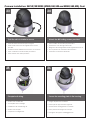
1½” spacers
20
½” spacers
Add (4) 1” and (4) ½“ spacers to the base bracket
as shown. NOTE: ½“ spacers already in place.
• Agregue (4) los espaciadores de 1” y (4) ½ “al soporte bajo como se
muestra. NOTA: espaciadores del ½ “ya en el lugar.
• Ajoutez (4) les entretoises de 1 » et (4) ½ « à la parenthèse basse
comme montrée. NOTE : entretoises de ½ « déjà en place.
• Fügen Sie (4) 1“ und (4) ½ „die Distanzscheiben dem niedrigen
Haltewinkel wie gezeigt hinzu. ANMERKUNG: ½ „Distanzscheiben
bereits an der richtigen Stelle.
• Adicione (4) espaçadores de 1” e (4) ½ “ao suporte baixo como
mostrado. NOTA: espaçadores do ½ “já no lugar.
• Aggiunga (4) i distanziatori del 1„ e (4) ½ “alla staffa bassa come
indicato. NOTA: distanziatori del ½ “già sul posto.
21
Attach the camera plate to the mounting
bracket as shown.
• Ate la placa de la cámara a la pletina como se muestra.
• Attachez le plat d'appareil-photo au plat de support
comme montré.
• Anbringen Sie die Kameraplatte zur Montageplatte wie
gezeigt.
• Una a placa da câmera à placa de montagem como
mostrada.
• Attacchi il piatto della macchina fotografica al giunto di
supporto come indicato.
Mounting holes for SNC-ER/EP
series cameras .
• Agujeros de montaje para las cámaras SNC-ER/EP.
• Trous de montage pour les appareils-photo SNC-ER/EP.
• Entlüftungslöcher für Kameras SNC-ER/EP.
• Furos de montagem para as câmeras SNC-ER/EP.
• Fori di montaggio per le macchine fotografiche SNC-ER/EP.
22
Attach camera to camera plate as shown.
• Ate la cámara a la placa de la cámara como se muestra.
• Attachez l'appareil-photo au plat d'appareil-photo
comme montré.
• Bringen Sie Kamera zur Kameraplatte wie gezeigt an.
• Una a câmera à placa da câmera como mostrada.
• Attacchi la macchina fotografica al piatto della macchina
fotografica come indicato.
Camera Installation: SNC-EP/ER SERIES (EP580, 550, 520 and ER580, 550, 520) Cont.
23
Twist the unit clockwise to secure.
24
Attach the M3 locking screws provided.
• Tuerza la unidad a la derecha para asegurar.
• Ate los tornillos de cierre M3 proporcionados.
• Tordez l'unité dans le sens des aiguilles d'une montre
pour fixer.
• Attachez les vis de blocage M3 fournies.
• Verdrehen Sie die Maßeinheit nach rechts, um zu sichern.
• Una os parafusos de travamento M3 fornecidos.
• Torça a unidade no sentido horário para fixar-se.
• Torca l'unità in senso orario per fissare.
25
Complete all wiring.
• Bringen Sie die bereitgestellten Sicherungsschrauben M3 an.
• Attacchi le viti di chiusura M3 fornite.
26
Secure the mounting plate in the housing.
• Termine todo el cableado.
• Asegure la pletina en la cubierta.
• Accomplissez tout le câblage.
• Fixez le plat de support dans le logement.
• Schließen Sie alle Verdrahtung ab.
• Sichern Sie die Montageplatte im Gehäuse.
• Termine toda a fiação.
• Fixe a placa de montagem na carcaça.
• Completi tutti i collegamenti.
• Fissi il giunto di supporto nell'alloggiamento.
Mounting Preparation
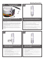
27
Connecting the Wireless
Card and Antenna
28
MMCX
For wireless models, after installing the wireless card
connect the antenna cable to the card. Please refer to
product manual for details.
•
•
•
•
•
Para los modelos sin hilos, después de instalar la tarjeta sin hilos conecte el
cable de la antena con la tarjeta. Refiera por favor al manual del producto
para los detalles.
Pour les modèles sans fil, après installation de la carte sans fil reliez le câble
d'antenne à la carte. Veuillez se référer au manuel de produit pour des détails.
Für drahtlose Modelle nachdem Sie die drahtlose Karte angebracht haben,
schließen Sie das Antenne Kabel an die Karte an. Beziehen Sie bitte sich
Produkthandbuch für Details.
Para modelos wireless, após ter instalado o cartão wireless conecte o cabo
da antena ao cartão. Consulte por favor ao manual do produto para
detalhes.
Per i modelli senza fili, dopo l'installazione della scheda senza fili colleghi il cavo
dell'antenna alla scheda. Riferiscasi prego al manuale del prodotto per i
particolari.
29
Securely attach pendant pipe or the UNI-WMB1. Pull
wiring through pipe and position grommet as shown.
• Segura adjuntar colgante o de la tubería de UNI-WMB1. Tire de la
tubería y el cableado a través de un drenaje timpánico posición como
se muestra.
• Securely joindre pendant la pipe ou le UNI-WMB1. Pull de câblage à
travers la pipe et la position œillet comme indiqué.
• Sicher befestigen Anhänger Rohr oder die UNI-WMB1. Ziehen Sie
Verkabelung durch Rohr-und Kabeldurchführungen Position wie
gezeigt.
• Securely anexar pingente cachimbo ou o UNI-WMB1. Puxar fiação
através do tubo e posição grommet como mostrado.
• Sospensione fissa tubo o la norma UNI-WMB1. Estrarre il tubo attraverso il
cablaggio e la posizione grommet come mostrato in figura.
30
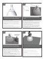
Wrap Teflon tape around the pipe threads
to ensure a tight seal.
Screw the coupling onto the pipe threads
until it is hand tight.
• La cinta del Teflon del abrigo alrededor de la pipa rosca
para asegurar un sello apretado.
• La bande de teflon d'enveloppe autour de la pipe filète
pour assurer un joint serré.
• Verpackung Teflonklebeband um das Rohr verlegt, um
eine feste Dichtung sicherzustellen.
• A fita adesiva do Teflon do envoltório em torno da
tubulação enfía para assegurar um selo apertado.
• Il nastro del Teflon dell'involucro intorno al tubo filetta per
accertare una guarnizione stretta.
• Atornille el acoplador sobre los hilos de rosca de la pipa
hasta que es mano firmemente.
• Vissez le couplage sur les fils de pipe jusqu'à ce que ce
soit main fortement.
• Schrauben Sie die Koppelung auf die Rohrgewinde, bis
es Hand fest ist.
• Parafuse o acoplamento nas linhas da tubulação até
que esteja mão firmemente.
• Avviti l'accoppiamento sui filetti del tubo fino a che non
sia fortemente mano.
TM
31
Screw the (2) bolts into the coupling.
• Atornille (2) los pernos en el acoplador.
• Vissez (2) les boulons dans l'accouplement.
• Schrauben Sie die (2) Schraubbolzen in die Koppelung.
• Parafuse (2) os parafusos no acoplamento.
32
Loop the lanyard over the set screw to
temporarily hold housing.
• Loop el cordón sobre el tornillo de fijación para mantener temporalmente de la vivienda.
• Boucle de la longe sur la vis de réglage pour détenir temporairement
des logements.
• Loop das Trageband über die Stellschraube, um vorübergehend halten
Gehäuse.
• Loop o colhedor sobre o parafuso para prender temporariamente
habitação.
• Loop il cordino sulla vite di tenere temporaneamente alloggi.
• Avviti (2) i bulloni nell'accoppiamento.
33
Make the appropriate wiring connections
from the dome to the pendant mount.
• Hacer las conexiones de cableado de la cúpula de la
pendiente de montaje.
• Faites le câblage de la coupole à la suspension de montage.
• Nehmen Sie die entsprechenden Kabel-Verbindungen von
der Kuppel auf dem Anhänger montiert.
• Faça as conexões de cabos da cúpula para o pingente
montagem.
• Apportare le opportune connessioni cablaggio dalla cupola
a montare il ciondolo.
34
Note: Install EP/ER Series cameras, before
installing the housing.
• Nota: Instale las cámaras de la serie de EP/ER, antes
instalación de la cubierta.
• Note : Installez les appareils-photo de série d'EP/ER, avant
installation du logement.
• Anmerkung: Bringen Sie EP/ER Reihenkameras, vorher an
Installierung des Gehäuses.
• Nota: Instale câmeras da série de EP/ER, antes instalando a
carcaça.
• Nota: Installi le macchine fotografiche di serie di EP/ER,
prima installazione dell'alloggiamento.
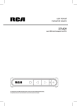
Wiring Instructions
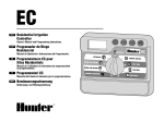
35
RJ45
24VAC
1
2
3
4
SNC-RZ30/SNC-RZ550
Camera
Camera
Heater/Blower
Red
Orange
Yellow
Heater/Blower
Green
18 Watts
25 Watts
26 Watts
1/0
Alarm 1
Alarm 2
Alarm 3
Common
1
2
3
4
Blue
Violet
Gray
White
RJ45
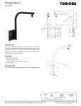
Make the appropriate male and female connections. Indoor model does not include pre-run cables.
Note: The video and alarm wires are not pre-run on these models.
• Haga las conexiones masculinas y femeninas apropiadas. El modelo de interior no incluye pre-funciona los cables.
Nota: Los alambres del vídeo y de la alarma no son pre-funcionan en estos modelos.
• Établissez les rapports masculins et femelles appropriés. Le modèle d'intérieur n'inclut pas pré-courent des câbles.
Note : Les fils de vidéo et d'alarme ne sont pas pré-courent sur ces modèles.
• Stellen Sie die passenden männlichen und weiblichen Beziehungen her. Innenmodell schließt nicht vor-laufen lassen Kabel ein.
Anmerkung: Die Video- und Warnungsdrähte sind nicht vor-laufen lassen auf diese Modelle.
• Faça as conexões masculinas e fêmeas apropriadas. O modelo indoor não inclui pre-funciona cabos.
Nota: Os fios do vídeo e do alarme não são pre-funcionam nestes modelos.
• Faccia i collegamenti maschii e femminili adatti. Il modello dell'interno non include pre-fa funzionare i cavi.
Nota: I legare dell'allarme e del video non sono pre-fanno funzionare su questi modelli.
36
Green
Jumpers
Wires from
Dome
Yellow
37
Mounting Preparation Continued
Orange
Red
Input
-
+
Add 2 jumpers if using a common power supply for
the camera, heater & blower.
• Añadir 2 jumpers si utiliza una fuente de alimentación para la
cámara, calefacción y ventilador.
• Ajoutez 2 cavaliers si vous utilisez une alimentation pour l'appareil
photo, appareil de chauffage et de soufflerie.
• Add 2 Jumper, wenn Sie eine gemeinsame Stromversorgung für die
Kamera, Heizung & Gebläse.
• Adicionar 2 jumpers comum se utilizar uma fonte de alimentação
para a câmara, aquecedor e ventilador.
• Aggiungere 2 ponticelli se si utilizza un alimentatore per la
fotocamera, riscaldamento e ventilatore.
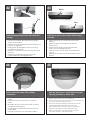
Undo the lanyard, pull housing up and twist
secure with the locking bolt and washers.
• Deshaga el acollador, tire de contener para arriba y tuerza seguro
con el perno y las arandelas de fijación.
• Défaites la lanière, tirez loger vers le haut et tordez bloqué avec le
boulon et les rondelles de fermeture.
• Annulieren Sie die Abzuglinie, ziehen Sie oben unterbringen und
verdrehen Sie sicheres mit dem verriegelnschraubbolzen und den
Unterlegscheiben.
• Undo o colhedor, puxe abrigar acima e torça seguro com o
parafuso e as arruelas travando.
• Undo la cordicella, tiri l'alloggio in su e torca sicuro con il bullone e
le rondelle di bloccaggio.
39
38
Slide the grommet down over the coupling to prevent
water from entering and complete the assembly.
• Resbale el ojal abajo sobre el acoplador para evitar que el agua
entre y para terminar a la asamblea.
• Glissez le canon isolant vers le bas au-dessus de l'accouplement
pour empêcher l'eau d'entrer et pour accomplir l'assemblée.
• Schieben Sie die Gummimuffe unten über der Koppelung, um zu
verhindern, daß Wasser und die Versammlung durchzuführen
hereinkommt.
• Deslize o ilhó para baixo sobre o acoplamento para impedir que a
água entre e para terminar o conjunto.
• Faccia scorrere il gommino di protezione giù sopra l'accoppiamento
per impedire l'acqua entrare e per completare il complessivo.
40
Wireless Systems Only
Wireless Systems Only
The 2’ cable provided is to be connected at the top of the
housing. Push down onto the connector and thread until it is
hand tight.
• El cable 2' proporcionado debe ser conectado en la tapa de la
cubierta. Empuje hacia abajo sobre el conectador y el hilo de
rosca hasta que es mano firmemente.
• Le câble 2'fourni doit être relié au dessus du logement. Abaissez sur
le connecteur et le fil jusqu'à ce que ce soit main fortement.
• Das bereitgestellte Kabel 2' soll an der Oberseite des Gehäuses
angeschlossen werden. Drücken Sie auf den Stecker und das
Gewinde runter, bis es Hand fest ist.
• O cabo 2' fornecido deve ser conectado no alto da carcaça.
Abaixe no conector e na linha até que esteja mão firmemente.
• Il cavo 2'fornito deve essere collegato alla parte superiore
dell'alloggiamento. Spinga sul connettore e sul filetto fino a che
non sia fortemente mano.
41
Wireless Systems Only
Antenna shown here
is the SNCA-AN1
Connect the other end of the cable to the antenna.
Follow the instructions on how to mount the antenna.
• Conecte el otro extremo del cable con la antena. Siga
las instrucciones en cómo montar la antena.
• Reliez l'autre extrémité du câble à l'antenne. Suivez les
instructions sur la façon dont monter l'antenne.
• Schließen Sie das andere Ende des Kabels an die
Antenne an. Befolgen Sie die Anweisungen in, wie man
die Antenne anbringt.
• Conecte a outra extremidade do cabo à antena. Siga
as instruções em como montar a antena.
• Colleghi l'altra estremità del cavo all'antenna. Segua le
istruzioni su come montare l'antenna.
Attach wireless bracket to Pendant pipe or wall mount.
•
Fije el soporte inalámbrico para Colgante tubería o montaje en
pared.
•
Joindre sans fil au support Pendentif pipe ou mural.
•
Befestigen Sie die Halterung Wireless Anhänger Rohr-oder
Wandmontage.
•
Anexar sem fios para suporte Pendant tubo ou parede montar.
•
Collegare wireless Staffa Ciondolo a tubo o il montaggio a parete.
43
42
Before
Tab
After
Loop the lanyard around the tab inside the
housing.
Align the arrows on the outside of the dome
and lock.
• Coloque el acollador alrededor de la lengüeta
dentro de la cubierta.
• Faites une boucle la lanière autour de l'étiquette à
l'intérieur du logement.
• Schlingen Sie die Abzuglinie um den Vorsprung
innerhalb des Gehäuses.
• Dê laços no colhedor em torno da aba dentro da
carcaça.
• Colleghi la cordicella in circuito intorno alla
linguetta all'interno dell'alloggiamento.
• Alinee las flechas en el exterior de la bóveda y
trábese.
• Alignez les flèches sur l'extérieur du dôme et
fermez à clef.
• Richten Sie die Pfeile auf der Außenseite der
Haube aus und verriegeln Sie sich.
• Alinhe as setas na parte externa da abóbada e
trave-as.
• Allinei le frecce sulla parte esterna della cupola e
blocchi.
44
45
Fasten down the dome with a Phillips
screwdriver.
• Sujete abajo de la bóveda con un destornillador
Phillips.
• Attachez en bas du dôme avec un tournevis
Phillips.
• Befestigen Sie sich hinunter die Haube mit einem
Kreuzkopfschraubenzieher.
• Prenda abaixo a abóbada com uma chave de
fenda Phillips.
• Fissisi giù la cupola con un cacciavite "phillips".
Wipe the dome clean. Please follow the proper
cleaning procedure as shown in 46.
• Limpie la cúpula limpio. Por favor, siga el procedimiento de
limpieza adecuado, como se muestra en 46.
• Essuyez le dôme propre. S'il vous plaît suivre la procédure de
nettoyage, comme indiqué dans le 46.
• Wischen Sie die Kuppel reinigen. Bitte beachten Sie die
ordnungsgemäße Reinigung Verfahren wie in 46.
• Limpe a cúpula limpo. Por favor, siga o procedimento
adequado de limpeza conforme indicado em 46.
• Pulire la cupola pulito. Si prega di seguire la corretta
procedura di pulizia, come indicato in 46.
46
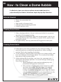
How - to Clean a Dome Bubble
To effectively clean your video surveillance dome bubble (acrylic or
polycarbonate) from debris, follow these simple step-by-step instructions.
Materials Needed
•
•
•
•
•
Clean, dry, pressurized air
Water
High quality soft paper towel
Isopropyl alcohol (rubbing alcohol)
Scratch-resistant cloth
Cleaning Dome Exterior
1. When cleaning exterior of dome, make sure bubble is connected
securely to the camera housing.
2. While utilizing a nonabrasive cloth and cleaning agent, safe for use
on acrylic or polycarbonate plastic, in a spiral motion, gently clean
exterior of bubble.
3. Dry immediately with dry, pressurized air to prevent water spots.
Cleaning Dome Interior
1. Safely remove the dome bubble from the camera housing. To
prevent scratches or additional imperfections, utilize a scratchresistant cloth when handling the bubble.
2. Once removed, carefully place the bubble on a clean surface, safe
from dust and any other foreign debris. Do not place the bubble
face down on its curved surface.
3. While holding onto the bubble, use clean, dry, pressurized air to
gently blow off all loose particles. For more thorough cleaning, try
one of the following:
i. Rinse bubble with water and immediately dry with
pressurized air to prevent water spots
ii. Roll a section of high-quality paper towel into a tube,
and tear tube in half. Wet torn edge with rubbing
alcohol solution (75% alcohol & 25% water). While
holding the bubble facing downward, wipe the interior
with the paper towel tube in a circular motion from the
outside – in. Use spiraling motions when cleaning.
Repeat above steps to clean entire bubble.
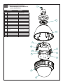
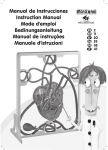
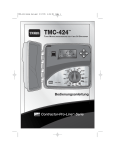
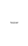
Replacement Parts List
8
SNCA-HRX550/EXT, SNCA-HRX550/INT,
& SNCA-HRX550EXT/W
Part Number
Description
1
RPFD060
CAMERA BRACKET
2
RPFD080
12 VDC BLOWER
3
RPRH707
CONNECTION PCB
4
RPFD702
24 VAC HEATER
5
RPFD709
HOUSING TOP
6A
RPFD7C
CLEAR REPLACEMENT DOME
6B
RPFD7T
TINTED REPLACEMENT DOME
7
RPFD7501
TRIM RING
8
SD0180W
PENDANT COUPLING (WHITE)
9
RPVL2636
ADAPTER RING
10
RPPKH3063
11
RPVL2825
RPVL3250
12
RPFD2612
HOUSING TOP - GASKET
N/S
RPPKH2220
HARDWARE PACKET
12
SPACER PACKET
MOUNTING PLATE (WIRELESS)
MOUNTING PLATE (NON-WIRELESS)
N/S
RPPKE1101
ELECTRICAL PACKET
N/S
RPPKH2240
WIRELESS BRACKET PACKET
5
3
4
2
10
1
9
11
7
6
LIMITED WARRANTY
FOR SONY SECURITY SYSTEMS PRODUCTS
SONY ELECTRONICS INC. ("Sony") warrants this Product to be free from defects in material or workmanship, as follows:
PRODUCT CATEGORY
Video Camera
MODEL PREFIXES
UNI-PC, UNI-PM
UniPak Series
PARTS
Three (3) Years except, a) camera
lens and b.) camera housing assembly
which are warranty for one (1) Year.
Video Camera
SSC, HVM,SPT
Color TV/Monitor
SSM
B/W Monitor
Time Lapse VCR/Recorder
SSM, FDM
EVT, SVT
Digital Video Recorder
HSR
HSRA
SVO
Camera Lenses: One (1) Year
All other parts: Three (3) Years
CRT: Two (2) Years
All other parts: Three (3) Years
All Parts: One (1) Year
Rotary Upper Drum Assembly:
Ninety (90) Days
All other parts (1) Year
All Parts: Two (2) Years
All Parts: Two (2) Years
Rotary Upper Drum Assembly:
Ninety (90) Days
All other parts: One (1) Year
VHS/S-VHS Recorder/Player
Duplication
(excluding
Products)
Hi8mm Recorder/Player
Video Printer
EVO
UP
Digital Video Printer
UP-D6300, D6400,
D6500
Accessories
Transmitter
YS, PGV
RSE, SNT
Thermal Head: Ninety (90) Days
All other parts: One (1) Year
Thermal Head: One (1) Year or
100,000 passes whichever occurs
Provided Sony approved
first.
premium media (such as Sony micro
printed PVC cards with SSD logo and
Sony UPR ribbons) are utilized.
All other parts: One (1) Year
All parts: One (1) Year
All parts: One (1) Year
LABOR
Three (3) Years except, a)
camera lens and b.) camera
housing assembly which are
warranty for one (1) Year.
Three (3) Years
Three (3) Years
One (1) Year
Ninety (90) Days
Two (2) Years
Two (2) Years
Ninety (90) Days
Ninety (90) Days
One (1) Year
One (1) Year
One (1) Year
During the labor warranty period, to repair the Product, Purchaser will either return the defective Product, freight prepaid, or deliver it
to a Sony Service Center or to a service facility authorized by Sony. The Product to be repaired is to be returned in either its original
carton or a similar package affording an equal degree of protection. Sony will return the repaired Product freight prepaid to
Purchaser. Sony is not obligated to provide Purchaser with a substitute unit during the warranty period or at any time. After the
applicable warranty period, Purchaser must pay all labor and/or parts charges.
The limited warranty stated on this card is subject to all of the following terms and conditions.
TERMS AND CONDITIONS
1. NOTIFICATION OF CLAIMS: WARRANTY SERVICE: If Purchaser believes that the Product is defective in material or
workmanship, then written notice with an explanation of the claim shall be given promptly by Purchaser to Sony but all claims for
warranty service must be made within the warranty period. If after investigation Sony determines that the reported problem was
not covered by the warranty, Purchaser shall pay Sony for the cost of investigating the problem at its then prevailing per
incident billable rate. No repair or replacement of any Product or part thereof shall extend the warranty period as to the entire
Product. The specific warranty on the repaired part only shall be in effect for a period of ninety
(90) days following the repair or replacement of that part or the remaining period of the Product parts warranty, whichever is greater.
2. EXCLUSIVE REMEDY: ACCEPTANCE: Purchaser's exclusive remedy and Sony's sole obligation is to supply (or pay for) all labor
necessary to repair any Product found to be defective within the warranty period and to supply, at no extra charge, new or rebuilt
replacements for defective parts. If repair or replacement fails to remedy the defect, then, and only in such event, shall Sony refund
to Purchaser the purchase price for such Product. Purchaser's failure to make a claim as provided in paragraph 1 above or continued
use of the Product shall constitute an unqualified acceptance of such Product and a waiver by Purchaser of all claims thereto.
3. EXCEPTIONS TO LIMITED WARRANTY: Sony shall have no liability or obligation to Purchaser with respect to any Product
requiring service during the warranty period which is subjected to any of the following: abuse, improper use: negligence, accid ent,
modification, failure of the end-user to follow the operating procedures outlined in the user's manual, failure of the end-user to follow
the maintenance procedures in the service manual for the Product where a schedule is specified for regular replacement or
maintenance or cleaning of certain parts (based on usage) and the end-user has failed to follow such schedule; attempted repair by
non-qualified personnel; operation of the Product outside of the published environmental and electrical parameters, or if such
Product's original identification (trademark, serial number) markings have been defaced, altered, or removed. Sony excludes from
warranty coverage Products sold AS IS and/or WITH ALL FAULTS and excludes used Products which have not been sold by Sony
to the Purchaser. Sony also excludes from warranty coverage Products located outside of the United States and Puerto Rico, and
consumable items such as fuses and batteries.
All software and accompanying documentation furnished with, or as part of the Product is furnished “AS IS” (i.e., without any
warranty of any kind), except where expressly provided otherwise in any documentation or license agreement furnished with the
Product.
LIMITED WARRANTY
FOR SONY SECURITY SYSTEMS PRODUCTS
4. PROOF OF PURCHASE: The Purchaser's dated bill of sale must be retained as evidence of the date of purchase and to establish
warranty eligibility.
DISCLAIMER OF WARRANTY
EXCEPT FOR THE FOREGOING WARRANTIES, SONY HEREBY DISCLAIMS AND EXCLUDES ALL OTHER WARRANTIES,
EXPRESS OR IMPLIED, INCLUDING, BUT NOT LIMITED TO ANY AND/OR ALL IMPLIED WARRANTIES OF
MERCHANTABILITY, FITNESS FOR A PARTICULAR PURPOSE AND/OR ANY WARRANTY WITH REGARD TO ANY CLAIM OF
INFRINGEMENT THAT MAY BE PROVIDED IN SECTION 2-312(3) OF THE UNIFORM COMMERCIAL CODE AND/OR IN ANY
OTHER COMPARABLE STATE STATUTE. SONY HEREBY DISCLAIMS ANY REPRESENTATIONS OR WARRANTY THAT THE
PRODUCT IS COMPATIBLE WITH ANY COMBINATION OF NON-SONY PRODUCTS PURCHASER MAY CHOOSE TO
CONNECT TO THE PRODUCT.
LIMITATION OF LIABILITY
THE LIABILITY OF SONY, IF ANY, AND PURCHASER'S SOLE AND EXCLUSIVE REMEDY FOR DAMAGES FOR ANY CLAIM OF
ANY KIND WHATSOEVER, REGARDLESS OF THE LEGAL THEORY AND WHETHER ARISING IN TORT OR CONTRACT,
SHALL NOT BE GREATER THAN THE ACTUAL PURCHASE PRICE OF THE PRODUCT WITH RESPECT TO WHICH SUCH
CLAIM IS MADE. IN NO EVENT SHALL SONY BE LIABLE TO PURCHASER FOR ANY SPECIAL, INDIRECT, INCIDENTAL, OR
CONSEQUENTIAL DAMAGES OF ANY KIND INCLUDING, BUT NOT LIMITED TO, COMPENSATION, REIMBURSEMENT OR
DAMAGES ON ACCOUNT OF THE LOSS OF PRESENT OR PROSPECTIVE PROFITS OR FOR ANY OTHER REASON
WHATSOEVER.
____________________________________________________________________________________________________
For further information and the name of the nearest authorized Sony service facility contact:
SONY Security Products Service
16795 VIA Del Campo
Bldg 3, Dock 32
ATTN: Security Products
San Diego, California 92127
Voice: 800-472-7669
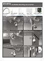
Available Mounting Accessories
SNCA-WM20FC
Gooseneck
Wall Mount
SNCA-WM30G
Aluminum
Parapet Mount
SNCA-PM3
Aluminum Existing
Pole Mount Adaptor
SNCA-WM20FC Wall Mount
Mounting Accessories Needed:
SNCA-CA2
Aluminum Corner
Mount Adaptor
• UNI-WMB1 - Gooseneck
Wall Mount
• UNI-PMA1 - Aluminum
Exising Pole Mount
Adaptor
• Outdoor Pendant
Housing
SNCA-WM30G
SNCA-CA2 Corner Mount
RoofMount (Parapet)
SNCA-POWER BOX Power Block Unit (Wall Mount)
175 / 220 Vac to 24Vac
Mounting Accessories Needed:
UNI-WMBI - Gooseneck Wall Mount
Power Block Unit
SNCA-PM3 Pole Mount
Mounting Accessories Needed:
UNI-WMB1 - Gooseneck Wall Mount
Outdoor Pendant Housing
SNCA-WM30G - Aluminum Parapet Mount
Outdoor Pendant Housing
SNCA-POWER BOX
Mounting Accessories Needed:
• UNI-CMA1 - Aluminum Corner
Mount Adaptor
• UNI-WMB1 - Gooseneck Wall
Mount
• Outdoor Pendant Housing
SNCA-POWER BOX Power Block Unit (Pole Mount)
Mounting Accessories Needed:
• UNI-WMB1 Gooseneck Wall
Mount