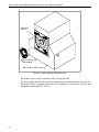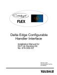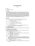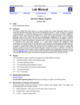
1
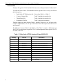
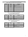
Delta Castle LX7500 Handler Interface for AMD Using Delta Seal Adapter Installation Manual Revision 0120 Documentation Part No. 573-004-00 LIMITED REPRODUCTION RIGHTS This document may be reproduced by a Teradyne Customer solely for internal use with authorized systems by operators who have agreed to observe this restriction. Any copy of this document, or portions thereof, must contain the copyright and proprietary rights notice as stated on the original. Copyright 2001 Teradyne, Inc. Printed in the U.S.A. The material in this document is subject to change without notice. Teradyne, Inc. assumes no responsibility for any errors which may appear in this document. RESTRICTED RIGHTS LEGEND Use, duplication, or disclosure by the Government is subject to restrictions as set forth in subdivision (b) (3) (ii) of the Rights in Technical Data and Computer Software clause of DFARS 52.227-7013. Teradyne, Inc. 321 Harrison Avenue Boston, MA 02118 About this Manual Delta Castle LX7500 Handler Interface for AMD Using Delta Seal Adapter This manual provides installation instructions for the Delta Castle LX7500 material handler interface. The material in this manual is being provided for informational purposes and is subject to change without notice. Additional Information Further information about the Catalyst Test System can be found in the following Teradyne service manuals: • Catalyst Test Head Service Manual pn 553-700-58 • Catalyst Site Preparation Guide pn 553-700-60 • Catalyst Service Manual pn 553-700-63 • Catalyst KCS and Manipulator Manual pn 553-700-78 Revision History Manual Name: Delta Castle LX7500 Handler Interface for AMD using Delta Seal Adapter Part Number: 573-004-00 ___________________________________________________________________________ Revision Date Reason for Change 0120 Initial Release Delta Castle LX7500 Handler Interface Manual for the Catalyst Test System Table of Contents Overview....................................................................................................................1 Installation Steps .......................................................................................................1 Unpacking the Interface Assembly Kit.......................................................................1 Assemblies ................................................................................................................2 Site Preparation.........................................................................................................5 Mounting Plate Modification ......................................................................................7 Installation .................................................................................................................9 Delta Castle LX7500 Handler Interface Manual for AMD Overview This manual describes the assembly and installation of a Delta Castle LX7500 material handler interface to the Catalyst Test System. This interface is for use with a 0.187" thick handler interface board (HIB). Installation Steps 1) Unpacking the Interface Assembly Kit 2) Site Preparation 3) Mounting Plate Modification 4) Installation Unpacking the Interface Assembly Kit Unpack and inspect the interface assembly kit thoroughly for shipping damage. Verify the material against the packing list to make sure that all necessary components are included in the kit. If there is damage or if there are any discrepancies, report it immediately to your local Teradyne field service office before proceeding with the installation. 1 Delta Castle LX7500 Handler Interface Manual for the Catalyst Test System Assemblies Teradyne Kits (pn 806-250-03 and 806-250-04) consists of the parts listed in Tables 1and 2. To install the Delta Castle LX7500 handler interface (pn 806-250-03 or 04) you will need the following kits: • Delta Castle LX7500 Interface Kit Select from Table 1 or Table 2 • V-groove Upgrade Kit Table 3 (included in interface kit) • Thread Repair Kit Table 4 (included in interface kit) • Registration Tool Kit Table 5 (purchased separately) Teradyne supplies the parts listed in Tables 1 through 5. However, you will also need a customer supplied drill, a 1/4-1/2" tap wrench and a 3-70 in-lbs torque wrench for 5/64-1/2 inch fasteners. The difference between Table 1 and Table 2 is that Table 1 contains a drill fixture (pn 480-233-01), a thread repair kit (pn 480-235-03), and an alignment fixture (pn 480-381-04) and Table 2 does not. Table 1 Delta Castle LX7500 Interface Kit (pn 806-250-03) 2 Quantity Part No. Description 4 470-046-16 SCRW CP Skt HD 1/4-20 X 5/8 2 480-018-14 Guide Pin 1 480-227-75 Spacer, Groove, A Pos, 0.274 thick, Cat 1 480-227-76 Spacer, Groove, B Pos, 0.274 thick, Cat 1 480-227-77 Spacer, Groove, C Pos, 0.274 thick, Cat 1 480-233-01 Drill Fixture 1 480-235-03 Thread Repair Kit (1/4-20”) (See Table 4) 1 480-380-02 Interface Plate Assembly 1 480-381-02 Alignment Fixture, Castle Cat/Tgr 1 807-873-00 V-groove Upgrade Kit (See Table 3) 3 804-887-00 V-groove Assembly Delta Castle LX7500 Handler Interface Manual for the Catalyst Test System Table 2 Delta Castle LX7500 Interface Kit (pn 806-250-04) Quantity Part No. Description 4 470-046-16 SCRW CP Skt HD 1/4-20 X 5/8 2 480-018-14 Guide Pin 1 480-227-75 Spacer, Groove, A Pos, 0.274 thick, Cat 1 480-227-76 Spacer, Groove, B Pos, 0.274 thick, Cat 1 480-227-77 Spacer, Groove, C Pos, 0.274 thick, Cat 1 480-380-02 Interface Plate Assembly 1 807-873-00 V-groove Upgrade Kit (See Table 3) 3 804-887-00 V-groove Assembly Table 3 V-groove Upgrade Kit (pn 807-873-00) (included in 806-250-03 and 806-250-04) Quantity Part No. Description 6 470-046-16 Screw, 1/4-20 x 5/8” Socket Head Cap Screw 12 470-080-26 Steel Washer 6 480-094-00 Brass Screw Sleeve 6 480-213-00 Bronze Washer Table 4 Thread Repair Kit (pn 480-235-03) (included in 806-250-03) Quantity Part No. Description 4 * 1/4-20” HeliCoil Insert 1 * 1/4-20” UNC Tap 1 * 0.201” Drill Bit 1 * HeliCoil Insert Installation Tool *Indicates parts of the thread repair kit. 3 Delta Castle LX7500 Handler Interface Manual for the Catalyst Test System Table 5 Registration Tool Kit (pn 806-303-00) (purchased separately) Quantity Part No. Description 1 480-059-00 Torque Wrench 1 480-226-00 Registration Tool 3 480-379-00 Planarization Tool 1 480-060-00 Catalyst Interface Tool Kit 1 * T-Handle Hex Key- 3/16” Hex, 6” Long (T-wrench) 1 * 0.120" Thick Rectangular Gauge Block 1 * 1/2” Square Drive, 11/16” 6 Point Deep Socket 1 * 1/2” x 9/16” Open End Wrench 1 * 9 Piece Folding Hex Key set 1 * 5” x 7” Zippered Utility Bag *Indicates parts of the interface tool kit. Note Use proper equipment and do not exceed the indicated torque values in the Installation section. 4 Delta Castle LX7500 Handler Interface Manual for the Catalyst Test System Site Preparation This section provides information for planning and preparing an installation site. As system layout is critical, Teradyne provides a recommended floor plan in each prober or handler interface manual. Proper layout allows unhindered docking and ensures minimal strain on the manipulator cable bundle while providing service access to the mainframe. Figure 2 shows examples of standard Teradyne recommended floor plans. For additional information on floor strength requirements, please consult the Catalyst Site Preparation Guide (pn 553-700-60). If your test head/manipulator configuration does not conform to those shown in Figure 1 and Figure 2 and/or you require additional floor plans, please contact the Teradyne Product Support Group (PSG). Catalyst Mainframe Delta Handler Test Head Manipulator Figure 1 Manipulator with Test Head 5 Delta Castle LX7500 Handler Interface Manual for the Catalyst Test System 27.0 .0 Delta Castle LX7500 19.0 16.0 Setup B Delta Castle LX7500 Setup A Catalyst Mainframe Catalyst Mainframe Delta Castle LX7500 Setup C 12.5 15.5 Catalyst Mainframe Dimensions are in inches. Figure 2 Sample Floor Plans 6 Delta Castle LX7500 Handler Interface Manual for the Catalyst Test System Mounting Plate Modification Note If it is necessary to add four 1/4-20” tapped holes and threaded inserts to the large handler base plate for mounting the interface plate assembly, complete this section. If the holes already exist, start with the Installation section on page 9. 1) Remove the mounting plate from the handler. Make note of how it is mounted; you will reattach this plate later. 2) Orient the drill jig with the flat side of the drill jig facing the rear side of the mounting plate. The hole and slot in the jig align with pins in the mounting plate. See Figure 3. Rear Side of Delta Mounting Plate Screws (10-32”)(2X) Supplied with Drill Jig Delta Plate Aligning Pins Drill Jig (pn 480-233-01) Figure 3 Drill Jig Alignment 3) Secure the drill jig to the mounting plate by attaching the two 10-32” screws and nuts in the locations shown in Figure 3. 4) Drill through the holes in the bushings at the corners of the jig using the drill bit provided in the thread repair kit (pn 480-235-03). These holes accept a tap that allows the installation of the 1/4-20" HeliCoil threaded inserts. 5) Remove the drill jig. 6) Thread the four new holes with a tap wrench and the 1/4-20" tap from the thread repair kit. 7 Delta Castle LX7500 Handler Interface Manual for the Catalyst Test System Note Be sure to tap completely through the large base plate. 7) Install one threaded HeliCoil insert from the thread repair kit into each of the four holes on the mounting surface side (side facing away from handler) of the mounting plate. Use the HeliCoil insert installation tool provided in the thread repair kit. 8) Reattach the modified mounting plate to the handler. 8 Delta Castle LX7500 Handler Interface Manual for the Catalyst Test System Installation An exploded view of the interface assembly is shown in Figure 4. Delta Castle LX 7500 Handler Delta Castle Plate Seal Plate Guide Pin (P/N: 480-018-14) 2 Places Interface Plate Assembly (P/N: 480-380-02) Interface Alignment Fixture (P/N: 480-381-02) Registration Tool (P/N: 480-226-00) Native Groove Spacer (P/N: 480-227-XX) 3 Places V-Grooves (P/N: 804-887-00) 3 Places This switch (EPO) must be at this location for Catalyst docking. Figure 4 Interface Assembly 1) Lay the interface plate assembly on a flat surface. Raise the interface plate assembly off the surface by approximately an inch so the mounting blocks are free of the flat surface. 2) Fasten the two guide pins (480-018-14) to the interface plate assembly. See Figure 4. 9 Delta Castle LX7500 Handler Interface Manual for the Catalyst Test System V-Groove Cover (Assembled after the Registration Tool is Removed) Registration Tool V-Groove Assemblies Spacers (X3) Alignment Fixture Interface Plate Assembly Guide Pin (X2) An exploded view of the registration tool, alignment fixture, interface plate assembly, guide pin(s), and V-groove assembly is shown above, and the fully assembled piece is shown below. Registration Tool Interface Plate Assembly Alignment Fixture Figure 5 Registration Tool in Place on the Interface Plate Assembly 3) Attach the three native groove spacers (A, B, and C) (pn 480-227-75, 76, 77) to the interface plate assembly. Each spacer is marked with a letter that corresponds to a letter on the interface plate assembly. See Figure 5. 4) Tighten the 1/4-20” spacer screws to 70 in-lbs. 10 Delta Castle LX7500 Handler Interface Manual for the Catalyst Test System 5) Disassemble the three V-grooves by loosening the four captive #8 screws holding the covers (set covers aside for later re-installation) onto the base with the 5/64” hex wrench supplied in the registration tool kit. 6) Discard the 1/4-20” screws (pn 466-832-04) and steel washers. 7) Assemble the V-groove screws (pn 470-046-16), brass screw sleeves (pn 480-094-00), steel washers (pn 470-080-26) and bronze washers (pn 480-213-00) from the V-groove Upgrade Kit (pn 807-873-00) in the following order: steel washer (against screw head) followed by the bronze washer, steel washer, and brass sleeve. See Figure 6. Repeat for all three v-groove assemblies. V-Groove For assembly details see the illustration to the right. Figure 6 V-Groove Screw Assembly 8) Loosely fasten a V-groove to each of the spacers on the interface plate assembly using the screw assemblies assembled in Step 7. 10) Position the interface alignment fixture (pn 480-381-02) on the interface plate assembly so the two pins in the alignment fixture mate with the hole and slot in the interface plate assembly. 11) Secure the alignment fixture to the interface plate assembly by using the 1/4-20” captive screws supplied with the alignment fixture. Note Do not apply force to the periphery of the registration tool during Step 12 and Step 13. 12) Orient the registration tool (pn 480-226-00) next to the interface. The side of the registration tool with the inner ring must face the installer and the side with the flats on the corner bushings must face the interface plate assembly. The long and thin cut-out window can be used as a reference in positioning the registration tool in the proper orientation. Position the registration tool so that its pins engage the bushings in the alignment fixture and the alignment blocks at the corners engage the flats of the V-grooves. See Figure 5. 11 Delta Castle LX7500 Handler Interface Manual for the Catalyst Test System 13) Tighten (to 70 in-lbs) each V-groove fastener using the torque-wrench from the registration tool kit. 14) Remove the alignment fixture-this will be used later. 15) Remove and store the registration tool in a safe place. 16) Reattach the V-groove covers to the V-groove assemblies by lightly fastening the four captive screws using the 5/64” hex wrench. Note Step 5 through Step 16 are executed only at initial installation or if a V-Groove must be replaced. 17) Make sure that the Emergency Power Off (EPO) switch is on the side of the handler for Catalyst docking. See Figure 4. 18) Place four 1/4-20 mounting screws (pn 470-046-16) in the holes in the Delta Castle plate. Leave enough thread exposed to allow the interface plate assembly to be loosely fastened at the four key-holes. See Figure 7. Note Step 19 requires two people. 19) Position the interface plate assembly (pn 480-380-02) next to the handler mounting surface. The side of the plate with lettered markings (A, B and C) for the native groove spacers must face away from the handler. Marking C must be placed closest to the floor and markings A and B must be placed furthest from the floor. See Figure 7. 20) Secure by tightening the four captive 1/4-20" screws (470-046-16) so they are snug. 21) Loosen each fastener (four captive 1/4-20" screws from step 3) 1 1/2 to 2 turns so that the assembly can be re-positioned. 22) Position the alignment fixture (pn 480-381-02) next to the handler so that it captures a hole and slot in the interface plate assembly and the two pins on the seal block. See Figure 7. 23) Move the loosely mounted interface plate assembly until all of the pins are engaged and the alignment fixture rests flush against it. 24) Secure the alignment fixture to the interface plate assembly using the captive 1/4-20” screws supplied with the fixture. 25) Tighten the four 1/4-20 mounting screws to 70 in-lbs. 12 Delta Castle LX7500 Handler Interface Manual for the Catalyst Test System Delta Design, Inc. supplied Seal Block Mounting Screw Locations Guide Pins (P/N: 480-018-14) Native Groove Spacers (P/N: 480-227-XX) Interface Plate Assembly (P/N: 480-380-02) Interface Alignment Fixture (P/N: 480-381-02) Delta Castle LX 7500 Handler Figure 7 Interface Plate Assembly and Alignment Fixture Position 26) To attach a native Catalyst HIB, orient it with the flush circular edge positioned as shown in Figure 8. 27) Align the HIB to the Delta seal adapter by aligning the pins in the seal adapter to the hole and slot in the HIB. 28) Secure the HIB to the Delta seal adapter using the three stiffener captive screws (#10-32). See Figure 8. 13 Delta Castle LX7500 Handler Interface Manual for the Catalyst Test System Delta Seal Adapter Native Catalyst HIB and Stiffener Delta Castle LX 7500 Handler Figure 8 Native Catalyst HIB Attachment The handler is now ready for docking with a Catalyst test head. The KCS couplers on the test head must be registered prior to docking. Refer to Section 3.6 Kinematic Coupler Alignment and Section 4.4 Docking the Test Head in the KCS and Manipulator Manual (pn 553-700-78). 14