1
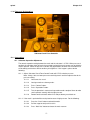
Marvell NanoLab
Member login
Lab Manual Contents
MercuryWeb
Berkeley Microlab
Chapter 4.16
Quintel Mask Aligner
(quintel - 382)
1.0
T it l e
Quintel Q4000 Mask Aligner
2.0
Pu rp o s e
The Quintel Q4000 MA (Mask Aligner) is a top and bottom side contact lithography printer with the
video-view split field microscope used for fine line lithography down to 1 micron or better. It is capable
of processing both 4- and 6-inch substrates using 7” photomasks.The quintel was recently modified to
accept 6” wafers while retaining the ability for 4” wafers and smaller substrates. This modification
duplicates many of the contact and proximity photolithography capabilities of the ksaligner allowing
NanoLab member access to two contact printers and provides a backup when one aligner is down for
maintenance or repairs. Modifications included a new 6” chuck and a new mask plate while keeping the
4” chuck.The new mask plate requires a 7” mask which matches the ksaligner’s mask
requirements.The quintel retains its IR light source and cameras for through-wafer backside alignment
for 6” wafers. The previously used mask clamp has been obviated by this modification and is no longer
available or needed. After reading this manual, the user should be able to describe a typical MA
(quintel) process for both top and backside alignment; explain the theory of operation; and state all
hazards associated with the system. After successfully completing the qualification procedures for this
tool (see Appendix 12.2), the user should be able to perform a full photolithography process for both
TSA and BSA using this system. Only trained and approved (qualified) Users may use this tool.
3.0
S co p e
The mask aligner consists of several coordinated, inter-related systems including:
4. 0
3.1
Substrate loading, holding and unloading system.
3.2
The mask supporting system.
3.3
The substrate/mask/scan/align/lock system.
3.4
The viewing system (microscope and illuminators).
3.5
The exposing system.
3.6
Use 7-inch masks.
Ap p l i ca b l e Do cu m en t s
Revision History
Quintel Q4000 Operating Manual: Manufacturer hardcopy is located in the Microlab office.
5. 0
Def in it io n s & Pr o c e s s T e rm in o lo g y
All the front panel controls are push-on, push-off buttons with indicator lamps. The buttons are
illuminated green when an option is active.
5.1
MASK VACUUM – Turns vacuum on/off to affix mask to mask chuck.
5.2
LOAD/CLEAR – Raises the wafer chuck.
5.3
CLEAR – Lowers the wafer chuck.
quintel
Chapter 4.16
5.4
SEP/CONTACT – When a wafer is loaded, the chuck will planarize with the mask and then lower
out of contact for alignment. Contact is selected to put the wafer back into contact with the mask,
after alignment and before exposing. Lights illuminate to indicate which mode is active.
5.5
EXPOSE – Exposes the wafer to UV light when activated.
5.6
Focus UP/DOWN button – Changes the microscope level in order to focus on the sample.
5.7
Red Indicating Pointer – Attached to the front of the wafer chuck assembly, indicates the theta
position (chuck rotation). Starting it centered, gives you maximum theta adjustment.
5.8
SEPARATION PRESSURE – Used to establish the separation distance for alignment. Preset by
staff.
5.9
CHAMBER VACUUM – Used in setting up the machine for vacuum printing. Preset by staff.
5.10 ILLUMINATION – Top and bottom light sources for alignment. Select the appropriate knob
position for the top and IR light source. There are also four knobs that control illumination levels
for the microscope and IR source. They all should be in off position when the machine is not in
use.
6.0
S af et y
6.1
Ultra Violet Light - The Quintel uses broadband ultraviolet light (UV) to expose photoresist.
Direct exposure to UV light can damage the cornea of the eyes and also cause sunburn. In
normal use the Quintel does not represent a hazard; however, if the lamp cover is removed or if
an exposure is made using the shutter override switch, UV injury could result.
6.2
High Voltage - Mercury arc lamps require high voltage to start and operate at potentially lethal
dc voltage. DO NOT TAMPER WITH THE ARC LAMP SYSTEM OR ARC LAMP SUPPLY. If the
lamp is off, do not turn it on. Report as equipment problem on the WAND using FAULTS.
7. 0
St at i st ic al P ro c e s s/ D at a
N/A
8. 0
Av ai l ab l e P ro c es s es , P ro c es s No t e s
8.1
8.2
The correct default idle state of the Q4000 should be as follows:
8.1.1
System power ON and HEAD LOCK ON (if not, notify staff).
8.1.2
2105C2 Illumination Controller: Power ON, Meter Select at V mode, Meter Select@
Power mode, Ch A and CI.
8.1.3
Monitor is OFF.
8.1.4
MV-200 power box is OFF. H/V split knob marker set at center. H/V switch set at V. All A
& B cross hair switches set at OFF.
8.1.5
The 7-inch dummy mask is loaded without mask vacuum and the 7-inch MA lithography
chuck is in place in the down position. No wafer is on the chuck.
8.1.6
Microscope Magnification range is 10X to 70X.
8.1.7
Normally, the vacuum on the wafer chuck switches on automatically when the wafer
chuck assembly is in. Otherwise, it switches off when it is out.
8.1.8
Maximum substrate thickness for standard operation is 5.08 mm or .2 inch.
8.1.9
Separation Gap – Preset by staff. Recommend 30 µm or .0016” with 2X objective power.
Maximum gap can be 100 µm or .004”. Recommend 20 µm or .0008” with 5X objective
power. Maximum gap can be 50 µm or .002”.
Basic Exposure Programs
-2-
quintel
Chapter 4.16
8.3
8.2.1
CONTACT CALIB – Used to select proximity printing mode. Contact staff to set it up.
8.2.2
PRESSURE CONTACT – Selects pressure contact mode, the normal operation mode.
8.2.3
VACUUM CONTACT – Mode that applies vacuum between the mask and the wafer,
used for highest resolution possible. A 0-30” vacuum gauge indicator is located on the left
hand side of the tool.
Exposing Small Dice
The 4” vacuum chuck is designed for 100 mm (4") wafers. If you use odd sized substrate, there
are several methods for adapting the 100 mm wafer chuck. You can cut a 100 mm diameter
piece of Mylar film and make a cutout for your sample. You can mount your sample to a wafer
with wax or mount your sample to wafer dicing tape. Whatever method, the goal is to obtain
good chuck vacuum. Planarization may be adversely affected by having a sample off center. It
may be necessary to place another sample opposite it for balance.
9. 0
Eq u ip m en t O p e r at io n
9.1
Enable the quintel on the wand.
9.2
All selection controls should be unlit except the POWER and HEAD LOCK.
9.3
Check if the lamp is on by the seeing if there are power and voltage readings on the lamp power
supply.
9.4
Set the Exposure Time – On the UniOp Programmable Logic Controller (PLC)
9.5
9.6
9.4.1
Select 1 from the main menu for Exp Time.
9.4.2
Press Insert, and the cursor will blink.
9.4.3
Enter the desired time, up to 999 seconds. Contact the Process Engineering Manager if
you need a longer exposure.
9.4.4
Press Enter to return to the main menu.
Set the Exposure Mode – On the UniOp Programmable Logic Controller
9.5.1
Select 2 from the main menu for Pr Modes.
9.5.2
Enter # to select desired mode, an asterisk will appear besides the process mode
selected.
9.5.3
Press Enter to return to the main menu.
Set the Operation Mode – On the UniOp PLC
9.6.1
Select 3 from the main menu for Op Modes.
9.6.1.1 Enter 1 for Exp Pressure.
9.6.1.1.1 Use in pressure contact mode for highest resolution.
9.6.1.2 Enter 2 for Contact Expose Pressure.
9.6.1.2.1 Normal contact exposure mode.
9.6.1.3 Enter 3 for IR View.
9.6.1.3.1
Activates IR viewing illumination.
9.6.1.3.2
Activates controls to move/remove IR illumination system after a
wafer is loaded/unloaded.
9.6.2
Press Enter to return to the main menu.
9.7 Loading the Mask
-3-
quintel
Chapter 4.16
9.7.1 Remove the dummy mask, and place your mask on the mask vacuum chuck with the emulsion or
chrome side facing down. The mask should rest against the banking pins in the rear left corner.
Center the
mask and mask plate over the opening and press MASK VACUUM to fix assembly to the mask vacuum chuck.
When the light is on vacuum is present to hold the mask.
9.8
Rotational Alignment of the Mask to the Microscope
9.8.1 Select MIC on the illumination selection switch if not using the IR feature. Turn up the
light intensity for the L&R microscope illuminators. Turn on the ULT9.RAK monitor and
MV-200 box. Adjust the focus on both objectives simultaneously with the black toggle
switch on the front left control panel of the tool scan, using the left hand disc to locate the
alignment marks. You will want to start with the microscope on the lowest magnification
setting (align 1 to the marks under the zoom labels on the objectives). One alignment
mark should be visible on each half of the split field image. To get both into the field of
view you may need to adjust the spacing between the split-field objectives, and/or the
rotation of the mask.
9.8.1.1
Using IR feature for backside alignment
9.8.1.1.1 Select IR/OPTL ILLUM on the illumination selection switch. Turn up
the IR illuminators. This will allow you to see the mask and the
backside of the wafer when loaded. You can also select BOTH on
the illumination selection switch, but the microscope illuminators
cannot be too bright otherwise it will wash out the IR image and you
will not be able to see it. Also, the microscope objectives must be
over the IR illuminators in order to see both the backside and mask
features. In other words, you cannot illuminate one place and look for
the image elsewhere.
9.9
9.8.2
Use the large knobs at the left-hand side and right-hand side of the microscope to adjust
the spacing between the split-field objectives, making sure they are unlocked before
adjusting. Four small knobs on the microscope bracket are for tightening the X and Y
microscope movement. Make sure these 4 small knobs are loose before making the
adjustment, because otherwise you will strip the threads on the rails, which is a very
expensive damage. Looking from side at the top of the mask with your naked eye can be
helpful for finding the right spacing. The green light of the microscope illuminator can be
seen on the mask, indicating where the objectives are aimed.
9.8.3
Mask Rotation
9.8.3.1
Press the MASK VACUUM switch to turn off the vacuum, releasing the mask.
The MASK VACUUM switch will be unlit.
9.8.3.2
Press the MASK VACUUM switch again to fix the assembly to the mask
vacuum chuck.
Loading and Aligning the Wafer
9.9.1
Slide the wafer chuck assembly towards you until it stops. With tweezers, center your
wafer on the chuck. Align flat against the white plastic flat-finder.Note that with the
modification the white plastic flat-finder will only reach a 7” wafer. For a 4” wafer, align the
wafer flat with the (flat) line scribed on the 4” chuck. Push the wafer chuck assembly 1 or
2 inches and listen to the click, which is the chuck vacuum turning on. Return the plastic
flat-finder to its original position push the assembly fully back under the mask until it hits
its stop.
9.9.2
Press the LOAD switch and the wafer will be raised under the mask and held in place.
The wafer will contact the mask to planarize the wafer to the mask; a then the
SEPARATE button should light, indicating that there is a separation between the wafer
and the mask. The instrument goes into separation mode automatically.
-4-
quintel
Chapter 4.16
9.9.3
Confirm you are in the SEPARATION mode and proceed to align your substrate or wafer.
9.9.4
Align your wafer using split field – as mask alignments on the mask should be visible
after the Step 9.9.1 procedure. There are two degrees of motion reduction available or
the align stage. It either operates at a 3:1 ratio coarse align mode or at a 150:1 ratio fine
align mode. Use the right hand joystick on the align stage to search for the alignment
marks on the wafer to match the alignment marks on the mask. Press the COARSE
button on the left front panel and the right hand side joystick simultaneously to make
coarse alignment. Next, use the theta micrometer on the left side of the stage to rotate
the alignment marks on wafer to match the mask alignment marks. Press the button on
the scan-align stage joystick on the left front side to move the alignment marks into the
viewing position under both objectives. The scan-align mode moves the stage and the
mask together.
9.9.5
When alignment is complete, pressing the CONTACT button will bring the wafer into
contact with the mask. Confirm the alignment is correct. If an adjustment is necessary,
press the SEPARATE button and realign.
9.10 Procedure for Backside Alignment
Alignment marks must be within the IR viewing windows on the wafer chuck. The position of the
light pipes may be changed by adjusting the thumbscrews on the light pipe insertion assembly.
The default objective separation of 51.15 mm (2.25”) is set for current 4” wafer chuck. The
infrared light pipes work by projecting infrared light up from the wafer chuck, through the wafer.
Features on the backside of the wafer cast shadows up to the focal plane, located at mask level.
To generate an IR image, these light pipes must be positioned below the split-field microscope
objectives. If the pipes are grossly out of alignment, no image will be seen. If the pipes are slightly
out of alignment, shadows will be cast up at angles, thereby affecting alignment. Adjust each pipe
grossly so that it illuminates respective to the target. Perform a fine pipe alignment by watching
the motion of backside features as you adjust the pipes. It is usually possible to determine when
the pipe is directly below the target by watching the rate at which the shadow moves as you move
the pipe. The motion of the backside image should be at a minimum when the pipe is directly
below its target. Follow the same procedure as Steps 9.6 to 9.9.
9.11 Expose the Wafer – Press EXPOSE button. The Expose position provides a reflector to direct
the UV light down to expose the wafer.
9.11.1 After exposure, the chuck lowers automatically. Pull the wafer chuck assembly out all the
way towards you. Remove the wafer with tweezers, and then push the wafer chuck
assembly back in.
9.12 Removing the Mask
9.12.1 To remove the mask, press the MASK VACUUM button (light will go off) to release the
mask from the mask vacuum chuck. You can now lift the mask out.Place the mask right
side up on top of the left cover on the Quintel aligner
9.13 System Shutdown
9.13.1 Illumination selection switch should be off.
9.13.1.1 All four light control knobs fully counterclockwise.
9.13.1.2 IR View should be off on the Op Modes.
9.13.2 Wafer chuck down.
9.13.3 Ensure the substrate chuck is pushed entirely in.
9.13.4 Mask Vacuum on.
9.13.5 Power off on Ultrak monitor and MV-200.
-5-
quintel
Chapter 4.16
9.13.6 Do not turn off main POWER, HEAD LOCK or UniOp.
9.14 Measure Lamp Intensity
2
9.14.1 The exposure power is approximately 8.3 to 15.0 14.2 mW/cm for I-line.
9.14.2 Obtain Karl Suss UV Intensity Meter – Model 1000 from the drawer next to the Karl Suss
Aligner.
9.14.3 Select 4 from the main menu for Controls Mode on the OniOp PLC.
9.14.4 Enter 3 for Expose Test on the menu. The optical head will rise.
9.14.5 Connect the I-line probe to the UV intensity meter. Turn on the power on the intensity
meter. Put the I-line probe in its holder and place it on the center of the dummy mask
from the side of the tool.
9.14.6 Enter 2 for Manual Shutter on the menu.
9.14.7 You can read the intensity on the meter.
9.14.8 Press 2 to turn off Manual Shutter.
9.14.9 Take I-line probe off the aligner. Disconnect the probe on the intensity meter. Turn off the
power on the intensity meter. Place everything back in order and store it back in the
drawer by the Karl Suss Aligner.
9.14.10 Press 3 to lower optical head.
9.14.11 Press Enter to return to the main menu
10 . 0 T ro u b l e sh o o t in g G u i d el in e s
10.1 During SEP and press CONT modes, the flow of gas out of the chamber can make a hissing
noise. If this happens, you may wish to press the CLEAR button, unload the wafer, pull the wafer
chuck out, and wipe the seal around the edge of the chuck with a clean wipe.
10.2 No light during exposure. If this happens, check the power on lamp power supply.
10.3 Wafer chuck gets stuck on mask. Load wafer chuck up without wafer will make vacuum hold on
to mask. If this happens, do the following under Main Menu to release the vacuum:
10.3.1 Press 4- Controls.
10.3.2 Press Right Arrow → button.
10.3.3 Press 2 [ ] Chuck Vac Off.
10.3.4 Press Clear button.
10.3.5 Press ENTER button on UniOp to return to Main Menu.
-6-
quintel
Chapter 4.16
11 . 0 F ig u r es & Sc h e m a t i c s
Substrate Chuck Force Controller
12.0 Ap p en d ic e s
12.1 Substrate Separation Adjustment
The normal separation setting between the mask and the substrate is 15 PSI. When pressure is
too high, the substrate chuck will push the mask too hard and the mask vacuum can not hold the
mask in position. When the pressure is too low, the gap between substrate chuck and the mask
will be too big and the focus will be too blurry for alignment. If this happens, please do the
following:
12.1.1 Adjust “Substrate Chuck Force Control” knob until 15 PSI or desire pressure.
Note: Always start at a lower pressure to avoid hysteresis and then adjust to the desire
pressure setting.
12.1.1.1
Load a mask as usual.
12.1.1.2
Load your wafer or a dummy wafer.
12.1.1.3
Press “Contact” button.
12.1.1.4
Press “Separation” button.
12.1.1.5
Test the operation in contact and separation mode a couple of times to make
sure it operates correctly with the right pressure.
12.1.1.6
Remove wafer and mask when finish and put dummy mask back on.
12.1.2 If the mask is pushed off the mask plane because of high pressure. Do the following:
12.1.2.1
Press the “Clear” button to unload the wafer.
12.1.2.2
Pull the stage out and push it back in.
12.1.2.3
Press “Mask Vac” button to release the mask vacuum.
-7-
quintel
Chapter 4.16
12.1.2.4
Center the mask back on the mask plane and press “Mask Vac” button to
activate the vacuum on the mask.
12.1.2.5
Adjust “Substrate Chuck Force Control” knob until 15 PSI or desire pressure.
12.1.2.6
Press “Load” to load the wafer.
12.1.2.7
Press “Contact” button.
12.1.2.8
Press “Separation” button.
12.1.2.9
Test the operation in contact and separation mode a couple of times to make
sure it operates correctly with the right pressure.
12.1.2.10 Remove wafer and mask when finish and put dummy mask back on.
12.1.2.11 If the operation is not working right with the new pressure setting, repeat step
12.1.2.1 to 12.1.2.9.
12.1.3 If the focus for alignment is blurry because of low pressure. Do the following:
12.1.3.1
Press the “Clear” button to unload the wafer.
12.1.3.2
Pull the stage out and push it back in.
12.1.3.3
Adjust “Substrate Chuck Force Control” knob until 15 PSI or desire pressure.
12.1.3.4
Press “Load” to load the wafer.
12.1.3.5
Press “Contact” button.
12.1.3.6
Press “Separation” button.
12.1.3.7
Test the operation in contact and separation mode a couple of times to make
sure it operates correctly with the right pressure.
12.1.3.8
Remove wafer and mask when finish and put dummy mask back on.
12.1.3.9
If the operation is not working right with the new pressure setting, repeat step
12.1.3.1 to 12.1.3.7.
12.2 Qualification Procedures
12.2.1 After studying the Q4000 User Manual, potential new users should arrange ahead of time
to have an existing user review the MA operation. Casual questioning (e.g. "Hey, can you
review this with me for a moment?") is not to be considered an official review period.
12.2.2 The first question that should be asked is whether Section 4.16 - Quintel Mask Aligner on
the web and the equipment header file has been thoroughly reviewed? If not, the current
user should insist that it be reviewed before the meeting.
12.2.3 The "meeting" between the current and new user should be scheduled for enough time to
explain equipment operation; Loading and unloading the mask and substrate, top side
alignment using the top microscope, back side alignment using IR, the exposure process,
and a review of system errors. (I cannot see this taking less than 60 minutes as subtleties
of the MA process are sure to come up for discussion). Equipment time and dummy
wafer should be recharged to new user’s account.
12.2.4 Step 12.2.3 should be done at least twice with two different current users.
12.2.5 Upon successful completion of Step 12.2.4, new users should take the MA Users Test.
Tests are administered by Microlab office staff, and are graded by Microlab staff (Kim
Chan). Estimate 2-5 days for grading. The idea of the test is to simply make sure all new
users understand the material. Satisfactory completion of this test will enable the user to
meet with a Superuser for qualification.
-8-
quintel
Chapter 4.16
12.2.6 Superusers will first ask, “who trained you?” of the new user. “Training” implies
adequately following Steps 12.2.1-12.2.4 above. The users identified as being the ones
who did the training will be responsible for the information conveyed by the new user
during the qualification. It is suggested that the test be reviewed with another user while
at the Quintel aligner tool before taking the final oral qualification with the superuser.
12.2.7 Description of Alignment Target Placement – An optional standard spacing for the
alignment marks is 76.2 mm or 3 inches apart on a 4” substrate along the X-axis and
center on the substrate along the Y-axis. Use 51.15 mm or 2.25 inches spacing if
backside alignment is needed.
12.3 Quintel Q4000 MA Study Guide
Be sure to know….
12.3.1
What to do with a malfunctioning lamp.
12.3.2
Possible ultraviolet hazards with quintel.
12.3.3
Scan vs. align stage.
12.3.4
Loading a mask.
12.3.5
Getting alignment marks into the field of view.
12.3.6
How NOT to strip threads on rails.
12.3.7
Rotating the mask.
12.3.8
After aligning wafer flat to the flat finder.
12.3.9
What the white plastic flap is for.
12.3.10 SEP button.
12.3.11 When alignment is complete.
12.3.12 Setting exposure timer, how to set longer times.
12.3.13 Removing the mask.
12.3.14 Shutting down the machine.
12.3.15 The 5 steps to doing backside/IR alignment.
12.3.16 If the airflow whistles.
12.3.17 Typical intensity of UV lamp; measuring it.
12.3.18 Calculating exposure time.
-9-