1
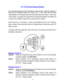
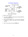
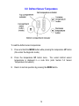
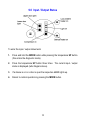
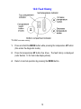
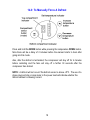
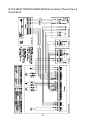
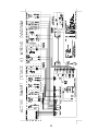
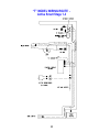
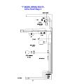
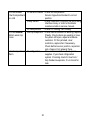
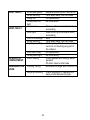
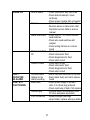
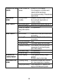
Active Smart™
Refrigerators
517702
Fisher & Paykel Appliances © 2003
Reprinted July 2003
Contents
1.0 Fault Code Display Status............................................................................3
2.0 Thermistor Sensors Resistance Table.........................................................7
3.0 Mode Status - Versions 1, 2, 3 and 4..........................................................8
4.0 Mode Status - Version 4.1...........................................................................9
5.0 Sensor Temperature Conversion ...............................................................10
6.0 PC Sensor Temperature ............................................................................11
7.0 FC Sensor Temperature.............................................................................12
8.0 Defrost Sensor Temperature......................................................................13
9.0 Input / Output Status ..................................................................................14
10.0 Fault History .............................................................................................15
11.0 Software Version ......................................................................................16
12.0 Input / Output Faults.................................................................................17
13.0 Download Data .........................................................................................18
14.0 To Manually Force A Defrost....................................................................19
15.0 Service Manual Wiring Diagram...............................................................20
“B” MODEL WIRING ROUTE - Active Smart Stage 1-3 ...............................24
“T” MODEL WIRING ROUTE - Active Smart Stage 1-3..............................25
“B” MODEL WIRING ROUTE - Active Smart Stage 4...................................26
“T” MODEL WIRING ROUTE - Active Smart Stage 4...................................27
16.0 Service Reference “B” Models .................................................................28
17.0 Service Reference “T” Models .................................................................35
18.0 Fault Finding Flow Chart - (Listing) ..........................................................39
A. System Faults............................................................................................40
B. Temperature Faults ...................................................................................46
C. Sensor Faults ............................................................................................50
D. Auxiliary Faults..........................................................................................54
2
1.0 Fault Code Display Status
If a fault should develop in the temperature measurement or defrost systems (or
fans and low ambient heaters on Version 4.1), a fault code will be shown
automatically on the display and the fault audio alarm will sound. When any
control button is pressed, the audio alarm is turned off although the display will
continue to be “flashed” instead of the normal “back-lit” display.
Fault codes 8 to 13 (Version 4.1 only) are indicated by fault code 7 flashing.
Enter current I/O fault log (refer Section 4.0 Mode Status) to determine which I/O
fault is current.
The faults and their respective fault code that can be checked and serviced in
the field are as follows:
(13)
(12)
(11)
(10)
(9)
(8)
Display Code: 0
Reason:
Action:
Faulty FC temperature sensor (the resistance is out of normal range:
resistance greater than 45K Ohms).
Check resistance of FC temperature sensor (refer Section 2.0
Thermistor Sensors Resistance Table and Section 15/C4 Sensors PC / FC). If faulty, replace.
Display Code: 1
Reason:
Action:
Faulty FC temperature sensor (the resistance is out of normal range:
resistance less than 660 Ohms).
Check resistance of FC temperature sensor (refer Section 2.0
Thermistor Sensors Resistance Table and Section 18/C4 Sensors PC / FC). If faulty, replace.
3
Display Code: 2
Reason:
Action:
Faulty defrost temperature sensor (the resistance is out of normal
range: resistance greater than 45K Ohms).
Check resistance of defrost temperature sensor (refer Section 2.0
Thermistor Sensors Resistance Table and Section 18/C4 Sensors PC / FC). If faulty, replace.
Display Code: 3
Reason:
Action:
Faulty defrost temperature sensor (the resistance is out of normal
range: resistance less than 660 Ohms).
Check resistance of defrost temperature sensor (refer Section 2.0
Thermistor Sensors Resistance Table and Section 18/C4 Sensors PC / FC). If faulty, replace.
Display Code: 4
Reason:
Action:
Faulty PC temperature sensor (the resistance is out of normal range:
resistance greater than 45K Ohms).
Check resistance of PC temperature sensor (refer Section 2.0
Thermistor Sensors Resistance Table and Section 18/C4 Sensors PC / FC). If faulty, replace.
Display Code: 5
Reason:
Action:
Faulty PC temperature sensor (the resistance is out of normal range:
resistance less than 660 Ohms).
Check resistance of PC temperature sensor (refer Section 2.0
Thermistor Sensors Resistance Table and Section 18/C4 Sensors PC / FC). If faulty, replace.
Display Code: 6
Reason:
Action:
Defrost was aborted after 60 minutes. This has happened in the last
two defrosts therefore probably defrost heater failure.
Check defrost heater (refer Section 18/C3 Defrost Sensor). If faulty,
replace.
4
Display Code: 7 (Stage 4 only)
Reason:
Action:
Power / control module failed self-test.
Replace power / control module
Display Code: 7 (Stage 4.1)
Reason:
Action:
I/O (Input / Output) fault OR power / control module failed self test
Check I/O fault logs – refer notes on mode status Version 4.1
(Section 4.0). If no I/O fault then replace power / control module.
Display Code: 8 (Stage 4.1)
Reason:
Action:
Low ambient heater low current fault – the low ambient heater is
drawing less current than expected. Either the heater or wiring is
open circuit or the heater is faulty.
Check wiring and connections. Check heater resistance.
Display Code: 9 (Stage 4.1)
Reason:
Action:
Low ambient heater high current fault – the low ambient heater is
drawing more current than expected. Either there is a short in the
heater or wiring, or the heater is fault.
Check wiring and connections. Check heater resistance.
Display Code: 10 (Stage 4.1)
Reason:
Action:
PC fan low current fault – the PC fan is drawing less current than
expected. Either the wiring is open circuit or the fan is faulty.
Check PC fan wiring and connections, check fan function.
Display Code: 11 (Stage 4.1)
Reason:
Action:
PC fan high current fault – the PC fan is drawing more current than
expected. Either there is a short in the wiring or the fan is faulty.
Check PC fan wiring and connections, check fan function.
Display Code: 12 (Stage 4.1)
Reason:
Action:
FC fan low current fault – the FC fan is drawing less current than
expected. Either the wiring is open circuit or the fan is faulty.
Check FC fan wiring and connections, check fan function.
5
Display Code: 13 (Stage 4.1)
Reason:
Action:
FC fan high current fault – the FC fan is drawing more current than
expected. Either there is a short in the wiring or the fan is faulty.
Check FC fan wiring and connections, check fan function.
6
2.0 Thermistor Sensors Resistance Table
Temperature
(oC)
Resistance
(K Ohms + 5%)
-30.0
25.17
-25.0
19.43
-20.0
15.13
-15.0
11.88
-10.0
9.392
-5.0
7.481
0.0
6.000
5.0
4.844
10.0
3.935
15.0
3.217
20.0
2.644
25.0
2.186
30.0
1.817
35.0
1.518
40.0
1.274
45.0
1.075
50.0
0.9106
7
3.0 Mode Status Versions 1, 2, 3 and 4
To enter the diagnostic mode:
Press and hold the MODE button while pressing the temperature UP button (this
enters the diagnostic mode).
The lights indicate the PC sensor temperature.
Press the up button.
1 time
= FC sensor temperature
2 times = Defrost sensor temperature
3 times = Inputs / outputs status
4 times = Current sensor status
5 times = Fault history
6 times = Software version
To enter the data down load mode:
Press and hold the MODE button while pressing the temperature UP button,
then press the temperature DOWN button (this enters the data down load
mode).
8
4.0 Mode Status Version 4.1
To enter the diagnostic mode:
Press and hold the MODE button while pressing the temperature UP button (this
enters the diagnostic mode).
The lights indicate the PC sensor temperature.
Press the up button.
1 time
= FC sensor temperature
2 times = Defrost sensor temperature
3 times = Inputs / outputs status
4 times = Current sensor status
5 times = Fault history
6 times = Software version
7 times = Current I/O fault log
8 times = Previous I/O fault log
To enter the data down load mode:
Press and hold the MODE button while pressing the temperature UP button,
then press the temperature DOWN button (this enters the data down load
mode).
9
5.0 Sensor Temperature Conversion
To obtain the temperature of either compartment sensor or defrost sensor:
1.
Enter the diagnostic mode (refer Section 3.0 Mode Status) and scroll to the
appropriate sensor temperature.
2.
Add up the binary number indicated by the L.E.D. light pattern (refer figure
below).
3.
Subtract 40 from the result to get the temperature.
Example:
Add up the number corresponding to each L.E.D. which is on:
0.5 + 4 + 8 + 32 = 44.5
Subtract 40 from the result
44.5 - 40 = 4.5 oC
Hence the temperature is 4.5oC
10
6.0 PC Sensor Temperature
To read the PC sensor temperature:
1.
Press and hold the MODE button while pressing the temperature UP button
(this enters the diagnostic mode).
2.
The current PC sensor temperature is displayed in a code form (refer
Section 5.0 Sensor Temperature Conversion).
3.
Return to normal operation by pressing the MODE button.
CAUTION: In reading temperatures there is a need to enter the required mode
when the door is first opened as all temperature readings are only sensor
temperature / air temperatures and these will change rapidly with the increase in
air temperature as soon as the door is opened.
11
7.0 FC Sensor Temperature
To read the FC sensor temperature:
1.
Press and hold the MODE button while pressing the temperature UP button
(this enters the diagnostic mode).
2.
Press the temperature UP button once. The current FC sensor temperature
is displayed in a code form (refer Section 5.0 Sensor Temperature
Conversion).
3.
Return to normal operation by pressing the MODE button.
12
8.0 Defrost Sensor Temperature
To read the defrost sensor temperature:
1.
Press and hold the MODE button while pressing the temperature UP button
(this enters the diagnostic mode).
2.
Press the temperature UP button twice. The current defrost sensor
temperature is displayed in a code form (refer Section 5.0 Sensor
Temperature Conversion).
3.
Return to normal operation by pressing the MODE button.
13
9.0 Input / Output Status
To enter the input / output status tests:
1.
Press and hold the MODE button while pressing the temperature UP button
(this enters the diagnostic mode).
2.
Press the temperature UP button three times. The current input / output
status is displayed (refer diagram above).
3.
If a device is on or a door is open the respective L.E.D. lights up.
4.
Return to normal operation by pressing the MODE button.
14
10.0 Fault History
To enter the fault history:
1.
Press and hold the MODE button while pressing the temperature UP button
(this enters the diagnostic mode).
2.
Press the temperature UP button five times. The fault history is displayed
(refer Section 1.0 for fault code display status).
4.
Return to normal operation by pressing the MODE button.
15
11.0 Software Version
Used to indicate the version of software in the control module.
To obtain the version of software:
1.
2.
3.
Press and hold the MODE button while pressing the temperature UP button
(this enters the diagnostic mode).
Press the temperature UP button six times.
Return to normal operation by pressing the MODE button.
In the example shown below the software version is 1.2. This is indicated
through a binary code count as shown on the control board interface.
Indicating version 1.2
16
12.0 Input / Output Faults
(Version 4.1 only)
To enter the input / output fault log:
1.
Press and hold the MODE button while pressing the temperature UP button
(this enters the diagnostic mode).
2.
Press the temperature UP button seven times. Any Input / Output faults (8
to 13) are displayed (refer Section 1.0 for fault code display status).
4.
Return to normal operation by pressing the MODE button.
17
13.0 Download Data
To download data into your laptop:
1.
Press and hold the MODE button while pressing the temperature UP button
(this enters the diagnostic mode).
2.
Press the temperature DOWN button once. A RED L.E.D. will show at the
bottom of the temperature scale.
3.
Place the INTERFACE PEN over the top of the RED L.E.D. until the
downloading has been completed.
4.
Return to normal operation by pressing the MODE button.
Notes on data downloading:
An interface MK2 downloading pen is needed, part number 425930B, and the
FISHER & PAYKEL Smart Tool diagnostic programme loaded on to a laptop
computer.
18
14.0 To Manually Force A Defrost
Press and hold the MODE button while pressing the temperature DOWN button.
Note there will be a delay of 2 minutes before the element starts to heat after
going into this mode.
Also, after the defrost is terminated, the compressor will stay off for 4 minutes
before restarting and the fans will stay off a further 30 seconds after the
compressor has started.
NOTE: A defrost will not occur if the defrost sensor is above +8oC. The use of a
phase plug and clip on amp meter in the power lead will indicate whether the
defrost element is drawing current.
19
15.0 Service Manual Wiring Diagram
(Phase 1) Power And Console Board
20
21
ACTIVE SMART WIRING DIAGRAM (With Butter Conditioner) Phase 2 Power &
Console Board
W
W
W
W
22
W
W
W
W
23
W
W
W
W
W
W
W
W
“B” MODEL WIRING ROUTE Active Smart Stage 1-3
24
“T” MODEL WIRING ROUTE Active Smart Stage 1-3
25
“B” MODEL WIRING ROUTE Active Smart Stage 4
26
“T” MODEL WIRING ROUTE Active Smart Stage 4
27
16.0 Service Reference “B” Models
PC TOO COLD * Ambient heater open
Cold Crispers
circuit
Ice in crispers * PC fan fitted upside
down
* PC fan not going
- Check continuity of element using
multimeter.
- Fan hub to be facing PC
- Check voltage to plug, check wiring
polarity
* Air leakage base duct - Seal with foam tape on duct divider
cover
spigot
* PC sensor location
- Remove insulation pad
Cold
* PC fan not going
- Check for mechanical obstruction
Compartment
- Check power to plug
Warm Top
- Check polarity
- Replace fan
- Check for broken wires.
Total
* FC fan not going
- Check power to plug
Compartment
- Check for broken wires
Too Cold
- Check polarity
- Replace fan
* Short of gas
- Check run percentage, if high,
check evaporator
- Check fully flooded evaporator,
check for leak.
* PC sensor inaccurate - Check calibration of sensor ice point
using interface binary or refer to
thermistor resistance table in
service manual.
28
PC TOO WARM
* PC fan not going - Check power to plug
Warm Compartment
- Check polarity
Cool Bottom
- Check for broken wires
- Replace fan
- Check fan is not jammed with ice
or anything else.
* PC fan upside
- Fan hub to be facing FC refit.
down
* Return duct iced - De-ice duct area behind chassis
up
- Check PC duct insulation for good
seal in return duct.
- Check doors are sealing.
Total Compartment * PC duct blocked - Defrost evaporator chassis
Warm
- Check for door seal
* Evaporator ice up - Check defrost element, check
continuity
- Check door seal / door left open
* No refrigeration - Does cabinet run? If no check
power supplies. If yes, check
refrigeration system. If running,
check for live frost / fully flooded
evaporator. If not check for leak.
* Fans not working - Is there a 12 volt supply, PC light
working.
- 12 volt supply to console board,
check harness and plugs.
- 12 volt AC secondary of
transformer open circuit.
29
FC TOO COLD * FC sensor location - Check set temperature
Total Compartment
Sensor clipped and located in correct
too cold
position.
* Faulty sensor
- Check calibration of sensor ice point using
interface binary or refer to thermistor
resistance table in service manual.
* PC faulty sensor - Check PC cooling, fan running
FC TOO WARM * Iced up evaporator - Check defrost element is working, replace
Bottom warm top
if faulty. Check doors are sealing or have
frozen
they been left open, adjust and advise
customer. FC fan jammed, clear
restriction, replace fan if necessary.
Check defrost sensor position, reposition
onto chassis if not already there.
Total Compartment * No refrigeration - Does cabinet run? If no check power
Warm
supplies. If yes check refrigeration
system. If running check for live frost /
fully flooded evaporator, if not check for
leak.
30
TOTAL CABINET * No refrigeration
TOO WARM
- Does cabinet run? If no check power
supplies. If yes check refrigeration
system. If running, check for live frost /
fully flooded evaporator. If not, check for
leak.
- Compressor is not running, check power
module voltage outputs. Check
compressor and ancillaries .
- Check reed switches are working OK.
FC COOLING PC * Iced up
- Check defrost circuit continuity
WARMING
evaporator
- Doors sealing, adjust
- PC fan is running, if not refer PC too
warm
* Iced up return
- De ice duct area
duct
- check PC duct insulation for good seal in
`
return duct
- Check doors are sealing
ALARM ON
* Defrost heater - Check console for any fault code
- Check defrost element check continuity
- Check power module 230v output
* Sensors
- Check console for fault codes 0-5
- Sensors above or below limit, refer
thermistor service table in service
manual
* Alarm board fault - Check that PC / FC doors activate reed
switches
- Check also reed switches with magnet
- Check wiring harness to console board
* DC fan fault PC & - Check open circuit
FC
- Check console for fault
- Check diagnostics for fault
- Check short circuit
* Ambient heater - Check open circuit
- Check console for fault
- Check diagnostics for fault
- Check short circuit
31
32
FAULT
* Console board but - Alarm has been switched off by
DISPLAYED, NO
no alarm sounding user
ALARM
- Piezo alarm faulty on board, replace
board
* Blown bulb
- Check power supply to socket 7
LIGHT NOT
volts, if nil check plug at board
FUNCTIONING
- Check continuity of bulb, if nil
replace
* Cabinet type
- Console board not initialised, close
FC door and press any button
* Poor connection
- Spread halogen bulb legs
- Lamp holder, replace where
possible
- Connector on control module
CONSOLE NO
* Power module no - Is there a 12 volt supply
LED LIGHTS
power
- 12 volt supply to console board,
check harness and plugs
- 12 volt AC secondary of transformer
open circuit
- Initiate cabinet.
RASPBERRY
* Wrong control
- Initialise console module, close FC
NOISE
module
door and push any button on
console module
33
NOISY FAN PC
*
*
*
*
Ice around gasket
Wires touching
Faulty fan
Wires pulled too
tight
* Ice on cover
- Replace assembly with new fan kit
- Tuck wires away from fan blade
- Fit replacement
- Re route wires
- Clear ice off cover and check doors
are sealing
* Ice on grill
- Clear ice off grill and check doors
are sealing
* Fan off mountings - Refit
* Wires touching
- Tuck wires away from fan blade
* Capillary touching - Shift capillary from fan area, make
sure it is not touching any part of
the cabinet
* Fan motor noisy
- Fit replacement
* Wires pulled tight - Re route wiring
ICE BUILD UP
* Doors sealing
- Check gaskets are sealing, adjust
COMPARTMENT
gaskets
- Fit drain valve to drain tube
REFRIGERATION * Popping, farting
- Evacuate recharge with ISCEON 49
NOISE
* Gurgling, whistling - Check alignment of capillary and
apply sound dampening tape
NOISY FAN FC
34
17.0 Service Reference “T” Models
PC TOO COLD * FC fan not going
Total Compartment
Too Cold
* Short of gas
* PC sensor
inaccurate
PC TOO WARM * Evaporator ice up
Total Compartment
Warm
* No refrigeration
* Fans not working
* Power module
failure
* PC delivery duct
blocked
35
- Check power to plug
- Check polarity
- Replace fan
- Check run percentage, if high check
evaporator
- Check fully flooded evaporator,
check for leak
- Check calibration of sensor ice point
using interface binary or refer to
thermistor resistance table in
service manual
- Check defrost element, check
continuity
- Check door seal / door left open
- Does cabinet run? If no, check
power supplies. If yes, check
refrigeration system
- If running, check for live frost / fully
flooded evaporator, if not check for
leak
- Is there a 12 volt supply, PC light
working
- 12 volt supply to console board,
check harness and plugs
- 12 volt AC secondary of transformer
open circuit
- Check fan is not a Y97-16 stalling
on fan speed 3
- Is compressor running, is there a 12
volt supply from module to console
board. If not, replace board
- De ice area behind chassis
FC TOO COLD * FC sensor location - Check set temperature
Total Compartment
- Sensor clipped and located in correct
Too Cold
position
* Faulty sensor
- Check calibration of sensor ice point
using interface binary or refer to
thermistor resistance table in service
manual
* PC faulty sensor - Check PC cooling, fan running
FC TOO WARM * No refrigeration - Does cabinet run? If no check power
Total Compartment
supplies. If yes, check for live frost /
Warm
fully flooded evaporator, if not check
for leak
TOTAL CABINET * No refrigeration - Does cabinet run? If no check power
TOO WARM
supplies. If yes, check refrigeration
system
- If running, check for live frost / fully
flooded evaporator
- If not, check for leak
- Compressor is not running, check
power module voltage outputs
- Check compressor and ancillaries
FC COOLING PC * Iced up evaporator - Check defrost circuit continuity
WARMING
- Doors sealing, adjust
- PC fan is running, if not refer PC too
warm
36
ALARM ON
FAULT
DISPLAYED
NO ALARM
LIGHT NOT
FUNCTIONING
* Defrost heater
- Check console for any fault code
- Check defrost element, check
continuity
- Check power module 230 volt output
* Sensors
- Check console for fault codes 0-5
- Sensors above or below limit, refer
thermistor service table in service
manual
* Alarm board fault - Check that PC / FC doors activate
reed switches
- Check also reed switches with
magnet
- Check wiring harness to console
board
* DC fan fault PC & - Check open circuit
FC
- Check console for fault
- Check diagnostics for fault
- Check short circuit
* Ambient heater
- Check open circuit
- Check console for fault
- Check diagnostics for fault
- Check short circuit
* Console board
- Alarm has been switched off by user
display but no
- Piezo alarm faulty on board, replace
alarm sounding
board
* Blown bulb
- Check power supply to socket 7
volts, if nil check plug at board
- Check continuity of bulb, if nil replace
* Cabinet type
- Console board not initialised, close
FC door and press any button.
* Poor connection - Spread halogen bulb legs
- Lamp holder, replace where possible
37
CONSOLE NO LED * Power module no - Is there a 12 volt supply?
LIGHTS
power
- 12 volt supply to console board,
check harness and plugs
- 12 volt AC secondary of transformer
open circuit
RASPBERRY
* Wrong control
- Initialise console module, close FC
NOISE
module
door and push any button on
console module
NOISY FAN PC
* Ice around gasket - Replace assembly with new fan kit
* Wires touching
- Tuck wires away from fan blade
* Faulty fan replace - Fit replacement
assy with new fan
kit
NOISY FAN FC
* Ice on cover
- Clear ice off cover and check doors
are sealing
* Ice on grill
- Clear ice off grill and check doors
are sealing
* Fan off mountings - Refit
* Wires touching
- Tuck wires away from fan blade
* Capillary touching - Shift capillary from fan area and
make sure it is not touching any
part of the cabinet
* Fan motor noisy - Fit replacement
* Wires too tight
- Re route wiring
ICE BUILD UP
* Doors sealing
- Check gaskets sealing, adjust
COMPARTMENT
gaskets
- Fit drain valve to drain tube
REFRIGERATION * Popping farting
- Evacuate recharge with ISCEON
NOISE
49, check alignment of capillary
* Gurgling whistling - Check alignment of capillary and
apply sound dampening tape
38
18.0 Fault Finding Flow Chart - (Listing)
A)
System Faults
A1
A2
A3
A4
A5
A6
B)
Temperature Faults
B1
B2
B3
B4
C
FC too cold, PC too warm
FC PC warm
Ice / Condensation forming
PC too cold
Sensor Faults
C1
C2
C3
C4
D
Nothing in cabinet operating
Compressor
Compressor running, but warm PC / FC
Console Fault Code
No power to Power and Control modules
Refrigerant System
FC stratification
PC stratification
Defrost sensor
PC or FC sensor fault code
Auxiliary Faults
D1
D2
D3
D4
D5
Defrost heater
Door alarm operation
Fans - PC / FC
No Light
Low ambient heater
39
A. System Faults
A1 Nothing In Cabinet Operating
40
A2 Compressor
41
A3 Compressor Running, But Warm PC / FC
42
A4 Console Fault Code
43
A5 No Power To Power And Control Modules
44
A6 Refrigerant System
45
B. Temperature Faults
B1 FC Too Cold, PC Too Warm
46
B2 FC / PC Warm
47
B3 Ice / Condensation Forming
48
B4 PC Too Cold
49
C. Sensor Faults
C1 FC Stratification
50
C2 PC Stratification
51
C3 Defrost Sensor
52
C4 PC Or FC Sensor Fault Code
53
D. Auxiliary Faults
D1 Defrost Heater
54
D2 Door Alarm Operation
55
D3 Fans – PC / FC
56
D4 No Light
57
D5 Low Ambient Heater
58