1
...,...w "".
~
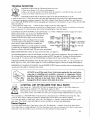
SLOT MACHINES
The
Complete
Service
Manual
For
(SERIES E 1980-1986 )
'$19.95
Marshall Fey
(]S~SLOT
The Complete Service Manual For Series E 1980-1986
Marshall Fey
Table of Contents
Getting Acquainted ................................. 2
Introduction to the Bally Electronic Slot .. 3
Built-In Test Functions ............................ 5
Initial Set-Up (Maintenance Tests)
Step 1: "Start of New Game" ................ 6
Step 2: Load (Output) Test ................... 7
Step 3: Switch Test .............................. 10
Step 4: Hopper Test ............................. 12
Step 5: Reel Reader Test ...................... 13
Step 6: Memory Check ........................ 14
Step 7: Maintenance Meter Display Test 15
Step 8: Game Functional Test ...... .... .... 17
6-Diget Led Display............................... 8
14 Diget Double Progressive Display...... 9
Normal Operation .................................. 18
Bookkeeping Meters .............................. 19
Game Condition Malfunction Codes ....... 20
Standard Options .................................... 23
Game Condition Malfunction Chart ......... 26
Miscellaneous Features ........................... 27
Service & Adjustments ........................... 28
Reel Mechanism Adjustments .............. 28
Reel Reader Assembly Adjustment ...... 32
Hopper Payout Service & Adjustment. ... 33
Handle Mechanism Service ................ .... 35
Molex Plug Service ................................ 36
State Laws for Possession of SERIES E .. 36
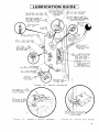
Lubrication of Handle Mechanism .......... 37
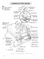
Lubrication of Reel Mechanism .............. 38
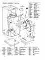
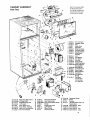
Cabinet Assembly..... .................. ....... .... 40
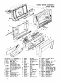
Front Door Assembly .............................. 42
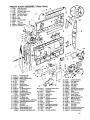
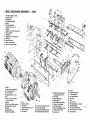
Reel Mechanism Assembly..................... 44
Reel Mechanism Boards .......................... 46
Hopper Control Boards ............................ 47
Hopper Payout Unit Assembly ................. 48
Handle Mechanism Assembly .................. 49
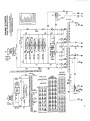
Game Power Distribution Schematic ........ 50
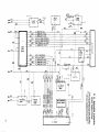
P.C. Board Power Distribution Schematic. 51
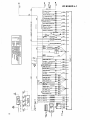
I/O Board J-1 Schematic ......................... 52
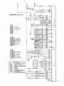
I/OBoard J2 & J3 Schematic. ..... .... .... ..... 53
I/O Board Assembly............................... 54
Sound Board Assembly ........................... 55
MPU Board Assembly............................ 56
Power Supply Board .............................. 58
Delay Relay Board ....................... .......... 59
Slot Stimulator Test Station .................... 59
Cabinet Cable Connections .... ............ ..... 60
Triacs ..................................................... 61
Description of Boards ..... ............. ........... 61
Game Transformers ................................. 62
Input/Output Voltage Schematic.. ............ 62
Trouble Shooting .................................... 63
Dealers (Parts & Repairs) ........................ 63
Other Informative Liberty Belle Books... 64
Published by
Liberty Belle Books
2925 West Moana Lane
Reno. 89509·6011
First Edition 1995
ISBN No. 0-9623852-3-9
Library of Congress
Catalog Card No. 95-75025
© 1995
A portion of the contents of this book was reproduced from six Bally SERIES E Manuals. The use of this
material was granted through the generosity of Mr. Hans Kloss, President & COO, Bally Gaming, Inc., in a
contract dated December 17. 1994. This subject matter remains the property of Bally Gaming International. Inc.
All the revisions and new material are the property of Liberty Belle Books.
No part of this book may be reproduced without written permission, except in critical articles and reviews.
Special appreciation for numerous contributions are extended especially to Tim Becke. Bally Gaming. Inc.;
and to Betty Mann. Bally Gaming. Inc.; and to John Riggs. Jr.• Digitronics.
Liberty Belle Books makes no representation or warranty with respect to the procedures contained in this
publication or the results to be achieved in following such instruction procedures.
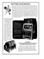
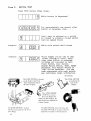
GETTING ACQUAINTED
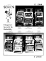
In 1980, after sixteen years of manufacturing Electro-Mechanical slots. Bally. with
approximately 90% of the domestic market. introduced the SERIES E- I 000. This
second generation of machines, a continuation of the earlier models, featured solid
state electronic circuitry that replaced the ageing electro-mechanical components.
These microprocessor driven slots were popular with the casinos offering better
dependability and security. Three years later, a new revamped line, dubbed the
SERIES E-2000, were brightened-up with new artwork, the replacement of the dull
6-8 volt lights in the top sign by a fluorescent lamp and sound enhancements. Both
series used essentially the same case, high capacity hopper and mechanism as the
Electro-Mechanicals. The operation and maintenance of these components are the
same as their predecessors and are very dependable requiring a minimum amount of
servicing. Many operating functions ot the SERIES 2000, including reading the reel
disks, totalizing the coins played and controlling the coins payed from the hopper,
are electronically controlled.
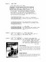
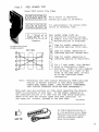
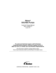
The First 10-Way
Additional advantages
of the SERIES E were
a simple alteration of
the payout percentage
by
changing
the
Personality Prom and
the capability of more
complex pays. Capitalizing on this latter
feature, the Model 1212
was one of the first
models introduced in
the new line. It was a 5line game that paid left
to right, making it the
first slot to pay 10
different ways. Proud of
this accomplishment,
Bally featured the
Model 1212 in a full
page color ad that
appeared in an 1980
issue of the Nevada
Magazine,
TUTORIAL
Getting Acquainted by Performing
the Eight Maintenance Tests
To gain a basic understanding of the electronic functions
and LED displays, it is advisable to read the introductory
pages, 3,4 & 5 before beginning the series of tests that
begin on page 6 and end on page (I8). Aiding in trouble
shooting, pages 20-23 explain the malfunction codes and page
26 has a chart of the malfunction codes that are displayed in the
LED display.
2
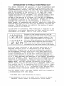
INTRODUCTION TO THE BALLY ELECTRONIC SLOT
This manual describes the operation of BALLY'S ELECTRONIC SLOT
MACHINE. You will find, in comparing this machine with the
electromechanical version, that the same basic functions and
timing relationships exist*. In fact, the only visible difference to the player is the addition of a 6 digit LED (Light
Emitting Diode)display**. This display, in addition to providing the function of InN METER, also performs several other
useful functions.
For example, a slot machine attendant,
called to the machine by a player, will be able to determine
by observing the code on the LED display, whether the machine
has detected a problem in its operation.
If there is a
problem, the code will tell the attendant if it is a coin jam,
empty hopper, or something more serious, requiring a technician
The code displayed will also help the technician localize the
problem. The LED display also permits the reading of meters
without entering the machine.
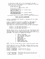
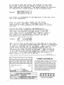
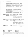
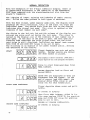
For the sake of discussion, when referring to examples of the
LED display, this manual describes the digit positions within
the display as columns 1 thru 6, from left to right.
2
:3
4
5
6
2
:3
4
5
6
[~[QTIE[
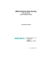
Examples of what might be observed in the LED
displays of the Series 1000 (small round windows) and
the Series 2000 (larger rectangular windows) . The
operation of the test procedures are very similar in
both series. When preforming a test on the Series 1000
use the same codes displayed as used on the Series
2000, except in cases where variations are noted by
the addition of the small round window LED displays.
Bally has taken advantage of the advanced technology of integrated circuits (IC's) to incorporate into the machine
reliability, flexibility, as well as bookkeeping, security,
and maintenance features which would have been impractical,
if not impossible, a few years ago. A microprocessor-based
system was determined to be the most effective approach to
achieve these desirable objectives. The MICROPROCESSOR (CPU)
is an IC that performs the functions of the central processing
unit of a computer. Thus, it controls the interpretation and
execution of instructions. These electrically coded instructions, called a PROGRA11, are stored in other IC's, called
MEMORY CHIPS. The CPU receives information in the form of
INPUTS, which tell the CPU the status of SNITCHES, REELS, ETC.
This enables the CPU to determine which OUTPUTS (coilS, lamps,
motors) should be on or off for the particular MODE of operation that the machine is in.
(ACCEPTING COINS, READING REELS,
DIS"ENSING COINS, DISPLAYING METERS, SELF-TESTING, ETC.)
The CPU, MEHORY CHIPS, and other CONTROL LOGIC are located on
a MICROPROCESSOR UNIT (MPU) BOARD.
*
**
See Reel Spin Time Variations on Page 24.
An exception to this is a model which contains a Replay
Register (Credi t ~leter) or Progressive ,Tac}:not Meter.
3
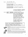
WHAT TO EXPECT WHEN POWER IS APPLIED
When power is applied, a brief self-test of vital functions
of the MPU board will-occur. During this self-test coins are
locked out.
After completion of this self-test, the slot
machine will return to some point in its normal operation.
This point is determined by what the machine was doing ,.;hen
power was turned off.
THE CENT:::R T'NO DECIMAL POINTS INDICATE
A RESET (PON'ER OFF, STATIC DISCHARGE, ETC.) OCCURRED SINCE THE
LAST HANDLE PULL.
The 6-DIGIT LED DISPLAY may appear as any of the 3 following
examples when power is turned on.
If the display exhibits
a severe flicker or takes a form other than those mentioned
below, see BUILT-IN TEST FUNCTIONS paragraph on following page.
1.
Machine was at some point in its normal operating sequence
when power was removed.
Example:
The number in the second column,
in this example 1, indicates one
coin was put into machine for
previous game and the 005 in the
fourth, fifth and sixth columns
indicates number of coins paid
out. (In this case 5 coins).
Example:
In this example 6 coins had been
played; 1000 coins had been paid
out.
fL[Jrnrnrnll
[ E
I.~~~
2.
The processor had detected a game malfunction prior to
pOIver being removed.
NOTE:
Examples of malfunction codes in this text are
those which correspond to the Bally Slot codes. On
some models, different codes are used. A cross reference
chart is provided for your convenience (page 28).
Example:
GTllrnrnfCl'sl
~~U!:::L~_l~
3.
The 31 in the first two columns
in this example indicate a particular malfunction. (In this
case a hopper jam.) The digits
in the last three columns indicate the number of coins paid
out before malfunction occurred.
The machine was in self-test #2 mode "hen power ,,,as turned
off.
Example:
~~[gIB.IB.@
4
If 8's are present in all six
columns for about one second,
the machine \d 11 energi ze each
lamp, coil and motor in a sequence
determined bv the features of
that particular machine.
[SEE TEST '2 IN SECTION III)
If Personality PROM (r17) is not installed in the MPU
Board, the following sequence will be observed on the display when pm,er is applied:
fLl,f-.
~ ~~
[[[t~_,*
Ib•Is.ILl/...:1.
I=r IL:..=, III
L!.:J
-
I/-/ICJICJ~CJICJ[/:JI
'-1. LI. U. U. U. 1..:1.
briefly, then
for 1 second, then
for 1 second, repeat.
(See "CAUTION" on Page 7)
*Irrelevant Data for AS-2978-5, 6 or 7; Blank for AS-2978-3.
BUILT-IN TEST FUNCTIONS
The BALLY ELECTRONIC SLOT MACHINE is equipped with two types
of test functions.
First, a diagnostic self-test on POWER UP. This test is
primarily used to localize a problem in the MPU BOARD.
These particular problems are discussed in detail in
"MPU BOARD TEST STATION OPERATORS GUIDE AND TEST PROCEDURES":
FO-650-l for MPU Board #AS-2978-3
FO-650-3 for MPU Board #AS-2978-5 or -6
FO-650-11 for MPU Board #AS-2978-7
Second, manual tests. All manual tests are initiated by uSing
the TEST button on the hopper control board. The number of
times the TEST button is pressed determines which test will be
performed. The tests are numbered as follows:
1.
2.
3.
4.
5.
6.
7.
8.
NOTE:
START OF NEW GAME
COIL AND LAMP (LOAD) TEST
(See "CAUTION" on Page 7)
SWITCH TEST
HOPPER TEST
REEL READER TEST
PROGRAM TEST
METER DISPLAY TEST
GAME FUNCTIONAL TEST
The Door Slvitch must be open to enter any manual test.
Closing the door while in TEST MODE, (decimal points in display) terminates the test in progress, indexes the reels and
causes the display to read:
ClOSing the door has no
effect if M7 is removed.
On the Series 1000, closing the door while in the
TEST MODE (decimal points in display) shows
this display,
5
INITIAL SET-UP (MAINTENANCE TESTS)
Performing the following procedure will assure the operator
that the machine is operating properly before putting i t
out on location. If any problem is encountered while testing the machine, the entire procedure should be repeated.
This will assure the operator that some previously tested
part has not been affected while correcting another problem.
"START
Step 1.
of
NEW GAME"
vii th the door open, turn the power swi tch ON.
Near the front of the HOPPER unit is a printed
circuit board with two push button switches located at the top. These switches are labeled
RESET (left) and TEST (right). Press the TEST
button ONE Tll1E ONLY, while observing the digital
disnla v •
[[[ff[]
*For
For
not
was
",hile button is depressed
MPU Board AS-2978-3, these digits are blank.
MPU Boards AS-2879-5, 6 & 7, these digits do
change from what was showing before the button
depressed.
r--l[g[Q[]
O.
nnnn
U. U. U. '-I.
I
I.
~or approximately one second
after button is released, then
. . .
~enains
until some action is
ta::en such as closing door and
~laying machine, pressing TEST
button, pressing RESET button, etc.
The DOOR OPEN lamp (in tower)
switch is open. COIN LOCKOUT
machine is in any test mode.
is lit whenever power is on.
any self-test terminates it.
HOT TIP
6
(!!!!!!!H~
is lit whenever door
is in effect while the
General illumination
ClOSing door while in
test continues
The wafer connectors on the boards are
designated as "J" connections. A blackened
area on a wafer, usually indicates a bad or
dirty connection. This problem can be
remedied by cleaning the offending point.
Step 2.
LOAD TEST
Press TEST button two times.
CAUTION: DO NOT perform this test without
personality PROM (1-17) installed, as this
would cause the hopper fuse to blow.
In this test, one OUTPUT(or LOADJis energized
each second. Closing the coin switch while in
this test causes the CPU to stop sequencing,
continuously energizing the LOAD that was active
when the switch was closed.
fnTrirnrnrnG
While button is depressed
(Zeroes are blank on AS-2978-3)
,_ .I
\" IU.
n U.
I I 1-1.
I I IU.
I I l.:r
For approximately one second
after button is released, then
~~t:=~~B
-I.
1. (LED TEST)
Lit along with reel reader lamps
for approximately one second,
then . . •
Example'
2. (TILT lamp test)
Lit along with TILT lamp for
one second, then • . •
Example:
3. (DEPOSIT COIN lamp test)
Lit along with DEPOSIT COIN lamp
for one second, then continues
in this manner energizing each
lamp and coil (except hopper motor
and displaying associated code.
test continues
TEST SWITCH
Located on the Hopper Board, the push button TEST SWITCH,
in conjunction with the LED display, is used to perform the
Maintenance Tests described on pages 6-17. The six digit LED
display is mounted on the front door at the right of the reel
window.
RESET SWITCH
The game Reset Switch is located on the Hopper Board at the
top right hand corner. Pushing this reset button often restarts
the machine after there has been a minor malfunction.
7
At the end of each test cycle, the contents of the "LOAD
TEST lclETER" indicating the number of times this test has
been performed are displayed. The meter reading is displayed
for approxinately three Seconds in the following format:
inrnrn luTLiill
Example-
~1'::!.:~L2:L':~
This meter is incremented at the beginning of the test cycle
and is not resettable.
After all loads have been tested, the CPU begins
again at step 1 (LED test), continuing until test is
terminated by either pressing the TEST button or closing
the noor.
Turning off power or pressing the RESET button
while in this test causes the CPU to return to step 1
(LED test) and continue from that point. After the
first step, the CPU is programmed to display a code as
each output load i3 energized. This code is used by
the technician to determine which circuit the CPU is
acti vatinrr I
Example:
and ta:t::es
t~v~
.f=nr", ~
\2[[~B[~~[gJ
The 2 in the first column shOt;s thi't the game is in test mode
#2. The 1 in the third column shows that the CPU is addressing
IO Board #1 (standard IO for all games). The 4 in the fourth
column sholtIS that the CPU is addressing OUTPUT PORT #4.
The 20 in L~e fifth and sixth columns shows that the CPU is
activating the sixth circuit of the PORT.
(PORT is defined
to be a device which ;::>rovides electrical access to a system
or circuit. This system uses PORTS with six circuits or
BITS, coded 01, 02, 04, 08, 10 and 20.)
test continues
UJ
Ul
U3
U,
U5
U6
[iJ
--' [5J' ~I
_. ~I
_. ~'
_. ~'
-'
111
1111/1111
--
o
0°0000000
JI
00000000
M 645-608
FRONT
P2948-473
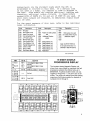
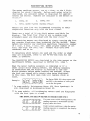
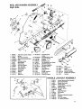
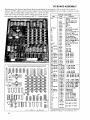
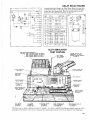
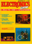
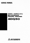
6·DIGET LED DISPLAY
The Display Board is located on the front door
to the right of the reel window (see p. 60).
Not only is it used for the test functions, but
also to record the coins paid out and locate a
machine malfunction. The rectangle display
shown to the left is used on the 2000 Series.
The one below, using small round windows,
was utilized on the 1000 series.
AS-2985-2 DISPLAY BOARD ASSEMBLY
SYMBOL PART NO.
DESCRIPTION
Jl
16 CONNECTOR FLAT CABLE -INSTALLED
Ul-U6
E·680-11 LINTRON!X HD-I077R, 7 SEG, DISPLAY
8
1000 Series Led Display
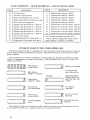
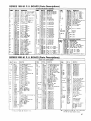
Listed below are the standard loads which the CPU is
programmed to activate in this test.
If a certain load
is not used in a model, its address or code is skipped in
the test.
Some models may require additional lighting and,
therefore, additional output circuits.
In these models
unused BITS of PORTS #3, #4 and all of PORT #5 are used. If
still more outputs are required, an additional output board
will be used.
For the exact sequence of this test, refer to the individual
model information.
Code
Description
Code
1101
1102
1104
1108
1110
1120
1201
1202
1204
1208
1210
1220
Tilt Lamp
Door Open Lamp
Insert Coin Lamp
Coin Accepted Lamp
J.P. Tower Lamp
Winner Paid Lamp
Coin Lockout Coil
Coin Deflector Coil
Handle Release Coil
Chime or Bell
Gong or Bell
Door Alarm Buzzer
1301
1302
1304
1308
1310
1340
1401
1402
1404
1408
1410
1420
Code
Description
Payline or Odds Lamps
and
Additional Feature
Lamps
Reel Solenoid
Reel Solenoid
Reel Solenoid
Reel Solenoid
Reel Solenoid
Reel Motor
#1
#2
#3
#4
#5
1501
1502
1504
1508
1510
1520
Description
1500 series only used
on models which require
additional outputs
Note: OUTPUT PORT #0
is not used in this test. It is
checked in tests #4 and #5.
test continues
SlIIOL
II Tn" 87
08
DB Tn" 015
016
II J2
II Tnru lID
81 Tn" liD
CI Tn" tiD
All Tbru ABO
811 Tnru 880
ell Tnru tiD
Pili '0.
£4131-1
-
£-137-1
-
£-771-11
E-587-1~
l£stRIPTilI
ElectfG-tacnatic • • tic Display
f.t Ised
Ulctr.--lalnetic ••eric Display
lot Used
1l~IGO
P.C. Connector - lottn Entry
Itot Used
Diode lIW48
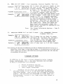
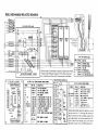
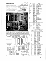
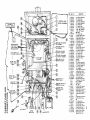
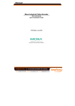
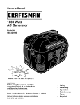
14 DIGET DOUBLE
PROGRESSIVE DISPLAY
The fourteen electro-Magnetic Display unit,
shown here, was utilized on machines that had
progressive jackpots that offered wins up to
$99,999.99. A optional sixteen meter unit was
capable of mega-wins- one penny shy of ten
million. The single unit below shows the lighting
sequences that make possible the displays of
numbers from 0 through 9.
ISIBISlsisisial
I
s.
or,..!
O.
COM.
9
Step 3.
SWITCH TEST
Press TEST button three times.
Example:
[[[[[~
While button is depressed
-I rn II II rnT:Jl
f[l
~~ '-,. 1..J·~0
For approximately one second after
button is released, then . .
~[[[[D
Until test is aborted or a switch
is closed (a normally closed switch
must be opened first)
s[[m-mlll
While coin switch held closed
L=: .
Example:
~~
5[irnrnGl
~ .~~t=:J
While hopper roller arm at rest
(after lifting it once), until
some other switch is actuated.
Switches not included in test:
Power Switch, Door Switch,
Change Button Switch, TEST, RESET
switches, Coin Return Switch on
"IKE" Dollar Machines. For the
code associated with each switch,
see individual model information.
test continues
The COIN SWITCH is located
on the inside of the Front
Door immediately below
the Coin Acceptor.
./'_=~iY/
The LEVEL SWITCH
is located at the
base of the
Hopper..
The OPTO HOPPER
SWITCH is located
above the Hopper Pin
Wheel. On later models. the
Opto Switch was replaced by
a Micro Switch.
The DOOR SWITCH is located
behind. and actuated by. the lower
Door Hinge.
10
The ARM SWITCH. above the Cam. and
the KICK SWITCH are located on the left
Side Plate Assembly of the Mechanism.
INPUT CODE ASSIGNMENTS
See individual model information for additional switches.
CODE
DESCRIPTION
001
002
Coin Switch
Hopper Switch
Level Switch
Door S\<Ti tell (Hinge, Cam Series Comb
Kick Switch (Reel 11ech)
Arm Switch (Reel Hech)
"()~
*008
010
1)2'1
*Not displayed with personality PROM installed. Door switch closure
terminates test.
Input Port #1 contains the reel reader inputs and normally closed
coin switch input.
This input (code 120) will be observed after
SLOWLY releasing the coin switch. The reel reader inputs are test
in sten #5.
Input Ports #2 thru il4 are sr.are inputs for Most models,
except Bit 116 of Port 2 (Code 220) is used for the key switch.
'J:he DIP Svli tches on the MPU Board are treated in a slightly
different manner. They are read directly by the microprocessor
chip, not thru an input port on the I.O. Board. The DIP switches
are coded as follows:
CODE
DESCRIPTION
501
502
504
508
510
520
Not Used
Special Function
Switch
Switch
S,vitch
Switch
Switch
Switch
Switch
Switch
#1
#2
#3
#4
#5
#6
#7
118
To determine the functions of the dip switches, see STANDARD
OPTIONS section of this r,lanual.
test continues
AN ESSENTIAL TOOL FOR BASIC REPAIRS
The Voltmeter (Multi tester) is a musl for working on SERIES E
machines. Used as a continuity tester, it is useful for tracing
circuits, localing bad soldering joints and for checking wires and
Flat Cables for breaks. Using the voltage function, the meter is
necessary for checking the voltage on the boards and in various
circuitry.
An inexpensive model may be purchased for as low as $20.
For difficult repairs consult your dealer,
11
Step 4.
HOPPER TEST (10 Coin
pay)
Press TEST button four times.
rrilfl-' rnrnrnrLil
~l=:~l:-!:~~
;lhile button is depressed
(Zeroes are blank on AS-297S-3)
For approximately one second after
button is released, then . •
fW[iTnTnTi=il
l2
.~~~
Until coins begin to pass under
roller, at which time the win meter
begins to increment, 001, 002, 003,
etc.
When payout is complete (Hopper
Motor stops). At this time, the
winner paid lamp is lit.
If the processor detects a malfunction during this
test, the hopper motor is stopped, feature lamps are
flashed, the TILT lamp is lit and a code indicating
the type of malfunction is flashed alternately with
"coins in last game" (when in test mode, "coins in
last game" is set to zero). The malfunction codes
possible in this test are:
30
31
32
Hopper Override
Hopper Jam
Hopper Empty
33
Reset During Payout (Used on Series 1000 Only)
If po,,,er is turned off to service a malfunction, the
test will be terminated when power is turned back on.
If it is not necessary to turn off power, the RESET
button may be used to terminate this test. tes t con t.mues
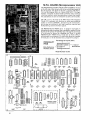
HOPPER BOARDS
The Series 1000 used the
board on the left. The one
on the right is for the Series
2000. The boards are
interchangeable by a minor
one wire change that
relocates the 120 VAC line.
To use a 2000 Series board in
a 1000, the no. 9 wire is
moved to the 8 pin. To use a
1000 Series board in a 2000,
the 8 wire is moved to the 9
pin. For more Hopper Board
information see page 47.
12
Step 5.
REEL READER TEST
Press TEST button five times.
fnrnrnrnrnr2l
~~~~~~
While button is depressed
(Zeroes are blank on AS-2978-3)
I,-,\n
n n[nfCl
ILl. I_I. Lt. l...l. '-1.0
For approximately one second after
button is released, then . .
r-J~'r:Jf,LJ~~
~E~L!:LU
Example:
For additional Position Reader
information see page 46.
PAYLINES
~
rt>ot-""-.:::+--t---+--+~j.O
CV01--+--t:~--r----to
!Vo+:::>-",,+-+---f---f.::::.....:-+o
lV
Note:
Reel reader lamps light up.
Payline-For mul~iple. ,?ayline.
, models, hold COln sWltch untll
., desired pay line is displayed.
I II
[--I
LL.
Code for symbol appearing on
indicated payline, first reel.
Code for symbol appearing on
indicated payline, second reel.
Code for symbol appearing on
indicated payline of third reel.
For a 3 reel model, only decimal
point is displayed in thes~
positions. Codes for reel symbols
will be found on a label on the
front of the reel mech, as well
as in the individual model
information.
Performing this test without Personality PROM installed
results in decimal position of reel being displayed
rather than symbol codes.
(See FO-650-2: "PERIPHERAL
TEST STATION OPERATORS GUIDE AND TEST PROCEDURES' \ •
Move each reel one position at a time while observing the display.
Check all positions on each reel. If the symbol appearing on
the indicated payline is at odds with the code being displayed,
check to be sure the correct tapes have been installed. If
the tapes are correct, proceed to the next test.
test continues
HOT TIP
As with all electronic devices. it
is a very good idea to use a Surge
Protector to prevent the sensitive
electronic components against
house current surges.
13
Step
6.
MEMORY CHECK
This test checks program memory and displays the
"personality PROM" identification number, (which
is listed on the Special Model Information Form)
if the test is positive. This test is also performed each time the processor returns from reset
or "power down". For the possible error conditions
see section titled "POWER UP MALFUNCTION CODES".
Press TEST button six times.
!"lfl!fllrllfl!b!
LI. U. U. U.'.J.I .
~lliile
button is depressed.
(Zeroes are blank on AS-2978-3)
11,lrll"I"I"\br
For approximately one second after
J.IU. U. U. L'. I • button is released, then . • •
Example:
rofjjlnn IITo91-il
~~~~~
Personality PROM I.D.
is displayed.
N~ber
Until test is terminated by
pressing RESET, TEST or Door
Switch.
Example:
rsrc;fLI[[rIl
L:::.:.~l2: . .L!:l
If no Personality PROM installed,
ROM information is displayed
instead.
The 5 6 4 indicates program version
(in this example, version 5.64).
The 1 indicates "on-line" (SDS)
version.
This position is blank
for "off-line" version.
If no Personality PROM installed on the Series
1000, ROM information is displayed instead
Example:
test continues
PERSONALITY
PROM
541 089 5/20/83 (
E-2238-14
I
HOT TIP
The payout percentage of a slot machine may be verified by pressing the Test Button a total of six times. It may
also be confirmed, along with the model number of the machine. by checking the numbers on the Personality
Prom located on the M.P.D. Board (see page 56).
14
Step
MAINTENANCE METER OISPLAY TEST
7.
The Bally slot is equipped with a set of four meters
intended to enhance the operator's maintenance program.
These meters, numbered 17 through 20, monitor:
17.
RESET METER
The number of times the processor has been caused
to reset.
IS.
MALFUNCTION
METER
The number of malfunctions sensed by the processor.
19.
LOAD TEST
METER
The number of times that TEST #2 has been performed.
20.
DOOR OPENED
METER
The number of times the door has been opened.
To implement this test, press test button seven times.
rnrnrnrnrnl-il
~~~~~L!:I
rr-,In
rn I-ll
While button is depressed
(Zeroes are blank on AS-297S-3)
II II
~~ L/. I...J.~~
For approximately one second aft.
button is released, then . .
CCCCU[iJ
For one second,
For one second, maintenance meter
number 1.
lnInr.=lr-l
Example:
lo·~tQlf!iJlb.1
For six seconds, value in RESET
METER (counts number of times
processor has gone into reset
condition. MPU board circuitry
forces the processor to reset tc
prevent erratic operation which
might be caused by static electric
or power fluctuations).
test continues
A BLOWN FUSE AND TROUBLESHOOTING
HOT TIP
A blown fuse, in conjunction with the P. C. Board schematics (pages 50, 51) and the
fuse box diagram (page 63) can aid in isolating the circuit that caused the failure.
J
'
HOPPER FUSE WARNING LIGHT
A red lamp on the hopper lights when the fuse is blown. Replace it with a 5
amp 3AG fuse. If it blows a second time, check the Hopper components
15
[[[[[l~
Example:
[Q " r11"lr'\' 'I
U. L/. U. LI.
I.
[[[CO[§]
:;xample:
nnn8~[]
u.
LI. LI.
Example:
I.
I.
I.
For one second,
For six seconds, value in MALFUNC'tION
METER (counts number of times game
malfunctions have caused machine
to tilt).
For one second,
For six seconds, value in LOAD
TEST METER.
(Counts number of
times self-test #2 has been
performed) .
[[[[~[QJ
For one second,
lolnlrllnl-'[]
For six seconds, value in DOOR
OPENED METER.
(Counts number
of times door has been opened).
. L/. Lt. LI' C.
t.
[~Jo[ralolol
Until some action is taken.
Maintenance meter display routine
has been completed and machine
is conditioned for the start
of the next game.
TO CONTINUE SERIES 1000 TESTS OMIT THE ABOVE AND CONTINUE WITH THE STEPS BELOW
(~=::
;:;: ;fr;;
For one second, maintenance meter number 2.
For six seconds, value in ,MALFUNCTION METER
(counts number of times game malfunctions have
caused machine to tilt).
,\7 \7 ~
3 For one second, maintenance meter number 3:
\:.. .% \. .;; '> ./ \. .;; \. .1 \ :?I
f?' "\7 V
i'
Example:
V
@/jL=a;:a::i!:~7}
( ~: :: :=====©
For six seconds, value in DOOR OPENED METER.
(counts number of times door has been opened.
For one second, maintenance number 4:
For Six seconds, value in LOAD TEST METER.
(counts number of times self-test #2 has been
preformed).
Until some action is taken. Maintenance meter
display routine has been completed and machine is
conditioned for the start of the next game.
16
GAME FUNCTIONAL TEST
Step 8.
l'ress ':'EST button eight times.
n,-,nnn
-§}I
\U. lQ~[Q
U. U. U.\'
I" \n
I
I.
B.
vfuile button is depressed
(teroes are blank on AS-2978-3)
8\
II II II \
For approximately one second
-I. U. LI. 1-1. LI. I • after button is released, then . • •
If Personality PROM (H7) is NOT installed, the display will fa~into
the sequence described on page 5.
Example:
8 indicates Test #8 mode.
raGlfQlrin Inl machine
2 is current coins in. The slot
is in the game function
~EL:~t=!:J
test, allowing normal operation
except the reels may be set up
for testing and any payout
that occurs is displayed in
the win meter but is not paid
by the hopper and the winner
paid lamp is not lit. Also, to
simplify testing, the coin switch
malfunction (See Page 27) is bypassed while in this test.
The game will remain in this
test mode (decimal points
on display) until it is terminated by a door switch or
test button closure.
At this ,"oint all electronic functions have been
tested. After performing routine mechanical inspection (slug rejection, proper lubrication of
mechanical assemblies, proper reel kick anr. spin, etc.),
the machine is ready to be placed on location.
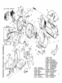
BEAUPLUG Beauplugs are the electric wire connectors that allow the Reel Mechanism
(used only on the early Series 1000 slots, and the Hopper to be removed from the cabinet. To
prevent damage to the Beauplugs remove these units carefully,
HOT TIP If there is a broken point on a Beauplug, Molex Connector or an Amp Plug,
move the wire that is connected to the broken point to an unused point -
if available.
AMP PLUGS They are similar in construction and repair to the Molex Connectors (page
36). Due to their ability to conduct low voltage circuits, Amp Plugs replaced the Beauplugs on
the mechanisms on later Series 1000 and on all Series 2000 slots. These connectors are located
in pairs on the rear side frame. New Beauplugs, Molex Connectors and Amp Plugs, along with
the necessary tools, may be purchased from the Wico Corporation (see page 63).
17
NORMAL OPERATION
With the exception of the 6-digit numerical display, there is
no appreciable difference in the operation of the ELECTRONIC
SLOT when compared with the electromechanical slot from the
player's viewpoint.
The lighting of lamps, spinning and indexing of reels, payout,
etc., follow the same pattern in both types of machines.
With the door closed, under regular game play, the display board
presents two vital statistics, total in and total out count per
individual game. The second digit from the left on the display
indicates coin played last game. This count is updated at the
indexing of reel number one each game*.
The digits in the 3rd, 4th, 5th and 6th columns of the display constitute the coins paid out during the last game. This count is
zeroed on the display also at the indexing of reel number one of
each game.
If the door of the game is open, the door open malfunction code overrides the coins played count, but the coins
paid value is still displayed. Performing any manual test causes
both COIN IN and COIN OUT values to be set to zero.
The follo\"ing is an example of two games (handle pulls), showing
the operation of the display.
Player deposits one coin and pulls
handle.
Decimal points are turned
off when handle is pulled.
START
( ~:P=::fL:D:~D)
This display is shown on Series 1,000 after a
player deposits one coin and pulls the handle.
[[Z[[Q[Q(gJ
Coins in count displayed when first
REEL indexes.
Assume cherries land on first and
second REELS.
COINS OUT are displayed as they are
dispensed from the hopper. At the
end of payout (and this game), the
display shows TOTAL coins in and
coins out for this handle pull.
FIRST GAHE COMPLETED
Player deposits three coins and pulls
handle.
[[IOO!o[sl
[[QI[Q-I
[Q]n
[[E
-_I
-
L/. L..I U
SECOND GAl'lE COHPLE'rED
iG[-rninrnl
i _~ J~L'='_~
18
:~o
change in display.
first REEL indexes, COINS IN for
this game replace COINS IN for previous
game and COINS OUT value for previous
game is set to zero.
Assume no tvinning comb ina tion.
~vhen
NO CHANGE in display.
BOOKKEEPING METERS
The meter readings appear, one at a time, on the 6 digit
display for about 6 seconds. Before each meter value is
displayed, its assigned number is displayed for approximately one second. Numbers are assigned to the meters as
follo".:~-:;'{
:
2.
1.
TOTAL IN
1•
TOTl\.L GAHES PLAYED
TOTAL OUT
3.
CASH BOX
(HANDLE PULLS)
Meters one thru four are incremented according to their
respective functions only with the door closed.
There are a total of 16 six digit meters available for
display. The first four (five or six on models with
attendant pays) are displayed with the door close(:.*j,.
The remaining meters are displayed by simply turning the door
key counter clock-wise then actuating the key switch. These
meters may monitor any condition specified, typically; number
of 1 coin, 2 coin, 3 coin, etc. games played; number of 1st
coin, 2nd coin, 3rd coin, etc. Jackpot wins that have
occurred; and so on.
To determine which meters are used and the order in wh~ch
they are displayed, refer to the FO-6S2-XXX form for the
model in question.
The BOOKEEPING METERS are displayed in the sa~e manner as the
HAINTENANCE METERS, described in SECTION III, step 7.
When the meter reading sequence is completed or if a
reset occurs while reading meters, the reading sequence
is terminated and the display is restored to the condition present before meter reading was started, unless
the door was opened while meters were being displayed.
In this case, the door open code will replace coins in
count.
On Series 2000, 50 is door open code
Example.
and 005 is the number of coins paid
out in the last game.
;, In some models, Maintenance Meter #20 (Door Openings) is
also displayed as Bookkeeping Meter #0.
**
In some models, all bookkeeping meters used are displayed
with the door open or closed.
THE DISPLAYS BELOW REFER TO SERIES 1000 ONLY
If a reset occurs while reading meters, the
reading sequence is terminated and the
display takes this form.
Under normal conditions, when the meter
reading sequence is completed, the display
takes this form.
19
GAME CONDITION MALFUNCTION CODES
In the course of normal machine operation, the CPU is continuously monitoring conditions by sensing the INPUTS and comparing
them with what the PROGRAM says they should be.
If the CPU detects a difference, it checks the PROGRAM to find
out what to do next. Depending upon which INPUT is at fault,
the PROGRN1 instructs the CPU to take one or more of the
following actions:
1. Display a MALFUNCTION CODE
(Excepting the Door Open code (50),
all malfunction codes are flashed alternately with
COINS IN i nforma tion.)
2. Suspend play
3. Flash feature lamps
4. Light the TILT lamp
These actions are terminated by correcting the malfunction and
pressing the RESET button.
Note:
The TEST button is disabled while the machine is in the
TILT mode to prevent disruption of a game in progress.
The following is an explanation of the standard MALFUNCTION CODES used:
1.
COIN IN JAM - Play suspended, feature flashed, TILT lit.
-'I/DQ-' fli ul
Example: \,_
LI
1...1
I
I .,
__ L_
Flashing alternately with:
Example:
[1,~[Jol7l/-/!
Example:
is mni mill wi
The 2 equals coins in for current game.
Clearing the jam and pressing the RESET
switch causes the feature lites to stop
flashing.
Door may now be closed and play resumed.
Note: Any time the door is opened, the
Display shows door open code. To see a
malfunction code, actuate the KEY switch.
Any time the RESET button is pressed, the center
two decimal points are lit.
~~~I
Note:
2.
The 20 indicates a jam on the COIN SWITCH.
The 014 equals coins paid out in previous
game.
HOPPER OVERRIDE - Play suspended, feature flashed, TILT lit.
Example:
13[Q[\nlo lb I
Flashing alternately with:
~I
ExamPle:[i
L
f,[nTLl
The 30 indicates that too many coins
were dispensed by the hopper.
006 equals number of coins paid out
for this pull of the handle.
UI_/~ 2 indicates coins played for current game.
The 2 does not appear on Series 1000
Although the occurrence of this malfunction is unlikely, the
possibility that it may happen does exist and will be detected
by the machine. The fact that it requires a service call
allows the technician to determine the cause (most likely
mechanical in nature) and prevent it from recurring.
Press
RESET button to start next game.
20
3.
aOPPER ,TAM - Play suspended, feature flashed, TILT lit.
Example:
[-':,1
-il
-r~-'-"in ~
1..1 I I
1..1 ,LI:l
L_.L
. _____
'-_
Flashing alternately with
Example:
r--l'C::J1r--U"!
rt [-'II
LJ:LI =,
IL_
.___ l____ .'- __...J
I
The 2 is the number of
coins in for the current
game. It doesn't appear
in the Series 1000.
4.
Indicates a coin is stuck under the
roller. To complete payout, clear jam
and press the R~SET button. The door
must remain open until the TILT lamp
lites, then goes out again (approx.l sec.),
after which the operator has 3 secs. tn
close the door before payout resumes.
Appropriate feature lites are lit before
payout is completed.
HOPPER EMPTY - Play suspended, feature flashed, TILT lit.
Zxample:
i3 f;?[--IO!i5\
3\
I_L_
,-_L_ ___
Flashing alternately with:
Example:
r-T5[lgrii
rii -'II
Ie
LIlLI' =',
_ L .. _
5.
31 is the malfunction code.
003 is the number of coins paid out.
Indicates that the specified time
limit has elapsed without a coin being
detected. After de terming and
correcting the cause, follow the same
procedure as described above to complete
payout.
_L-L:'.J
RESET DURING PAYOUT - Play suspended, TILT lit.
Flashing alternately with:
Example:
r- '--E[-[Q[rt~IL - t.:
LlILI-'
_
This code appears when a reset occurs
during payout.
This can be caused by
momentary power interruption, low
line voltage, or static interference,
any of which could cause the microprocessor to perform a faulty execution
of program instructions. Entering the
TILT mode prevents potentially disastrous results.
To complete the payout, follow the pro-·
cenure oescribed above for HODn>:" "MI.
6. REEL HELD OR CANNOT BE READ - Play suspended, feature flashed, TILT lit.
2xam?le:
iwif-[lnf
r'[cl
L2L LlIL/B
Flashed alternately with:
The 41 means the position reader on the
1st REEL has sensed one of the following
(A) No motion, (B) 3 positional errors during this spin. 42 means the 2nd REEL is
at fault; 43 means the 3rd REEL; 44 the
4th REEL and 45 the 5th REEL. The reels
are numbered 1 thru 5, from left to right.
Sxample:
The 2 is the number
of coins played for
this handle pull.
Note:
005 is the number of coins paid out in
previous game. After determining and
correcting the cause, spin by hand any
non-indexed reels, press the RESET
button and close the door to complete
the game in progress.
If necessary,
the game may be terminated by pressing
the TEST button one time.
See Part 3 of standard options on Page 24.
21
7.
DOOR OPEN -
5 second BUZZER alarm, Door Open Lamp (in tower)
The 50 indicates the DOOR has been
opened.
Example:
Example:
lit.
iT""'?
";;7 "" I
":7
"r ""
~ JJ}.!\. /P/,,,D/P.iJ
If the door is closed on
the Series I 000 while in
MANUAL TEST mode,
the display takes on the
above display form.
The DOOR OPEN lamp stays lit for as
long as the door is open. Closing the
door while in this state does not disturb the display.
The 50 is replaced
by the number of coins in for previous
game when the handle is pulled.
Door opening is detected by the
hinge switch or the lock cam switch.
These switches are wired in series.
The BUZZER ALARM is activated for 5
seconds every minute while the door is
open except during the time in which
the machine is in a manual TEST mode.
Feature lamps flashing while this code is
present means that some other malfunction
has occurred. The KEY switch may be
actuated to display the other malfunction
information for as long as the KEY switch
is held.
8.
HANDLE PULLED WITH NO COINS IN
Example:
1-7TnirnroGl
~~~~
Flashed alternately with:
Example:
9.
[[Q[[QfOlc'\
Play suspended, feature flashed,
TILT lit.
The 70 indicates there is a malfunction
in the handle mechanism allowing the
handle to be pulled with no coins played.
Reels are not indexed because most causes
of this condition are mechanical and,
therefore, repetitive in nature.
The 0 indicates no coins have been played.
The 002 is the number of coins paid out
last game.
ILLEGAL PLAY - DOOR OPEN Play suspended, feature flashed, TILT lit.
(KEY swi tch mus t be actuated t.o see thi s code)
Example:
Ii 10-[-\1J [0 [Dl
Flashed alternately with:
Example:
[~[lQlD[gJ
Note:
22
The 70 indicates play has been attempted
with the door open after Reel #1 indexed;
000, no coins paid out.
3 is the number of coins played for this
game.
This malfunction is sensed only wr.en a jumper is installed
from ground to J2, Pin 8 of I/O Board. (See Page 27 Item D)
10.
REEL DID NOT INDEX - Play suspended, feature flashed, TILT lit.
Example:
l['[IDQ'"!_, I i
I
II
/.J II I.J
I
__
__1_-
Flashed alternately with:
Example:
[Q1'
[~[[Q1i
rt
C
UL.ILI
-
-
Note:
11.
The 71 means the position reader on the
1st reel is not able to obtain a consistent reading.
72 means 2nd reel is
at fault; 73, 3rd reel; 74, 4th reel;
75, 5th reel.
If the reel in question
is' properly indexed, then this tilt
indicates the reel has been moved since
it was indexed.
(This test is not performed in SOS (-1) program versions.)
If the reel is not indexed, the cause
for this malfunction is most likely
mechanical.
Self-test #2 (see page 7)
may be used to verify the operation of
the index coil.
After the cause has
been found and corrected, press the
RESET button followed by depressing the
TEST button once.
See Jumper Selectable Options - Item D,
on page 27.
POSITION ERRORS IN 2 OF LAST 8 SPINS - Play suspended, feature
flashed, TILT lit.
Example:
~[IDQ'
,
I
/.J
-
[Q'
~.:
'_'
_I
Flashing alternately with:
Example:
IT'L[Q[Q~
The 91 means the 1st Reel; 92 means
2nd Reel; 93, 3rd Reel; 94, 4th Reel;
95, 5th Reel.
This tilt indica~
that during the last 8 games there
was a positional error during the
spin of that reel in 2 of the 8 games.
Note: Displays for the previous Malfunction Codes (8. Handle Pulled With No Coins In, 9.
Illegal Play-Door Open, 10. Reel Did Not Index, II. Position Errors in 2 of the Last 8
Spins) appear also on Series 1000 LEOS that use Program Proms (MI, M2, M3) that
are numbered 564 and above.
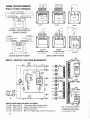
STANDARD OPTIONS
In addition to the usual options offered by Bally (custom
glass, percentages, eto.), two more features are included
in Bally's Electronic Slot Hachine.
1.
:?~
3.
1.
SHi tch selectable options.
external connections.
Cable Jumper Selections.
O~ticnal
Standard options which are selected by setting
switches either to ON or to OFF have been incorporated
into this system.
Hore options are included in certain
models.
The switches are contained in a DIP (Dual InLine Package) located in the lower right hand corner of
the MPU Board.
23
SALL POINT PEN OR
SIMILAR PROSE MAY
BE USED TO SET
SWITCHES
Sill TCH
NO.
OFF
ON
Jackpot Be II
(continuous signal)
I
Jackpot Gong
(pulsed signal)
2
3
4
5
6
See Individual
Model Information
DIP
SWITCHES
No t used
7
Must be ON in
game ope ra t ion
8
2.
Only when troubleshooting MPU Board.
A terminal block is provided ,'lith the following standard
connections:
Typical Circuit Connections
Terminal Block is
located on the back
wall of the cabinet
behind the Hopper.
80
GROUND
70
50V.A.C.
20
7.5V.A.C.
TO
EXTERNAL
71
LAMP
72
DOOR OPEN LAM P
68
J.P. TOwER LAMP
CIRCUITS
Where a lamp is used in the machine, any external device
connected to that the corresponding wire MUST be a 6 volt
device.
Additional connections can be supplied upon request to meet
your special requirements.
For any additions or exceptions to the above diagram, see
the GAME I'IIRING DIAGRI\~1 & PLUG ~!IRING I:-JFO supplied with
each machine.
3.
JUMPER SELECTABLE OPTIONS
A)
24
TILT CODE SELECT
,'lith a jumper installed from J3, Pin 20 of the I/O
Board to ground (Jl, Pin 28), the Bally Slot Halfunction
Codes are used. With this jumper removed, the SDS
malfunction exception codes are used. (See Page 26 )
B)
SPIN CONTROL SELECT
With a jumper installed from J3, Pin 16 of the I/O
Board to ground (J3, Pin 7) , current game is nullified
upon pressing the RESET button while a 4X malfunction
is present.
c)
REEL SPIN TIME VARIATIONS
In some locations it is desirable for the reels to spin
for a shorter or longer period of time than that set at
the factory.
To allow for this flexibility, three
diodes may be installed on the Reel Reader Control
Board. By installing one or more of these diodes
various timing combinations may be obtained as described
below.
DIODE
INSTALLED
NO
fUNCTION
DIODE
Long
CRI
CR2 & 3
Med. Long
CR2
CRa
long
CR3
CR2
Med. Short
CR2 & 3
Sho r t
~---""
LACE ELECTRICAL
Max.Variation
Time of
All Reels
Shor t
CRI
END OF DIODE
WITH STRIPE
WHAT IS
AffECTED
*
TAPE UNDER DIODES
Spin Time
of
Ree I #1
*
* Long for Atlantic Ci ty Models
All Diodes are lN4148 Type
Bally PIN E-587-014
Back Side of AS-2983-1 Reel Reader
Control Board
Machines produced after December, 1982 are equipped with
Dip Switches on the Reel Reader Control Board (AS-2983-2)
to provide these functions.
By setting these switches, various timing combinations
may be obtained as described below:
SWITCH NO.
ON
OFf
---
1
1
2 &
FUNCTION
Sho r t
1------Long
Note:
Variation
(a II Reels)
Me d. Long
-- - 1-----3 ------long
2
3
--- - -- ------lied. Short
2
3
--1-------
2 & 3
Max.
Spin Time
(Reel # 1)
Shu r t
Svd tches # 4 thru # 8 are reserved for future use.
25
GAME CONDITION -
QUICK REFERENCE -
DESCRIPTION
CODE
Coin switch jam
Too many coins dispensed
Hopper jam (Roller arm up too long)
Hopper empty (Roller arm down too long)
Reset occurred during payout
Improper spin (Reel held, etc,) - Reel #1
Improper spin (Reel held, etc,) - Reel #2
Improper spin (Reel held, etc,) - Reel #3
Improper spin (Reel held, etc.) - Reel #4
Improper spin (Reel held, etc.) - Reel #5
Door has been opened
Illegal handle pull (No coins played) ; 'or
Illegal game (Coins played, door open)*
20
30
31
32
33
41
42
43
44
45
50
70
70
MALFUNCTION CODES
CODE
71
72
73
74
75
91
92
93
94
95
DESCRIPTION
Spinning after indexing - Reel # I
Spinning after indexing - Reel #2
Spinning after indexing - Reel #3
Spinning after indexing - Reel #4
Spinning after indexing - Reel #5
Position error (2 of last 8 spins) - Reel
Position error (2 of last 8 spins) - Reel
Position error (2 of last 8 spins) - Reel
Position error (2 of last 8 spins) - Reel
Position error (2 of last 8 spins) - Reel
#I
#2
#3
#4
#5
For a detailed explanation see pages 20-23
* This condition not applicable to games with a
Replay Register or Atlantic City Models.
POWER UP MALFUNCTION CODES SERIES 1000
The M.P.U. Board Circuitry is configured in a way that directs the microprocessor to access an
area of memory which is programed to conduct a brief self-test of basic circuit functions when
power is applied.
This is referred to as "Power Up Self Test." If during this test, the processor detects a circuit
failure, it is programmed to output to the display a code indicating which circuit is at fault. The
codes are as follows;
rJ!:g~~8~g:8)
"Watch Dog"
circuit failure
C~~===~==:/)
Ram failure
Mode #1 (Normal)
( ::::~=::~
Ram failure
Mode #1 (Safe)
(1' '\7 V '\7 ,\7 \7
\,. h.. ./ >./ \,
, ! \.. ,/
~
\:J/I
l
j
'>- <' '>
,/ \ /
'>.
<,\.5-4/
Memory test failure
For one second
only, followed by:
Example
g:::~==:=:)
Incorrect or
no second ROM
Incorrect or
no third ROM
/!' <;7'\7 '\7,\7'\7~
(( :::: ==::~:b)
Indicating which
memory chip is at
fault (M I, M2, M3
or M7)
No clocked
interrupts
'\.S"""" No zero crossing
' ?'" ,\7 \7 <;7 ,\7
~ ./\./>... .!'>..!>-./\;;
..vJ
Interrupts
Incorrect PROM
series
The number of each test is displayed as above while the processor is preforming the test, but
tests #1 thru #5 and #9 occur so quickly that the eye cannot detect them.
26
MISCELLANEOUS FEATURES
EXTRA COIN
The electronic slot is also designed to detect an over coining
situation. If an extra coin, one more than the specified coin
limit of the game, were to cross the coin switch, it would be
shown on the display after the first reel indexes and would
act as the first coin deposited for the next game. Where a
Replay Register (Credit Meter) is used, the additional coin
will be applied to the Credit Meter immediately and to the
"Coins In" verification meter at the start of the next game.
KEY SWITCH
Another feature involving the display is that meter readings
may be obtained by casino personnel without opening the door.
This is accomplished by inserting and turning a key in the
lock on the right side of the machine before the first coin
of a new game is inserted.
(On a Replay Register game,
credits must be cleared from the Replay Register before meter
readings can be taken). Upon conclusion of the meter display
routine normal game operation will resume. This key switch
serves another purpose on games with attendant paid jackpots.
vfuen the machine is in a lock-up condition, the actuation of
this switch yields a jackpot cancel routine.
JACKPOT LOCK-UP
For Jackpot payouts too large to be paid from the hopper,
the machine is rendered unplayable until the Key Switch is
actuated. During this time, the Jackpot Bell rings, Jackpot
tower lamp is lit, and when applicable, Attendant Pay lamp is
lit, SDS signal is output, appropriate feature lites are lit
or flashed.
When the Key Switch is actuated, the Winner Paid
and Insert Coin lamps are lit, feature lites stop flashing
and coins are accepted. The bell continues to ring and
Jackpot lamps remain lit till a coin is deposited, at which
time normal play resumes. Any variations to this sequence
will be described in the Special Model Information Form (FO6S2-XXX) accompanying each machine.
DOOR OPEN OPTION
NEVADA GAME CONTROL
with a jumper installed from 32, Pin 8 of the I/O Board
to ground, attempting to playa game with the door open
will result in a TILT.
The door open code will be
present on the display and the feature lites will be
flashing.
The tilt code (70 alternating with coins
played count) will appear on the display while the key
switch is held. This condition will occur after all
reels have indexed if the door has been opened after
reel tl is stopped. with no jumper installed in this
position, normal play sequence is not disturbed, regardless of door position.
27
SERVICE & ADJUSTMENTS
INTERNAL SERVICE & ADJUSTMENTS
For good service access to the
Set the reel mechanism on a flat
surface.
The setting to be made
internal working parts, remove
the Reel Unit.
Now wipe off exce~~ is the height of the Roller Stud
grease and grime.
The Unit can now on the Gear Assembly. When checking the dimension be sure the Link
be lightly lubricated with our
is against stop Bracket (Link) at
lubriplate tl Oil.
Slides and
units with heavy duty loads can
rear of cylinder.
be lightly greased using our
Hydrotex Lube #651.
To make this adjustment, turn
the F.lastic Stop Nut (outer)) on
With the Reel Mech out of the
the Drive Shaft of the Trip Opercabinet, it can be operated
ating Lever to obtain a 1-11/16"
with a Reel Mechanism Test Handle
dimension shown.
(Pt. No. K-574, available thru
the Bally Service Dept.)
You can
The Elastic Stop Nut (Inner) is
easily see if the Trip Operating
now adjusted to give approximately
Lever pawl is tripping off the
1/16" of play between nut and coupStop Bracket at the correct
ling as shown.
moment (see Figure 1). The Stop
Bracket Adjustment can be checked
Note: under certain conditions
by observing the action of the
the 1/16" play may not apply.
Toggle Levers as the Handle is
Slowly pulled.
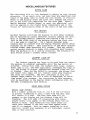
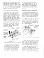
STOP BRACKET ADJUSTMENT
The following illustrations
show the Right Side of the Reel
Mechanism in the 3 positions
prior to Kick-off. These illusstrations show the factory standard average settings of the Stop
Bracket (Trip Arm) & Drive Shaft
(Trip Arm). Also shown are the
centerline dimensions and operating distances of various levers
& Shafts (as per engineering design).
It should be noted that
because of variations in tolerances, these given dimensions are
a general guide and may need calibrating when working on an individual machine.
REST POSITION ADJUSTMENT
The illustration (Figure 1) of
the Reel Mechanism is shown in a
rest position with all adjustments
completed for a proper operating
mechanism.
The dimensions shown
are reference points for checking
an adjusted unit.
28
The next setting to be made is
the Stop Bracket (Trip Arm).
This
is done by moving the bracket to
a pOSition when measured, that
should read approximately 1-15/16"
from the end of the Side Plate to
the inside form of bracket (see
Figure 11.
If the Stop Bracket is set back
too far the Trip Arm will fire
off before the toggles are locked
up (Latch Pawl) causing and uncoordinated reel spin.
If the
Stop Bracket is set forward too
far the Trip operating Lever pawl
cannot trip off the Stop Bracket
because the Handle is in a full
"down" position (full stroke
1 imi t).
At this time the Handle
will stick in a down position
until a Service Man opens the
Machine and manually releases
the Trip Pawl.
The setting of the stop Bracket
(Trip Arm) is extremely critical
STOP BRACKET (Unll :
ELAsnc STOP NUT (Inner)
TRIP OPERATING LEVER
r-GEAR ASSEMBLY
OPERATING
LEVER PAWL
TOGGLE LINK
TOGGLE STOP
Figure 1.
Reel Mechanism in Rest Position
for a proper kick-off and spin.
As you see in the Reel Mechanism's
Trip position (Figure 3), the
Toggle Levers are in a "full up"
position against the Toggle Stop
Rod and the Latch pawl has moved
under the Toggle Levers to just
touch the Toggle Stop Rod Locking the Toggles in an ·up· position (in turn cocking back the
Index Levers which release the
Reels). Also notice that the Trip
Operating Lever Pawl is against
the Stop Bracket and ready to
fire off. This is the correct
Stop Bracket adjustment position.
DRIVE SHAFT ADJUSTMENT
The Trip Arm Drive Shaft Adjustment is factory set according to
the dimensions shown in Figure 1.
This setting gives a full stroke
to the Trip operating Lever and
aligns the roller stud (actuating
Gear) with the Handle Mech. Actuating Arm. The alignment into the
Handle Mech. Actuating Arm is
essential so that the Handle Mechanism's full stroke actuation
corresponds to the Trip Operating
Levers full stroke actuation and
trip-off. When installing a Reel
Mech. back into the Cabinet see
that the Roller Stud aligns perfectly with the Handle Mech. Actuating
Arm.
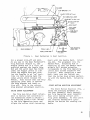
START MOTION POSITION ADJUSTMENT
The Start Motion Position (Fig. 4;
shows the starting movement of
the Gear Assembly, Shaft Assembly
and Trip Operating Lever Assembly
Pawl until making contact with
Trip Lever Assembly. At this point
the internal mechanism's cycle
begins its motion for cocking the
Reels.
29
DRIVE SHAFT
(Trip Arm)
n-
TRIP OPERATING
LEVER ASSEMBLY
4%
[~~~
GEAR ASSEMBLY
Figure 2.
OPERATING
LEVER PAWL
TRIP LEVER
ASSEMBLY
Reel Mechanism in Start Motion position
TRIP POSITION ADJUSTMENT
The Trip Position (Figure 3)
shows the cocked mechanism just
at the time of tripping the Trip
operating Lever Pawl which in
turn fires the Drive Lever (not
shown) to spin the Reels and unlatch the Latch Pawl Assembly.
Further rotation gives the proper
overtravel to allow completion of
all motion and positive latch. The
further rotation also brings the
Toggle Levers up to just touch the
Toggle Stop Rod. At this exact
moment, the Trip Operating Pawl is
pulled off by the Stop Bracket and
the trip off is accomplished, resulting in spin of the reels.
CYCLE TIMING SEQUENCE
The cycle timing is sequenced
follows: As the Handle is
pulled, the Trip Operating Pawl
contacts the Trip Lever and rotates it clockwise. Being pinned
to the Trip Shaft, it rotates all
~f the Crank Assemblies which
ere also pinned to the Trip Shaft.
These Crank Assemblies lift the
~oggle Lever upward and as they
~ass the notch on the Latch Pawls
che springs pull the Latch Pawls
'!f1der the Toggle Lever.
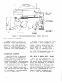
REEL MECH. TO HANDLE MECH. TIMING
JS
30
When all bench adjustments are
made to the Reel Mechanism we must
now insure proper relationship of
timing the Reel Mech to the Handle
Mechanism in the cabinet. The
Handle Mechanism is designed with
two features directly related to
the Reel Mechanism; the Full Stroke
Pawl which insures against reversal of handle movement until
trip of reels and the Secondary
TRIP LEVER
ASSEMBLY
1~
4Y.
l"'_'
TRIP OPERATING
LEVER ASSEM.
~~~~~~Ll"l.
TOGGLE
STOP ROO
TOGGLE LINK
Figure 3.
LATCH PAWL
ASSEMBLY
OPERATING
LEVER PAWL
P BRACKET
(
ip Arm)
Reel Mechanism in Trip position
Latch which locks the Handle in
the p'Jlled position until the
Reel Mechanism has tripped.
AIR CYLINDER OPERATION and SERVICE
The function of the Air Cylinder
is to insure a slight delay during
With the Reel Mechanism in place
a fast handle pull to allow the
and locked into position, the Handle Toggle Links to overtravel and becan be pulled by manually holding
come held in the "latched" position
the release arm at the top of the
by the Latch Pawl Assemblies. This
Handle Mechanism. By pulling the
slight delay gives time for the
Handle very slowly you can check
reaction of the related parts to
to make sure that the Full Stroke
fully function, i.e., springs to
Pawl on the Handle Mechanism does
pull latches under Toggle Link and
not reverse and release until the
Lever Assemblies.
Reel Mechanism has tripped.
Fast pull is also resulting in
if this does not occur, you must
holding back motion of the Drive
remove the Reel Mechanism from the
Shaft by the Air Cylinder. This
c,binec and set the center nut on
compresses the Spring Assembly in
the Drive Shaft slightly toward the the Drive ~rm during the slight
rear to insure simultaneous trip
delay and these springs then com~Ith release of pawl.
plete the motion and insure proper
function.
The second timing then corrects
itself to release the secondary
If it appears there is undue
latCh with the trip of the Reel
resistance to a Handle pull,
1"f'chanism.
check to see if the tiny hole
31
in the end of Cylinder (center)
is plugged (causing compression
resistance).
If it appears
there is no delay action to
cushion hard, fast handle pulls,
you may need a new Piston Cup
Seal. The Piston Cylinder should
he greased occasionally.
It is very important that this
Unit function correctly to insure
latch of toggles and proper spin
and index.
REEL UNIT OPERATION and SERVICE
The Reel Units should spin
smoothly and freely on the Shaft
with no resistance.
They should
also spin straight and true with
no warpage or wobble.
The Reel Hubs are equipped with
Needle Bearings for top performance and long life.
Lubricate
this Hub Unit (note hole) occasionally with a drop of our Lubriplate No.1 Oil, then wipe the
Unit off to prevent any oil spinoff on the Reel Tapes.
you will also notice a Screw
Operated Brake on the Hub.
At
the present time factory adjusted machines do not use the Brakes.
It is felt that a good spin gives
the best reel symbol mix.
However the Braking Screw has
certain applications where Reel
Speed control is desired.
In 1973 Bally introduced a new
stainless steel, anti-magnetic
reel as standard equipment. This
Reel is now available as a replacement part from Bally Parts
and Service. When re-installing
or replacing reel Tapes be sure
they are securely fastened.
The
Reel tapes are plastic laminated
and have a very tough smooth surface which is virtually stain
proof and indestructable. Because
of the very slick surface, the
Tape must be properly clamped
down in the Reel gripping edge
or slippage can occur. Any
slippage can throw off the relationship of the symbol to the
Index Wheel causing a confused
payout pattern.
---------- ELECTRICAL ADJUSTMENTS ---------REEL READER ASSEMBLY ADJUSTMENT
The electronic Reel Mech offers
an optical reading system which
requires proper positioning of
the Reel Reader Assemblies to
their respective Index Wheels.
To
accomplish this adjustment, simply
loosen the 2 mounting screws holding the Reader assembly to the
Reel Front Plate (see Figure 4).
Position the Index Wheel (as indicated in Figure 4) and retighten the
mounting screws. Repeat this
operation for each Reel Reader
Assembly used,3 times for a 3 Reel
game, 4 times for a 4 Reel, etc.
•'1\_~""i"'...--cc--'-\\ POSITION
REEL READER
ASSEMBLY SO THAT
INDEX WHEEL IS ' /16FROM THE LEFT P. C.
INOEX~~-';
WHEEL
BOARD ON READER
ASSEMBLY • • •
ROTATE REEL
ASSEMBLY TO
INSURE THERE IS
NO CONTACT AT
ANY POINT
REEL READER
ASSEMBLY
NOTE:
MAKE CERTAIN THESE
TwO WIRES ARE
DRESSED PROPERLY .•
LOOPED DOWN AN 0
AWAY FROM INDEX
WHEEL ~ A.S SHOWN
___;.->-_ LOOSEN 2 SCREWS
FOR ADJUSTMENT
FIGURE 4.
Reel Reader Assembly Adjustment
32
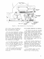
PROPER CAM SWITCH
SEOU!:NCE
I
i
ARM
KICK
SWITCH j SWITCH
REEL MECI1
SEAUPI.UG
1. REST POSITION
I
ARM SW1TCH
l-'-'''-'-----rI
I(IC~
2
SWITCH
GRQUNO
~
"
4
REEL READER
CONTROL
NORMALLVjNORMALI..Y
OF'EN
Cl.OSEO
------,,'NO CI<IANGE I
STA1IfT KANDLE PUl.l.
'OCI( SWITCH OPENS
<
i Otl£N J
i
OPENS
CONTINUE HANDLE
PULl. -ARM SWITCH
CLOSES
,CLOSES
NO
CkANGE
(OPEN)
SF'IN STARTS
SWITCHES SACK TO
REST POSiTION
OPENS
C:"OSES
KICK
SWITCH
IOARD
Figure 5.
Cam Switch Sequence
CAM SWITCH TIMING
Also, the electronic Reel Mech
incorporates a Cam Switch timing
which is quite simple to adjust.
All that is needed for this adjustment is the loosening of the
Reel Mech Cam (located on the
L.H. Side Plate) and moving it
to conform with the proper sequencing of the Cam Switches.
Proper sequencing of the Cam
Switches for electronic games is
described as follows:
Arm Switch - 53 Wire
Wired Normally Open Switch
Kick Switch - 54 Wire
Wired Normally Closed Switch
The states of these two switches
from rest position through one
game cycle, back to rest position
again, are described in Figure 5
showing the proper switch-cam
relationships.
---------- HOPPER PAYOUT UNIT SERVICE & ADJUSTMENTS ---------For a complete overhaul of the
Hopper Payout Unit, remove the
Unit from the game and remove
the scoop cover. Now follow the
general point by point procedure.
POSITION OF HOPPER KNIFE
Check the Hopper Knife (see
Fig. 6).
The forward edge must be
REAR LEG
A good cleaning of the unit is
in order. An aerosol type degreaser or contact cleaner can
be used, however, all parts must
be wiped off with a clean cloth
to remove any residue and desolved scum.
OPTO SWITCH
ROCKER 8 ROLLER
ASSEMBLY
ROLLER
After cleaning the Hopper Unit,
we can inspect and adjust the
Hopper in the following order:
HOPPER
WIPER ADJUSTMENT
Adjust wiper so that clearance
between pin wheel & wiper will
allow a single coin to pass.
HOPPER KNIFE
Figure 6.
WHEEL
Hopper Knife Position
33
against the Pin Wheel and touching
the edge of the Shelf Wheel.
No
coin should be able to wedge itself
between the blade and the coin disc
when being dispensed. Absolutely
no grease or oil should be applied
to the area or any other area that
comes in contact with coins.
the way of the opto-Switch as
a coin passes under the roller.
These conditions can be had by
either slightly increasing or
~ecreasing the form on the OptoSwitch mounting bracket to allow
proper pivot arm-to-light source
clearance.
HOPPER OPTO-SWITCH ADJUSTMENT
HOPPER MICRO SWITCH ADJUSTMENT
The next item to be checked &
adjusted is the Hopper OptoSwitch. This Opto-Switch does
the actual coin counting as coins
move out under the roller of the
Rocker & Roller Assembly.
The
pivot action of the Roller ASSy.
allows the rear leg of the roller
assembly to be removed from in
between the light emitting source
and photo transistor of the OptoSwitch. Each transition from
light blocking, to Opto-Switch
operation by removing pivot arm
from light path, back to light
blocking, records one coin-out
pulse (See Figure 7).
The old Hopper Opto-Switch has
been replaced by a conventional
Micro-Switch to allow for more precise adjustment.
The switch contacts are of the low current capability, gold-crosspoint nature.
PHOTO
TRANSISTOR
Adjustment on this new switch is
quite simple. Loosen the nut on
the rocker and roller ?ssembly,
screw the adjust~ent screw down to
within 1/32" of the switch actuator blade and then re-tighten the
nut.
(See Figure 8)
ROCI(ER B ROLLER
AOJUSTMENT SCREW
\
•• • AQJUST SO THAT
SCREW IS 1/ 32 " MAX.
FROM BLAOE OF • • •
UGHT EMITTING
SOURCE
AS COINS PASS
UNOER ROLLER . . .
a
~~~~~~:~~~~;:.
~ JiilL~~
ROCKER
ASSEMBLY ROLLER'"
PIVOTS
•• . ALLOWING
'§
REAR LEG TO aE
"CLEAR OF LIGHT
~
BuTTING SOURCE
fV'.u--:
Ii
•. • THUS
RECORDING
Figure 8
Hopper Micro-Switch (Later Models)
ONE "COIN -OUT-
PULSE
~
•
Figure 7
Hopper Opto-Switch (Earlier Models)
The main points in adjusting
the Opto-Switch are to insure
that the rear leg of the pivot
arm is completely blocking the
light source from the phototransistor of the Opto-Switch
when the arm is at rest, and
the leg is completely out of
34
Check the switch with an actual
coin under the roller arm to insure a positive switch actuation.
Also, make sure that the switch
is at a rest position when no
coin is present under the roller.
Detecting the coin earlier or
later as it passes under the
roller is controlled by the screw
adjustment on the rocker and
roller arm assembly. Bending the
switch actuator is not necessary.
HOPPER COIN CONVERSION
ROCKER PIN SET SCREW ADJUSTMENT
CRAW SET SCREW SNUG SO THAT ALL
Coins of diameter .~69 to 1.115
use parts; Pin Wheel P-842 (16 Pins),
Shelf Wheel P-847 (specify coin).
In
the conversion to the Dollar, the
Coin Spider Assy. A-3750 is deleted,
and replaced with a Drive Bushing
S-231-826 and Screw LSPR-1032-1116.
Pin Wheel P-842-1 (12 pins) is used
for all coin diameter 1.120 to 1.500
Shelf Wheel P-847-6 is used for the
Dollar coin along with a new Agitator,
R-526. A Hopper liner P-834 is also
added to the Hopper for the large
Dollar coins.
IIL/l,Y '.S 1IU(EN·Vl":-T'HEN SACK OFF
SCReW Sli(;H'I"L1' ••• ANO ROTATe:
P1NW"!£EL
ey
HAIliC.
P NWHEe:..
SHOlii..O TI.)I'<N WITHouT BI!'.. OING
to TiQh! ) OR WOSsuNG {Sere.
(Scr~w
/
(
'0 '.. cose )
CAUTtON- OVER-TIGHTE.IH~G
WILl.,. OVERLOAO BEARiNG AIliO
/"" ';7'
Figure 9.
P!NW;';EEl WILL Nor TURN FREELY
Rocker Pin Adjustment
HOPPER COUNTER BALANCE ADJUSTMENT
hdjustment is made by
first filling the Hopper
with the desired level of
coins. Then start the adjustment with the Micro-Switch
in tre up position (see
Fig. 10). Adjust Set Screw
screwed into a clockwise
posit:on. Now back off Set
Screw ~ounter-clockwise
very gradually until Micro
Switch clicks into the down
position.
Now Hopper is
set at the given desired
capacity.
HOPPER
~
~\i
\
"'\
(!)
FILL HOPPER
WITH THE DESIRED
LEVEL OF COINS
o
TIGHTEN SET SCREW
(Turn ClockWise I
••• UNTIL ACTVATOA
ON MICRO SWITCH
IS IN THE UP POSITION
(Just touching head
of Adj. Screw)
CD
.
~
Figure 10.
NOW BAC" 01'1'
SET SCREW {COllnter'
clockwise 1 UNTil
MICRO SWITCH CLICKS
SET SCREw
MICRO SWITCH
INTO THE DOWN
POSmON
TENSION SPRING
Hopper Counter Balance Adjustment
---------- HANDLE MECHANISM SERVICE ---------It is the Handle Mechanism which
initially receives the impact of
~ ~ard Handle pull.
Because of
tnt tough requirements, this unit
must be of the strongest construction.
As a safety factor the
Handle, Mechanism is built to
specifications ten times the
necessary strength to protect the
Reel Mechanism from the most
agressive player.
There have been several new
developments designed to strengthen and protect the Handle Mech.
First an anti-fast pull Speed
Lock (note ratchet) was added in
1970.
In mid-1973 the Full Stroke
Pawl & Locking Links were redesigned and strengthened.
You will notice that these improvements can be incorporated on
35
Older Machines.
It is also
suggested that the new front,
Anti-wiring Shield be in place
at all times.
duty pivot points and our Hydrotex Lube #hSI on points of heavy
stress and sliding parts.
Because of the heavy duty use,
the Handle Mech. should be lubricated periodically.
Use our
Lubriplate No.1 Oil on the light
Be sure
Speed Lock
its pivot,
Ratchet on
principle
the anti-fast pull,
Pawl swings freely on
since it engages the
a centrifugal force
(do not lubricate).
MOLEX PLUG SERVICE
NOTE: The Molex Pin Extractor Tool enables easy
service of the Molex Plug, Pins both male and female are removable. Holding Extractor Tool as
shown in Illustration, placing Forefinger over shalt
as to hold it from turning (as shown), push Shaft over
Pin giving Tool a slight twist allowing the Pin Fins
to compress easily, thus enabling the Pin to be pushed through
~;:rlon
Housing.
BALLY NO.
FEMALE
E-663-2
FEMALE
E-663-4
MALE
E-661-2
MALE
E-661-4
MOLEX NO.
02-09-1104
02-09-1119
02-09-2103
02-09-2118
TYPE
1190
1381
1189
1380
II
001
=-
TYPE 1189-90 LONG EAR
TYPE 1380-81 SHORT EAR
HAND CRIMPING TOOL HT-I031
NOTE:
rT~__
OC::c::;.
REPLACEMENT ITEMS CAN BE ORDERED (
THRU BALLY DIST. OR NEAREST MOLE}(
REP. IN COUNTRY OF USE.
~
II
EX'RACTCR
"_O_l_"_HT
1031
L~ ~n
'---"~
SHORT EAR
[ =:J~
MOLEX PLUG RECEPTACLES
-------,
L CE=====' (~i(Wi!!wi(i(i@~
REPLACEMENT PART HT 1010-232
/=-=:::J>" (ITJ
MALE
2 PIN PLUG
660-2
4 PIN PLUG
660-4
12 PIN PLUG
660-12
STATE LAWS FOR POSSESSION OF SERIES E 1980-1986
FEMALE
662-2
662-4
662-12
January 1.1995
Any Machine Legal: Alaska. Arizona, Arkansas, Kentucky. Maine, Minnesota. New Mexico.
Nevada. Ohio, Texas, Utah, Virginia, West Virginia. Pre-1984 Models: Colorado
Machine Must be 20 Years or Older: Florida; 25 Years or Older: California. Delaware.
Illinois. Iowa. Louisiana. Maryland. Michigan. Mississippi, Montana. New Hampshire, North Carolina,
North Dakota, Rhode Island, Oklahoma, Washington, Wyoming and \Visconsin.
30 Years or Older: Massachusetts. Missouri and New Jersey
(ownership is still illegal in the unlisted states, but check with a dealer. trade magazine or your state officials frequently
as the laws are becoming more favorable)
HOT TIP
To purchase Bally SERIES E slots contact your local dealer, attend the antique coin shows and check the ads
in the trade magazines and the classified section in newspapers. To verify the model of a machine with the
year of manufacture refer to Bal1.v Slot Machines: An ltlustrated Guide to the ll4 Most Popular Bal(rs Alade
from /964 -/987. For ordering a copy of this book. see page 64 of this manual.
36
LUBRICATION GUIDE
POINT WHERE
LOCK
LEVER ENGAGES
POiNT WHERE. LOCK LEVER
ENGAGES RACK LOCK LEvER
UGHT COAT OVER ENTIRE.
LOCK
HANDLE RELEASE
PAWL
ASSEMBLY
ASSEM elY
ENOS OF SHAFT OF
80TH ENOS OF SHAFT OF
STROKE PAWL ASS£M.
THAT COME THRU BUSHINGS
IN 80TH StDE PLATES
LOCK PAWL ASSEMBLY
THAT COME THRu BUSHINGS
iN BOTH SiDE PLATES
IN
GUIDE SPRING
SHAFT
SHAFT>
BOTH SIDES
OF SUPPORT LI N K
SHAFT.
BOTH SIDES
OF ACTUATING LEVER
HANDLE IS HELD IN
PLAY POSITION
i COM PLETEL '( DOWN)
SO THAT
PIVOT STUD.
60TH SIDES Of
ACTUATING LEVER
AND LOCK PAWL
. LUBRICANT CAN BE
APPLIED TO TEETH OF
RACK LOCK LEVER
ALSO
BOTH
SIDES OF
RACK LOCK LEVER
CAUTION:
00 NOT ALLOW ANY
LUBRICANT ON
LATCH PAWL PIVOT
I, I,
OIL.
BEARING AND
OIL.
LIGHT COAT
BOTH SIDES OF PIN
I
I
NOTCHES
B01H SIDE S OF
LOCK LINK
PIVOT STUD.
80TH SIDES OF
LOCK LINK
Figure 13.
o
c
Han<"lle Mechanism
BOTH ENOS OF PIN
Of ROCKER AND
ROLLER ASSEMBLY
OIL.
SHOULDEfl: PIN
OF ROCKER 8
ROLLER ASSEMBLY
SURFACES AND ROLLERS
OF MOVING LINKAGES
IN AREA SHOWN
Figure 14.
Hopper & Rocker
~ssembly
Figure 15.
Front Door Hinge
37
LUBRICATION GUIDE
INDICATES •.. USE HEAVV
~_I"" INDEX
o-un
AND INDEX LEV£R
ARMS ROTATE
LEVER PIN
INDICATES.,. USE
LU8RiPLATE.' OIL
LEVER •.
WHERE INDEX LEVER
INOEX
HYROTEx LUBE -651
DRIVE
(MARVEL MYSTERY OIL)
LEVER PIN
eASE
INDEX LEVER SHAFT
••• WHERE INDEX
LE.vER AND DRiVE
SP~ING
LEvER ROTATE
STUD OF
cnANK ASSEMBLY
LATCH PAWL
••• 8ETWEEN
TOGGLE LINKS
AND ON NOTCH
TRIP SHAFT •••
WHERE TOGGLE
LEVER 8 CRANK
ASSE'-I, ROTATE.
PINS THAT CONNECT
TOGGLE LINK TO
INDEX LEVER ANO
TOGGLE LEvER
TRIP SHAFT .. '
~
WHERE IT ROTATES
IN eUSHINGS ON
BOTH LEFT
RIGHT
SIDE PLATES
SHAFT WHERE LATCH
PAWL RCiATES
a
LINK
,i
EDGE OF
MICRO SWITCH
CAM - LIGHTLY
PIN HOLE AT BAl.I'\.
~:
OF AIR CYLINOEP
SHAFT THRU TRIP
.J..>-""""'.LJOPERATlNG LEVER
LEVER ASSEMBLY
(T~;;:n~,-r.'\ UNIVERSAL
COUPLING
WHERE IT ROTATES
IN TRJP OPERATING
LEVER
ON END OF DRIVE
SHAFT NEAR EST
OVERTRAVEL FORK
TRiP ?AWL STUD
TRIP PAWL
a
lNSIDE SURFACES
AND HOLES OF
QVERTRAVEL FORK
LOWER EDGE OF
ALSO HOLES o~
CAM GEAR ASSEMBLY
TRIP LEVER
P!N •.• BETWEEN
CONNECTING ROO
a GEAR ASSEM$L'I'
ROLLER ON TR!P
LE"ER ASSEM al '(
ROLLER ON
GEAR ASSEMBLY
iNSlDE SURFACE •. iRIF'
LEvER STOP BRACKET
TEETH OF 80TH
PIN ••• LEFT & RIGHT
LOCK LEVER
Figure 1 L ~
38
A3SE~~L
GEAR
ASSEM BLI ES
SHAFTS a NYLINERS
OF eOTH GEAR ASSEM BUES
Reel ]\1echanisr;1
(Soft Cushion)
LUBRICATION GUIDE
T
L!J
IN DEX
INDICATES • . USE HEAVY DUTY
HYROTEX LUBE "'6~1
INDICATES •. USE
LUBRIPLATE - I OfL
LEVER
INDEX
I
LEVER ARM
INDEX LEVER
ARM SHAFT
>
DRIVE
LEVER PIN
(MARVEL MYSTERY OIL)
BASE
INDEX LEVER SHAFT
. , WHERE
INDEX
LEVER AND DRIVE
\ SPRING STUD OF
ASSEMBLY
LEVER ROTATE
SLOTS IN
DRIVING LINK
PINS THAT CONNECT
TOGGLE LINK TO
TRIP SHAFT. .•
WHERE IT ROTATES
IN BUSHINGS ON
INOEX LEVER AND
~
TOGGLE lEVER
SHAFT WHERE
PAWl.. ROTATES
....2~~~;;;-;~"---\!:J LATCH
a
BOTH LEFT
RIGHT
SIDE PI..ATES
PIN THAT CONNECTS
UNf(
PIN ASSEMBLY
a
TO TRIP OPERATING
LEVER
OPERATING LEVER
SHAFT THRU TRIP
I.EVER
LEVER ASSEMBLV
UNiVERSAl.. COUPLING
WHERE IT ROTATES
IN TRIP OPERATING
LEVER
INSIDE SURFACES
AND HOLES OF
r.-u~
QVERTRAVEL FORK
o
"
• • • ALSO HOLES OF
CAM GEAR ASSEMBLY
;;;
SURFACE •• TRIP
stoP SRACKET
PIN ••• LEFT
a
TEETH OF 90TH
GEAR ASSEMBliES
RIGHT
LOCK LEVER
a
SHAFTS
NYLINERS
OF BOTH GEAR ASSEMBLIES
Figure 11.
TEETH 8 EAR OF
LEVER LATCH
Reel lI1echanisr.1
39
CABINET ASSEMBLY· Part One
CHIME
(SERIES 1000 ONLY)
DESCRlmoN
1 CA-1164-1190
2 A-2919-32
3 CA-116S-210
P-I973-534
5 £-108-170
Clblnot
Clblnot Liner
cabinet _
•
~
~
,
IT!!! PART 110.
6 C-l068
,
CPA0-632-1P03
Swi teh I'ountlng l!rkt.
Switeh
Switeh Cap
Set Strew
Bracket Mt«. Hinge
P-641 ... 1
Bracket !linge Protector
Hinge Qj8I'<I
9 M4SS
10 CMR-25020-1124 Carriage Bolt
P-6641.10
SPIW' 51....
11 P-626"',89
Board !'tg. Ilracl<et (2)
12 P-6665-663
I'ount!ng Bracket
13 M-191S
Pr!nt!d Clrcu!t Gu!d!
I/O Board All_Iy
AS-298Q.S600
15 AS-2978-1
foIPU Board Allsembly
I'ountlng Bracket
P-6665-692
22
7 P-6295-1
,.
; I
I
I
I
Ii
I I
I
I
~
II
16 P-6416-1
17 P-6280
"-1348-1
17A CMR-2502!l-1118
175 M-1757-2
lP c-641.31
"-202!l-1
P-1158-6
19 AS-2303
20 P-6281
21 AS-2301.11
40
22
Bar LoeIc
23
Dioe I'ountlng
Clrriago Bolt 1.1/4 (3) 2'
Carriage Bolt 1-118 (1)
2S
Nut • Spec!al (1)
Hub
Plug !btlon
Spring Washer
Randle_ly
Plat. Mounting
Handle I'eeh. As.embly
26
27
28
29
E-66U-29
P-62!18
"-1372_10
"-1702-23
P-1973-319
RLPP-632.1804
P-511
LSPR-l032_1104
P-6406-74
RLI'P-l032_1806
P-6665-345
5-231-794
Molex Handle Lockout Assem.
Actuat!ng A!"I!1
Bolt
5/16 Int-Ext Loekwashor
Handle I'eeh. Cover
Screw
Guid! Rall _
Plate
So....,
Rail su!de - Left
So....,
Gu!d! Ra!l Mount Brkt.
a.ah!ng
30 P-6406-75
31
32
33
34
'l'Fl'P-l032_1806
P-6268-'1
P-6268-3
P-66i\5-337
SAPR-aOO-ll10
£-66....19
M-1366
£-587-19
£-6620401
£-663-1
Sm-aOO-1114
Ra!l Guido - R!ght
So,...,
Ra11 Mount Brkt. - Ro.r
Ra11 Mount Brkt. - Front
Bafne (2)
So,...,
Bell & Receptacle As.em.
Bell
Diode
4 Pt. Molox Reoepteolo
Terminal
Sor...
CABINET ASSEMBLY
Part Two
Note: On the Series 2000.
the Fluorescent bulb in
the Top Sign replaced the
incandescent bulbs used
on the previous models.
1
2
3
4
5
6
7
8
9
10
11
12
13
14
15
16
17
18
19
20
21
22
E-126-43
P-150-70
P-150-70
P-1S56
P-8157
E-664-20
A-4000-2
P-1560-2
E-644-15
M-281-44
P~3413-7
E-l08-181
P-758-17
P-7588-50
E-644-12
P-6264-188
P-6665-644
M-1915-1
AS-2982-1
E-l03-67
E-122-151
P-6442-232
23 E-148-13
110 V line Cord
Fishpaper Shield
Plate
Screen Cover
Fan Screen
Molex Fan Assem.
Fan Baffle Assem.
Plug Mgt. Bracket
MoJex Buzzer
Assembly
Lock
Lock Bracket
Door Switch
Lock Cam
Outlet Bracket
Outlet Plug Assem.
Power Supply Bd.
Mounting Brld.
Mounting Brk!.
P.C. Board Guide
Power Supply
Board Assembly
Transformer
Fuse Mounting
Bracket
Fuse Block
5 A. 3AG Fuse
8A. SAG Fuse
10 A. 3AG Fuse
26
24 E-664-38
25 E-146-806
26 P-6417-3
27 E-574-12
28 P-7990
29 E-664-22
30 E-664-16
31 A-SOI8-1S
Molex Delay Relay Assem.
CR Relay (6VDC)
Socket Mounting Plate
18 Pt. Socket
Power Switch Cover
Power Switch Assembly
Molex line Filter Assembly
Coin Chue Assembly
32
33
34
35
36
37
A-1450-9
P-8665-160
A-3400-XXXX
P-182o-2
P-372-7
P-8261-5
Insert Latch Assembly
Insert Stop Bracket
Insert & Lamp Socket Assem.
Bracket
Bracket Insert Latch
Light Reflector
3S
E~12(J..120
Starter Socket
39 E-411-8
Ffourescent Starter
Flourescent Socket
eanast
Grommet
13W Fluorescent lamp 12 In.
Feature Glass
P-6242-28 Glass Retainer - Upper
P-1925-211 Corner Bracket
47 P~6242~112 Glass Retainer - Side
48 P~6242w120 Glass Retainer - Lower
40
41
42
43
44
45
46
E-120-139
E-409-10
R-111-8
E-412-18
41
FRONT DOOR ASSEMBLY
(Front View)
2
3
35
12
13
31
30
I
I
I
DESCl!IPTION
I'm' PA.RT NO.
, C-859
2 R-3~O
1 R...2' .... 3
4
A-2S75-'
5 £-108-97
6
Upper Iloor- FT_
Sponge Rubber - ~el
Rubber StrIp
Hinge Assembly
Push Mton Switch
AS-2342
Rejector Uses:
Coin Slide Assem. (5,10.25)
AS-2342_1
Coil'! Slide bsembly {SO)
A5-2342-3
Coin Slide A!:!!If!m. (5. '0, 25)
Coin Slide Assembly (50)
Coin RIq) Shield
~&n1e81
Elect. Coin Comparator Uses:
A5-2342~
7 P...7119-'1
8 C.-<71
Clip
N-832-<112 llut
9 P-6426
Scavenger Htg. Breoket
10 ~P-399-9
Torsion Spring
!1 A-<929
Seavenger Assembly
12 C-854
Lower Door FrI!l'M! (5,10.25)
Lcwr Door fr .... (50)
0-854-6
13 .-6665-75 Botta!! Door Shield
42
14 ~..¢06-29
15 C..¢60-10
C..¢60-11
16 P..¢441
17 P-7209
18 C-655
LSl'R-812-110B
19 A-3621-<6
R...21-32
~Pl\-812-1108
20 E-li09_10
21 R-111-8
22 £..¢6C>-200
E-661_1
23 E-662-<DO
1:-663-1
24 .-"09-14
LSPR-632_1104
2'i £-120-120
LSPR-612-110
26 .-li11-8
E-66Q.JlOl
E-661-1
2B E....09-1
Trill Panel
29 £-411-7
Coin CUp Guard Plate
30 E-I20-139
31 E.... '2_18
Col. CUp
32 G-35o-=
50,....
Glass Retainer Assembly 33 A-316o-17
34 0..349-=
Rubber Strip
35 C-658-3
50rell
36 A-30BS
Ballast
37 C..¢74
er"""",t
C-674-1
2 Pt. ~lex Plug (4;
C-67....
Terminal
C-614-3
2 Pt. Receptaole (3;
38 5P-<OO-38
Terminal
...... 48-1
Pallast (4 Watt)
39 M-I376
50rell
40 5-287-1'
Starter _
Weld Screw
~xtruded
Trim (5.10.2<;)
Extruded Trim (50)
-
F'lourelSeent starter
27
.,
.It Pt.. Holex Plug (2)
Terminal
Balla:!lt
Fluorescent Starter (2)
Laftpholder
Fluorescent
Lamp
Display Gles
Retainer Frame Aasem.
Reel Window Glass
Window Frlll'!le
Scavenger
Coin Drop
Coin Drop
Coin Drop
Coin Cr-op
Illtton Assem.
Casting (1~)
Casting ( 54)
Cuting (25<1)
Casting (SOt!)
Compression SprIng
~nap
Wa3her
Push E\1tton Disc
Button HousIng
'-33~9'"
Retaining Ring
5-286-<8
Push Button
P-6316-6
Retaining Ring
FRONT DOOR ASSEMBLY (Rear View)
1 C-1154-1
Lower Door Frame
2 C·1159·1
Upper Door Frame
Lock Side Protective Brld.
Guide lock Slide
Lock Slide Assembly
Door Frame ~ Right
Lock
SwHch
2
Lock Cam Assem.
Cam
Lock Crank
Light Brk!. Assem.
Lampholder
18---!~'iI'.J-i
3
4
5
6
7
8
9
10
11
12
13
P~7120
P-6428-4
A·2921H
C..sS7-2
M-281-40
E·l0IH83
A-2930-5
P-816·14
P-8427
A·2938-81
E·120-119
26
21
\
34
58
~~'~i
.
I
_"
•
~ ,41
_.
46
14
15
16
17
18
19
20
21
22
23
24
25
26
27
28
29
30
31
32
33
34
35
35A
E-412·11
P-8442-271
A5-2985-2
E·120-134
R·111-8
E·125-2
E·120-120
E-411-7
E-408-1
E-662-401
E-66Q.401
E-660-200
p·n86-7
p·n66-6
E·120-119
E-660·200
E-412-5
A·2937·31
A·2937·34
A·2937·25
E·125·S
E·125-2
C-657·3
A·2938-65
A·2938-64
/
i 51A
'" 53 l ~
..,
43.
"'"
tar..
"
45
\ \
..
Flourescent Lamp
48>.
Counter Bracket
/
Display Board Assembly
.• •
-"ID
Lamp Socket
Grommet
#47 Lamp
Slarter Socket
Flourescent Starter
49
Ballast
35B e--664-71
Fluorescent Socket Assem.
4 Pt. Molex Receptacle
E·I20·119 Lampholder
4 PL Molex Plug
35C E-412·11
Fluorescent Lamp
2 PL Molex Plug
Reel Mask (22125 Stop)
36 R·111-8
Grommet
37 E·120·178 Lamp Socket
Reel mask (20 Stop)
38 E·I25·2
#47 Lamp
Lampholder
39 P-8665-744 Reflector
2 PI. Molo. Plug
40 P-8118
Plug Mounting Sracket
Flourescent Lamp
Light Baffle Assembly (22125 stop) 41 G-348
Windows
42 C-l073
Coin Extt Ramp
Light Bailie Mounting Bracket
43 P·I5().l00 Insulator
#83 Lamp (2)
44 AS2517·9 Coin Deflector Assembly
#47 Lamp
45 A·2929
Mount Mtg. Plate Assem.
Door Frame· Left
Shield Assembly (5-Line)
46 E·120·132 Lamp Socket
Shleid Assembly (3·Line
47 E·I25-6
#63 Lamp
Fluorescent Light Shield As.em.
48 A·301I1--n Coin Slide Assembly
~
.
49 A-3316-1
Coin Diverter Ramp
50
51
52
53
54
55
56
57
58
59
60
61
62
63
64
65
66
67
68
Coin Guide Side
Cover Plate
Coin Deflector
Coin Chute
Coin Baffle
Light Mtg. Plate Assembly
Ballast Starter Assembly
Ball.st
4 PI. Molex Plug
Starter Socket
Fluorescent Slarter
Rejector Mtg. Assembly
Extension Spring
SwHch Mig. Bracket
Spring
Coin Guide Spacer
Coin Guide
Coin Guide
Coin SWITch & WireAssom.
P-6702·1
P-6429·14
P-6798·3
P·569·126
P·569-125
A·2925·8
AS-2335·13
5E-409·1
E-66Q.401
E·120-120
E-411-4
A·13SII--50
SP·148
P-6692-1
SP·199·16
P-6431·XX
P-6695
P-6664
AS·2744·19
69 A&-2517·14 Coli Magnet Assembly
70 A·295IHX Armature Assembly
43
3 REEL MECHANISM ASSEMBLY -
Wide
1 Side Plate Assembly - Right
2 Tier Bar Bracket
3 Selector Base
4 Plug Mounting Bracket
~---
5 Nyliner
6 Trip Shaft Assembly
(Includes Items 8, 9 & 10
7 Bushing
8 Toggle Lever & Bushing Assembly
9 Crank Assembly
10 Bushing (2)
11 Toggle Lever & Link Assembly
12 Spring (3)
13 Index Lever Shaft
t
'-
"',oS
~.
12-
14 Index lever Assembly
,0
15 Index Lever Arm Assembly
(!
o
a
"
1I
<0,
"
"
~
'",
'",,~-
¥pl.-/--'
''ft
1·,-.g
~
~"
II
/
/
~
16 Roller
17 Index Lever Arm Assembly
18 Nut & Spring Support
19 Torsion Spring
"
~
49 Plunger
39 Position Bracket Assembly
(Includes Items 37 & 38)
20 T09gle Link (20 or 22, 25)
21 Pin
22 Index Lever Arm Assembly
(20 or 22, 25 stop)
23 Spring
24 Drive lever & Roller Assembly
25 Bushing (part of item 24)
26 NyU.er
27 T09gle Stop Rod
28 Latch Pawl Assembly
/
/
30 Spring - Green (3)
31 Spring Rod
32 Side Plate Assembly - Left
33 Switch Bracket
34 Arm Switch
40 Front Plate
52 Core Plug assembly
41 Front Plate Stiffener
53 Reel shaft
54 Reel
55 Spacer (Wide)
56 Reel Tapes (20, 22, or 25 stop)
57 Reel Clamp (Wide)
58 Hub & Bearing Assembly
59 Index Disc (20, 22, or 25 stop)
60 Retaining Ring
42 Plastic Spacer
43 Reel Reader Control Board
44 Channel - Reel Support
29 Pin
35 Kick Switch & Bracket Assembly
36 Cam & Hub Assembly
37 Reader Bracket Assembly Righi
38 "'umlnatlon Bracket Assembly
50 Compression Spring
51 'J' Coli Assembly
45 Reel Shaft Support
46 Index Coli & Base Assembly
47 Plunger Guide Bracket
48 Snap-In-Llner
:+
REEL MECHANISM ASSEMBLY
~26
Right Side
"~~~,,
~'; .:~
, _~J¥~
:
~'
2
I
(] f::l '
I
~
I
.~.l
U!'',-
~/'/
/'
<...
1
2
3
4
5
6
7
8
9
10
11
12
13
14
15
16
2874-21
C-537-31
A·2903
A-2903-2
P-126-541
SP-l00-21
P-6451
P-6287
P-6282-8
A-286S-1
A-171-1
5-739-157
5-2033-1
P-800-2
P-1637-11
P-801-21
Side Plate Assembly (Right)
Nyliner
17 SP·200·226
Gear Plate Assembly
Gear Plate Assembly (Back)
SP-200-225
5-156·591
S-231-911
M-319·10
A-199-2
SP-l00-12
A-178-1
5p-l00·241
M-331-1
A-286S
R-116
P-474
M-1481-27
Sp-l00-312
Plate
Extension Spring
Stop Bracket
Bracket Stop
Lock Lever (Right)
Gear Assembly
Over Travel Fork
Coupling Pin
Drive Shaft
Washer
Rail Pin
Washer (2)
,.
Overload Spring
(Outer)
18
19
20
21
22
23
24
2S
26
27
28
29
30
31
!
Overload Spring (Inner)
Shoulder Bushing
Bushing
Elastic Stop Nut
Trip Operation lever Assem.
Extension Spring
Trip Lever Assembly
Extension Spring
Felt Plug
Gear Assembly
Bumper
Bumper Housing
Split Spacer
Extension Spring
!~
,
c
32
33
34
35
36
37
38
35 38
3~36
,
Link
P-645-1
5-739-16-0 Coupling Pin
Piston
5-369
Piston Cup Seal
R-1211
5-1071-83 Rod (Air Cylinder)
Bushing (Air Cylinder)
5-231-41
Cylinder
C-112
HANDLE LOCKOUT ASSEMBLY
1
2
3
4
5
6
7
8
9
10
11
12
13
14
A-636-22
P-4S4-S9
A-3990
5P-399-43
A-3989
P-6316·4
5P·100·334
5-496-230
C-342
P-l08-53
C·31-2600
A-613-33
E-405-14
E·l0S-300
E-662-200
Lock~ut Mounting Plate Assembly
Spring Hook Bracket
Release Pawl Assem.
Torsion Spring
Plunger Stop Link Assembly
Retaining Ring
Extension Spring
Plunger
Guide Ring·Nylon
Coil Bracket
Coil
Core Plug & Bracket Assembly
Terminal
2.7K, 2W. Resistor
2 Pt. Molex Receptacle
45
REEL MECHANISM RELATED BOARDS
*I
<-.J:!rl.I<lli..
,j}'
J\-
..illL
!,-f iiflllut..~tQIJ{""
to'" Jij1I1U~~SO\. ..M,,,..
I
II; 1tfl.I(~" ~~
~
f'iilwZ'i m,
''"
U
••. U .....@"UI."SOl
J!'
~I
.(~!Q..!,-tTI
f.I"'",""-- - -f.:-
~'
l" H-gij; ; :!~ ; - -..::~
.... = -;~ J .s'- -"""'-'i
- -~.v.;t !).,~"
' ",
•• ,";:--"'-,
• -• ,,~
jjIh._·"''''''+I'~:•"""
,~, T'.ol.!"~
Gfl'
r ,'' ' '
;
" ,:1ll.""
~,~' -'+>+"
<r.n~:l
'....
,.
o
o
..
o
,4'10";- JJI1fl»ifllOl
L::: t·:" Ii.
!:
L", I: :
I
Ii
, t>!l~:
"i:"
,,!
": "
•Lr:""
"
" ",
. .-;; "'''
•"
".
: ••
'\..n 1111
I'
-"'.,
',-+
Jii)l.J
,• 1:- JIll
,
.Jlli.
~
,
~
''''"'Iei
• r I! _
'I' .J
: !,!<;",I I, 'I "
II
"",:
IT 0
:
"
"
<-
"', ...c-lilJ!"""."
'~'''....':.
".L--:.
'I . .._ -I
~-'<I!I'-.
:«l '
,
,,~>'
~ '1'U-P"U1
''':, {jD""".". ' "
J)'!I*
. . . . . ., ' ,
,'"''
"." [jjJ..." .... ,
JJ 1).('-
;." -""'rt
".f
,~~1'
J2
:t
...."
•
..
,~
:'
lie
"
I
!•• J
T
~:.J~
POSITION
POSITION READER
IIIUOEIil
(early
"
"
5 Volt
m(Jdd~)
,
,'0
illcalH.!t\CCl1l
tnmps & photo
'}
-l~~_"!,-.:"','"H..•••
."
(}
lrall\l!.t(H
, "',LLLLLllLLLLLfII
., ,,"'"
1n,
'5°
"=5t';;-
'-: "
':_ . . _."'''
'0
The Reel Reader Control Board is located on front frame of Mech.
'Cabinet Cable 1/0 Board Connector J I-Pins 19 & 20 are used
for 3, 4 Reel Mech. 12-Pins 14 & 16 are used for 5 Reel Mech.
AS-lill·1 10tiliOI RUOE! mfIBU
SlilOl
IIRl 10,
1'3133·2
j-3931·3
11 • 15 Hl$-6!
01 - 01 !-5I5-55
II
£-184-111
/I
!-168·16
D!StlIPHnN
lllllltCI!! 1SS!lBl!
iIIO!! Iltcm Until!
5 lOll UII
ill PHIIDlitlSmO!
4!D 11111 'lTla!Slllla
II til, 11110 lllilll!l! Itm
POSiTION ftfAOElIIi ASSe: ... I..Y H•• l
0
P 2948-359 AS 2983-1
Ac~IIIII'U 1111111:-
.,--=
J2
S2- •
=
=
=
=
=
-
""j;,
R'-=--
R3-c::l-
$3'---'
0
CR'
--=-'"
-c::::J-R4
-c::::;.RS
0
8
8
-Stc::J...A9
-<:::)..R7
+-rn:::::J>-ct
-=-R,
-=-R.
-c::::3- Rl0
-c::::Joo. fill
-c.:J-R12
-<:::>-C,
-c::J-fl13
.....c::rR14
aMf/(
J3
0
r"'i:f,I~
POSITION
REAOtlil
k
"
(,:[1:
lq
",
••
_
;..
[ifJVAUI)OArA STItOH
JI u (
II
1-1"1 II
ni"H.lft'"K)
READERS
140R'S
lu
'oj,
"'-""',.
Ek
-:
1,.--,.
Ci"""'- - -.::::"_,
:'
JI
nn~
Jl.t4(
Jl'U
UU RUDU CONTROl.. IOARO
-n--'
II-l~~
oO~
o
.. ----to} !gsmoH
--------::::::::::::::: -----1-___
~R1S
11111111111111 AII'
0
AS-2983-1 REEL READER CONTROL BOARD ASSEIBll
SYIBOl
UI
U2
U3
CRI
RI - R2
R3
R4 - R5
R5 THRU RID
Rli THRU RI5
CI
C2
Jl, 13
12
81
82
S3, S4
PART RD.
E-820-55
E-626-15
E-820-63
--
£-105-230
£-105-260
£-105-236
E-I05-283
E-I05-230
E-588-B
£-585-85
E-188-18
ROT USED
---
OESeR IPlIOR
1411 HEX BUFFER/D.C •
14CI4 HEX SCHMITT IRD
14145 BCD/DEC. DECODER
WIRE IUIPER
I KOKI RESISTOR 1/4 1m 51
410 OHM RESISTOR 114 JUT 51
I I OHM RESISTOR 1/4 IATT 51
41 I OHi RESISTOR 1/4 'ATT 51
I KOHl RESISTOR 1/4 IITT 51
2 lifO 50 Y. ELECTROLYTIC
.01 IFO 50 Y. CERIMIC
16 CIT. KIIOD RIGHT INGLE IAfER
i
i
l!-l91H POSllllill IUDER ISSflIIll
IlIBOL
coo
...••
..
,c••
••
tal
lIRE JUIPER IN CIRCUIT
ROT USED
lIRE JUMPER IN CIRCUIT
eo.
~f
8!SCRIPnol
1-3933-6
111l1li. 'ticket hse.bly
Reader Bracket AssHtbly
1-3933-1
CRllluu CRS
01 Ih,. 05
.
II
coo
PARI 10,
AI
R2.13
06
--
---
HOS-II3
£-105-130
£-HlS-322
Infu~fld l(D (5)
WPM PhOtot raflsist(H
16 tlli. 11100 Rl. Angie Wiler
150 Oha Res!stof
/II: Dim Resistor
.7 OM Resistor {2}
E~585-'
11'$6517 PMP Transistor
£-619-9
£-\85-16
[-lSS-IS
--
On the early models, above, the paylines on each
reel are read by a 5,"volt lamp that actuates a
photo-transistor, QI-Q5, sending a signal to the
reel reader board. On the later models the CR!·
CR5 on the Position Reader, left, are. the InfraRed LED source for Q I -Q5 Phototransistors.
HOPPER CONTROL BOARO
l~to
••~rm~.~
___________
':~~ ./1., «,-"rm~'W-
~------------------,
,c:: .'if'
~,
.
••
,
_________-«
~
rUfU·.
,
-(Y-(
<
,.
••
,
fi.O,,"O
l'", ......
I
...... vee
'"
,
OC,
bj"" ::r"
--
;)
OllAlkt
a4
"
" ""
~
The board controls the Hopper Motor which
dispenses coins, calculates the coins paid out via
the Opto Switch (p, 33) and maintains the coin
level by means of the Cain Level Switch (P.35).
Located at the front of the Hopper, it contains
bath the Test & Reset Switches (p, 7),
.,
~~
SI(
.': l~\t':!1
'.
HOPPER CONTROL BOARDS
-
AS·2981-1 HOPPER CONTROL BOARD ASSEMBLY
SYMBOL i PART NO.
DESCRIPTION
1t2
01
;*'3
E·585-54
E-682:-10
lSPR-032·1104
M·1700-S
N-S32-2n2
E-585-54
lSPR-S32-1104
M·l?OO-6
N·632-2112
E-SS6-200
E-S86-200
E-58S-106
~-
£M&IU
02
C1
C2
C3
CRl
CR2
Rl
R2
R3
R'
R5
1000
Series
! E-S87-14
E-5S7·6
I E·l0S-306
I
ALY1-LAY2
Reset Sw
Test Sw.
Sl
J1
E·l0S·2S0
E-l0S-306
E·l0S-30l
E·105-280
E-140-796
E-658-1
E-SSS-l
Wire Jumper
E-75S·'5
MAC15-6 Tnac
Heat-Sink - Thermallcy '6070'
ScreW
Lockwasher
NO<
MACI5-S Triac
Screw
washer
Nu.
.22MFD. 400V. Metahzed Film
.22MFO. 400V. Metalized Film
200 MFD. 10, Electrolytic
1N4148 Diode
lN4004 Diode located on back)
10 Ohm. Resistor 114 Watt 5%
470 Ohm. Resistor 1/4 Watt S%
10 Ohm. 1/4 Watt 5%
100 Ohm. Resistor 1/4 Watt 5%
470 Ohm. Resistor 1i4 Watt 5%
Electro RA31441 051 Reed Relay
p.e. P.C. Mount Switch
P.B. P.C. Mount Switch
Wire Jumper
15 Ck!. KK Right Angle Wafer
AS-2961-4 HOPPER CONTAOl BOARD ASSEMBLY
SYMBOL
PART NO.
Ui, U3, U4
E--620·243
E-620-172
E-681
E·565·76
E-585-54
M·496-1
E·567·14
E-587
E-59B·20
E·5B7-S
E-598-28
E-5B7·25
U2
U3
Ql,02
03
Qllhru 03
CRllhru CA4
CRS
CR'
CR?, CR9
CAS, CR10
CRll. CR12
DESCRIPTION
MOC119 Opto Coupler
Optically Isolated Optical Dnver
3081 NPN Transister Array
S401Sl 15A 400V. SCR
MAC15-615A400V. Tn3c
Push Alvot Stud
lN4148 D;ode
lN 270 Diode
Z3.6C20MA Zenor Diode
1N4004 Diode
1N5242A ZENOR Diode
1N5626 Diode
SYMBOL
PART NO.
CR13
Ct. C7
E-679-1
f-566·207
e-S86-211
E-S86-202
f-S66-85
1:-586·209
E-586-283
E-l0S-76
E-105-235
E·105·235
E-l05-264
E-105-23O
C2,
C3. C5
C4.C6
C8
C9. Cl0
Rl
R2, R7, A9, Rll
Al3, Rl4, R17
A3. RS. AlB
R4, A6, AB. Al 0
DESCRIPTION
Reel led
.22MFO 400V Polyester Capacllor
10MFD l6V Tantalum CapaCitor
47MFD 25v Tantalum Capacitor
.OIMFD 25V Ceramic Capacitor
1, MFO 400V Polyester Capacitor
.1 MFD 50V Ceramic Capacitor
12K Ohm 2W 10% Resistor
160 Ohm 1I4W 5% Resistor
180 Ohm 1!4W 5% AeSlstor
270 Ohm 1/4W 5% Resistor
11< Ohm 1/4W 5% Resistor
SYMBOL
R1S, R21.
R22
R12
R16
R20
R24
TEST
RESET
J1
J2
S1
PART NO.
f-l0S-230
E-l05-230
E·105·265
E-105·281
E-10S-134
E·l05·306
E-658·1
E-SS8·1
E-7SB-15
E-76S-10
DESCRIPT!ON
1K Ohm lf4W 5% Resistor
1K Ohm 114W 5% Resistor
100 Ohm lf2W 5% Resistor
15K Ohm 1{4W 5% Resistor
51 Ohm 1I4W 5% Resistor
10 Ohm 1/4W 5% Resistor
P. C. Mount SWitCh
p. C. Mount Switch
15 Ck!. KK158 At Angle Wafer
10 Ckt KK 158 At Angle Wafer
Jumper Wire
2000 Series
",
~$n
I·'r·"'"""'----~...__,
",
I
I
.47
•• tOl (S-iC-IS-50)
52--/!
•• t .. (Dollari
48
53"
~ ~
~.
c_'-- -
ft
//~'---
51,~ i;; / 4 9 d i
:,,'~./
I
-3332~ 55
.
,
54
.'----...
.~.
,.-~
62
10
.
41
57
25
>
P-801-353
LSPR-I031-i 106
lashej
SCle.
..J
III
-~.
- --...
.......
20
11~
:E
w
(J)
61
.
I
12----..,df
lJ_r:s,
7~~
"\"1-:':::
(J)
«
::;:.
!:::
z
'i
:::>
¢
U
I-
o:::> ",,"r;"~
~
I
Il.
a:
W
Il.
Il.
o
::t:
~
45
'1
3
~
\;/
I
2
3
4
S
6
7
8
P-6311-8
P-631H4
E-l08-223
P-t 26-729
P-801 -107
P-1973-491
E-148-13
E-133-S
Platform Bracket
Left Side Mounting Brkt
Switch
Tension Clip
Washer
Fuse Mounting Bracket
Fuse Block
5 amp, 3 AG. Fuse
9
10
11
12
13
14
IS
16
17
18
19
20
21
22
23
24
P-6264-120
P-8163-2
P-666S-822
M-1829-15
AS-2981-S
P-6312-11
E-S73-12
P-6375-1
P-7646
P-6442-264
E-l08-200
P-6665-709
P-843-1
P-840
SP-200-202
C-840-1
Handle
Baffle
Mounting Bracket
Circuit Board Support
Hopper Control Bd. Assam.
Right Side Mounting Brk!.
18 PI. Plug (Gold Pltd.
Plug Retaining Bracket
Plug Retaining Plate
Switch Bracket
Std. Force lever Switch
Switch Stop Bracket
Pivot Bracket
Spring Mount
Compression Spring
Wheel Housing
~
HOPPER PAYOUT UNIT ASSEMBLY
25
26
27
28
29
30
31
32
33
34
35
36
37
E·199-172
P·839
P-846
A·3795·3
P·7947
M·ln3
M·1590·1
P·5264·208
M·1689·1
P·842·XX
5·231·825
P·847·XX
S·2200
Motor
Coin Deflector
Knife
Outlet Cover Assembly
Hopper Baffle
Screw
Set 5crew (Hopper Adj.)
Bearing Bracket (4)
Bearing (4)
Pin Wheel (5·10, 25·50 & Dollar)
Drive Bushing
Shelf Wheel (5,10,25,50, Dollar)
Pilot Bushing
38
39
40
41
42
43
44
45
45
47
48
49
50
R·526
5·231-825
MSPT·l032
P·8195
C·841·3
SP·200·191
5·2019
5p·200·203
P·2452
5·2119·1
A·2893·6
5·231-914
5·107,.,95
Agitator
Screw & Bushing
Screw & Bushing
Spring Liner
Hopper Casting
Compression Spring (2)
Mount
Compression Spring
Scoop Support leg
Eccentric M.ount
Rocker & Roller Assembly
Spacer
Dowel Pin
51 M·1715·1
52 5p·l01J.326
53 5·2018
P·2891·5
54 5P·l00·327
55 P·845
56 P·2495
57 P·834
58 P·2540·4
59 P·2540·5
50 P·5717·34
61 C·841·4
62 A·2940·5
Nylok Set Screw
Extension Spring
Pivot Rod
Retaining Ring
Extension Spring
Wiper
Scoop Extension
Hopper Liner
Coin Baffle
Coin Baffle
Inlet Slide
End cap Casting
Scoop Cover Assem.
HANDLE MECHANISM ASSEMBLY
35
\
.
",.
'<I'
\) ::'~I
,,
"'\
'\)
-J
~~
~
~. ,
,
,"I)
' \)
2
,
•
.~
\
~
1
1
1
2
3
4
5
6
7
8
9
10
11
12
A·203·3
C.537·30
R.1l6
P-I74
A·3410
P·712.2
P.1973·
243
A.34·12
5.423·201
AS.2766
$·1071178
5·143·30
Bearing & Stop Pit. Assembly
Nyliner
Rubber Bumper
Bumper Housing
Rack Lock Lever & Shaft
Retaining Ring
Plate
Latch Pawl
Shaft
Full Stroke Pawl Assembly
Rod
conar
11
~
"
11
/2.
.1
13
14
15
16
17
18
19
20
21
22
23
24
25
26
27
28
29
5·231·700
Sp·l00·12
A·181·3
$P·100·7
A·341H
R·118
P·474
P·6279
A·2904
P·712·2
S-I75·12
$·231·665
P·2293·7
C·662
SP·200·163
5-175·11
P·2293-6
Bushing
Extension Spring
Lock Pawl Assembly
Spring
Front Plate Assembly
Rubber Bumper
Bumper Housing
Angle BraCket
Handle Bearing Assembly
Retaining Ring
Shaft
Bushing
Cup Washer
Sleeve
Compression Spring
Sleeve Shaft
Cup Washer
30
31
32
33
34
35
36
37
38
39
40
41
42
43
44
45
P·2891·8
P·6279
P·7242·1
P-I05·31
Sp·l01J.1
$·231-817
.P-6717·31
SP·200·208
5·739·231
P--662g..117
SP·399-10
$·231-818
P·6629·118
$·739·218
P-6629·116
5·231-818
Retaining Ring
Angle Bracket
Bracket & Shield
Terminal
Extension Spring
Space·Support Link
Support Link
Compression Spring
Actuator Lever Pin
Actuating Lever
Lock Pawl Spring
Spacer
Lock Pawl
Pin
lock link
Spacer
49
d
a:Z
wO
31:j::
o=>
Il.IXl
l<0
8
~
r-
6~«)
Ct:
UJ
II
j::lUl.t1
~Q: ~~Q.:
<;IJJ
lUoa1~~§gG::...g:~ ~~b:
c:::>..Jtu-O'<t
'«
~
;t<:oq:
lJJ_di~a:::~O:Q:'.'5u::o:::,') :>.::l!...J::
Ct:Q)>-(!):::;;;.cnOco<!1<:"')4,JOQ
~C
I20VAC
rr
I
@ED
00
[--_J!EL-4\Jo- - - 1 -
I
!lAMP
_ IDLf------10,. C
(£-122>15"-
((·122
L
~
-<\IC')~<.t)t:o"-'X)Q)<:;:'""")
r---r-----~~------~.~
PQtf'kSW
:lEtc:c!:Q
.20 ' " C
I
I
F!1
Wa:
---~
liE
,~
'
J
120Y
CWJ
21
nOV
I
.1',J)
lfiFl
F
I ""-", i
- .{ii;jJ. - -too
- li!ij- ..,.
S!1f1J ...
am.£T
f?E!t __
J
I
BlACK
~
GIIE£N
-I
•H:JPI'ER•
, CONTI'a
004110
T
~
__
120V
~
.- .
,.--, J
220v,O,
120,220 OR
240 VA.C. LM.
~
vOLTAGES
uovi6'·
l_J
fHl£"'l
0
I
I
I
.J
CONFIGURA TlONS
.IlEilJ.LE.t..I,lGS
HOPPER PLUG ~ 18 POIN
l
•
~
•
i.
4OOv.tC.
LtNE VOt.1AG£
;
!
&!~~
&baB,~
~~~
~~~
~~~
~~~
_-
•
24 POINT
..
REEL MEeH
•.. -.
PLUG
I
.MP
~
~~8tJ
.&~~
I
e.
oEUY
R€I.AY
&b&b IWI
~~~
~~~
&t~~
~cIJ~
~~~
~
!ED
12 POINT REEL MECH
TYPICAL PLUG
I
J
!JME.E1JJ!3fi
,0
vAe.
'i(f
--
~~
...l!ITL ......
~2VAC
I.
fif.. ,
ff ·/22'1494)
/2
AMP
&;IW'~~1
~'I@,(WI
8~~
(fo) @) @)
[]J
oo®
55
."
_
rr.:n
-f-:::L
___-=--=-- .;.
~~___
~ .--lffil- _ _
..
_ _ _ ......
SPEAKER
,.---..
r:c1
I96-i1
£9r:i1
I
I
BOARO
!U'"
I
J./
I
'8
~
m:n
~
'--I"
j"
rJT-'Il
6
POWl!R
SUI'
---
,
.4
~
r
I
f'ol
fE1J
4- _
.m1L __ ,
rJiFi1
~
~
GND.-M,AU. BOARO ELECTRONICS
-4-
j
I
___ ~
!
(9J'::'i\
i
~
G£.::
!
..
", •.. $lJLATED 9.5V.O.C
" ... •• WIn"(";1J1 JlTJ:'fl (J c;vnr
I
/
'0
u=..J
I'K}-:;C R
t;:)
!l£Y-
BOARD
"
.nIl ,
~-·4
~
iii
!." 5'! (J)
5i ~
(J)mi;;l
;h,
CONTROL BOARO
(1J
~
J
'2
"
,,, '5
..
,
J'4
4
~
! ~~~ ~@. ,
6
:,0. BOARD
"
10
~
-'-'
9
J.'
~I--'
S
2
12 15
'0
...l
~
,.
J)
CONTROl
I
REEL MECHANISM
~
~t
/4
I
DnAY RELAY rn;:71
,
Ie
2
;tJ
~
<f
•
I
!
-w
no1
2
I
14
~
~
:
_.W£GULATED 9.SV.D.C.
IBl·...'
I
I ~
..,."r- -'
.,,_.-1.0. EUCTRONICS
__ . 1.0. £L£CTRONICS
.. ---
Jt---'(fl'
1
---...:
I
GNO.-M,P.U. BOARD ELECTRONICS
--"'"=- - - - - - - - - - - ,----
1.... ·'1
'..
- I r T'
I_~
I
r5.
J<'
1I
~
V+-UNR£GULAT£O 9.'V:D.C.
1...... -
SMART
J·Z BOARD
......
V+~I.INR£GULATED 9.'v.O.C.
v+-UNRECULATEO 9_SVOC
r<e:;l
,
4"
nc1
'6.
'"
;
- "
__
2..J
~!ERO CROSSING 8 u;:w ~TAGE
12
"
"e-Rm,t.ATED 'V.D.C.
r::"'-L._--
~--4
.,.lW'-. ~
-,-J" , 5
~~ ~
I r;s.;'1
I
~
I
BUFFER
I
I
lElL
1
SOUNO J.,'l-ff
- - -+ BOARD ,j-lifll.-u. I
- - - - - I', ____ ...1I
~
I
__ /is.il
r---"'Er
CLf;CTRIC
OO()RLOCJ(~
,...-----,
~
'" -I
~
0
"tJ
.(')
•
(j) OJ
-i 0
::n "" ::D
!~ !{J:::! iii::D
I{J) ill 1:5 c: 0
rn (J) 0 ::! "tJ
m<:OO
r-<::oZ<
~lub m
»
»)i
...
ni{J)
::D
m
1/0 BOAR
r.o:6l
t
'-.OI>DS" PJf't:r./I<t£ ,,.,
.. Q19
T~ .!51 @'-====I-J![!L~
@I ffi ... ,Q;O
1.'!"€ ••2 -.,;rTO~U"~nlTJ"
.~"'*"tM' .,.,PCO/N '.- ~
~ l.HC IA1TTO"II'I!"*7T""""f'IIIl1..N£""%..
L:
~tlODD$"I>Al'LINC
:;
--~
.... 021
Iii'"il
,.022
IiNl
<.0,023
•.:;,
"'"T';~·.·/"_t.JI't£ ~
•
:;~~ll~~Jfg
••
•••
•z
2" ,g
•••
-.0....
.-
••• •
~
i~~ ~ -•
.:...:...:.
':"'?'f'
Z
?
1fI~~::c:~3: g
0
Q ..................
2:°00°
."
~n:z:::OOO
:;;"~!:iig
~
g:D
.. :::::<
N:IJ~CR:f""U
~:l!::~!(:f~
<~",O-1~;;;
> ~:O"-11n
~
-!
g
:D
~
•~
-•• •••
•
~ ~i'rl;g
•
g ~~~
:1:1
•
"-
~ •
~~iii a
:a;:!':=
,t; alB
0
IS 1001
<~
I.OCIllOUT
z
I
•
a>
.:
"-•
, H
IVl
~
~
.J.!L-"fYt- --'~1==="",
,------,
a
.J,~
LI6H1''' rGIItI!"lt U($HT
fiir<OW~~AQX~~'~n~'~L~~~H~'C-
~
1NSf:1fT COIN U¢HT
;:;:
____"'"
~~
r...
r;n
r;n
~
rJt!...RW~ _~r====~~-T .. r L1G#ff
.....
~
""
f"1
00'
~a8
.07
GN1
;;:j;;;:;l ~
:::::= --/
,.;,
1.0/1
r.Tl DOlO
______-l~~~
"--.- ----.
~~~_~1====~
DOOIf QPf;N ('lCIfr
f6T1
~Q12
fm1
"'01
~~..J!.RL./
,.,...
r.M~
;:;: r.;:;J
;:;: ~/
I3i.i'l
~' TOP lICMJS I.fGHT
IICrrOWt
~
4$HT
""
""r.;:GJ
fV1
~
52
?~
-
~~
§.
~
",
fiil
~
"
0
-:::::>
~<>2
~a$
o J-1
1
~
~
r::
t::
~,
r.;:n
~,,~
.~~g:;
~
.::f"~
..
-
"""'
"Tn
,,,,,, """
&J-3
~
r.
~
~
..
~:::,,~-Z:::
=
..
r=
~'''''''
r.i:a
..
II!UI
.... " •• _,"'"
0" _
TERMINAL
i~n
STRIPS
(9
~
- - 90 GRDUN.0
&
($I
-- 84-4 COL LECT$W1TCH
..
IT!
;..;
"""""'.,
..
~.-
'"'''''''' ",
-...,
CKPOTRE,
~UUJ
OPENRE.!
~~
__ J
~
TR.£!£' --.
OPPER
, 0
orCR RELAY
(';>
,(';>(';>
HANGE
,(';>(';>
WITCH
, 00
,0(,;>
I=
~-/
ACKPOT
OWER RELAY
..-.
~
;
REO
BLUE
YELLOW
GREEN
WHITE
6 BROWN
7 ORANGE
8 BLACK
9 GRAY
o NO TRACER
J JUMPER
):l
R1. FIRST NUMBER· BODY COLOR
2, SECOND NUMBER TRACER
;:;,
.,
:::: ,*"
.":"
COLOR
=
50-WHITE
5f·WHITE-RED
S1-1WHITE-RED- (USED AGAIN
51-2 WHITE REO-(USED AGAIN)
27-8LIIE-ORANGE
27·1 SLUE- ORANGE-ruSED AGAIN)
.......
~
02'
=/
r;n
,..., -
r.n
r.;n
r.n
~
'-"'"
.~
ULJ
'-"J
Ul.J
ULI
~~
, =
- o.
r.:-.
r:n
•
....
•
•
G;=;,
~m
":
r.n
~~
I:I:I~
r.n
~~
m
u"~
,
<..
,
~
;;
"i;l<:
m,
m
..
-,
_.
...
~,"
=
002.
rIT'l
... -,
-/
:;,-
~
.".... ,_, 0.'
AT. .. . , .
r::
t:
""
=
- .... ~.
~ ••
EXAMPLE$
____
r;;:71 _____
IH'iI
...
~
3. NUMBER AFTEFI DASH INDICATES
RE·USE OF THE SAME COLOR WIRE
i;l
=
_J~"'U'
,. •~ •
" •g~ ••
WtRECOLOR CODE
il<:
---
liN!
, co~-,;;:,""".,
~
"'"
~
>""
E·-::~
': : = Iii
...r;::;
~
Ol
0
<:
=
,.,."
= ---;;:
.-.r. ,.,,''''
_,_. _.
~i!
1
2
3
4
5
r;Hl
r;;:;n
~.,
'(';>Q
~
<:
~
r"".i,
STRIPS
~
>
._, :::::
i>m.;
TERMINAL
......,
<..
r-ii ...--
-:::
l~ [ . ,••~r
_..J
•
IF-2l
r=
;:;,
;;:
- _. 'OG"
~
~
r.Hl
,-, -:::
?>IM;.
(Sl(Sl
IlW1
~
... '.'." ,
~
-.-.
QG
QG
.t<.,
r.-.
r.,.,
Q G __ IJ5.4KEY SWITCH
:::-
........ «,.,__, IiNl
_. J.'
~
-
Iii:;)
~~ "'~ co.,..... ,
~~
,
liN!
"'w" __
,
/
I!UI
I·
.:=
.n
1/0 BOARD J-2
-
I-
.m
v<~,
~
~a.
. . t RrlJ
liN!
r.HI
=
____
----
liN!
r.;:;\
=
=~a·.=
!ll!
53
110 BOARD ASSEMBLY
The Electronic Slot Machine Input/Output Board located behind the mechanism, p. 60), provides the circuitry to
interface the MPU address, data and control signals to the slot machine peripheral devices (lamps, solenoids, switches,
motors, LEDs,reel reader lights, hopper timer, etc.). Use the two Test
Clips near the top left corner to test for voltage at the board. See the
.lS-198!H600 lIe 10iRIl ASSWLY
DESCR1PTlOtI
two previous pages for the I/O schematics and "J" 1-3 inputs/outputs.
fUlT 10.
SllSOl
!U-U2
E-SZII--&&
H8l"a
[-682-9
lSPR-&32-11IlS
.-ll00..s
11-632-2112
£-521"'"
£-£10-10
E-$!I-&<
HS14
ti3 TMIlO U1
118
.S
.19
[-112..4
H211-7a
UII
"2
.13
£-&28";5
£-6l8-19
.15
E-1SI~
II16-UI1
[-SlQ-Tn
...
E-628-1I
[~112"4
,IS
CII TIIIU CI24
CR25
CI211 TIIRU CI32
CIl3
CIl.
RIA ll1RD RU
1m TIlRU Rl81
I· ••••••• • ••••
"
J'
. . . . . . 11••••••••••••••• ·.··.11 . . . . . . . . . . . . . . . . . . . . . . . . . . . . \
J1.-
J3
i
US, THlt! 1311
RIB TRRU 12~8
R2SB
121111 THAU 1328
RIC tHRtJ 1124&
1126& 'IIIIU al2C
'33
R34 THRU R39
R40 THau R68
R10 THRU .'3
RJ<
."
R75 THRU RDt
£-105-230
"3
Cl TMRU C6
CI3 '1111 CI8
e2a THRU &31
032
e33 TRill C35
038 THIn 031
£-105-285
£-586-1111
£-586-191
£-58S-1111
lOT USED
C38
039
tlD
e·u Taa. t.t3
cu
III Tllau an
U28 mao 832
ll-U
II
E-585-U
E~SG4"3
lOT USED
S2
S3
101 USED
IS
In USED
so
54
£-500-101
E-58&-85
E-SI&-l5
E~sa5~ ••
S1
sos n -
A$-2980- 560:0
£-586-85
(+)
(-)
14
P-2'948- 303
£-58S-'5
£-586-13
E-586-8
E-!S6-21
£-186-20
H3S-15
£-)12-8
P-5399
'-5399
u-J3
(Ji,.I1'! 110
£-&26004
£-581-1.(
MilT liSEn
£-581-U
EP-581-6
£-m.. l~
£-115-381
(-1IS--3111
£-1115-3111
£-105-3111
MDt USED
HBS-lnl
(-Hl5-280
£-105-2&0
Hill USED
£-105-2311
E-105-2811
£-105-Z311
MOT USED
15
1I-l.tOT-5 5 nc flltU&e.
IIE&tIlA'f1lf!
liEU Sill THEWllOY Sil1S
IIE.H Still TKERllll!lY 61111
SCID
lotlfASIiER
.,1
1411-( HEl .-Ff
SlSS TRl-STliE 1£1 'fYEllER
H 174 MEl D-fF
82St23 110 DECIDEI PRill 11129
16 Pin D.I.P. toellel
8~98 Til-STATE MEl l.tElTER
Hl1 MEl BUFfER/G.t.
1408 mUD HlPUT IAn
8198 TlIl-SUTE lEX l"ElTEIL
821123 1/8 D£COlEl PRII '1121
IS 'ill D.I.P. SIehl
Inl TRI-SUT£ liD IUERTER
555 TIlER
IllH48 'tlltIE
1.~U8
IIIIHl£
n~'!14
DInilE
1M4U8 lll00[
Inn IIt11. RESISTOR
100 IIH1. RESISTDR
188 !lUI. RESISTeR
100 OKI. RHInOR
11111 OHI. RES ISlOl
UII IIIU1. RESIS1II1
4111 OHI. RESIUOR
I K, 0"", RESISTOR
4JD OMit. RESlSTOR
I I. OKL I[$ISTOI
J I. 8111t. RESISTUR
1 •• OHI. RESISTOR
• I MfD. 200 nDC. lET f t LJ
.1 If0, 200 IYDC. lEi FIll
.1 .,8. 280 me. lET fill
.0 I IfB • 50 IVBC. t£RAtIC
4.1 IfD. 25 me. TIIITAUII
2 IFI. 511 moe. ELfCTaDLlTI
.01 Ifl. 50 me. CElAIIC
.22 IFI. 50 IIIIC. CWlIC
.01 IFD, 511 IYDC. CERlllC
82.0 Pf. 01 KY. CERAMIC
nesus; Tlue
t1081I$C nue
.21 1ft llQUCTOR
28 cn. II 100 lifER
29 elf. II fOB lifER
15 Cll. U 158 IUU
IS PII DIP snCIEl
lEST ClIP (lEST POlin
TES' CLIP (TESl POtln
--
filE
--
ItRE JUIPER III CIRCUit
1.'£1
1M CIRCUit
ALL RESISTORS ARE 1/4 WAn 5% TOLERANCE UNLESS NOTED
R1!SlSiER jqn CHANGED TO E-l05-279, 360 OHM, 1i4, 5%
SOUND BOARD
SY.stll
Found only on the Series 2000,
sound is used when coins are played
and paid out. when the reels are
spinning and security when the door
is opened. The volume is regulated
by the round, black knob located
near the center of the board.
"
J3
Jl
SOUND BOARD
DESCRIPTIO.
PUIi Ill).
1l,1IU! lifO., zaYGC .. £hcUII!JliC
He6~S2
&1,3.5.8,9
E~5a6·B5
,01 Ifll., SU., emilie
t!1l, !!. 12, 13
£-5&5-115
e!~.
ts. 11
HH&..eS
H6S-l21
[-586-121
.O! MfO .. S!lY., tUnic
.!H In., SIll.. ttratic
I ,001 lfll., Di$c
CI,
E-S6IHm
W, 21
"
m
!
17 PfO .. Disc
1 .FD .. moc., Elec\rolylic
473 In., 8nt" ElectrOlytic
CI1
C18. t19
Cll
Cll
cu. 2S
£-580-124
E-58fHZQ
E-56"S-l30
£-586-1 !6
E-566"129
£-586-89
CRI
Hltl2~3
'J14 Bridie RuHfier
P;62S~lS8
Hut Sink (SIIll!)
P;S2S~191
lIeat Sink (lHte)
Screw
Leeknsher
68 PFII., DiSC
.H If0., 15l,
,2 If0., 16Y.
HR In .. Ime., Eleetnlytic
.1 In .. UV.
LS'I!;32~JID6
"'1100-5
11-532-2:112
ttl
[~m~1i
01
E~621l~S6
.,1
11(40D4 lIiode
E--682 ..5
E--68HII
LS'R-632-1101i
IHl80..fi
1-532-2112
Q1
£~85·3t
,I
Jl
J3
H3'6-8
H12..fi
£-736-2
S2,~,S,1
'213904
til Transislor
B &11.1. 11156 IUer
16 Pin Gill Socket
2 CH. lKI55 (aIel
-
S!, 3, 6, 8
lI~34IlT-5 stile. REGULATOR
lieat Sink TIfI..snll (Upper)
lleat Sink TlII-6II11i (lower)
Screw
leckuSller
fiu JWIller In Circuit
IIllt lppl itable
,I
IH1J~2
II
H4N
G.E. #Y22ZA1 IIDV
3.58 MIll Qual1l XUL
AS-2518-1311 SOUND BOARD
PIRT 118.
sYI80l
The switch at the top of the board, is used to test the board, Voltage
at Test Clip TP1 should read: approx ,35 VAC; TP2 approx, +2.5VDC ,
and TP3 approx. + 2.5 VDC. TP1 & TP2 have no reading without sound
E",,2IH2~
"
,.
£-112-1
E,",211-29
HI2-!
E-S2IH25
£-712-1
[-620-30
US
[--eel-nil
""
[--6211-33
£--8211-1111
£-15H:3
"
U3
o
AS2518·130
P 2948·542
...,-=-=-
0
[-112
E-112 '
.
[-712..,.
"
Eoo620--1t7
£","2'"
I.SPI;32-11111 Sc,..
•~nn..e
lockwl$lIu
.ot
'UII"
1..s:i2,I17
£00620-126
£120-1111
£-105-238
£..105..aU
3.31. DiHI Rui stet
7581_ 0'- Resister
200L Ott. bsislof
Ill. DiHlltsistllt
301. 'Obi: Me·sistor
ll. Ohll bsistor
4.11. Resistor
226 GhIt lesislAr
1.2 0" Resistor
10l. G,* Resistof
I Olm Resjstor
II. Ohlt Resister
lri.er (II. POl)
c.,
."
"
u"
RI.
.
Z, 3,
15
RI
,
o
"
19. R!7
0
~
E~105"125
£-105413
£·105445
£-105430
't.
I.C, 1.1311110
I.C, "'3
m
£~105·239
,II
,II
!IS
£-IG5-3I3
HUH'll
[-105-1115
£-lIlHSli
E-TI\5-285
£-SSS-IS
!PI
£-8lS-8
II.
"I
£--558-1
Push Sutton PCe: Stitch
TP\. 2. 3
'-539S
IIJ
II.
115
J1
OESCRIPTIOt!
G.I. Sound Chip U-3--8910
~O PiA Soektl
1.1.'. I.C. 66211/6821
.ctI Pin Socltet
CPU I.e. 6B08
-411 fin Socket
Ul ,.e. 6810
2~ Pin Socket
Sound 'ef$oll.lifr Chip
24 Pin SOtkel
I.C. 4U9
i.C. 1US213
825123
16 Pin Socket
I.C. T012oo2
luI Sink
on.
SIP
!hst tli!!
55
M.P.U. BOARD (Microprocessor Unit)
The MICROPROCESSOR UNIT BOARD ASSEMBLY (located
on the left side of the cabinet, p 60) is the controlling element of
the slot machine, The photo on the left is a Series 1000 M,P,U,
Unit and the diagram below is a Series 2000 M,P,U. The logic
circuitry contained on these boards performs many functions
which are similar to other microprocessor systems, but in addition, spedaJized circuits are utilized for security and versatility.
The CPU (U 15) is the heart of the MPU Board, This Integrated
Circuit (I.e.) performs such functions as retrieving instructions
coded in memory EPRO!vls, interpreting the instructions,
processing any arithmetic and logic operation required and
manipulating control and buss signals.
The PERSONALITY PROM (Ul2) is unique to each game. It
detennines the type of machine (line or multiplier), number of coins
played and the amount of individual pays. The payout percentage
of a slot may be altered by changing this Prom. A second
PERSONALITY PROM (Ul3), found only on Series 2000, is
not necessary in most games. It is used when there are a number
of extra pays or if the machine has a progressive jackpot.
Percentage of Payout (89%)
PERSONALITY
PROM
541 089 5/20/83
E-2238-14
Bally Reference
Number (5410)
Date of
Manufacture
Model Number of Slot
o
U3
J3
I -=R7
C1
+(
R17 - t = ) Rte
Fill
R12
Fl13
-i;;l- -c;;:;J-
--L.:J- --..0-
-c::::3- o.:=:=:a
S1
~
100
CD
•
l
¥15 ~
.:t:':I.
O[]OO~
-=- -=--=C2
M1
M2
U10
U16
::::g: ~'!
R16~
M3
U11
C3
U12
-=C15
R32
-<=>C16
R33
R34
'''' RP3-<=>U1.
-=- -=C17
D
1]
-=- -=- -=- -=II
R31
C4
P1
C1.
U19
-=-
-=t
C20
C19
JS
021
C22
'0
-B'
O
U'D
ASS-=A"-=-
.....
....
...0-
~
<
-=- -=- -=--=- .,.."
C29
C30
C31
C32
-c::::l-fi58
C::::Jn
~"
~34U32
o
RESET
56
TEST
L_-"~!!!..
______ .J
U30 -=- -=R60
R61
.....
.....
0-
o
SERIES 1000 M. P. U. BOARD (Parts Descriptions)
AS~2978-3
~T- PART KI.
f
t£$CIIII'TltJ<
! ,.1.5 Le. ocp TO OE:C!1oIoll OECOO£R
il-0D6W*OO6J
"
'"'"
I f ~00610.0064
i H.-& ! ,C 8CO TO hS(G.
: Hn. I.e ,*x o..rr
jr.00620..oo.;z
'1~S!12
i(·OO61<.>~~l
~
u; .
uA
u; - ue
I"''
f ..QOf;20.00fi1
,£·00712_0004
!1.00620...()()f,6
! .001 I l..QOQ.l
'H!
r~"""""716
IoI)tv5£O
IST91
It.t'"
t ..0011 ••oooc
""
uu
u:~
i
£.7$5.9
u"
u,"
1J1'l
U20
""
un
un
Il~=~~;
E..,,,,.,,,,,,.
u"
u"
(..()0620-0060
"21
[.00&20-0065
[..oo712..ooos
£..00620.0053
""
""
"'"
E..oo751.(l()()1
E.oo7t2_000c
E..00620-00~5
1./31 • U32
(.00620-0066
£-ooA2..oo10
E-"'!:lM?oOOO9
I~Oj(D(
Of· CZI
I E-OO'"' ' '
. , j( ().fo!
RESIS'TOI\'
1 I( <J+! F!tSl~
10 I( ~ RE51S1'UR
1. I( (HoI RES I 5T01l
£-00105-.(2)0
(.00:,)105.o!8S
£<00105..0230
.
<.OO!O~.O)Ol
'" . ""
""
11:61 - R13
11:" _ 1115
.. 1'178
1'«)1
II
~
C2
I(
()foI
('HoI
I
,,,
'"
'"
OELum
cn
(HoI
!
!O I< (HoI RESISTOR
£ -005M -/XlI!
CO2
220
ZZO
(..ooSltl .oooe
£ oOOSM.00t5
£ -00586 .oooe
( .oosa6.oon
I(
!C 1\ ()fo! RESISTOR
t It CHI! RfStSTOR
61!O ()fo! IIeSISTOR
,01 _0.,50 v, CfIlNoAl(
33 lEO.. 25 V. [UCTAf<~YlIC
.01 lEl>. 50 v. allAMtC
t
'""0 .. 50 V. (lECTROLVllC
.01 ,",,0, 50 II, Cuw.UC
1 ,*"0 •• !>O Y. (l[CTAQ..'fTlC
4,7 IoEO •• 25 V. lNjTALIJo!
'UT 10.
CE:tII'Tl(ll
52 ...,
U1,
E-eel-I
1, t. tutu ... fllAs. Ani'
14 tin O. I,'. lodt!
1.t. 14C112 Oi#'II' Cutr~llel!D!.
21 "j~ n.l.p, $IHbt
I.t. anI T,i.Stlh Sulh'
."'
"'
US, ..
£-lU.-5
£421-:4.(
£-lU:-ZB
t-l2U..ai
I.C. STU TII-Stlt' Hntoinr
U1
E-Ue.U
E-ilt--4
£-620·10
US
£-151-3
!.t. t1S!tl lnUHdf 8teudtr Pre.
£-1J2·~
1& Pin O.I.f. Snehl
".
UIO •
IS 'in n.l.t, tGehl
!.t. H!).I liltl inverle!
£_7~
1112
{-7!1
[·11:
...'"
,I ."
I
m
SHl,s
E-fltll~tS
E-112-S
f"'lO-~l
f.-liH
H!2&--66
£--68:1·10
;: ..U1·i
LS'f..en-nC£
~1J
...
on
lRet;I'lf;$M r
~-t:n·Z!;l
"":6 'III D.t.l'. Soelt't
E-n1-27
i.c.
f·il ~_ ..
!
f~i31~t!
E.-&lO-S&
£..fll2-19
E
... '·'
1""
UI'Il·8.lZ·lIa6:
Strew" .. " ...."
llIdn$~~'
I-IJOO...a:
'-B3Z~2!
«'fess
n
1M
I
E·il2-<\
I.!:. SSli lia't
I.e. uo:a hllntet
IB Pig O.t,'. $nctet
O~rF
E.fl21)-2S
£-Sa-eQ
E-5e5_1S
I~QU
f~SIs..,
.$6$11 I'IIP tunsiltGr
I.t. i4H lual
l.t. 1~UO' lU IUlIt.!
IFI hI linl\1III lrus.
E·5t5-Z
IPS61161 JIll Tutts-isla I
1U~ D!!lC!~
'"
U
11
£-5n-19
s.n.
[·!G5-301
1111 C!!a hS\$\Cf
U OM: 'uj~tc(
le Ilk II. K t:arhw 'nisllI
Ui ChI luiHar
nlll.!
RS
£-18'$-230
[-I15·(QS
U,II10
t1 \ Thru Ql£
PrlW
74Ust EiJht In,ut 1It1l.
WSS Eipt lit s•••
14U27 triPI, Inl'ft hI
1.(\1i3 QUid s~.Ht TriUIf
[-561-6
.
l!te.~~J
I.e.
I.C.
I.C.
I.C.
CHI Thlu CU
"
l~\J iI.I tuff,r
14 Pili D.I.P. Socket
, I.t. $2SU~ COIllnl h-~OC!H 'rllll
! It Pia t.I.P, SlltUl
/lI.UIT-S SfOC •• platet
\lUI Sink lD-S01D
II.c.
E-&W-{l!i
£-lIZ_5
E·1l2 ....
""
U~U] "1!~ry
t ..tiZtl-~
HllIi.fl1
.
SUP
II·Htl~~&
£~e'B-m
'"
"'"
14 I'i~ D.I.f. Sech!
H Pi~ g./.P. ;o~ht (P·l)
24 PE~ ~.I.P. Socht (P-Z)
I,e, Hl1 Au Ik/llu
H Pin D.I.P. Socht
I.t, lll5fl CPU
@ Pi' C.I.P. :Ctut
l.I-34UT*5 snc btUi210f
!lUi ~in~ TIIIf-fD1C (IkIPtl}
"-at Si~;; 1!fl-!ia71 (tha!)
f~H2
(-Ull-Sf)
'"
U Pin ~,I,P, Sechl
I. t. IUIII r) (1-2)
U Fin D.I.P. $CCMtl
I.e. 'tI~ry {I-S)
E-111:
1111 •
..
i.C. 'U~I! (II-I)
E-15~ Stllt$
E-111
[·755 $Hh$
E-8U~U
H12-l
r·!2U-Il
E-Sm-Sfi
a l'M! Ilcd.
'lC Ohf RUllIV'
1I~lettl!
."In'"
'"
U,
t·!0&<-185
t-1GS-t3G
£-1lf5-26J
in
{_lU~~3!
llIn R34
[.ID5~ne
R21 TbIU
Itz~
£-II15--3\l1
t-185-ZU
H'~·JOi
Ill! IIIW h$IHt.,
II GfIa hs;slof
41k tM hH$t(lor
Il CI!II luittDI
l!ro in. ltUSttr
II GtlII! 'nisllH
f_lIIS_IIS
llll OM InistH
'"
£-l1S~t!S
1.SI;!wI 'Uillcl
E~ln-les
lOti
OJ,
US,
.n
'",
."
'"
..
,.
f~II5_2111
E-m·U$
[·115-333
f-ltS-lIS
£~nI5-m
E~I&5-4U
[-US-a!
bSI$lQt
U. BhIIluhlor
IGl Gill Rnutol
O~l
311 b
101
IIC
300
fU
Inistllt
Ollt leshtcr
Ii. lnutor
fiu In u ter
Ifhlt luistu
100 IfI.f.fER
TEST o.fP
BOARD ASSEMBLY
DESCRIPTION
PA.RT NO.
1'5101l-3 fI.IH <o.os)
22 PIN 011' SOI:):ET
7'LSlO [I~T - IIf'UT NAND
HI" £IQrr .. BIT SHIFT REG!STHI
7-"S27 TRtl'l.E 3 • I'*UT t«lf!
100 Q-N. II£S!StOR 11'( "'4fT 51-
£..00620.00&6
£.00&20..00&0
£-OOIOS~301
E...... _
[-oosu .0073
E
.........,..
" " USED
,01 '*'0 .. so V. Q:RoIIMIC
,(.7 wtl., 25 II. TNlr~""
.70
50 II. CERoIIMIC
(..Q06U .0003
"""'"
(..oo77I..{)018
....-.,
.~
.Si
m
m.,
18 O::T.
<471 "- blist;·
II •• tuiitOf
HD$-230
HO~-!U
no. aal
.,
E-l05-2H
f..I05-115
.Il
101 U;td
if I Tlnu RI'3
E--l1S-1
E-5U-l48
E~1!IS-230
t .. !es-l1)l
"
"
'",n
&2 Th,u C6
till Dr. h,\ttCf
II , . lulsillo,
11Il
tui$lor
1~ OM Itnistllr
,, 'hili
IQ, or. lui ,let
,i 680 Ira
IhJI Rn;\;1et
Rnl$~Cf
I
lO~
ICO
on.
tnhtGt
£-5Il&~5
10' SIP ,U Pill) (hll~lI1i)
1.1 .fl!. ISf. tl.ch'lJti~
.01 .td. 25V. Cera.it
: Iflf. 251. lin. £!lr:tfclylir:
.nl .t~. 1S1. CHal't
E~$8e-l~B
.1 atd. IS'. [I!ct(tl~Ht
E·$U-15
E-$II5-8
CHI TtlIIi Cll
,I-. Itui 11tr
5111
[-"5..293
£-1115--238
E-I'!-185
l5e. m
IU. 15i
100 OOTTQ.l ENTRY CO!f.ifCHlii
£~105--3g4
E-1I5·lBS
'"
I(~
IUClIn!;.
filIi IQ •
"'.'"
£.5664:i
.O! .11i. 25,. CHait
tu
[4B6-'
'" '"
'"
'"
'"'"
f-586-'5
2 1I1~. nv. 'h~. !hctu Irti~
.OJ 11111. 75~. C.ullir:
m,
etl! Thill C31
~5
~,
AS~2979-j-RAM
JI • JZ
'"
m.
'"
'"~
."
'",
III(
."
C3
1,£. l~ltI had Allah. hitch
I.t. '-~lDll·a CIOS ...
U 9111 D.I.P. $Getlt
!8 CKT.
WIlt( IN ..J..M'ff' '::!l""..JIT
'"'"
""
""
"
I.C. UBI VII TI.n'hIG~ JIll!
16 PIN 011' $OQ((T
" " USED
WIll( IN JlM'£1I CUIOJfl
£.oo712.coo3
(00062O.OOe I
[-UI)-1I5
• IIkZ OfYSTAl
IS on. 10( 156 "'Af£R
TEST o.u'
WIRE .A.M'ER In CllIOJlT
u.
E~!l!!
UU
.UJ,t.j(~
UI .!,Q
02'
V. erR""'IC
ELECTRO .t'AAllU1OS! RE£O R(UY
e POSH1QN OIP $¥IHO>
tN"'ll lENtil OIODE
"" """
E_,..".,.,
D£tCIIlfTIGM
j(
E-OOl~.o7K
. . """
'"
'AIT MD.
1
<
•." USEO
"
'"
'"
'"
,,,nL
pro.
1000 I"fO., 1 KY. C£RJwHC
4.1 WO •• lS V. TANf~
E~.oool
.." USE!>
E..oono.ool1
.." USED
p-5m
P ..Sl99
J6 • .,Ji
AS.2978-7 M.P.U. BOARD ASSEMBLY
10
E~.ooll
£...006n.llO(lO
(-OOSM .ooU
£.001".0000
(..00136.0015
( .00712.ooot
SYMBOL
o;v.. R(StSTOfl
,0\ '*0 •• 50 V. CER.IIIo!IC
t..oo. 00095
.. {TEST POINT)
- (TtST P01NTl
SERIES 2000 M. P. U. BOARD (Parts Descriptions)
Sm~l
..10 Pnl .• ! KJ./. CfIUM!C
(£SaUPTItJrf
(~..()()9-]
"
"."
USU"l
E .()(l5e6 .0099
£..oos&&..(lOt4
,......
-"
£~105-o18!>
C3 • C'(
C5 • ClI
.01 "*"0., 50 Ii. cnlAMIC
llWO" l5 V. ElECTIk\..'(T,C
(*0C!SI6.()()fS
"
RES1SfOR
£.ooIOS_0230
(.00105.0185
f .()(H05.o230
£.oo105.o2n
OElElEO
l..oo5(t6-OOt$
"
[.(l()5/lIEi.()()99
""
"
RES I STOll
R(SiSTOR
RESISTOR
I 1\ ()f,t RESISTOR
no (HoI RESISTOR
1 I( ()f,t RESISTOR
510 I( (HoIIlESISTOR
1 '" ()fo! RlS1STOR
.7 ~ ~ IlEStSTOfl
100 (Hroo1 I'I(S!STOR
'"
'", _11.'
'"'"
RSj
""
PART t().
I
Jl • ;3
I
-
I
.,."" "
! I( (HoI 1«:$1 STOf1
D(LETEO
CI6 •
no
tNol1 o&a 0 lODE:
O(L(TEC
'"
'"
~
\ (..ooS67..t:lOO6
CELET£O
I'll? • 1'1 H
(.()(}IOS.olO3
IlJO -fl38 (.ooIOS.o23O
1139 - 11'(1 ' (.0(:1105.0303
E·ooI05.(2)0
_ 1145 [.ooIOS .¢J03
£-00105.0230
£-OOIOS_0304
£-0010::.0230
( .ooIO~.o26j
1.(11 t .C,H(x ur[R
1,( PIN OtP SOQ([T
i 82S12) ~ AOOfI. f'fI(toI
Hi PIN OIl' SClOttT
7.(tSQ.( I.e. HEX INVERTER
1.(\7 '.C. HEX 8$f(R
u PIN OIP SOCk£T
t650A I.C. a'IJ
«l PIN OIl' SOCX£T
12S123 (X)ffii()L PlO!
16 PIN OIl' S(l(X[T
741~ I.C. Il,lAl Goff
t»3AOT_5.0 5 \ttlC R£I'U..ATOR
HEU SIN( • nN 6070
HEAT SINK _ '\'HoI 6071
[.00112-0001
llUOO<! DlttlE:
lilt>
I'«JT \JSt(!
£..Q062O_0065
£..00712..0005
1£..00751_0012
£..oo7Il_()O()(
U,.
ell
IIf>S &SK If'N nwtslSlQl!
CIS
I t.oo541 ..(XH ..
REi·M
~,( PIN OIP SOCK(T
"c. ... ,.... "
555 I.e. T!l€1I
<KIlO I.C. CIl.NTfJI:
16 PIN OIl' SCX);.ET
7'(()~ ! .C. o..w:l /()II: GAH
82S123 INTERIVPT ~
Ifi PI" OIP SOQ«(T
IE..Q0712~
E-ooseS.oooz
E..oose1~
TANtS~S~
'"
cr.
'"
cr,
"
PIN OIP 9XXET
i316 I.e.
Il(J,! !Mo21
Z,( PI"I OIP SOCKH
~
lIPS &517 PI#' n:wcslSTOfl
I
."". .'" I'''''''''~'30
l1~ltU I.e. [f>IIa,! 1",.11
OIP SQCl((T
~:N
I""
i
t£SCRIPTIOtt
WS &5K- HPN
E..ooS65...oocu
(.00105.0263
""
"
Il~
(-0071 t.o:x>C
(.755.8
(-00112.0000
E_OOUO./lOO.(
(_OOUO..0061
m.
(..oo58S..ooo~
i O£Lm:o
"
!.e.
!
!£.7S~.10
""
""
""
"U
<:R'.
MPU BOARD ASSEMBLY
PART
OJ
n:lIGGER
: 2~ PIN crp 5OCJ\£T
UI6 \.c.
R(N !""'3)
;(.007\2-0000
1;(..00712-0000
'"
O£COO£R
n
16 Pt"l<.c.
OU' ""'",
SCl('".l\(T
(~QO(;~O~
Ut,
S(H,I'
SHS ;.t. fRi_STAT( 1lI.lNSCOV(R
·16 PIN rll~ S()():.(T
HH.STAl! TRANSC£lV(1l
1<1\.S04 I.e HEX I/iVERltfl
{ _OO!ilC.Q069
'"
",0
!.c. Cl.lA£l
~
E-5B1H3
£-58S-1M
".1 ald. hu,I,,;
HG pld. eer.it
[·~6-tl
.01 .Id, av. CHHIC
Ie \lid. eHUtj~
[-SS6~'S
10!lG
£-$RW5
~hl.
terllllic
{-~U·«
.'
ni,
U "IlHij LJ
hltJ;h
[-61IN
{-lin
.21 lH Inda~\or
(8) SPSf
lut-Ruet
la\ uud
"
£-14{
f-13fi-15
"
It. 13
[-m ..
).f, J5
h\ la.d
£-611·4
""
"".
itCTL
,f~. 1I1~~. h!)et~e'
4 IfIH l<;jUt CryStai
15 Pill
~US6
tilel
IS P:ft Oill U,ktt
hU", (3.6 V"C. II-tl{l,)
Iltt 1<iII\l4"f 1ft Ci HUll
Wlrt Jv.jIft iJl. e;ttll>!
'In: IlIIIf!u I. tireD\!
h"l end
i
I
411 lt$1sttu I f ! tH~O!! hilt. ,,' I. ~i Utt1tS} htU,
!ttS " ~2t: 11$1 Ti!tIU,; ~~o~~11 H IIndtd.
57
POWER SUPPLY BOARD
• ••
•
KEY,,"
+CR1
CR2
CRS
-te::I-
-te::I-
-te::I-
R1
R2
-c::::>- -c::::>ZC
+OR
bGHDV1.,
o
CO (OO"C:>L1
-C::::>-C2
CR<
-c::>-
This board provides the slot machine with two power
sources and one signal source. They are V+ (10.5 VDC),
VCC (+5VDC) and the zero crossing signal. The latter
are generated by converting 9.5 to II volts AC
secondary supply voltage from the Game Transformer.
•
•
•
•
•
•
••
1$-298H POIER IUPPll 81l1RD ISSfJill
•
•
•
•
••
-•
SlIIOl
~ .
PlIT Nll.
01
C2
CJ
LI
TP 1 TlIRU TN
£-&2I-6S
£-682-10
lIPN32-1I0S
1-1106-S
H32-2112
E-602-3
'-6621-158
P-6629-191
LSPR-632-1I10
1-1700-6
1-632-2112
£-581-6
E-1I3-2
E-105-231
E-I65-185
E-586-62
E-647-5
E-586-8
NOT USEO
E... OH
P-S399
II
E-136-10
+
iRl
CRI THRD CR4
11
Rl
R2
CI
SI
TESTING THE POWER SUPPLY BOARD
Using a Volt-Ohm meter, check the three secondary
voltages with one lead on the ground «GND) Test clip
(TP3) and the other lead on one of the 3 other Test
Clips (looped wires).
DESCR IPTlOil
Ul-3.0H 5 !.D.C. mTm REGULITOII
MElT SIll TKERlIL1DI 6OJO
SCIII
lOCUIIHE!
m
IIU8 BRIDGE RECTIFIER
HElT SIMI (LARGE)
KElT Sill (SIIll)
SCREI
LOCRIISMER
RUT
11400. OIOOE
G.E. 122111 1.0.1.
1 R. 1lM1. 1£11 STOR 1/4 IITT 5<
10 R. OH•• RES ISlOR 1/. 1m 5S
11. JOO MfO. 20 Y. ELECTNllLYTIC
TIE IORIP (Till DIED)
2 MFO. 5lI i. ELECTROLlTIC
.22 I.H. INllDCTOR
TEST CLIP (TEST POINT)
10 CRT. Rl156 lifER (2)
lIRE lUMPER 1M ClRcun
® +5 ® ZC ® GND
~ +UR
TP1 (+5) to TP3 (GND) - Approx. +5.0 Volts DC
TP2 (ZC) to TP3 (GND) -Approx. +7.5 Volts DC
TP4 (+UR) to TP3 (GND) - Approx. +10 Volts DC
-,
POWER SUPPLY BOARD
I
I
I
I
To
fUSE PLUG,
PIN Z
'--_,_-()TP2 (APPROX.
r
zc H.5VDC)
{.
,.
RI
.NO
Tc MPU Jl-)
a.
Jl-2.
-t5VCC SUPPLY
For DOOR,HOPPER
R, MECH., KEY SW.
To 10 J4-12
ToIOJ4-1'3
TQMPU .11-14
To MPU Jl·1!S
To- TEST PLUG PIN 1
To TRANSFORMER
PLUG,
P!N!7Q(lO
S~CONDARY
58
ZERO CROSSING &,
LOW VOLTAGE DETECT
•
•
..•
..•
1.3 1
<14
18.3.1\
(15
(1$
1"'21
<17
183-3!
fiB]
Vee
Ll
TP4 {APPFi:OX.
v+ +IOVOC)
v+
(18
• 180.41 <19
<20
•
TPl (+5VDC l
I
TP3
GNO
.NO
I
I
I
I
I
I
I
-------------- ~
DELAY RELAY BOARD
Located behind the Hopper, the Delay Relay Board was used only
on the Series 1000. It was replaced by an encapsulated CR Relay,
located near the Hopper Beau Plug. For the description and the
operation of the Delay Relay Board see page 61 .
SYM80l
CR,
,
R,
GflC
L_ _
REEL
REEL
REEL
or REEL
o~
Wrotd -/'106 I. Cap.
E~586~149
ca I
Ca)
CR3
CR'
E-581-£
E-595-19
E-581-6
E-581-6
i
)1
[-756-9
I 9 PH)
KI
[-146-795
48VOC Relay
P. C.
P-194H12
P.C. Board M-64S-606
01
0)
2M440! TransIstor
MPS-A42 Transistor
al
R2
R3
a4
R5
E-565-71
E-585-33
£-105-231
E-105-277
H05-306
E-105-119
E-105-219
51
--
REEL MECHANISM ASSEMBLY
Includ . . :
CONTROL BOARD. AS-29B!-!
CONTROL aOARD, AS·2983-2
READER BOARD, AS-2977· I
READER BOARD, AS-2977-S
hl~1
11H4GG4 Clode
i S.JV. ,'2ma L leM r
lN4004 Olode
I IN4004 oi ode
~K
lSS Conn
330 Ohm
1/4 Watt
Wi r€ Jumper
R2-==R3-c::::J-C::l-
,_9{
C-cr'
.,-=-
R4
-1L
CR2~
:~
-a-
M·I"'.-'"
0
0
0
0
0
0
~
I
'---
KI
5~
L..J
17
Installed
REEL MECH.
I
Iol
i 00 I
HOPPER PAYOUT UNIT
ASSEM BL Y' Include.:
HOPPER CONTROL' BOARD
AS'2981-!!;
OUTPUT/PORT BIT
LEO INDICATORS
SIGNATURE
ANALYZER
SECTION
Q
DISPLAY CABLE - ____~~+_~~
TO MPU
AS-2988-32
CRI-c:::JI-
CI1
SLOT SIMULATOR
TEST STATION
".
R,~-
Q,
H)-e
391( Ohm 1/4 Watt 5';
680 Ohm 1/4 Watl 5':
10 Ohm 1/4 Watt 5~,
330 Ohm 114 Wa t! 5:,-
I N PUT PORT / BIT
SWITCHES
ADAPTOR CABLE
E-537-S902
...
DESCR!PTlCN
PART NO.
CI
D
c:t
-
~ ~
~!lc:tc:t£t
P~.
-•
TEST DISPLAY
I
ADAPTOR CABLE
E-!537-S90'3
!TIl' :
"ctj:
MASS TERMINATION
AS·298B·S
MPU BOARD
ASSEMBLY
AS·2978·7
POWER SUPPLY
BOARD ASS EM.
AS-29B:::-'
VO BUFFER BOARD
ASSEMBLY
AS'25IS-a9
MASS TERMINATION
CABLE ASSEMBLY
AS-298S-35
PROGRESSIVE DISPLAY
UNIT ASSEMBLY
AS-3105~
The best way to check a defective board, or boards, it is have a qualified technician inspect them on a Slot
Simulator Test Station. This device simulates the operating functions used on all Series E Slot Machines.
59
LPn__
:-==---.- ..
------,
--1 '
I
INSERT & LAMP
SOCKET ASSEMBLY
tTet PART NO.
I
I
I
1 £-662-401
,. fit. Molex Receptacle
2
3
4
5
E-66Q-QOl
£-66(1-200
E-662-1201
£-662..l101
6
£-66Q...200
1I Pt. Molex Plug
2 Pt.. Molex Plug
12 Pt, Holex Receptacle
II Pt, Holex Reeeptaole
4 Pt. Holex Plug
2 Pt, Hole.. Plug
2 Pt. Mole.. Reeepteole
12 Ckt. AMP Plug...wtlite
12 Ckt. AMP Plug-Red
AMP Socket
2 pt. !>!aIel( Plug
£-660-401
7 £-662-200
8 £-808-12
E-e08-212
-~
,,
I
,,
E-4\07
9 £-660-200
10
PLUGS INTO FAN
ASSEMBLY
PLUGS INTO SLOT
1.0.
(U'--t·-l-II--.L...
BOARO(Optionol)~
_
;11
I·'"~
.
""9 PLUGS
INTO HANl)lE
~I)LOCKOUT ASSEMBLY
AS-2950-5600
liD BOARO
PLUGS INTO
5 Pin "'l'A-100 Cover
12
E-71i9-20
E-660_1:>OO
20 Pin HTA-1S6 Connector
20 Pin ,,",A-151i Cover
12 Pt, Holex Plug
12 Pt, Holex Recel}tacle
£-662-1201
15 £-137-5
16
1R £-UO-IIOl
19 E-660-401
20 E-662-200
21 £-660-1200
22 1'-405-31
23
2.11
2S
26
n
I
,
£-715-10
30
I
(Optiona! )
TO
32 £-660-200
33 AS-298s..s
£_111
SWITCH
CONNECTS 'V
HINGE SWITCH
I
"~
Z
-
~ ~
£-719
(28}--4,6
~15PLUGS INTO RX/TX
\!,V80ARO(Optional)
. •
<CO
UU
£-737-5
£-775-5
£-775-28
36
E~S6-15
E-749-15
£-773
37 E-737-2i'\
£-775-20
.. '"
m
POWER SWITCH
Tenn1nal
Line Cord
4 Pt. Holex Rec.eptacle
12 Pt. Holex Reeept.ae]e
tI pt. Holex Receptacle
12 Pt, Hol&x Plug
O.C. Tenninal
10 Pin m'A_l00 Com'lector
10 Pin KJ'A_100 (',over
IS Pin KJ'A-100 Conneetor
6 Pin MTA_l00 Cover
12 Pt. tiolex Plug (2)
2 Pt. "olex Plug
Ha~III_Term Coble MSe'rIh
lIS Condt.u:ltor Flat Cable
D. I. P. Connector
Strain Relief
Pull Tabs
5 Pin MTA_l00 Connector
5 Pin MTA-1OO CoVl!'l"
28 Pin KI'A_ tOO Connl!'ctor
?8 Pi.n HTA-H'O Cover
15 Pin HTA-156 ConnectDr
15 Pin HTA-1SIS Cover
"Y
20 Pin HTA_l00 Connector
20 Pin
~rrA-loo
Cover
38
<"
2 Pt, Hole! Plug
39
£~56-2
2 Pin MTA-156 Connector
2 Pin HTA_156 Cover
III
112
DELAY
12 Pt., Molex Plug
O.C. Terminal
5 Pin tn'A_l00 r,onMctor
5 Pin tn'A_l00 Cover
.II Pt. Kolex Receptaele
12 Pt, tiolex Plug
4 Pt. Jofolel( Plug
11 Pt. Holel( Plug
2 Pt. f"olel( Receptacle
12 Pt. Holex Plug
£-174
£-66O_2OC'
E-749-2
40 £-856-8
£-149-8
_Z
mz
34
35 £-737-2f!
~IO.tlonOI)
I
E-695
£-696
INTO
PLUGS FOR
MISER BOARD
<C 0 ,
~ i=
U
w
ZW
I
£-137-6
£...775-6
31 £-660-1200
PLUGS !NTO
"SMART" BOARD
I
£-126.J13
f:-662-ltOl
£-662_1201
E-662-lt01
£-660-1200
28 P-405-7/f
29 £_137_10
I
\
£-662-401
17 £-660_1200
BUFFER BOARD
CABLE
I
13 £--660-1200
1Ii P-405..75
PLUGS INTO 110
FRONT DOOR
5 Pin HTA-100 Connootor
E...aS6-20
£-775-5
PLUGS INTO REEL
~MECH_ ASSEMBLY
"k,...
E-131~
1::-715-5
11
PLUGS INTO BUZZER
ASSEMBLY
DESCRIPT!on
E-662-200
AS-2987-9
113 E-531-XX1
8 Pin WfA-156 O:mne<)"tor
6 Pin PfJ'A_156 Cover
2 pt. Holex R~eptaele
Oisplay & Cahle AMOOI.
tntlert AI!IS4:!!!I. Cable
(Specify ModEl'l No.)
0
to
TRIACS
TOP ROW
MIDDLE ROW 7'S
7'S LEFT
LEFT&RIG~
LAMP
fQ26 LAMPS
019
TOP ROW
7'S CENTE
LAMP
027
rav
MIDDLE ROW
7'S CENTER
LAMPS
1020
TOP ROW
7'S RIGHT fQ28
LAMP
028
PAYLINE
#5
LAMP
The Triacs Q I-Q32, located in
five rows on the 1/0 Board, are
the electronic switches that
control the operations of the
game. For their various
combinations of uses refer to
the 110 Board schematics on
pages 52 and 53.
BOTTOM ROW
7'S LEFT
LAMP
IQ29
PAYLINE
#4
LAMP
BOTTOM ROW
7'S CENTER
LAMP
fQ30
PAYLINE
#3
BOTTOM ROW
7'S RIGHT
LAMP
fQ31
PAYLINE
#2
LAMP
All 32 Triacs use the Bally part
number E-585-44 which is a
TI06AISG Triac. These
components are available from
the Wico Corporation. Their
replacement number is Wico
21-311100.
REEL
READER
LIGHTS
The example shown at right is
for a 5-line, IO-way pay.
fQ32
LAMP
DOOR
ALARM
BUZZER
TILT
LAMP
[Cl13
BELL
i014
BELL/CHIME
OPTIONAL
LAMPS
[Q7
DOOR
OPEN
LAMP
INSERT
COIN
LAMP
(NOT USED)
f(5'"'1
FEATURE
LAMPS
[Q2
fQ8
FEATURE LAMPS
ros
3
(ALSO USED FOR
AEEL#4
fQ21
lOiS
fQ22
HANDLE
RELEASE fQ16
COIL
016
COIN
REEL #3
ACCEPTE'row SOLENOIDfCl4
LAMP
010
04
TOWER
LAMP
i023
COIN
DEFLECTOR
COIL
fQ17
COIN
LOCKOUT
COIL
fQ16
WINNER
PAID
LAMP
!09
SOLENO!D)
Q
REEL #2
SOLENOID
[Q11
Ia24
fQ12
TRIAC FUNCTION CHART
lOS
REEL #1
SOLENOID
lOS
06
SOME TRIACS ARE NOT ALWAYS USED. TRIACS IN BOLD ARE COMMON TO ALL SLOTS.
OTHER TRIAC APPLICATIONS VARY WITH INDIVIDUAL MACHINES AND FEATUReS.
A Triac switching function may be checked by connecting the Triac tab to ground
which energizes the respective load. They are replaced by removing the 110 Board
from the cabinet, turning the board over and unsoldering the connections. Place the
new Triac in position and resolder.
DESCRIPTIONS OF BOARDS
BADGE BOARD (Slot I.D.):
CREDIT DISPLAY BOARD: Consists of seven LED display modules which are used for displaying credit winnings
and credit totals and for displaying the number of credits gambled on each handle pulL
*DELAY RELAY BOARD (P.59): Used only on the Series 1000, this unit consists of a 50 VDC relay which switches
the 50 VAC from the transformer secondary voltage supply. Other components on the board provides the control for
the relay and the assertion of a reset signal in the event of a power failure.
*DISPLAY BOARD: (p.8) Consists of six LED display modules which are used for displaying coins paid in and out,
test functions and to identify machine malfunctions.
DISPLAY CREDIT BOARD (Replay Register): Used on machines with Credit Play, it is a four digit, seven segment
display board that is controlled by the M.P.U. Board.
DISPLAY DRIVER BOARD: It provides decoded signal outputs directed to the Small and Large Replay Display
Board Assemblies.
*DOUBLE PROGRESSIVE DISPLAY UNIT: It is a peripheral device that displays seven or eight digit numbers, that
represent the progressive jackpot values. The unit consists of two printed circuit boards the PROGRESSIVE DISPLAY BOARD (p. 9) and the DISPLAY DRIVER BOARD (Progressive Display Controller Board).
*HOPPER CONTROL BOARDS: (See page 47)
*1.0. BOARD (INPUT/OUTPUT: (See pages 52-54)
*l.0. BUFFER: This board is used to amplify and isolate address buss, data buss and control lines going into the
sound insert display interface board.
*MICROPROCESSOR (M.P.U.): See pages 56 & 57).
*POWER SUPPLY BOARD: (See page 58)
*REEL READER CONTROL BOARD: (See page 46)
'SLOT l.D. BOARD: Located on the 1.0. Board.
SLOT MONITOR BOARD (RXrrX): This board serves as an interface between the 110 Board and an external transmit and receive element (ie, slot monitor system). The signal transferred over these lines are typically slot machine
meter status (ie, coin in , coin Ollt, etc.).
SOUND BOARD: (See page 56)
SMART BOARD: Interfaces with the Badge Board_ sends a signal to the Interrupt Decoder on the M.P.U. and is
utilized in conjunction with an Electric Door lock.
* Denotes
boards that can be checked on the Slot Stimulator Test Station page 590
61
o
...--'i\{_
GAME TRANSFORMERS
(Input I Output Voltages)
II
§ loov-1
,~
,i
f20V(BLACK LEADSJPRIMARY - - - - - - "
":::,tOv IRED LEADS} SE:CCWDARY--~---'I I
0
! l:J
I
:"I
i
l'
12PI53
~
"'"
t
~
~
0
!2PfOIA
12P15~
0
I
r2P/DO
PRIMt.Rr
150",G~~~ LEADS)
12 v.
(BL~CK
LEADS)
!
I
:::oJ
~
~
II
II
- I~
!
5)
i
PRIMARy
r~
<
00\(
ri
~N.
,v,
0
~U.
0
", •~
I
~
I
~I~I~ ;I~i~
~, e,IE, IE
I~I~~
SECONDARy
PRIMARY
h
- 1
~
0
PRIMARY
,..,y'r
DOUBLE PROGRESSIVE
BOARD POWER
=
~
I
"
0
0
rn,
'Ii ••
HH' III I!J I!J IN
I.!!ll!JKLItt
:
f'
f8I
0
i'2P'390
0
SCWNOARY
:
TRANSFORMER WIRING
f20v SO/60Hz.
SOUND BOARD POWER
0
0
SECONDARY
TRANSFORMER WIRING
220/240v. SO/60HZ
0
~
r;;]
0
0
""
SECONDARy
MAIN GAME POWER
5AMP
INPUT I OUTPUT VOLTAGE SCHEMATIC
POWER
SWITCH
94-5
poweR
SUPPLY
BOARD
2
(p.58)
HOPPER
NEON
HOPPER
SAMP
,
HOPPER
CONTROL
BOARD
7
10AMP
i96-€
POWER
SW1TCH
~
'20
L--~~93~~TI----~··-----------~~fffi~_1~.~~5r--
90
DELAY
RELAY
BOARD
5
WIRE COLORS USED FOR BASIC VOLTAGES
110 Volts: Wires 50 & 60
Flourescent Lights & Hopper Motor
50 Volts: Wires 70 & 90 Relays, Coils. Buzzer, Chime, etc.
9.5 Volts: Wires 30 & 20 General Illumination
7.5 Volts: Wires 20 & 90 Beli, Coin Played Lights, Winner Paid Lights, etc.
62
804M!>
Note: The Delay Relay Board was
only used on the Series 1000 On
the Series 2000 it was replaced by
an encapsulated CR Relay..
TROUBLE SHOOTING
MACHINE IS DEAD and the, Fluorescent lights do not lite:
I, Check to see if there is I 10 volts at wall receptacie,
2, Plug a 110 volt item into the I lOY Outlet inside the machine to verify that the line cord is good,
3, Check to see if the 5 amp line fuse (no, 6) is not blown,
MACHINE IS DEAD and the fluorescent lights are lit and the LED Display is not lit:
I, Check the fuses (nos, 1-5), Play the machine a few times after replacing the fuse and if it blows again locate the problem,
2, Unplug each peripheral component separately (Reel Meeh, Hopper, Sound Board, Top Sign Unit, and Progressive
Unit), TURN OFF POWER SWITCH while unplugging each component. If the problem is in any of these units the LED
lights will come on,
3, Check the Power Supply Unit: l. Check the three voltages on the Test Clips (page 58),
If the "J I" Wafer is blackened chances are that the Power Supply Board is at fault, This may be caused by a faulty part
or a bad connection. To correct the latter; pull out the corresponding pin, clean and replace.
MACHINE IS MALFUNCTIONING and the LED Display is lit: Refer to Malfunction Codes on pages 20-23 & 26,
REPLACING FUSES: Turn off the main POWER SWITCH
before inspecting fuses, Replace the fuse and test the
machine, If the fuse blows again locate the problem,
HOPPER FUSE 5 Amp 3 AG Hopper Fuse is located
on the front frame of the Hopper, A red lamp, located
above the fuse, lights when the fuse is burned out,
POWER
FUSE
SUPPLY -"-'-'ri'/;-IT'-'-H
1
BOARD
2 ry..:.::.:..;:;;;rr:..:::...:
SWAPPING BOARDS: If a second machine is available
SOUND -"-"''m-IT'-'-H 5
6 J+'-"'T!f,IT"'-'a problem may be located by swapping boards, The M,P,U,
BLOCK
Boards on a Series 1000 and Series 2000 can not be interchanged,
A typical fuse configuration
REELS KEEP SPINNING, Check the Kick and Arm Switches (see page 33).
NOT READING REELS: Check the Reel Reader Assembly for a light reading malfunction, The early models used a
50 volt lamp (#860) and on the later ones utilized an infra-red LED, (See page 46), To adjust the Position Readers
refer to page 32 , To check to see if the Position Reader is aligned with the holes on Index Discs see page 13,
CHECKING POWER ON BOARDS: Check the individual voltages on the Test Clips (TPl, etc,) for each board, 1/0
Board, page 54 (5 volts); M,P.U, Board, page 56 (5 volts); Sound Board, page 55; and Power Supply Board page 58,
CHECKING p,c, BOARD FLAT CABLES, Turn off POWER SWITCH remove carefully and test corresponding pins
on each end of the cable for continuity with a tester.
ALWAYS turn off the main Power Switch and unplug the line cord before
removing or installing any assembly, connector or component. Before
handling Integrated Circuits be sure to dissipate any static charges which
may have built up in the body. Some of the Integrated Circuits may be
damaged by direct contact with static electricity.
A PARTIAL LIST OF DEALERS THAT SELL PARTS
Bally Gaming, Inc" 1-(800) HOT SLOT, 660 I So, Bermuda Rd, Las Vegas, NY 89119 Bally Gaming, Inc ,.
Northern Nevada, (702) 685- 7737,1400 Greg St" Sparks, NY 89431
Bally Gaming, Inc. will only sell and repair parts with customers that are a Nevada resident and have a valid
Nevada driver's license. Non·residenrs may obtain parts and repairs through independent dealers in legal states.
Wico Corporation, 1-(800) FOR WICO (some electronic & mechanism parts) 6400 West Gross Point Rd" Niles,
IL 60714, Wico offers a catalog that pictures E machine parts and lists their cross reference numbers.
For a local parts dealer in "legal states" refer to the "Slot Machines - Antique" listing in the phone book's yellow
page index, These dealers names and addresses are also available in the many trade publications.
Dealer Repairs
For a local repair technician in "legal states" refer to the "Slot Machines - Antique" listing in the phone book's
yellow page index or a trade publication, For major board repair check with your local dealer. If you feel you need extensive
board repaiL it may be advisable to locate a technician with a Slot Simulator Test Station (page 59),
63
More books available on our web site at LibertyBelleReno.com
LIBERTY BELLE SLOT MACHINE BOOKS
Over 33,000 Copies Sold!
Sli:8T
MAE!HfNES
America's
Favorite
Gaming
Device
256 pages, large
9x12 format, hard
cover, 667 illustra·
tions (412 in full
color), mathematics,
mechanisms, index
graphs,bibliography,
Authored by the
grandson of the
inventor of the 3·reel
Bell slot.
~ SLOTMACBlNES
( _ _'1164;19611')
National History Award
Printed in 3 Languages
SIXTH EDITION
Third Revised Edition
An essential book that pictures_
describes the features. and dates
285 of the most popular Bally
electro-mechanical and Series E
slot machines.
Electro-Mechanicals:
It is all here! The complete and colorful
story of coin-operated chance machines from
the time they first became prevalent in the early
1890's up to the slot machines found in today's
casinos. Included in the exciting history of this
major industry are the pioneers, inventors,
manufacturers, and operators.
THESE BOOKS ARE AVAILABLE
FROM MOST COIN·OP DEALERS
AND SOME BOOK STORES
Slot Machines: AMerica's Favorite
Gaming device. Sixth Edition
$35.00+ $7.00 S&H
Complete Service Manual for
Bally Electro-Mechanicals
$19.95 + $4.00 S&H
Complete Service Manual for Bally
SERIES E
$19.95 + $4 .. 00 S&H
IGT Draw Poker $19.95 + $4 ..00 S&H
Bally Slot Machines: An Illustrated
Guide to the 114 Most Popular
Bally Slot Machines made between
1964-1987
$9.95 + 3 S&H
Official 2000 Blue Book $3.00
Liberty Belle Books
2925 West Moana Lane, Reno, NV 89509
:~. (702) 826-2607
~
(702) 825-1776
Dealers Discounts Available
102 models listed with dates.
57 pictured -30 with
original advertising flyers
SERIES E: 61 Models listed
57 pictured - 6 pages of ads
(jlJJ;{ SWT MACHINES
The
Complete
Service
Manual
For
r Electro-Mechanicals
.1964-19.~l!J
A Series E manual is also available
and. like the Electro·Mechanical
manual. it includes Spiracoil binding,
trouble shooting. lubrication charts.
numerous diagrams of components that
show functions and parts in detail.
Includes Fortune I Draw Poker, Video
21 and Video slots. Spiracoil binding.
trouble shooting, lubrication charts,
numerous diagrams of the basic
components that show functions and
parts in detail.
SERIES
\4
E
Eloquence
Security &
Reliability
E-2209
5-COIN MULTIPLIER
E-1224
3-LINE PAY
E-2212
5-LINE PAY
E-1209
5-COIN MULTIPLIER
E-2226
3-COIN MULTIPLIER
E-1212
5-LINE PAY
E-2224
3-LINE PAY
E 2000