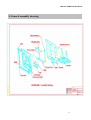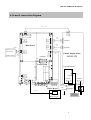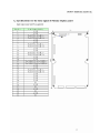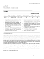
1
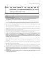
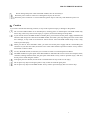
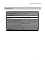
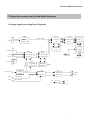
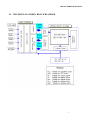
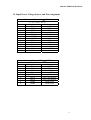
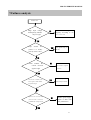
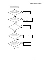
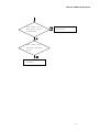
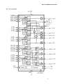
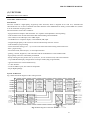
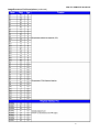
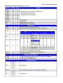
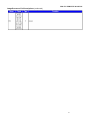
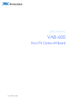
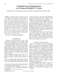
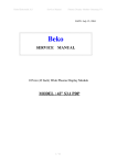
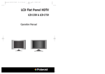
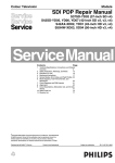
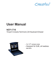
42” Plasma Color Television
Model: PLA-4200M
Service Manual
PDP TV SERVICE MANUAL
Contents
1.Safety instruction…………………………….……………2
2.Specification………………………………….……………4
3.Signal processing and system block diagram….…………..5
4.Part list ……………………………….…………………….7
5.General assembly drawing …………….………………...10
6.General connection diagram………………………………11
7.Failures analysis…………………………….………….….15
8.Description of main ICs and components ….……………..19
1
PDP TV SERVICE MANUAL
Notice: This service manual is only read and used by
professionals. The repairman should review the part of
safety precaution before work.
1.Safety instruction
TO PREVENT POSSIBLE DANGER,DAMAGE, AND BODILY HARM, PLEASE CONSIDER
AND OBSERVE ALL CAUTIONS CONTAINED IN THIS PARAGRAPH.
A.Warning
If you don’t consider the following warning before maintenance, it could result in death or serious injury.
(1) The PDP module is controlled by voltage about 350V. If you need to handle the module during operation or just
after power-off, you must take proper precautions against electric shock and never touch the drive circuit
portion and metallic part of PDP module.
The capacitors in the drive circuit portion remain temporarily charged even after the power off. After turning
off the power, you must be sure to wait at least one minute before touching the module. If the remainder of
voltage is strong enough, it could result in electric shock.
(2) Do not use any other power supply voltage than the specified voltage in this product specifications. If you use
deviated power voltage from the specifications, it could result in fire hazard or product failure.
(3) Do not operate or install under the deviated surrounding from the environmental specification such as in
moisture or rain; near water-for example, bath tub, laundry tub, kitchen sink; in a wet basement; or near a
swimming pool; and also near fire or heater for example, near or over radiator heat resistor; or where it is
exposed to direct sunlight; or somewhere like that. If you use the PDP module in places above, it could result in
electric shock, fire hazard or product failure.
(4) If any foreign objects (e.g. water, liquid and metallic chip or dust) entered the PDP module, the power supply
voltage to the PDP module must be turned off immediately. Also never push objects of any kind into the PDP
module as they may touch dangerous voltage point or make short circuits that could result in fire hazard or
electric shock.
(5) If smoke, offensive smell or unusual noise should come from the PDP module, the power supply voltage to the
PDP module must be turned off immediately.
Also, when the PDP screen cannot display any picture after the power-on or during operation, the power
supply must be turned off immediately. Never continue to operate the PDP module under these conditions.
6 Do not disconnect or connect the PDP module’s connector while the power supply is on, or just after power off.
Because the PDP module is operated by high voltage, and the capacitors in drive circuit remain temporarily
changed even after the power is turned off. If you need to disconnect it, you have to wait at least one minute
after power off.
7 Do not disconnect or connect the power connector by wet hands. The voltage of the product may be strong
enough to cause an electric shock..
2
PDP TV SERVICE MANUAL
8
Do not damage the power cable of the PDP module, also do not modify it.
When the power cable or connector is damaged or frayed, do not use it.
When the power connector is covered with dust, please wipe it with a dry cloth before the power on.
Caution
If you don’t consider the following cautions, it may result in personal injury or damage to the product.
Do not set the PDP module on an unstable place, vibrating place or inclined place. The PDP module may
fall or drop, and it may cause serious injury to a person, and serious damage to the product.
If you need to remove the PDP module to another place, you must turn off the power supply and detach the
interface cable and power cable from the PDP module, and watch your steps during the work. If the cable
has a damage, it may result in fire hazard or electric shock. Also if the PDP module drop or fall, it may
result in personal injury.
When you draw or insert the PDP’s cable, you must turn off the power supply and do it with holding the
connector. If you draw the cable, the electric wire in the cable could be exposed or broken. It may result in
fire hazard or electric shock.
To carry the PDP module, it be done by two workers in order to avoid unexpected accidents.
The PDP module has a glass-plate. If the PDP module is inflicted with excessive stress for example; shock,
vibration, bending and heat-shock, the glass plate could break. It may result in personal injury. And also,
do not press or strike the glass surface.
If the glass plate was broken, do not touch it with bare hand. It may result in a cut injury.
Do not place any object on the glass plate. It may scratch or break the glass plate.
Do not place any object on the PDP module. It may result in personal injury due to its fall or drop.
3
PDP TV SERVICE MANUAL
2.Specifications
Type
System of the broadcasting
System of the video signal
Number of stored programs
Scope of the channel
Signal intensity
Audio input
Speaker output
Visual angle (Max)
Resolution
Power supply
Energy consumption
Dimensions (W*H*D)
Size of screen
Aspect ration
Weight
Ambient temperature
Ambient humidity
Ambient air pressure
PLA-4200M
NTSC-M
PAL/NTSC/SECAM
125
Air: CH2 to CH69,
Cable: CATV1 to CATV125
70dB
Input impedance>10k ,
Input voltage 0.1-0.5 V(rms)
2*5W
160
852*480
AC 100V-240V (50Hz/60Hz)
350W(typ).3W (stand by)
46.1*29.1*5.2 inch
42 inch
16:9
110 lb.
0-35
20%-70%RH
86-106Kpa
4
PDP TV SERVICE MANUAL
3.Signal processing and system block diagram
A. Image signal processing block diagram
U202
J201
RGBHV
VGA IN
U101
U531
Digital RGB
AD9883A
PW166B
Y
UV
A/D Convertor
R(0,7)
G(0,7) THC63LVD823
B(0,7)
LVDS
scale
PDP
Panel
U31
SST39VF800A
J4
S-VHS IN
U301
U302
J3
Y
V1 IN
PW1230
VPC3230
UV
Decoder
V2 IN
AC Card
De-interlace
+5V +9V +12V
VIDEO OUT
YCbCr IN
J2
TCPN9082DC
Cable/air IN
SAMP
Flash
27D(T)
TUNER
A1 IN
EXT Audio IN
A2 IN
EXT Audio IN
U1
Zilog Z86229
CCD V-Chip
MEMORY
BUFFER
U303
U4
U3
MSP 3450G
MTS Process
TDA8944
Speaker
Audio Amp
Speaker
+5V
+12V
DC/DC
+3..3V
5
PDP TV SERVICE MANUAL
B. PDP DISPLAY SCREEN BLOCK DIAGRAM
6
PDP TV SERVICE MANUAL
4.Part list
Part Number
Description
A904008
Polaroid PLA-4200M Plasma Display Panel
Included in A904008
Polaroid PLA-4200M Cable L=150mm
Polaroid PLA-4200M YPbPr Circuit Board
Polaroid PLA-4200M Remote Control Circuit Board
Polaroid PLA-4200M Zinnia PDP Control Circuit Board
SPW5.069.166
SPW5.969.003
A920008
B135011
SPW8.339.008
E143221JF
E143222JH
E143461
E143463
E144231
E144431
E690220
E690221
E690223
E690230
E690420
E690660
E690670
S070183
G330170
Qty.
1
1
1
1
1
8
1
2
6
16
6
30
3
16
6
15
2
14
10
4
1
1
Polaroid PLA-4200M Main Power Button
Polaroid PLA-4200M Tapping Screw ST3*8F
Polaroid PLA-4200M Tapping Screw ST3*8 (black)
Polaroid PLA-4200M Tapping Screw ST4*16
Polaroid PLA-4200M Tapping Screw ST4*16 (black)
Polaroid PLA-4200M Tapping Screw ST3*10
Polaroid PLA-4200M Tapping Screw ST4*10
Polaroid PLA-4200M SEMS Screw M3*8
Polaroid PLA-4200M SEMS Screw M3*8 (black)
Polaroid PLA-4200M SEMS Screw M3*8 (black)
Polaroid PLA-4200M SEMS Screw M3*10
Polaroid PLA-4200M SEMS Screw M4*8
Polaroid PLA-4200M SEMS Screw M6*16 (black)
Polaroid PLA-4200M SEMS Screw M6*20 (black)
Polaroid PLA-4200M Power Switch KDC-A04-1
Polaroid PLA-4200M Remote Control
7
PDP TV SERVICE MANUAL
4.Part list
This page left intentionally blank.
8
PDP TV SERVICE MANUAL
4.Part list
This page left intentionally blank.
9
PDP TV SERVICE MANUAL
5.General assembly drawing
10
PDP TV SERVICE MANUAL
6.General connection diagram
W2
7-31
J5 (LVDS 1/F)
1
LA03
13
W4
2-13
31
J1
Power
CN
(TTL 1/F)
CON8011
1
Main board
9
J2
Power
X1001
1
CON8009
1
W3
Receiving Unit for
Remote control
SPW.5.969.003
W5
1-9
15
W17
6-15
CN6
(OSD)
J7
6
1
Plasma Display Panel
4-6
J6
Connector
S42SD-YD
CN1
CN2
Tuner board
Power filter board
5-3
CN6
(DV1)
12
CN8702
J8
CN8701
1
CON8002
Right
SWITCH 5-3
Speaker
YPbPr Board
3-12
YPbPr Socket
Left
9-1
Speaker
220V~IN
16-1
SPW5.069.166
Power supply socket
11
PDP TV SERVICE MANUAL
B. Input Power Voltage Source and Pin Assignment
Connector Name: SA J1(W4)
to The Image Board
Pin no
Voltage Source
Usage
1
5Vsb
Vcc5-SB-PDP
2
GND
GND
3
GND-D
GND
4
B5d1
NC
5
RELAY
PDP-RELAY
6
TH-DET
NC
7
FAN-DET
NC
8
GND-A
GND
9
GND-A
GND
10
NC
NC
11
V12A
NC
12
V5a
Vcc5-PDP
13
NC
NC
Connector Name: AUDIO J2(W5)
to The Audio Amp Board
Pin no
Voltage Source
Usage
1
V5A
Vcc5-PDP
2
GND-A
GND
3
12VCC
Vcc12-FAN
4
V9A
Vcc9-PDP
5
GND-A
GND
6
24Vsp
Vcc12-AUD-PDP
7
24Vsp
Vcc12-AUD-PDP
8
GNDS
GND-AUD
9
GNDS
GND-AUD
13
PDP TV SERVICE MANUAL
Connector Name:
OSD(W17)
Pin no
Usage
1
2
3
4
5
6
7
8
9
10
11
12
13
14
15
Vcc5
KPAD0
KPAD1
KPAD2
KPAD3
LED-RED
LED-GREEN
Vcc5-SB
GND
POWER-SW
IR
KPAD4
KPAD5
KPAD6
KPAD7
Connector Name:
SPEAKER(W3)
Pin no
Usage
1
2
3
4
5
6
SPEAKER-SW
SPK-OUT1SPK-OUT1+
GND
SPK-OUT2SPK-OUT2+
14
PDP TV SERVICE MANUAL
7.Failures analysis
Without raster
Judge input voltage
input
and frequency whether
frequency according to the
whether
voltage
specification
they are right
Judge
the
this
product is in standby
Press power key to
turn on
mode by remote control
Check
whether
current
the
received
signal is right
Check the
external signal
source
Turn off for 2 minutes, then
if it is ok, maybe failure
turn on again to check whether
results from poor contact
the picture emerges
Open the rear cover then enter
Replace power supply
power-on mode to check the
switch or filter with
CON8002-220v voltage of PDP
poor performance
15
and
PDP TV SERVICE MANUAL
Check the output voltage
Check
and
repair
CON8011 / CON8009 of
display screen power
power board
board voltage
Check the input voltage J1
Check and transpose the
/ J3 connector
line of connector
of main
board
Check the supply voltages of
Check
mainboard:Vcc5-SUB(IC-U
U15-1.#IN , D1,CE21,CE26.
15-4#),Vcc3(IC-U8-2#)
U8-2#IN, C198, CE33.
OR
transpose
Check or transpose
the signal data line
of connector
check and transpose the main
board
check the driver board of PDP
display screen, and the slices
of soft IC etc.
Check the other circuits
16
PDP TV SERVICE MANUAL
Display image but without sound
Turn
on
to
check
exchange tuner board
whether there is noise
Read
Check
whether
the
volume is correctly set
the
operating
instruction, and set the
volume again
Check J7 waveform
Check
of Speaker's audio
speaker
and
exchange
output
Check IC U4 whether
input or output signal
Check and exchange
IC U4
is ok.
Check IC U3 Whether
Check and exchange
input-60#/output-27#
U3
IC
28# signal is OK
17
PDP TV SERVICE MANUAL
Check
whether
there
is
audio output in connector
Check and exchange the connector
which is not good.
CN1/CN2- 40#pin
Check
whether
there
is
audio output in tuner board
(U5-14#)
Exchange the tuner board
or the tuner.
18
PDP TV SERVICE MANUAL
8.Description of main ICs and components
(1) M52790SP/FP
AV SWITCH with I2C BUS CONTROL
DESCRIPTION
The M52790 is AV switch semiconductor integrated
circuit with I2C bus control .
This IC contains 2-channels of 4-input audio switches and
2-channels of 4-input video switches. Each channel can be
controled independently .
The video switches contain amplifiers can be controled a
gain of
output 0dB or 6dB .
FEATURES
•Video and stereo sound switches in one package
•Wide frequency range (video switch) ...........DC-20MHz
•High separation ( video switch ).................Crosstalk
-60dB ( typ. ) at 1MHz
•Two types of packages are provided : SDIP with a lead
pitch of 1.778mm ( M52790SP ) ; and SSOP with a lead
pitch of 0.8mm ( M52790FP ) .
APPLICATION
Video equipment
RECOMMENDED
CONDITION
OPERATING
Supply voltage 4.7V ~ 9.3V
Rated supply voltage 5V,9V
Maximum output current 63mA(at 9V)
19
PDP TV SERVICE MANUAL
20
PDP TV SERVICE MANUAL
(2) MSP3450G
Multistandard Sound Processor Family
Release Note: Revision bars indicate significant changes to the previous edition. The hardware and software
description in this document is valid for the MSP 3450G version B5 and following versions.
Introduction
The MSP 3450G family of single-chip Multistandard Sound Processors covers the sound processing of all analog
TV-Standards worldwide, as well as the NICAM digital sound standards. The full TV sound processing, starting with
analog sound IF signal-in, down to processed analog AF-out, is performed on a single chip. Figure4 shows a
simplified functional block diagram of the MSP 3450G.
This new generation of TV sound processing ICs now includes versions for processing the multichannel television
sound (MTS) signal conforming to the standard recommended by the Broadcast Television Systems Committee
(BTSC). The DBX noise reduction, or alternatively, MICRONAS Noise Reduction (MNR) is performed alignment
free.
Other processed standards are the Japanese FM-FM multiplex standard (EIA-J) and the FM Stereo Radio standard.
Current ICs have to perform adjustment procedures in order to achieve good stereo separation for BTSC and EIA-J.
The MSP 3450G has optimum stereo performance without any adjustments.
All MSP 3450G versions are pin and software downward-compatible to the MSP 3450D. The MSP 34x0G further
simplifies controlling software. Standard selection requires a single I2C transmission only.
The MSP 34x0G has built-in automatic functions: The IC is able to detect the actual sound standard automatically
(Automatic Standard Detection). Furthermore, pilot levels and identification signals can be evaluated internally with
subsequent switching between mono/ stereo/bilingual; no I2C interaction is necessary (Automatic Sound Selection).
The ICs are produced in submicron CMOS technology. The MSP 34x0G is available in the following packages:
PLCC68, PSDIP64, PSDIP52, PQFP80, and PLQFP64.
Fig. 4: Simplified functional block diagram of the MSP 3450G
21
PDP TV SERVICE MANUAL
(3) VPC323OD
PRELIMINARY DATA SHEET
Comb Filter Video Processor
Introduction
The VPC 3230D is a high-quality, single-chip video front-end, which is targeted for 4:3 and 16:9, 50/60-Hz and
100/120 Hz TV sets. It can be combined with other members of the DIGIT3000 IC family (such as DDP 331x) and/or
it can be used with 3rd-party products.
The main features of the VPC 3230D are
– high-performance adaptive 4H comb filter Y/C separator with adjustable vertical peaking
– multi-standard color decoder PAL/NTSC/SECAM including all substandards
– four CVBS, one S-VHS input, one CVBS output
– two RGB/YCrCb component inputs, one Fast Blank (FB) input
– integrated high-quality A/D converters and associated clamp and AGC circuits
– multi-standard sync processing
– linear horizontal scaling (0.25 ... 4), as well as non-linear horizontal scaling ‘Panoramavision’
– PAL+ preprocessing
– line-locked clock, data and sync, or 656-output interface
– peaking, contrast, brightness, color saturation and tint for RGB/YCrCb and CVBS/S-VHS
– high-quality soft mixer controlled by Fast Blank
– PIP processing for four picture sizes (1/4,1/9,1/16, or1/36 of normal size) with 8-bit resolution
– 15 predefined PIP display configurations and expert mode (fully programmable)
– control interface for external field memory
– I2C-bus interface
– one 20.25-MHz crystal, few external components
– 80-pin PQFP package
System Architecture
Fig.5 shows the block diagram of the video processor
Fig. 5: Block diagram of the VPC 3230D
22
PDP TV SERVICE MANUAL
Pin Configuration
Fig.6: 80-pin PQFP package
23
PDP TV SERVICE MANUAL
(4) Z86229
NTSC LINE 21 CCD DECODER
GENERAL DESCRIPTION
Capable of processing Vertical Blanking Interval (VBI) data from both fields of the video frame in data, the
Z86229 Line 21 Decoder offers a feature-rich solution for any television or set-top application. The robust nature
of the Z86229 helps the device conformto the transmission format defined in the Television Decoder Circuits
Act of 1990, and in accordance with the Electronics Industry Association specification 608 (EIA–608).
The Line 21 data streamcan consistof data fromseveral data channels multiplexed together. Field 1 consists of
four data channels: two Captions and two Texts. Field 2 consists of five additional data channels: two Captions,
two Texts, and Extended Data Services (XDS). The XDS data structure is defined in EIA–608. The Z86229 can
recover and display data transmitted on any of these nine data channels.
The Z86229 can recover and output to a host processor via the I2C serial bus. The recovered XDS data packet is
further defined in the EIA–608 specification. The on-chip XDS filters in the Z86229 are fully programmable,
enabling recovery of only thoseXDSdata packets selected by the user. This functionality allows the device to
extract the required XDS information with proper XDS filter setup for compatibility in a variety of TVs, VCRs,
and Set-Top boxes.
In addition, the Z86229 is ideally suited to monitor Line 21 video displayed in a PiP window for violence
blocking, CCD, and other XDS data services.
24
PDP TV SERVICE MANUAL
25
PDP TV SERVICE MANUAL
(5) HY57V641620HG
DRAM
26
PDP TV SERVICE MANUAL
27
PDP TV SERVICE MANUAL
(6) TDA8944J
STEREO AUDIO AMPLIFIER
28
PDP TV SERVICE MANUAL
Fig 9. Block diagram
29
PDP TV SERVICE MANUAL
(7) PW166 ImageProcessor
XGA/SXGA Flat Panel Display Controller IC
30
PDP TV SERVICE MANUAL
Fig11.PW166 Pin Diagram - Top View
31
PDP TV SERVICE MANUAL
ImageProcessor Pin Descriptions
32
PDP TV SERVICE MANUAL
ImageProcessor Pin Descriptions (continued)
33
PDP TV SERVICE MANUAL
ImageProcessor Pin Descriptions (continued)
34
PDP TV SERVICE MANUAL
ImageProcessor Pin Descriptions (continued)
35
PDP TV SERVICE MANUAL
ImageProcessor Pin Descriptions (continued)
36
PDP TV SERVICE MANUAL
ImageProcessor Pin Descriptions (continued)
37
PDP TV SERVICE MANUAL
ImageProcessor Pin Descriptions (continued)
38