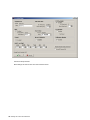
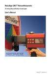
1
On site quality verification of road signs User’s Manual DELTA Danish Electronics, Light & Acoustics Venlighedsvej 4 · 2970 Hørsholm · Denmark Tel. (+45) 72 19 40 00 · Fax (+45) 72 19 40 01 RetroSign GR1 & GR3 · Retroreflectometer 1 DISCLAIMER The information contained in this document is subject to change without notice. DELTA MAKES NO WARRANTY OF ANY KIND WITH REGARD TO THIS MATERIAL, INCLUDING, BUT NOT LIMITED TO, THE IMPLIED WARRANTIES OF MERCHANTIABILITY AND FITNESS FOR A PARTICULAR PURPOSE. DELTA SHALL NOT BE LIABLE FOR ERRORS CONTAINED HEREIN OR FOR INCIDENTAL OR CONSEQUENTIAL DAMAGES IN CONNECTION WITH THE FURNISHING, PERFORMANCE OR USE OF THIS MATERIAL. Caution: Changes / modifications not approved by the responsible party could void the user’s authority to operate the equipment. NOTE: This equipment has been tested and found to comply with the limits for a Class A digital device, pursuant to part 15 of the FCC Rules. These limits are designed to provide reasonable protection against harmful interference when the equipment is operated in a commercial environment. This equipment generates, uses, and can radiate radio frequency energy and, if not installed and used in accordance with the instruction manual, may cause harmful interference to radio communications. Operation of this equipment in a residential area is likely to cause harmful interference in which case the user will be required to correct the interference at own expense. RF Exposure compliance statement: This device incorporates a certified Bluetooth module, FCC ID: S7APARANIESD200, which may be used in portable exposure conditions with no restrictions on host platforms, since the source-based time-averaged output power is ≤ 60/f(GHz) mW.. Rev.: 15 August 2012 2 RetroSign GR1 & GR3 · Retroreflectometer RetroSign GR1 & GR3 · Retroreflectometer 3 4 RetroSign GR1 & GR3 · Retroreflectometer Index Section 1 – Introduction .................................................................................... 7 RetroSign introduction ....................................................................................... 7 RetroSign Retroreflectometer features .............................................................. 8 Options .............................................................................................................. 8 Section 2 – Operating Information .................................................................... 9 Getting started ................................................................................................... 9 Icons .................................................................................................................. 9 Perform a measurement .................................................................................. 10 Sequence ID .................................................................................................... 10 Keyboard functions .......................................................................................... 10 Calibration........................................................................................................ 11 Menu system ................................................................................................... 12 Battery / charging ............................................................................................. 14 Remote control ................................................................................................ 14 Support flange ................................................................................................. 15 Aperture reduction ........................................................................................... 15 Section 3 – General Information ..................................................................... 16 RetroSign GR1 & GR3 ..................................................................................... 16 Factory calibrations .......................................................................................... 16 Measurement geometry ................................................................................... 16 GR1 and GR3 type ASTM ............................................................................... 16 GR3 type CEN ................................................................................................. 17 GR1 type SAFETY ........................................................................................... 17 Battery ............................................................................................................. 17 Note on error sources ...................................................................................... 18 Section 4 – Maintenance.................................................................................. 19 General care .................................................................................................... 19 Front lens ......................................................................................................... 19 Battery & Battery charger................................................................................. 19 Lamp ................................................................................................................ 20 Reference cap ................................................................................................. 21 Calibration........................................................................................................ 21 APPENDIX A ........................................................................................................... 22 COMMUNICATION FACILITIES ...................................................................... 22 APPENDIX B ....................................................................................................... 23 Specifications ..................................................................................................... 23 General characteristics .................................................................................... 23 Environmental characteristics .......................................................................... 24 Mechanical characteristics ............................................................................... 24 APPENDIX C ....................................................................................................... 26 Carrying case content........................................................................................ 26 APPENDIX D ....................................................................................................... 27 Communication Facilities .................................................................................. 27 RetroSign GR1 & GR3 · Retroreflectometer 5 USB specification ............................................................................................. 27 Bluetooth specification ..................................................................................... 27 APPENDIX E ....................................................................................................... 29 Quick Guide for RetroSign Extension Kit ........................................................ 29 Preparation ...................................................................................................... 29 Precation.......................................................................................................... 29 Operation ......................................................................................................... 29 Operation with the RFID or Barcode Reader option ........................................ 29 Important.......................................................................................................... 30 APPENDIX F ........................................................................................................ 31 GPS Implementation ........................................................................................ 31 Controlling the GPS function from the menu system ....................................... 32 APPENDIX G ....................................................................................................... 33 TAG Readers ...................................................................................................... 33 RFID implementation ....................................................................................... 33 RFID spec. ....................................................................................................... 33 Barcode Reader Implementation ..................................................................... 34 Barcode Reader spec. ..................................................................................... 34 APPENDIX H ....................................................................................................... 35 Result and Info Pages (examples) .................................................................... 35 APPENDIX J ........................................................................................................ 37 RSC for RetroSign GR1 & GR3 ......................................................................... 37 RSC-GR3 Log Report example: ...................................................................... 39 APPENDIX K ....................................................................................................... 41 * Using the Bluetooth option .............................................................................. 41 Using the Bluetooth link to do measurements.................................................. 41 Commands that can be used on the BT connection ........................................ 42 6 RetroSign GR1 & GR3 · Retroreflectometer Section 1 – Introduction RetroSign introduction The RetroSign retroreflectometer is a portable field instrument intended for measuring the retroreflection properties of road signs in car headlight illumination. The value RA (coefficient of retroreflected luminance) is used for the measurement. RA is a measure of the visibility of the road signs as seen by drivers of motorized vehicles in headlight illumination. The RetroSign is available in different versions. For type GR3 ASTM the sign is illuminated at an entrance angle of -4º and the measurements are made with angles between illumination and observation of 0.2º, 0.5º and 1.0º. This is relevant for a motorist viewing situation under normal conditions. For type GR3 CEN the sign is illuminated at an entrance angle of +5º and the measurements are made with angles between illumination and observation of 0.33º, 0.5º and 1.0º. This is relevant for a motorist viewing situation under normal driving conditions. For type GR1 SAFETY the measurement area is illuminated at an entrance angle of +5º and the measurements are made with an observation angle of 0.2º, angles used to measure Safety Clothing according to EN 471 The ASTM and CEN type instruments is also offered in a GR1 version with only the primary observation angles of 0.2º (ASTM) and 0.33º (CEN). The range of RetroSign instruments available are summarized below: ASTM CEN Safety RetroSign GR1 √ √ √ RetroSign GR3 √ √ ASTM E 1709 EN 12899-1 Geometry 1 primary observation angle 3 observation angles EN 471 RA is an important factor in the onsite quality control of road signs. DELTA RetroSign Retroreflectometer. The operation of the Retroreflectometer is very simple and requires a minimum of instruction. An error or warning message is given in case of unreliable or measurement. RetroSign GR1 & GR3 · Retroreflectometer 7 The RetroSign measures the retroreflection and calculates RA according to international standards. Results are presented on an LCD panel. Each measurement can be marked with a user defined name (measurement ID) of up to 12 alphanumeric characters and an auto incrementing sequence number. The memory provides on-site registration of measurements with corresponding date, time, ID, measurement status, GPS position (optional) and TAG code (optional). The GR1 or GR3 is equipped with a USB port that gives easy PC access to measurement data and diagnostics. The RetroSign is powered by a rechargeable battery, offering many hours of measurement capacity. A mains powered battery charger is supplied as standard. RetroSign Retroreflectometer features Portable instrument Measurement in full daylight Photopic corrected detector and source »A« Automatic stray light compensation and error diagnostics Measurement geometry and illumination corresponding to realistic viewing condition in night time traffic Direct digital read out Easy calibration procedure Reference cap for calibration Real time clock Automatic data storage in non-volatile memory Automatic programmable power off function USB port providing easy communication for data transfer, extended control and diagnostics Long lifetime battery 230 V/ 50 Hz or 120V/60 Hz mains powered battery charger Small support flange with cross hair Aperture reducer Ø15 mm (0.60 in) USB cable Shoulder strap Carrying case Options Extension pole kit with remote trigger, display and large support flange. Advanced 16 channel GPS receiver Barcode reader for measurement documentation RFID (Radio Frequency ID) tag reader, for measurement documentation using wireless smart tags Bluetooth (wireless communication link) for wireless data and control Extra Battery. Aperture Reducer Ø10 mm (0.40 in) 8 RetroSign GR1 & GR3 · Retroreflectometer Section 2 – Operating Information Getting started Turn the RetroSign on by pressing ON/C. After approx. 2 seconds the display will show: Calibrate the instrument if necessary, See calibration section. Icons Instrument status and operational mode are signaled by the use of icons. Icons are shown in the top line of the display. Instrument is calibrated and ready. Menu selected. Calibration selected Zero calibration in progress. Reference calibration in progress. Calibration monitor active for normal aperture Calibration monitor disable for reduced aperture Battery fully charged Battery getting low Battery discharged, measurement not possible GPS position fix, (strikeout if no fix) Display backlight is on. Σ Mean calculation enabled Tag reader option installed and enabled (optional) Bluetooth option enabled and connected (optional) Bluetooth option enabled but not connected (optional) When is shown the instrument is calibrated and ready for use. RetroSign GR1 & GR3 · Retroreflectometer 9 Perform a measurement Place the instrument front on the surface to measure. Start the measurement by pressing the red trigger knob on the handle. The display shows WAIT for the duration of the measurement, approx. 2 seconds. A sound (1 signal the end of the measurement and the result is displayed together with other relevant information. If errors or warning conditions are detected during the measurement sequence, this will be shown as “Err” or “Warn” together with the result. Sequence ID The RetroSign has a built in function to mark each measurement with a user defined name (Sequence ID) and a unique (2 Sequence Number automatically generated by the instrument. The Sequence ID and the Sequence Number will also be stored in the log. The maximum length of the Sequence ID text is 12 alphanumeric characters. 1) The sound generation has to be turned on in the menu 2) The Sequence number can be edited from the menu. Keyboard functions Keyboard layout Trigger on handle Push shortly to switch on the instrument. Redisplay the last measurement result. Clear the mean calculation when displayed Cancellation of current menu operation. Turn Instrument Off. Changed settings will be stored Select menu items Scroll keys when in menus Parameter and value increment (+) / decrement (-) Start instrument calibration function Select / change settings in menus Switch between result and status displays Activate selected functions Start R’ measurement. Select quick calibration mode. Select next calibration step Read RFID/Barcode tag when mounted and enabled 10 RetroSign GR1 & GR3 · Retroreflectometer Calibration RetroSign features two levels of calibration: Quick and Full. Quick calibration is an “everyday” calibration using zero results and reference values from the latest full calibration. This option may only be used with the same reference unit that was used for the full calibration. Full calibration is used for high accuracy calibration of zero and reference. Quick calibration Quick calibration is initiated by pressing the button and then the trigger. Mount the reference cap (reflective side) before triggering. The display shows WAIT and the Calibration is executed immediately using previous defined reference values. If the calibration fails, the display shows a short warning message saying that the old calibration values will be used; a status flag will be set and logged for this condition. Full calibration Full calibration is initiated by pressing the button and then. Follow the displayed procedure. Zero Mount the zero cap (dark side) on the instrument. Press the or the trigger when ready. The display shows WAIT while measuring and then shortly displays the measured zero values. If the measured values are ok the instrument is ready for the next step in the calibration procedure. If high zero values are measured, a warning text will be shown and the user asked to check the black target and try again. Reference Mount the reference cap (reflective side). If necessary edit the displayed reference value using matches the value printed on the reference unit, press or until it or the trigger to advance to the next reference value. When all reference values has been checked and edited the instrument executes the calibration process. WAIT is displayed during the actual calibration measurement and then the calculated calibration factors are shortly displayed. If errors are detected during the calibration process a warning text is displayed and the user is asked to check the white target and retry the calibration by pressing or the trigger again. The reference values will not need to be checked again. When the calibration is successful, continue by pressing After a successful calibration the , or the trigger. icon is shown and the instrument is ready for measurements. It is good practice to do a measurement on the calibration unit immediately after the calibration to check the values. Reduced aperture option When the instrument is configured for measurements with reduced aperture the calibration monitor should be disabled. This changes the checking of the calculated calibration values and displays the icon to alert the user that this op- tion has been selected. The instrument must be recalibrated whenever this function is enabled or disabled. See also paragraph Aperture Reduction in this section for further information. RetroSign GR1 & GR3 · Retroreflectometer 11 Menu system General menu operations: When in measurement mode pressing or activates the menu system. When in menu mode, use the to scroll through the functions or to change values. Press menus the Pressing Use and to select or accept the displayed function or value. In some key is used to switch between different selections. terminates the menu and switches back to the results display. to scroll through the menu list as shown below, using reverses the list. Menu items: Sequence ID: (Measurement ID) A measurement series can be assigned a unique ID that is logged together with the results. Each measurement made with the ID is also assigned a sequence number that automatically increments by one for each measurement. The Sequence ID is shown as Seq ID[string] where string can be up to 12 alphanumeric characters, e.g. [CARLANE 1 XY] To edit the sequence ID press . The display changes to show the defined ID and a line showing the new ID. To a start the new ID will be identical to the old ID. Underneath the new ID the edit position is marked with an up-arrow symbol. Use the edit keys to make changes to the marked position. When defining a new ID, the sequence number will be reset to zero. ID Count: (Display ID count for edit) The auto incremented Sequence ID number can be changed, use the normal edit keys to change the value. Clear ID: (Set Sequence ID to undefined) The display shows the defined sequence ID, the ID can be set to undefined using the edit keys. Use this option to completely remove the ID string. Clear Work Log: (Set user log record counter to zero) The display shows the number of records in the work log. This function allows the user to reset the log record counter. The function can be used when starting a new measurement series without first reading the records already in the log. It should be emphasized that no data actually is erased by this operation; it is merely the presentation of the number of new records in the log that changes, and it should also be emphasized that all old data records can still be read out at a later time. Normally this counter will be reset by the PC program after reading the data to a file. Sound Control: (Control generation of system sounds) This function controls how the instrument uses sounds to report different conditions, e.g. the end of a measurement cycle, error conditions etc. Setting this control to off completely silences the instrument. 12 RetroSign GR1 & GR3 · Retroreflectometer Off Timer: (Power Saver) This function controls how long the instrument stays ON when not used. This function is to preserve power before powering off. Changed values and setting will be saved, and selecting a value less than 60 seconds will disable this function. Mean Calculation: (Calculate and display mean values) The Mean values are calculated and displayed together with the number of measurements used for the calculation. Shift to main display screen #2 (see appendix F) by pressing to see the calculated values. In display line 2 the value MC= shows the number of measurements used to calculate the mean value. See appendix F The display shows both the measured value (raw) and the calculated value (mean) When in the main display screen #2 press two times to clear the mean calculation. Enabling this function affects the way the Tag Reader function works. See appendix E Calibration Monitor: (Calibration factor monitor) The build in calibration monitor is used to check the calculated calibration factors against minimum and maximum limits, it can be disabled; this should be done when using the aperture reducer’s as this can result in factors outside the normal limits, marking the measurements with a calibration warning. The normal limit checking is designed to be a safeguard against errors in the calibration procedure. When the Monitor is enabled the icon displays, when disabled the icon displays. IMPORTANT: the instrument must be recalibrated whenever changing form normal to reduced aperture and vice versa. Remote-Box Display: (Select result for extender box display) The remote trigger can only display one result at a time, this function selects which result to display on the remote trigger unit. The normal setting would be the primary observation angle of 0.2º or 0.33º Display Backlight: (Control LCD backlight) The automatic LCD display backlight function can be disabled. Doing so will allow for more measurements on the same battery charge, as backlighting consumes lots of energy. DGPS Mode: (Select GPS position correction method) (Optional) The GPS receiver can use different methods to obtain greater position precision by using different correction signal sources. Depending on the location, different systems can be selected: WAAS should be used in North America. EGNOS should be used in Europe. Auto: should select the best possible available correction signal. However, not all systems may be fully operational or they may be in test modes. Selecting a wrong correction system might actually reduce the precision. Disable: Don’t use any correction signals. RetroSign GR1 & GR3 · Retroreflectometer 13 GPS State: (Control the GPS function) (Optional) The GPS receiver can be disabled if desired, the main reason for doing this would be to reduce the overall power consumption maximizing the number of possible measurements on the available battery charge. Tag Reader: (Control the RFID or Barcode reader option) (Optional) The GR1 and GR3 have an option for inputting data from an external RFID or Barcode reader. This will make it possible to use RFID tags or standard Barcodes to uniquely identify signs. Enabling the reader option changes the way the instrument behave when taking measurements. When no reader is connected this option must be disabled When enabled, the instrument will ask for a Tag on the first trigger. When the tag has been read the instrument will do the measurement on the second trigger. See appendix E When the Mean Calculation is enabled the instrument will only ask for the tag on the first measurement in a series (Mean Count < 2). This allows for doing multipoint measurements with the same Tag code. After clearing the mean calculation the instrument will again ask for the Tag on the first trigger. Remove Latest Measurement: (undo the most recent measurement) It is possible to remove the most recent measurement record from the work log. To maintain data integrity only one data record can be removed and only if it is done before the instrument is turned off. Battery / charging Never disconnect the battery while the instrument is turned on as this may result in lost data and malfunction of the instrument. Temperatures in excess of 50º C (122º F) under operation will damage the battery. Do not short circuit the battery. Do not dispose with household waste. To remove the battery swing the battery retaining spring over, and disengage the battery from the handle. See Section 4 - Battery for further information on charging. THE BATTERY SUPPLIED WITH RETROSIGN IS SPECIALLY DESIGNED FOR THE INSTRUMENT TO ENSURE SAFE USE. IF A NON DELTA SUPPLIED OR APPROVED BATTERY IS USED WITH RETROSIGN DELTA CAN TAKE NO RESPONSIBILITY FOR ANY DAMAGED CAUSED DUE TO THE PERFORMANCE OF THIS BATTERY. Remote control External trigger option (Optional) By connecting a remote trigger box to the rear connector on the instrument it is possible to do measurements using an extension pole. As an accessory an Extension pole kit can be supplied. 14 RetroSign GR1 & GR3 · Retroreflectometer Computer interface The instrument is equipped with a device USB port; this allows complete remote instrument control and measurement data collection. Use the Road Sensor Control (RSC) software to offload measurement records or to control the RetroSign. Use of the USB connection requires the installation of a special software driver on the PC which can be found on the instrument CD.. See Appendix B - Communication facilities. Support flange The support flange is provided with cross hair markings. It makes it easier to decide the measuring position when taking measurements on small objects, e.g. letters and numbers on a sign. Aperture reduction For special measurement requirements on small targets, the RetroSign can be mounted with a special aperture reducer adaptor; this reduces the field of measurement to either ø 15 mm (0.6 in) or ø 10 mm (0.4 in) depending on the unit used. The ø 15 mm is supplied with the RetroSign while the Ø 10 mm is optional. To achieve the smaller aperture, the reduction unit is simply mounted in front of the lens barrel. Disable the Calibration Monitor when using the Reducer! See Menu Items on how to disable the monitor. IMPORTANT! Remember always to calibrate the instrument after changing the aperture setting. Note: RetroSign is an optical precision instrument, handle with care. Store in clean and dry environment. Do not recharge after using the instrument only briefly. Never remove the battery when the instrument is ON Carefully check and clean the reference cap, the reading is very sensitive to contamination. RetroSign GR1 & GR3 · Retroreflectometer 15 Section 3 – General Information RetroSign GR1 & GR3 The RetroSign Retroreflectometer measures the RA (coefficient of retroreflected luminance) parameter. The R’ parameter represents the retroreflection of the road signs seen by drivers of motor vehicles by headlight illumination. Physically the Retroreflectometer is a small hand held instrument. It is constructed in aluminum housing, containing electronics and an optical system. The measurement trigger button and the replaceable battery are housed in the handle. The RetroSign is controlled by a micro controller that executes a measurement automatically when the trigger is activated. The result and status are shown on the LCD display. The result and other related information is automatically transferred to the internal non-volatile memory. The RetroSign is operated from a small keyboard on the left hand side of the Retroreflectometer. The Retroreflectometer control is also possible using a USB device connection. The USB connection is used to transfer data records to a PC for further processing. Factory calibrations The RetroSign GR1 and GR3 is factory calibrated. This calibration is carried out using a standard. The reference’s RA value is measured in the laboratory using traceable methods and equipment. The enclosed reference cap should be used for verification and recalibration of the Retroreflectometer. Measurement geometry GR1 and GR3 type ASTM The illumination angle is -4°. The offsets between the illumination and the primary observation angle are 0.2° (GR1) and the three observation angles are 0.2°, 0.5°and 1.0° (GR3) respectively. The measurement area is approx. ø 30 mm. in the standard configuration, ø 15 mm or ø 10 mm when using the reduced aperture adaptors. ASTM geometry 16 RetroSign GR1 & GR3 · Retroreflectometer GR3 type CEN The illumination angle is +5°. The offsets between the illumination and the primary observation angle are 0.33° (GR1) and the three observation angles are 0.33°, 0.5°and 1.0° (GR3) respectively. The measurement area is approx. ø 30 mm. in the standard configuration, ø 15 mm or ø 10 mm when using the reduced aperture adaptors. CEN geometry GR1 type SAFETY The illumination angle is +5° and the offsets between the illumination and observation angle is 0.2°. The measurement area is approx. ø 30 mm. in the standard configuration, ø 15 mm or ø 10 mm when using the reduced aperture adaptors. Cloth 0.2° CEN EN 471 geometry Battery The RetroSign is powered by a replaceable rechargeable battery, which under normal operation will keep the Retroreflectometer operating for many hours. The battery must be recharged by the included external charger. See Section 4 Battery. RetroSign GR1 & GR3 · Retroreflectometer 17 Note on error sources Before measuring The RetroSign is factory calibrated; nevertheless, begin important measurements sessions with a calibration, dust and smear from touching the optical surfaces might influence the measured values considerably. It is very important to keep the instrument front lens and the white reference cap clean. See also Section 4 - Maintenance. Instrument orientation The RetroSign can take measurements without being in close contact with the sign surface. But to obtain the most reliable results the front of the RetroSign should be in contact with, and perpendicular to, the sign surface when taking measurements. Sign conditions The optical property of a sign alters when the retro reflective material becomes wet. The RetroSign can take measurements on wet or dewy sign surfaces but readings are not comparable with readings taken on dry signs. Because of the special optical properties of micro prismatic sheeting, precautions like turning the instrument correctly and holding it vertical should be taken to get correct readings. Always use the RetroSign in the angle specified for the sign. Normally the RetroSign instrument must be held in the vertical position. Leakage During each measurement the RetroSign automatically evaluates the leakage (optical background signal) and the result are compensated before read out. Leakage will under normal conditions not be significant. Nevertheless, leakage may occur and a warning will be shown in the display. Leakage is primarily caused by stray light entering the optics between the sign and the instrument. Instrument leak, drift and offset errors are compensated for by means of data obtained during the calibration procedure, so perform the calibration procedure carefully. Low battery condition The instrument always monitors the battery voltage and automatically blocks for further measurements when the battery voltage gets very low. Due to the nature of the battery it may happen, when the instrument is turned on, that the voltage will be high enough to start a measurement but not to turn the light source on causing the measurement to fail. Doing measurements with a nearly discharged battery should be avoided as this might influence the measured values. 18 RetroSign GR1 & GR3 · Retroreflectometer Section 4 – Maintenance General care The Retroreflectometer is constructed for outdoor use in fair weather conditions. The Retroreflectometer will withstand moist weather, but caution must be taken against rain or splashes and dirt form traffic. The RetroSign Retroreflectometer is a robust instrument, but it is an optical instrument and must be handled as such. Avoid exposing the instrument to high mechanical shocks and vibrations. Avoid exposing the instrument to rapidly changing temperatures. When not in use store the instrument in the caring case in a clean and dry environment. Front lens The lens does not need special maintenance. If dirty carefully moist the lens with ordinary window cleaning liquid and clean it with a soft linen cloth. Battery & Battery charger The instrument is powered by a NiMh (Nickel Metal Hydride) battery, which under normal use requires no maintenance. The battery used is Sanyo Akku APBO 9,6V, 2600mA (P 217). A battery charger is provided as a standard accessory for charging the battery from mains. The battery charger comes in two models: 230V AC, 50/60 Hz (Bosch AL 2450 Professional) 120V, 60 Hz (Bosch BC 130) The battery will be fully charged in approx. 35 minutes To recharge the battery first make sure that the instrument is off, then release the battery retaining spring, remove the battery from the handle and insert it in the charger. Make sure the battery and battery charger is clean and dry before and during charging takes place. The battery charger will during charging give the following information If the green indicator light is “ON” the charger is plugged in but the battery pack is not inserted , or the battery pack is fully charged and is being trickle charged If the green indicator light is “BLINKING”, the battery pack is being fast-charged. Fast-charging will automatically stop when the battery pack is fully charged If the red indicator light is “ON”, the battery pack is too hot or cold for fast-charging. The charger will switch to trickle charge, until a suitable temperature is reached, at which time the charger will switch automatically to fastcharging If the red indicator light is “BLINKING”, the battery pack cannot accept a charge (the battery may be detective) or the contacts of the charger or battery pack are contaminated. Clean the contacts of the charger or battery pack and check. Change the battery is no solution can be found. A new battery or one which has not been used for an extended period of time will reach full performance only after approximately 5 charging and discharging cycles. The battery is equipped with a temperature monitor that only allows charging within a range between 0C and 45C (32F and 113F). This ensures long battery life. When used properly, the battery can be recharged up to 1000 times. A substantial drop in obtainable measurements on a fully charged battery indicates that the battery is worn out and must be renewed. The Battery and the charger are specifically designed for use in conjunction with one another. Charging should be done only with the charger delivered with the instrument. Do not expose the battery to heat or flames: Danger of explosion. Do not place the battery on a heater or expose to direct sunlight for long periods. Temperatures in excess of 50C (122F) during operation will damage the battery. Allow a warm battery to cool before charging. When handling or storing the battery take special care to avoid possible short circuiting the battery contacts. Avoid repeated consecutive rapid charges of the battery. Do not recharge after using only briefly. RetroSign GR1 & GR3 · Retroreflectometer 19 For your safety, battery charger: Read all instructions. Failure to follow all instructions listed below may result in electrical shock, fire and/or serious injury. Protect the battery from rain and moisture. The penetration of water in a battery charger increases the risk of electric shock Keep the battery charger clean. Contamination may cause the danger of electric shock. Check the battery charger, cable and plug each time before using. Do not use the battery charger when defects are detected. Do not open the battery charger yourself and have it repaired only by qualified personnel using original spare parts. Damaged battery chargers, cables and plugs increase the risk of electric shock. Do not operate the battery charger on easily inflammable surfaces (e.g. paper, textiles, etc.) or combustible environments. There is danger of fire due to the heating of the battery charger during charging Practical advice, battery charger With continuous or several repetitive charging cycles without interruption, the charger can warm up. This is not meaningful and does not indicate a technical defect of the unit Maintenance and cleaning, battery charger The unit is maintenance free. Always keep the unit and the ventilation slots clean Note The battery should be protected against impact. Do not open the battery. Store the battery in a dry and clean place. Due to environmental protection do not dispose the battery with household waste. Lamp The lamp requires no maintenance. At the end of the lamps service life the instrument will display a lamp error message, and the lamp must be replaced. The lamp must be replaced only by DELTA or personal trained by DELTA. 20 RetroSign GR1 & GR3 · Retroreflectometer Reference cap To make sure that the calibration of the Retroreflectometer is correct it is important that the surface on the reference cap is clean and undamaged. Keep the cap protected, and be careful not to touch the reference cap (reflective side). If the surface is stained, scratched, or broken the reference cap must be replaced. In case of dust on the surface, clean the reference cap gently by using a soft cloth with a mild household detergent. Wipe carefully with dry linen cloth afterwards. To ensure reliable measurements, it is recommended that the reference cap is periodically recalibrated to a traceable standard. DELTA Light & Optics offers calibration traceable to PTB (Physikalisch-Technishe Bundesanstalt) and NIST (National Institute of Standards and Technology). For information contact your local distributor or DELTA Light & Optics, Denmark. Reference cap. Calibration The RetroSign is factory calibrated, but a calibration should always be carried out before starting a series of measurements. The calibration process automatically compensates for instrument offsets, leakage and other known “errors” and calculates calibration factors for each observation angle. After a calibration the Retroreflectometer will display »true« RA values. Store the reference cap in a dry and clean environment. RetroSign GR1 & GR3 · Retroreflectometer 21 APPENDIX A COMMUNICATION FACILITIES The RetroSign is at the front equipped with a connection for the tag readers (Barcode, RFID) The RetroSign is at the back equipped with a USB Device Port and a connection to remote control of extension pole. The USB Device Port is used to connect the instrument to a PC. 22 RetroSign GR1 & GR3 · Retroreflectometer APPENDIX B Specifications General characteristics Regulatory compliance EU The equipment complies with the following directives of the European Parliament and of the Council: Directive 1999/5/EC of 9 March 1999 on radio equipment and telecommunications terminal equipment. Directive 2011/65/EU of 8 June 2011 on restriction of the use of certain hazardous substances (RoHS). Directive 2002/96/EC of 27 January 2003 on waste electrical and electronic equipment (WEEE). The equipment is tested to the following standards: R&TTE article 3.1a (health & safety): ..................................................... EN 60950-1:2006 + A11:2009 + A1:2010 + A12:2011 R&TTE article 3.1b (electromagnetic compatibility): ............................... EN 301489-1 V1.8.1:2008 EN 301489-3 V1.4.1:2002 R&TTE article 3.2 (radio parameters): .................................................... EN 300440-2 V1.4.1:2010 USA The equipment complies with the following rule part of the Federal Communications Committee: FCC CFR 47 Part 15 Subpart B, Class A. The equipment incorporates a separately certified Bluetooth radio module, FCC ID: S7APARANIESD200 The equipment complies with the following safety specification: IEC 60950-1:2005 (2 nd Edition); Am 1:2009 Type ASTM Geometry ASTM E-1709 Illumination angle ................................................................................-4° observation angles........................................................... 0.2°, 0.5°, 1.0° Type CEN Geometry CEN EN 12899-1 Illumination angle ...............................................................................+5° observation angles......................................................... 0.33°, 0.5°, 1.0° Type SAFE Geometry CEN EN 471 Illumination angle ...............................................................................+5° observation angle ............................................................................. 0.2° RetroSign GR1 & GR3 · Retroreflectometer 23 Common geometry parameters Light source angular aperture ........................................................... 0.1° Receptor angular aperture ................................................................ 0.1° Field of measurement ....................................................... ø 30mm/1.2in Light source ......................................................................Illuminant »A« Receptor sensitivity.............................................. Precise eye corrected (ASTM-E1709 para. 6.4.2 for selected color filters) Min. reading (cd/lx×m²) ......................................................................... 0 Max reading (cd/lx×m²) ................................................................. 2000 Electrical characteristics Power supply: Battery ................................................. Replaceable NiMh 9.6 V/2.6Ah External charger ...................................... Mains voltage 230 V / 50 Hz Optional: 110V / 60 Hz Charge time ............................................................ approx. 15 minutes Data memory ..................................................> 250.000 measurements Interface ........................................................................................... USB RFID tag reader ..................................................... 13.56MHz ISO15693 Barcode reader ..................................... 617nm LED Solid state scanner Interface ................................................................................... Bluetooth Environmental characteristics Operation temperature: .................................................................... 0°to +45°C 32°F to 113°F Storage temperature: ................................................................ -15°C to +50°C 5°F to 122°F Humidity ...................................................................85% and non-condensing Mechanical characteristics Length .......................................................................................295mm/ 11.6 in Width...........................................................................................83 mm / 3.3 in Height ......................................................................................324 mm/ 12.8 in Weight........................................................................................ 2.1 kg / 4.6 lbs 24 RetroSign GR1 & GR3 · Retroreflectometer RetroSign dimensions. RetroSign GR1 & GR3 · Retroreflectometer 25 APPENDIX C Carrying case content A. B. C. D. E. F. G. H. I. J. K. RetroSign GR3 Instrument with Lens Cap Quick Guide, Warranty and Certificate Reference unit for calibration Battery charger Small Support flange Charger manual, instrument CD, aperture reducer Ø15mm (0.60 in), Registration card and keys for case RFID or Barcode reader unit (optional) USB A-B communication cable Adaptor for Battery charger Shoulder strap Sample: RFID tags (optional) 26 RetroSign GR1 & GR3 · Retroreflectometer APPENDIX D Communication Facilities USB specification The RetroSign is equipped with a USB connection that enables the use of a standard Windows PC to control instrument functions and for downloading measurement records from the internal data log. The PC connects to the RetroSign using the USB device connector on the rear end of the instrument and a standard USB A/B cable. Important! The connection requires the installation of a USB driver on the PC. This has to be done before the instrument is connected to the PC for the first time. The driver can be found on the Instrument CD, and can easily be installed from the main screen. The instrument will not draw power from the USB connection. Bluetooth specification The RetroSign can be equipped with a build-in Bluetooth module that enables the use of a remote Bluetooth master device to control the instrument functions, e.g. a Bluetooth enabled laptop, PDA or even a smart phone. To operate the instrument the master has to have a kind of application program that can handle the special instrument communication protocol. In its simplest form this can be the windows hyper terminal using the Bluetooth channel as a serial comport. The BT communication will under normal conditions work well for distances up to at least 10m (33Ft) Enabling/disabling the Bluetooth function: Open the Bluetooth menu with the Up/Down keys. BT Menu 1 BT Menu 2 BT Menu 3 BT menu 4 BT Menu 1: The BT unit is off, change to On, BT will try to reconnect to the last connected BT master. BT Menu 2: The BT unit if off, change to Discoverable, BT unit will be turned on and made discoverable. BT Menu 3: The BT unit is on, change to Discoverable mode for connection to a new BT master. RetroSign GR1 & GR3 · Retroreflectometer 27 BT Menu 4: The BT unit is on and connected, break connection and change to discoverable mode. Select desired function and press the Accept key. When turned ON the instrument will try to reconnect to the last known Bluetooth master and will not be searchable. By selecting the Discoverable mode, the instrument can be discovered by other Bluetooth masters. A Bluetooth ICON appears in the top right display corner. It shows a broken Bluetooth symbol when not connected, see Menu 3. When a connection has been set up the ICON changes to show the normal bluetooth symbol, see Menu 4 for details. Note: First time you wish to connect a Bluetooth master to the instrument you have to select the Discoverable option The Bluetooth master can locate and connect to the instrument. The instrument will then automatically try to reconnect to the known master each time it is turned on. Use the default access code 1234 on the master when asked. The Bluetooth name will be: ”RS-GR3:serial number” e.g. RS-GR3:12345678 When connected, the Bluetooth connected LED is turned on. It is located near the USB connector on the instrument back plate. The Bluetooth status can be checked in the Info Page: Bluetooth; here the device name and the ID of the connected Bluetooth master will be displayed. Connected to BT master 123123123BDC 28 RetroSign GR1 & GR3 · Retroreflectometer BT Enabled but not connected APPENDIX E Quick Guide for RetroSign Extension Kit Preparation Attach the adaptor plate to the instrument according to the Kit documentation. Fasten the instrument to the extension pole and adjust the tilt head. Connect the Extension kit cable to the appropriate connector on the rear end of the instrument. Mount the support plate if needed. Precation If the instrument is equipped with the bluetooth option, make sure it is turned off, if not the Kit will not be able to communicate with the instrument. Operation Turn the RetroSign on. Hoist the instrument to the measurement target, observing the correct orientation. Press the RA button on the extension kit. The display first shows: --The instrument takes a measurement and the result is displayed e.g. 230 The value shown is the same as one of the results shown on the RetroSign. For GR1 it will be the value from the primary observation angle (0.2º or 0.33º) and for GR3 it will normally be the value from the primary observation angle but it depends on the selection made in the RetroSign. For details see the menu items section. To take new measurements just press RA again. If no measurements are made, the Extension kit will keep the RetroSign on for approximately 4 minutes, where after the Extension kit automatically shuts down. The RetroSign will then shut down according to the time-out for the instrument. If an error occurs during a measurement the Extension kit will show: Err Operation with the RFID or Barcode Reader option Turn the instrument on, enable the Reader option, see menu item section, and turn the instrument off again. Mount the Reader on the front and connect the cable to the front connector. Turn the instrument on again and observe that the display shows “Tag Reader Found” Press the RA button on the extension kit. The display first shows: --- RetroSign GR1 & GR3 · Retroreflectometer 29 Then changes to 998 indicating that the reader is ready 998 Press the RA button again, the display once again shows --- Hoist the instrument to the sign so that the Tag reader comes into close proximity of the RFID tag or so that the Barcode reader can scan the tag mounted on the sign. When the reader comes close enough to the tag to read it the display changes to 999 indicating that the tag has been read. 999 Place the instrument on the sign and press RA again The instrument performs the R’ measurement and displays the result on the extension kit. 230 If the tag is read while the display shows 998 then pressing result and completely skip the 999 display. RA will go directly to the measuring sequence displaying the Doing multipoint measurements reading the Tag only once. Enabling the mean calculation option has the consequence that the Tag only will be read when doing the first measurement in a multipoint series, this means that pressing RA again after having done the first measurement simply executes the next measurement. The Tag code is logged together with the measurement results. Important The Extension Kit MK-2 has no build in battery; it is powered entirely from the instrument. The Kit MK-2 can not be used together with the older RetroSign series of instruments The GR1/GR3 instrument firmware should be version 3.21 or greater. See Appendix F Status Page for firmware version. 30 RetroSign GR1 & GR3 · Retroreflectometer APPENDIX F GPS Implementation The GPS function is activated when the GPS Option has been enabled in the menu. Due to the fact that the GPS receiver first has to receive signals from several satellites before it can calculate its position, it will take a short time before a “Good Fix” can be achieved. Typical this process will take only a few seconds but depends on how long the device has been out of use and also on how far it has been moved away from the last fix position. When the GPS function is enabled but no fix has yet been calculated the icon row shows (strikeout) When a position has been calculated, the Icon changes to and the position and status will be updated. The GPS position data and status can be displayed by selecting Info page: GPS. This is done by pressing two times from the main result display. See. Appendix F Result and Info Pages Display example: Line 2: UTC: 113758 universal time code (London time) Line 3: Latitude: 5552.45837N format ddmm.mmmm Line 4: Longitude: 01229.75178E format dddmm.mmmm Line 5: Sat: 06 Number of satellites used Line 5: Fix: D_GPS Fix type Line 6: HDOP: 2.45 Horizontal Dilution Of Precision Line 6: Datum: WGS84 Map reference system Line 7: SBAS Test Satellite Based Augmentation Systems Line 7: Sys: EGNOS The position correction system in use Line 8: Service: 15 RCIT system service status bitmap (4 bit) Fix: The Fix type can be: ■ NoFix Invalid position ■ 2D/3D Standard GPS ■ D_GPS Differential GPS ■ Estim Estimated (Dead Reckoning) Fix HDOP: The Horizontal Dilution Of Precision HDOP value in the range from 0.10 to 99.99, the lower the value the more accurate the position Fix. Datum: The Map reference system can only be changed with the RSC2 software. Sys: The DGPS mode received by the GPS unit, it can be: ■ ■ ■ ■ GPS when no correction data is received. WAAS when correction data from the WAAS satellites is used EGNOS when correction data from the EGNOS satellites is used Unknown when ambiguous correction data. Service: R: Ranging, C: corrections, I: integrity, T: test mode All GPS Position data and status are stored in the internal data log and will be retrieved with the normal Log Dump action. RetroSign GR1 & GR3 · Retroreflectometer 31 Controlling the GPS function from the menu system Use the edit keys to select the GPS menu. GPS State: On The GPS unit is on, press GPS State: Off: The GPS unit is off, press in a few seconds. to turn it off. to turn it on, position acquisition starts and a position fix should be ready Use the edit keys to select the DGPS menu. The display can show DGPS Mode: WAAS. The DGPS mode is set to use the WAAS satellites for position corrections. Use in the North American region. DGPS Mode: EGNOS. The DGPS mode is set to use the EGNOS satellites for position corrections. Use in the European region DGPS Mode: Auto. The DGPS mode is set to use the available satellites for position corrections. DGPS Mode: Off. If DGPS mode is turned off, the correction signals will be received but not used, this can be desirable in situations where the correction satellites is very low on the horizon, as would be the case at high latitudes. Also take note that using a correction signal from a Satellite designed to correct position data for a different region, can result in degraded precession, this would be the case when using WAAS in Europe. Switch between the different modes with the key. Changing the DGPS mode is only possible when the GPS unit is on. GPS spec. 16 channel Receiver Excellent navigation performance o 2.5 m CEP o 2.0 m CEP with DGPS / SBAS (depending on accuracy of correction data) DGPS for best position accuracy Earth Datum WGS84, can be changed from RSC2 program Fast Time-To-First-Fix (TTFF) o 34 s cold start o 5 s TTFF with assisted GPS o <3.5 s hot start 32 RetroSign GR1 & GR3 · Retroreflectometer APPENDIX G TAG Readers RFID implementation The Multitag Reader Module is a proximity reading device supporting 13,56 MHz tags according to the ISO/IEC 15693 specification. The reader is easily attached to the device shoe mounted on the front of the instrument and connected to the front mounted connector. The RFID function is activated when the RFID option has been enabled in the menu. When enabled, the tag reader is checked every time the instrument is turned on; if the function is on and the reader has been detached the user is asked to disable the Tag Reader function. The reader is activated prior to every measurement on the first trigger action. When the tag has been read, the tag ID is displayed and the next trigger action will execute the measurement. If the mean calculation function is on, the reader will only be activated prior to the first measurement. This makes it possible to do multipoint measurements without the need to read the tag for each measurement. RFID spec. 13,56 MHz tags according to the ISO/IEC 15693 Reading distance 30mm (with recommended tag type) Fast tag reading RetroSign GR1 & GR3 · Retroreflectometer 33 Barcode Reader Implementation The Barcode Reader Module is a LED based line scanner making it totally safe to operate. The reader is easily attached to the device shoe mounted on the front of the instrument and connected to the front connector. The Barcode Reader function is activated when the TAG option has been enabled in the menu. When enabled, the tag reader is checked every time the instrument is turned on; if the function is on and the reader has been detached the user is asked to disable the TAG reader function. The reader is activated prior to every measurement on the first trigger action. When the tag has been read, the tag code is displayed and the next trigger action will execute the measurement. If the mean calculation function is on, the reader will only be activated prior to the first measurement. This makes it possible to do multipoint measurements without the need to read the tag for each measurement. To guide the aiming process the scanner LED’s are pulsed on and off until the bar code has been read. Barcode Reader spec. Mechanical: Solid state, no moving parts Light Source: 617nm highly visible LED Ambient Light: up to 100.000 lux Scan angle: up to 40° Scan skew: up to 65° Scan pitch: up to 75° Tilt: up to 25° Reading distance: up to 90cm / 35” (depending on code type and tag condition) Bar Code geometry: min x dimension 0.1mm / 4mil with a contrast down to 25% Symbologies: Codabar, Code 39, Code 93,Code 128/GS1-128, UPC-A, UPC-E, EAN-8, EAN-13 GR1-3 Limitations: Characters truncated after 20 symbols. 34 RetroSign GR1 & GR3 · Retroreflectometer APPENDIX H Result and Info Pages (examples) Switch between the Result and Info pages by pressing when not in menu mode. All following examples are shown for the GR3 configuration; GR1 instruments will only show values for the primary observation angle. Main result display #1 showing instrument status icons, result and status from each observation angle and the measurement ID text and sequence number Main result display #2 showing same information as #1 and additionally the calculated mean values for each observation angle. MC= is the number of measurements used in the mean calculation. Date and time for the measurement is also shown. If the Tag Reader option is on and a tag has been red, the tag code will be displayed in the empty line e.g. TAG:E004010001800745 GPS Information, see appendix D for explanation of the displayed values Measurement information page showing for each observation angle the measured raw values for ZV: Zero signal, DV: Dark signal (leak) and LV: Light signal (with lamp on), CF: The calculated calibration factors and CN: The used calibration normal values. VI: Battery Voltage in Idle condition, VL: Battery Voltage under load (lamp on) and IL: Lamp current. RetroSign GR1 & GR3 · Retroreflectometer 35 Information on warning and error conditions for each angle. e: Error condition w: Warning condition h: High signal Analogue to Digital Converter status: Ok, Overrun or Underrun Calibration factor: Lamp status: Ok or “out of limit” error Ok or Error Information on LOG and Tag Reader. Memory type and size Total number of log records used Number of new Log records Tag Reader status or TAG code Miscellaneous information Instrument type, firmware version and serial number. Power status. Setting for the electronic offset and gain potentiometers. LCD: back light DAC Lamp: current DAC RV: Reference signal info Instrument status flags Zero: zero status Cal: calibration status Status: 0 Main status bitmap Status: 1-3 secondary status bitmaps The display always returns to Main #1 or #2 when performing a new measurement. 36 RetroSign GR1 & GR3 · Retroreflectometer APPENDIX J RSC for RetroSign GR1 & GR3 The RSC program short for ”Road Sensor Control” is used to download data records and to control the instrument from a more user friendly interface. The RSC program runs on a Windows PC that has to have a USB port. The instrument connects to the PC using a USB A/B cable. The program installs a special USB device driver that is necessary for the PC to communicate with the instrument. Note! Install the driver before connecting the instrument for the first time See documentation included on the CD for details on the RSC software RSC main user interface, data has been read from the instrument. RetroSign GR1 & GR3 · Retroreflectometer 37 Instrument setup interface. Most settings can also be done from the instrument menu. 38 RetroSign GR1 & GR3 · Retroreflectometer RSC-GR3 Log Report example: Log dump example: The example shows the output from the log dump program saved as an excel file. RetroSign GR1 & GR3 · Retroreflectometer 39 Explained: Firmware: The instrument software version and date Sensor Id: The instrument serial number and type RetroSign Date/Time: Date and time for the data offload Column headers: Column #A The log index number, e.g. 14 is the absolute record number in the log. Column #M Fix type: 0=no fix, 1=2D/3D, 2= D_GPS, 6=estimated Column #B The date and time for the measurement Column #N HDOP figure for the horizontal fix quality Column #C Measured R’ values for 0.2° or 0.33° Column #O MAP datum information Column #D Measured R’ values for 0.5° Column #P GPS Universal Time Code Column #E Measured R’ values for 1.0° Column #Q Mean result for 0.2° or 0.33° Column #F Instrument Status for this measurement Column #R Mean result for 0.5° Column #G Measurement mode: ZER, FCM, MES Column #S Mean result for 1.0° Column #H Defined Sequence ID Column #T Number of measurements in mean calculation Column #I Sequence ID counter Column #U RFID or Barcode Tag code, (16 x F if undefined Column #J GPS Latitude information Colume #V User Remarks Column #K GPS Longitude information Colume #W Status code in legible form Column #L Number of satellites used 40 RetroSign GR1 & GR3 · Retroreflectometer APPENDIX K Using the Bluetooth option* Using the Bluetooth link to do measurements The procedure depends on the state of the mean calculation and the use of the Tag Reader option. Tag Reader option turned OFF and the mean calculation disabled 1. Send “#DRM” to start a measurement 2. The instrument prompts with “DRM:1*4E28”, the command has been activated 3. After about 2 seconds the instrument sends the result string. (see below) Tag Reader option turned OFF and the mean calculation enabled 1. Send “#MCC1” to initiate a new mean calculation sequence 2. The instrument prompts with “MCC:1*3EFB” 3. Send “#DRM” to start a measurement 4. The instrument prompts with “DRM:1*4E28”, the command has been activated 5. After about 2 seconds the instrument sends the result string, (see below) Repeat steps 3 to 5 until all measurements on the object have been done. Tag Reader option turned ON and the mean calculation disabled 1. Send “#DRM” to start a measurement 2. The instrument prompts with “DRM:1*4E28”, the command has been activated 3. The instrument then prompts “507:1*0713” indicating that it is ready to read a RFID or Barcode tag, the instrument repeats the “507:1*0713” prompt until the next action. 4. Put the Reader in close proximity to the tag or barcode 5. The instrument prompts “507:2*0814” when the tag has been read 6. Place the instrument on the target and send “#DRM” to do the measurement 7. The instrument prompts “DRM:1*4E28”, the command has been activated 8. After about 2 seconds the instrument sends the result string, (see below) Tag Reader option turned ON and the mean calculation enabled 1. Send “#MCC1” to initiate a new mean calculation sequence 2. The instrument prompts with “MCC:1*3EFB” 3. Send “#DRM” to start a measurement 4. The instrument prompts “DRM:1*4E28”, the command has been activated 5. The instrument then prompts “507:1*0713” indicating that it is ready to read a RFID or Barcode tag, the instrument repeats the “507:1*0713” prompt until the next action. (If the prompt is “507:0*xxxx” then no Reader was detected) 6. Put the Reader reader in close proximity to the tag 7. The instrument prompts “507:2*0814” when the tag has been read 8. Place the instrument on the target and send “#DRM” to do the measurement 9. The instrument prompts “DRM:1*4E28”, the command has been activated 10. After about 2 seconds the instrument sends the result string, (see below) RetroSign GR1 & GR3 · Retroreflectometer 41 Repeat steps 8 to10 until all measurements on the object has been done. Example result string: (all in one line!) 4;2007/04/19 09:54:46;0;0;0;0;MES;DELTA BT;64;5552.46167N;01229.75111E;07;1;1.09;WGS84;073735;0.12;0.00;0.00;1;E0078120ADD1501D*680B Commands that can be used on the BT connection (Commands start with the char <#> and must end with a Carriage Return code <CR> #DRM Do R’ measurement Tag Reader disabled DRM:0*4D27 Instrument not calibrated DRM:1*4E28 Executing measurement Result string*xxxx (one line) #DRM Do R’ measurement Tag Reader enabled DRM:0*4D27 Instrument not calibrated DRM:1*4E28 Executing measurement 507:0*xxxx No Reader device 507:1*xxxx Ready to read Tag 507:2*xxxx Tag Read, ready to measure #DRM Second Do R’ measurement DRM:1*4E28 Result string*xxxx (one line) Result string example: (one result on each line!) 0;2007/04/19 11:17:49;0;0;0;0;MES;DELTA;77;5552.46178N;01229.75047E;09;1;0.81;WGS84;090036;0.29;0.09;0.12;3;E0078120ADD1501D*7DF1 #LHS #LHS Query Log Header Selection for dump n Set Log Header Selection for dump n=0 Normal Log Header (Default) n=1 Full Log Header (TBD) n=2 Special Log Header (TBD) n=0 Log Header: Index, Log record Date and time, Measurement time R0.2, R’ 0.2º R0.5, R’ 0.5º R1.0, R’ 1.0º Status, Instrument status (4 HEX char) Mode, Operation mode 42 RetroSign GR1 & GR3 · Retroreflectometer Seq_ID, Sequence ID ID_cnt, Number in sequence Lat, Latitude N/S Long, Longitude E/W #Sat, Number of satellites Fix, Fix type HDOP, HDOP info DATUM GPS DATUM UTC GPS Universal Time Code M0.2 R’ 0.2º calculated mean value M0.5 R’ 0.5º calculated mean value M1.0 R’ 1.0º calculated mean value M_Cnt Number of measurements in the mean calc TAG, Tag code (up to 20 alpha numerical characters) #LHS:n*xxxx s*xxxx String containing log header used by LOG command #LOG n m Dump n records starting m records down Omitting n and m returns latest log entry Omitting m returns n records from top Log dump according to selected Header (LHS) #LOG Dump Latest Log entry LOG:n* #LOG n Dump n records from top LOG:n* #LOG n m Dump n records starting m records down LOG:n;m*xxxx #LNR Query number of unread log records LNR:n*xxxx Returns the number of unread Log records #LRR Mark Log Records as read #LRR:1*xxxx #LST Query total number off LOG records LST:n*xxxx #MCC Query Mean Calculation status and reset #MCC n Mean Calculation Control enable/disable n=0 disable n=1 enable RetroSign GR1 & GR3 · Retroreflectometer 43 MCC:0*xxxx off and reset MCC:1*xxxx on and reset #QVB Query Battery Voltage QVB:n*xxxx n in Volt #QID Query Sequence ID QID:ssssssssssss*xxxx Sequence ID string #SIDssssssssssss Set Sequence ID string SID:ssssssssssss*xxxx #QII Query Instrument Information QII:info string*xxxx e.g.RS-GR3;2.0;DELTA;18-04-2007*563D #QFV Query Firmware version QFV:s*xxxx s = (type;ver;firm;cdate) #RFI Query Tag Reader enable status #RFI n Set Reader status enable/disable n=0 disable, n=1 enable RFI:n*xxxx #TSO Turn Sensor Off TSO:1*xxxx Sensor turning off TOS:s1;s2,s3;s4*xxxx Memory write status s = 0 no error #QAS Query Instrument Status QAS:s1;s2;s3;s4*xxxx s1=status[0] (se below) s2=status[1] s3=status[2] s4=status[3] 44 RetroSign GR1 & GR3 · Retroreflectometer Status Code Breakdown Status[0] is the same status word contained in the normal log record. Ignore Status[1] to status[3] Status[0] xxxx.xxxx.xxxx.xxxx ----.----.----.---|-----.----.----.--|------.----.----.-|-------.----.----.|--------.----.---|.---------.----.--|-.---------.----.-|--.---------.----.|---.---------.---|.----.---------.--|-.----.---------.-|--.----.---------.|---.----.--------|.----.----.-------|-.----.----.------|--.----.----.-----|---.----.----.------ bit bit bit bit bit bit bit bit bit bit bit bit bit bit bit bit 0 1 2 3 4 5 6 7 8 9 10 11 12 13 14 15 Zero error Calibration error Rm Factor error Leak error Signal error zero measurement error Using old calibration values Error in measurement Warning in measurement Low Lamp current Low V-Bat warning under load Low V-Bat Warning in idle mode Very low V-Bat Error TBD TBD TBD 0 0 0 0 0 0 0 0 0 0 0 0 0 0 0 0 Translates to 0x0000 for normal operation Bit 1 2 3 4 5 6 7 8 9 10 11 12 13 14 15 Description define 1 = no valid zero values Calib Calib done 1 Rm Rm factor Ok 1 Leak High Leak 1 Signal High Signal 1 Zero_Error zero_error 1 Old Cal used Old_Cal_Val 1 Mes_Error Error in Measurement 1 Mes_Warn Warning in Measurement 1 Lamp Lamp Current 1 Battery Battery warn condition 1 Bat_Warning Battery low warning 1 Bat_Error Battery low error 1 TBD TBD 0 TBD TBD 0 TBD TBD 0 comment0 = = = = = = = = = = = = Zero zero_done no valid calibration values no valib calibration factor high background signal detected converter overrun detected converter underrun detected during zero using old calibration values error detected in measurement warning detected in R’ measurement lamp current error detected during measurement low battery condition detected during measurement the battery voltage is getting very low the battery voltage is to low to perform a measurement RetroSign GR1 & GR3 · Retroreflectometer 45