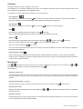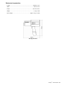
1
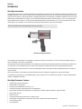
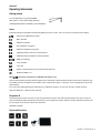
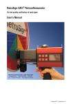
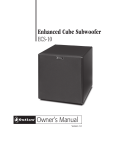
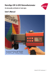
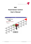
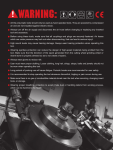
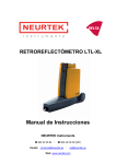
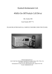
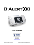
RetroSign® Retroreflectometer
On site quality verification of road signs
User’s Manual
DELTA Danish Electronics, Light & Acoustics
Venlighedsvej 4 · 2970 Hørsholm · Denmark
Tel. (+45) 72 19 40 00 · Fax (+45) 72 19 40 01
www.roadsensors.com
®
RetroSign · Retroreflectometer 1
DISCLAIMER
The information contained in this document is subject to change without notice.
DELTA MAKES NO WARRANTY OF ANY KIND WITH REGARD TO THIS MATERIAL, INCLUDING, BUT NOT LIMITED TO,
THE IMPLIED WARRANTIES OF MERCHANTIABILITY AND FITNESS FOR A PARTICULAR PURPOSE. DELTA SHALL NOT
BE LIABLE FOR ERRORS CONTAINED HEREIN OR FOR INCIDENTAL OR CONSEQUENTIAL DAMAGES IN CONNECTION WITH THE FURNISHING, PERFORMANCE OR USE OF THIS MATERIAL.
Rev.: 13-07-2005
2 RetroSign® · Retroreflectometer
Index
Section 1 ............................................................................................................... 5
Introduction .......................................................................................................... 5
RetroSign introduction ....................................................................................... 5
RetroSign Retrometer Features......................................................................... 5
Options .............................................................................................................. 6
Section 2 ............................................................................................................... 7
Operating Information.......................................................................................... 7
Getting started ................................................................................................... 7
Icons .................................................................................................................. 7
Sequence id....................................................................................................... 7
Keyboard functions ............................................................................................ 7
Calibration.......................................................................................................... 9
Menu System..................................................................................................... 9
Battery/ Charging............................................................................................. 10
Remote control ................................................................................................ 10
Support flange ................................................................................................. 11
Aperture Reduction.......................................................................................... 11
Section 3 ............................................................................................................. 12
General Information ........................................................................................... 12
RetroSign® ...................................................................................................... 12
Factory calibrations.......................................................................................... 12
Type 4000........................................................................................................ 13
Type 4500........................................................................................................ 13
Battery ............................................................................................................. 14
Note on error sources ...................................................................................... 14
Section 4 ............................................................................................................. 15
Maintenance ....................................................................................................... 15
General care .................................................................................................... 15
Front Lens........................................................................................................ 15
Battery ............................................................................................................. 15
Lamp................................................................................................................ 15
Reference cap ................................................................................................. 16
Calibration........................................................................................................ 16
APPENDIX A ....................................................................................................... 17
Communication Facilities.................................................................................. 17
RS-232C specification ..................................................................................... 17
Data protocol ................................................................................................... 17
Command format ............................................................................................. 17
Example........................................................................................................... 17
Command set .................................................................................................. 18
APPENDIX B ....................................................................................................... 20
Specifications..................................................................................................... 20
®
RetroSign · Retroreflectometer 3
General characteristics .................................................................................... 20
Environmental characteristics .......................................................................... 20
Mechanical characteristics............................................................................... 21
APPENDIX C ....................................................................................................... 22
Quick Guide For Retrosign Extension Kit........................................................ 22
Connection....................................................................................................... 22
Getting started ................................................................................................. 22
Battery ............................................................................................................. 22
APPENDIX D ....................................................................................................... 23
GPS ..................................................................................................................... 23
DGPS Implementation ..................................................................................... 23
Controlling the GPS function from the menu system ....................................... 23
Controlling the GPS function from the computer interface ............................... 24
Log Data .......................................................................................................... 24
4 RetroSign® · Retroreflectometer
Section 1
Introduction
RetroSign introduction
The RetroSign retrometer is a portable field instrument, intended for measuring the retroreflection properties of road signs in car
headlight illumination. The value R’ (coefficient of retroreflected luminance) is used. R’ is a measure of the lightness of the road
signs as seen by drivers of motorized vehicles in headlight illumination. The RetroSign is available in different versions. For type
4000 the sign is illuminated at an angle of +5º and the angle between illumination and observation is 0.33º. For type 4500 the
sign is illuminated at an angle of -4º and the angle between illumination and observation is 0.2º. This corresponds to an observation distance of 100 meters. Thus, relevant for a motorist viewing situation under normal conditions.
R’ is an important factor in the site quality control of road signs.
DELTA RetroSign Retrometer
The operation of the retrometer is very simple and requires a minimum of instruction. An error or warning message is given in
case of unreliable or erroneous measurement.
The RetroSign measures the retroreflection and calculates R’ according to international agreements. Results are presented on
an LCD panel. The nonvolatile memory provides on site registration of measurements with corresponding date and time.
The RetroSign has a built in function to mark each measurement with a user defined name (measurement id) and a unique sequence number.
Data communication on the RS232 port gives extended command, calibration, diagnostics an data dump facilities.
The RetroSign is powered by a rechargeable battery, giving several hours of measurement capacity. A mains powered battery
charger is supplied as standard.
RetroSign Retrometer Features
•
Portable self-contained instrument
•
Measurement in full daylight
•
Photopic corrected detector and source »A«
•
Automatic stray light compensation and error diagnostics
•
Measurement geometry and illumination corresponding to realistic viewing condition in night time traffic
•
Direct digital read out
•
Real time clock
•
Automatic data storage in internal non-volatile memory
•
S2332 serial communication for operation, data dump, extended control and diagnostics
•
Communication cable
•
Long battery life
®
RetroSign · Retroreflectometer 5
•
230 V/ 50 Hz or 120V/60 Hz mains powered battery charger
•
Automatic programmable power off function
•
Easy calibration procedure
•
Reference cap for calibration
•
Small support flange with cross hair
•
Aperture reducer Ø15 mm (0.60 in)
•
Carrying case
Options
•
GPS
•
Extension pole kit with remote trigger, display and large support flange.
•
Fast 12V powered battery charger (approx. 15 minutes)
•
Battery (extra)
•
Aperture Reducer Ø10 mm (0.40 in)
6 RetroSign® · Retroreflectometer
Section 2
Operating Information
Getting started
Turn the RetroSign on by pressing ON/C.
After approx. 2 seconds the display will show:
Calibrate instrument if necessary, see calibration.
Icons
Instrument status and operational mode are signalled by the use of icons. Icons are shown in the top line of the display.
Instrument is calibrated and ready.
Menu selected.
Calibration selected
Zero calibration in progress.
Reference calibration in progress.
Calibration Monitor Active for normal aperture
Calibration Monitor Disable for reduced aperture
Battery low warning
Log is enabled
Log is full
Sensor is receiving data on the serial communication port
Display backlight is on.
When
is active the instrument is calibrated and ready for use.
Start a measurement by pressing the red trigger knob on the handle. A beep indicates the start of the active measuring cycle.
The display shows an hourglass for the duration of the measurement, approx. 3 seconds. A new beep signals the end of the
measurement.
If any errors are detected during the measurement or calibration sequence, an error icon and error number is shown.
See also Section 3 - Note on error sources.
Sequence id
The RetroSign has a built in function to mark each measurement with a user defined name (sequence id) and a unique sequence number automatic generated by the instrument. The sequence id and the sequence number will also be stored in the
log. The length of the sequence id text is 6 characters.
See Menu system.
Keyboard functions
®
RetroSign · Retroreflectometer 7
ON/Clear
Push shortly to switch on instrument
When switched on it clears the current operations.
Redisplays the last measuring result.
OFF
Turn of RetroSign.
Activate menu system
Scroll key when in menu system
Parameter and value increment/decrement
Calibration
Enter
Trig
Activate menu for instrument calibration
Activate selected function or accept changed settings
Start R’ measurement.
Start fast calibration.
8 RetroSign® · Retroreflectometer
Calibration
RetroSign features two levels of calibration: fast and full.
Fast calibration is an “everyday” calibration using factory zero calibration and default reference value. Default reference value
can be changed only when using the full calibration mode.
Full calibration is used for high accuracy calibration of zero and reference.
Fast calibration
Fast calibration is initiated by pressing the
button and then the trigger. Mount the reference cap (reflective side) before
triggering. Calibration is executed immediately. Default instrument zero (factory setting) used.
Full calibration
Full calibration is initiated by pressing the
button and then
. Follow the procedure displayed.
Zero
Mount the zero cap (dark side) on the instrument. Press
when ready.
When hourglass disappears instrument is ready for next step in the calibration procedure.
Reference
Mount the reference cap (reflective side). Edit reference value using
When the hourglass disappears confirm with
After a successful calibration the
or
until correct. Press
when ready.
when ready. Cancel with the ON/C button.
icon is active.
If for some reason the calibration fails, values from the previous successful calibration are used. This information is displayed
immediately after calibration.
Reduced aperture option
When the instrument is configured for measurements with reduced aperture the calibration monitor should be disabled to
avoid the “Error in Calibration” condition, the display reflects the status for this option. See also paragraph Aperture Reduction
in this section for further information.
Menu System
Press
or
to activate the menu system from top or bottom end respectively. When the menu is selected use
.
scroll through the functions. To select the displayed function press
and
to
Menu points are:
Remove top data in log
This function allows the user to delete the last measurement in the data log. The deletion restores the Sequence ID text string
and measurement counter from the log. The deletion process can be continued until the log is empty. Deleted data cannot be
recalled.
Data log enable /disable. (Log Open).
Clears built in data log. Also shows the remaining space in the log as a percentage. Press
to clear data log.
Off time (power save)
Setting for automatic instrument power off. When selected use
automatic power off!
and
to edit off time. Off time less than 60 sec. will disable
Initialize instrument
Initialize the instrument to factory default settings. The instrument has to be calibrated afterwards. The log data and sequence
id are not affected but the log is closed afterwards.
®
RetroSign · Retroreflectometer 9
Display light
to toggle operation. When the display light is enabled the
Enables or disables the display back light. Press
displayed. The back light will illuminate for a moment when any key or the measurement trigger is pushed.
icon is
Clear Seq_ID
Clears the sequence id as if all 6 positions were set to spaces. Press
to clear. See also Sequence ID.
Sequence ID (Old Seq_ID)
If any sequence id is defined, the id text and a sequence number is shown in the display. To edit the sequence id press the
button. The cursor is placed to the right of the first character position. Use the button to scroll through the alphabet in
direction 0..9, A..Z starting with the space character. The button will scroll through the alphabet in opposite direction. When
button to advance to the next position. You have to step through all 6 positions
the wanted character is shown press the
before the sequence id function can be accepted.
When typing a new sequence id text or editing an old one, the sequence number is reset to 0. When all 6 positions are set to
space the sequence id function is undefined and no longer included in the log nor shown in the display.
Mean Value Calculation
The Mean value is calculated and displayed together with the number of measurements used for the calculation when two or
more measurements are made in succession.
The Mean calculation is cleared whenever the instrument is turned OFF, Calibrated or the ON/C Key is activated. The Mean
value will not be logged!
Battery/ Charging
Temperatures in excess of 50º C (122º F) will damage the battery. Do not short circuit the battery. Do not dispose with household waste.
To remove the battery swing the battery retaining spring over, and pull out the battery from the handle. See Section 4 - Battery
for further information on charging.
Remote control
External trigger
By use of the connector on the rear of the instrument, it is possible to remotely trig the instrument. As an accessory an Extension pole kit can be supplied.
Serial communication
The instrument is equipped with a serial communication port. This allows complete instrument control and data collection.
Use the RSC software to control the RetroSign.
Serial communication setup (R232 interface):
9600 baud, No parity, 8 bit, 1 stop bit
Selected commands.
LO
(Log Open):
Enables log for input.
LD
(Log Dump):
Number, date time, R’, mode.
RM
(R’ Measurement):
Start R’ measurement.
SD
(Status Dump):
Returns instrument settings and status.
On line help
?
The RetroSign will return a brief help page of
commands.
See also Appendix A - Communication facilities.
10 RetroSign® · Retroreflectometer
Support flange
The support flange is provided with cross hair markings. It makes it easier to decide the measuring position when taking measurements on small objects, e.g. letters and numbers on a sign.
Aperture Reduction
For special measurement requirements on small targets, the RetroSign can be mounted with a special aperture reducer adaptor, this reduces the field of measurement to either ø 15 mm (0.6 in) or ø 10 mm (0.4 in) depending on the unit used. The ø 10
mm is supplied with the RetroSign.
To achieve the smaller aperture, the reduction unit is simply mounted in front of the lens barrel.
Disable the Calibration Monitor when using the Reducer!
Disabling the calibration Monitor:
Press the
or
until the display shows:
Calibration Monitor ON
Disable Now
Press
to Disable.
Enabling the Calibration Monitor:
Press the
or
until the display shows:
Calibration Monitor OFF
Enable Now
Press
to Enable.
Sequence ID
From firmware version 1.28 the valid range for the Sequence ID has been reduced to only allow for the space character,
numbers and the capital letters A to Z.
Note:
•
RetroSign is an optical precision instrument, handle with care.
•
Store in clean an dry environment.
•
Do not recharge after using only briefly.
•
Check or change reference cap frequently.
®
RetroSign · Retroreflectometer 11
Section 3
General Information
RetroSign®
The RetroSign retrometer measures the R’ (coefficient of retroreflected luminance) parameter. The R’ parameter represents the
retroreflection of the road signs seen by drivers of motor vehicles by headlight illumination.
Physically the retrometer is a small hand held instrument. It is constructed in an aluminium housing, containing electronics and
the optical system. The measurement trigger button and the replaceable battery are housed in the handle.
The RetroSign is controlled by a micro controller. The micro controller executes a measurement automatically when the trigger
is activated and the result is shown on the display. The result is automatically transferred to the internal nonvolatile memory if
logging is enabled. The RetroSign is operated from a small keyboard on the left hand side of the retrometer. The retrometer
control is also possible by a serial communication link (RS 232). Stored data can be transferred to a PC for further processing.
Factory calibrations
The retroSign retrometer is factory calibrated. This calibration is carried out by using a special reference. The reference’s R’
value is measured in the laboratory using traceable methods and equipment.
The enclosed reference cap can be used for verification or recalibration of the retrometer.
12 RetroSign® · Retroreflectometer
Type 4000
In the RetroSign the illumination angle is +5° and the offset between observation and illumination angle is 0.33°. The measurement area is approx. ø 30 mm.
Type 4500
In the RetroSign the illumination angle is -4° and the offset between observation and illumination angle is 0.2°. The measurement area is approx. ø 30 mm. Or ø15 mm/ø10 mm when using the reduced aperture adaptor.
According to ASTM R’ named RA.
®
RetroSign · Retroreflectometer 13
Battery
The RetroSign is powered by a replaceable rechargeable battery, which under normal operation will keep the retrometer operating in several hours. The battery must be recharged by the incluced external charger. See also Section 4 - Battery.
Note on error sources
The RetroSign is factory calibrated. Nevertheless, begin important measurements sessions with a calibration. See also Section
4 - Maintenance.
The RetroSign can take measurements without being in close contact with the sign surface. But to obtain the most reliable results the front of RetroSign should be in contact with the surface of the sign when taking measurements.
During each measurement the RetroSign automatically evaluates the optical leakage and the result are compensated before
read out. Leakage will under normal conditions not be significant. Nevertheless, it may occur and a warning will be shown in the
display. Leakage is primarily caused by stray light entering the optics between the sign and the instrument.
Instrument leak, drift and offset errors are compensated for by means of data obtained during the calibration procedure, so perform the calibration procedure carefully. It is very important to keep the front lens and the surface on reference cap clean.
The optical property of a sign alters when the retro reflective material becomes wet. The RetroSign can take measurements on
wet or misted up sign surfaces but readings are not comparable with readings taken on dry signs.
Because of the special optical properties of micro prismatic sheeting, some precautions should be taken to get correct readings.
Always use the RetroSign in the angle specified for the sign.
Typically RetroSign must be held in a vertical position.
The RetroSign retrometer is a rugged instrument, but it is an optical instrument and must be handled as such.
Store instrument in a clean and dry environment.
14 RetroSign® · Retroreflectometer
Section 4
Maintenance
General care
The retrometer is constructed for outdoor use in ordinary good weather conditions. It will withstand moist weather, but caution
must be taken against rain or splashes and dirt form traffic. The RetroSign retrometer is an optical instrument and shall be handled as such. Avoid exposing the instrument to shocks and vibrations.
Front Lens
The lens does not need special maintenance. If dirty carefully moist the lens with ordinary window cleaning liquid and clean it
with a soft cloth.
Battery
The instrument is powered by a Ni-Cd battery, which under normal use requires no maintenance.
A battery charger is provided as a standard accessory for charging the battery from mains.
To recharge the battery, swing over the battery retaining spring and remove the battery from the handle.
Please refer to the enclosed charger instructions for operation.
A new battery or one which has not been used for an extended period will reach full performance only after approx. 5 charging
and discharging cycles.
The battery is equipped with a temperature monitor which allows charging only within a range between 0°C and 45°C (32°F and
113°F). This ensures long battery life. When used properly, the battery can be recharged up to 1000 times.
A substantial drop in operation period per charge indicates that the battery is worn out and must be renewed.
The Battery and the charger are specifically designed for use in conjunction with one another. Charging should be done only
with the charger delivered with the instrument.
Do not expose the battery to heat or flames: Danger of explosion. Do not place the battery on a heater or expose to direct
sunlight for long periods. Temperatures in excess of 50°C (122°F) will damage the battery. Allow a warm battery to cool before
charging. When the battery is outside the instrument, cover the contacts to avoid short circuits.
Avoid repeated consecutive rapid charges of the battery. Do not recharge after using only briefly.
Note
•
The battery should be protected against impact. Do not open the battery.
•
Store the battery in a dry place.
•
Due to environmental protection do not dispose the battery with household waste.
Lamp
The lamp requires no maintenance. At the end of the lamps service life the instrument will display a lamp error message, and
the lamp must be replaced.
The lamp must be replaced only by personal trained by DELTA.
®
RetroSign · Retroreflectometer 15
Reference cap
To make sure that the calibration of the retrometer is correct it is important that the surface on the reference cap is clean and
undamaged. Keep the cap protected, and be careful not to touch the reference cap (reflective side).
If the surface is stained, scratched, or broken the reference cap must be replaced.
In case of dust on the surface, clean it gently by using a soft cloth with a mild household detergent. Wipe carefully with dry cloth
afterwards.
To ensure reliable measurements, it is recommended that the reference cap is periodically recalibrated to a traceable standard.
DELTA Light & Optics offers calibration traceable to PTB (Physikalisch-Technishe Bundesanstalt). For information contact your
local distributor or DELTA Light & Optics, Denmark.
Reference CAP
Calibration
The RetroSign is factory calibrated, but a calibration should always be carried out before starting a series of measurements.
After compensation of zero signal, leakage and other known “errors” the calibration factor is easily calculated. This is done
automatically by the instrument if the calibration routine is followed. After a calibration the retrometer will display »true« R’.
Store the reference cap in a dry and clean environment.
See also Section 2 - Getting started and Section 3 - General information.
16 RetroSign® · Retroreflectometer
APPENDIX A
Communication Facilities
RS-232C specification
The RetroSign is equipped with a communication facility that enables the use of a regular PC type computer for control of the
RetroSign functions and for data dump from the internal data log.
The PC connects to the RetroSign using the connector on the rear and a special communication cable. The cable is mounted
with a 9 pin female connector for computer connection. Use of a 9 to 25 pin adaptor may be necessary on some computers.
The electrical connections meet the normal standard for serial communication.
Data protocol
The communication between the RetroSign and the computer equipment takes place using the following settings:
Baudrate ................................ 9600 bit/sec.
Number of data bit .................................... 8
Parity .................................................. none
Stop bit ..................................................... 1
Command format
All RetroSign commands are built using the following template.
Command
Letters (not case sensitive) or <?>.
Delimiter
One or more spaces, optional.
Parameter
One or more interger or real numbers separated by space,
optional. Parameters in square brackets are optional. If no
parameters are entered the actual value is returned.
Delimiter
One or more spaces, optional.
Command end
Carriage Return (<CR>), mandatory.
The RetroSign can respond to a command in two ways: data mode or text mode. The RetroSign always powers up in the data
mode. This mode is used by the RSC- Road Sensor Control program.
A special command, TXT, is used to set The RetroSign to respond in text mode.
The user should set the RetroSign to respond in text mode if a simple communication program is used instead of the RSC program.
Example
The user wants to set the automatic off timer to 120 seconds.
The command should look like this:
OT 120 <CR> or OT120<CR>
If the RetroSign accepts the command it responds:
120
In text mode it responds with the message:
Automatic Off Timer = 120 sec.
If for some reason the communication fails or the command is rejected the RetroSign responds with a question mark <?>.
If the parameter exceeds the defined range for that parameter, the RetroSign returns the present setting without any change.
®
RetroSign · Retroreflectometer 17
Command set
The following is a complete list of Commands and Actions.
Command:
Action:
BL [T/F]
Display Backlight True/False
True enables display light. False disables light.
DA [yyy mm dd]
Set year, month, date in real time watch.
DA without parameter returns current date and time from watch.
FV
Returns Firmware Version.
II
Initialise Instrument settings. Confirm with <Y>.
ID
Query RetroSign instrument s/n
Return the instrument serial number.
LA
Lamp current Alarm.
Returns set point for low lamp current alarm.
LC
Lamp Current.
Returns the lamp current measurement from the last RM.
LD[n1 n2]
Log Dump.
Returns measuring number, date, time R’, mode and sequence id. Each value are separated by comma. Data can easily be imported in a spread-sheet e.g. Microsoft Excel.
LD without parameters will respond like this:
1 ,2001-07-30 08:22:53 ,200 ,0 ,Roadxy,1
2 ,2001-07-30 08:23:42 ,385 ,0 ,Roadxy,2
3 ,2001-07-30 08:26:58 ,210 ,2
4 ,2001-07-30 08:27:58 ,296 ,0 ,Roadxy,3
End of Log File
Column 1 = measurement number, 2 = date/time of measurement, 3= measured value, 4 =
mode, 5= sequence id (if any).
Mode indicates what kind of measurement was executed:
0= normal measurement, 1 = fast calibration,
2 = full calibration, 3 = calibration via communication port (RC-command).
Including parameters to the LD command specify the log start number and the length
(number of lines). If n2 are omitted data starts from log position n1 and to the end of the log
file.
LD 50 5 will respond like this:
50 ,2001-07-25 11:15:00 , 210 ,0 , xyz-a, 34
51 ,2001-07-25 11:17:00 , 180 ,0 , xyz-a, 35
52 ,2001-07-25 11:20:00 , 302 ,0 , xyz-a, 36
53 ,2001-07-25 12:00:00 , 210 ,3
54 ,2001-07-25 13:15:00 , 235 ,3 , xyz-a, 37
End of Log File
A log dump can be terminated by any key.
LO
Log Open.
Activates the built-in log for storing measuring and calibration data. Measuring number,
18 RetroSign® · Retroreflectometer
date, time R’, mode and sequence id are logged. Only valid measurements and calibrations are logged.
LR
Log Reset.
Deletes all stored data. The Log must be open. Confirm with <Y>.
LS
Log Stop.
Closes the log. Measuring data is no longer logged.
OT [n]
Auto Off Timer n=seconds (0..599 sec.).
Set the time for automatic instrument turn off.
n < 60 disables the automatic off timer.
RC [n]
RetroSign Calibration. Use RC on the reference standard. n=calibration value from the
reference standard. RC without parameter returns the calibration value (n).
RM
R’ Measurement.
Executes measurement cycle. Return R’. Same as using instrument trigger.
RR
Read R’
Returns result of last RM-command.
RZ
RetroSign Zero calibration. RZ is a part of the instrument calibration procedure. Use RZ on
the reference cap’s zero standard. Confirm with <Y>.
Must be succeeded by the RC-command.
SD
Status Dump.
Return instrument status. All settings and values are displayed. Used for verification and
trouble shooting.
SN [nnnnnn]
Sequence if text. Maximum 6 characters including spaces.
6 spaces disables the sequence id text.
TI [hh mm ss]
Set TIme in real time.
TI without parameter returns current date and time from real time.
TO
Turn RetroSign Off immediately. Same as pressing the OFF button on the keyboard.
TX [T/F]
Text mode True/False.
If TX is true RetroSign will return information to the serial port in plain English. An instrument power on TX will always be false.
VA
Voltage Alarm.
Returns set point for low battery warning icon.
VB
Voltage Battery.
Returns actual battery voltage.
VS
Voltage Status.
Returns battery voltage with and without lamp switched on. Returned values are from last
time the lamp was switched on.
?
Returns help menu.
®
RetroSign · Retroreflectometer 19
APPENDIX B
Specifications
General characteristics
Type 4000
Geometry .......................................................................... Din 67520: 5°/0.33°
Illumination angle....................................................................................... + 5°
Illumination /observation angle .................................................................0.33°
Light source angular aperture ...................................................................0.16°
Receptor angular aperture ........................................................................0.16°
Type 4500
Geometry ......................................................................ASTM-E-1709: -4°/0.2°
Illumination angle..........................................................................................-4°
Illumination/observation angle ....................................................................0.2°
Light source angular aperture .....................................................................0.1°
Receptor angular aperture ..........................................................................0.1°
Type 4000/4500
Field of measurement ................................................................. ø 30mm/1.2in
Light source ................................................................................Illuminant »A«
Receptor sensitivity.........................................................Precise eye corrected
ASTM-E1709para. 6.4.2 for selected color filters)
Min. reading (cd/lx×m²) ................................................................................... 0
Max reading (cd/lx×m²) .................................................................... Typ.2000
Electrical characteristics
EMC ............................................................................................. EN 50081-1
EN 50082-1
Power supply:
Battery ............................................................ Replaceable NiCd 9.6 V/1.2Ah
Bosch part number: 2 607 335 012
External charger ....................................................... Mains voltage 230 V AC
Optional: 120V / 60 Hz
Charge time ..................................................................... Approx. 15 minutes
Data memory ....................................................................1000 measurements
Data retention (from purchase) ..................................................... Typ. 5 years
Interface................................................................................................ RS 232
Serial communication mode............................................................9600, N,8,1
Environmental characteristics
Operation temperature:....................................................................0°to +45°C
32°F to 113°F
Storage temperature: ................................................................ -15°C to +50°C
5°F to 1229°F
Humidity ................................................................................. Non condensing
20 RetroSign® · Retroreflectometer
Mechanical characteristics
Length.......................................................................................295mm/ 11.6 in
Width...........................................................................................83 mm / 3.3 in
Height ......................................................................................324 mm/ 12.8 in
Weight........................................................................................ 2,1 kg / 4.6 lbs
Gross weight..................................................................Approx. 6 kg / 13.2 lbs
RetroSign dimensions.
®
RetroSign · Retroreflectometer 21
APPENDIX C
Quick Guide For Retrosign Extension Kit
Connection
The battery in the display module is mounted by unscrewing the bottom plate and removing the battery container. Insert the new
battery, notice that the red wire of the battery container must be connected to + terminal. Assemble the Extension kit in reverse
order.
Mount the Extension kit on the Extension pole by using the two screws and the black profile that is included in the package.
Connect the Extension kit to the RetroSign.
Getting started
Turn off the RetroSign.
Take a measurement by pressing the <R’> button on the Extension kit.
The display shows (the measurement is an example):
--230
The result of the measurement is the same as shown on the RetroSign and the instrument is now ready for a new measurement, just press the <R’> button ones again.
If no measurements are made, the Extension kit will keep the RetroSign on for appr. 4 minutes, whereafter the Extension kit
automatically will shut down. The RetroSign will shut down according to the time-out for the instrument.
If an error occurs during a measurement the Extension kit show:
Err
Possible errors see the RetroSign manual.
If the <R’> button is pressed while the RetroSign is turned off, the display will show “Err” the moment the RetroSign is turned on.
This is not an error, just push the <R’> once again and the measurement is made.
Battery
The battery should be changed at least once a year.
If the Extension kit is not used it will still use a small amount of power, so do not mount the battery before use.
When the battery voltage is low, the display will show »LO BAT«
The battery type is: DL123A, 3V, 1.300 mAh. (or similar).
22 RetroSign® · Retroreflectometer
APPENDIX D
GPS
DGPS Implementation
The GPS function is activated when the GPS unit is attached and the GPS Option has been enabled. Due to the fact that the
GPS receiver first has to receive signals from several satellites before it can calculate its position, it will take a short time before
a “Good Fix” can be achieved, typical this process will take from a few seconds up to 35 seconds depending on how long the
device has been out of use and also on how far it has been moved away from the last fix position.
When a position has been calculated, the GPS Icon appears in the top Icon row and the position and status will be updated, the
position and status data will only be displayed if GPS is set to ON in the menu.
The display will show ___No_Fix___ until the first valid position has been calculated, then the following GPS information will be
shown.
Line 1)
Latitude in the format ddmm.mmmm and the Latitude Hemisphere N
or S.
Line 2)
Longitude in the format dddmm.mmmm and the Longitude Hemisphere W or E.
Line 3)
The Horizontal Dilution Of Precision HDOP value in the range from 0.10 to 99.99, the lower the value the more accurate the position Fix. The number of received satellites is also shown.
Line 4)
The DGPS mode received by the GPS unit, it can be:
■
■
■
■
GPS when no correction data is received.
WAAS when correction data from the WAAS satellites are used
EGNOS when correction data from the EGNOS satellites are used
unknown when ambiguous correction data.
Example: Position for DELTA located in Hørsholm, Denmark
Display
5552.4610N
01229.7490E
HDOP: 1.09 11
Mode: WAAS
meaning
55°52.4610’N
12°29.7490’E
HDOP=1.09 and 11 satellites used in calculation
Position correction based on WAAS satellites.
All GPS Position data and status are stored in the internal data log, when enabled, and can de retrieved with the normal Log
Dump command.
A special version of the RSC program is needed to supports the new GPS facility.
Controlling the GPS function from the menu system
Use the
keys to select the GPS menu.
GPS On: The GPS data will be displayed, press the
GPS Off: The GPS data will not be displayed press the
key to turn this function off
key to turn this function on.
Controlling the DGPS function from the menu system:
Use the
keys to select the DGPS menu.
The display can show either
DGPS Mode: WAAS. The DGPS mode is set to to use the WAAS satellites for position corrections.
DGPS Mode: EGNOS. The DGPS mode is set to use the EGNOS satellites for position corrections.
DGPS Mode: Auto. The DGPS mode is set to use the available satellites for position corrections.
DGPS Mode: Off. The DGPS mode is turned off, the correction signals will be received but not used, this can be desirable
in situations where the correction satellites is very low on the horizon, as would be the case at high latitudes, also take note
that using a correction signal from a Satellite designed to correct position data for a different region, can result in degraded
precession, this would be the case when using WAAS in Europe.
®
RetroSign · Retroreflectometer 23
In all cases, the shown DGPS mode can be turned on or off by pressing the
The active DGPS mode can be changed with the
key.
key.
If DGPS mode is Off the
key toggles through the possible choices which then can be activated by pressing the
If DGPS mode is On the
key.
key changes the DGPS mode directly, and the selected mode can be set off by pressing the
Controlling the GPS function from the computer interface
The GPS and DGPS modes can be set using a special Set DGPS Mode command send on the computer interface.
GPS/DGPS commands:
GP
Return GPS/DGPS settings.
GP0
Set GPS display off, disable DGPS reception
GP1
Turn GPS display on, disable DGPS reception
GP2
Set GPS display off, enable DGPS reception
GP3
Turn GPS display on, enable DGPS reception
Prompt code 47:code
DGPS mode selection:
@DG
Return selected DGPS mode.
@DG0 Turn DGPS calculation off.
@DG1 Set DGPS calculation to use WAAS correction satellites.
@DG2 Set DGPS calculation to use EGNOS correction satellites.
@DG3 Set DGPS calculation to AUTO to use available correction satellites.
Prompt code 46:code
Log Data
Extra DGPS information has been added to the LOG
A typically log entry could look like this:
25: 52 2005-01-20 10:48:24 5 0 HX01 28 5552.4610N 01229.7505E 11 0.80 1 0
The last two bold values are the Instrument DGPS mode and the Received DGPS mode
The Instrument DGPS mode can be:
0
1
2
3
Off
WAAS
EGNOS
Auto
The Received DGPS mode can be:
0
1
2
3
WAAS
EGNOS
MSAS
DGPS
24 RetroSign® · Retroreflectometer
key.