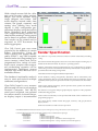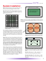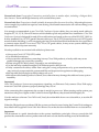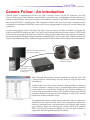
1
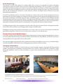
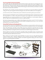
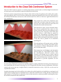
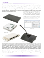
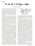
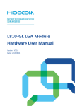
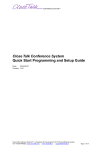
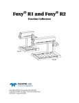
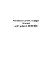
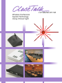
Wireless Conference
System Technology
Using Infrared Light
In the beginning...
The history of Close Talk started in Sweden 1988 with a vision of a completely wireless telephone
conference system for board rooms and other high-end installations. The use of radio was quickly
discarded and infrared light was chosen as carrier. In 1989 the first delivery of this hand-made, highgrade wooden box microphone system was made. During the coming five years over 500 units where
sold on the Scandinavian market to a wide selection of state, municipal and well known local and
international companies.
In 1997 Close Talk decided it was time to introduce it’s idea to the world. The development of a new
generation for the mass-market was started to include products and components designed for ease of
use, quick installation, reliability, long life and a reasonable price. At the turn of the millennium the
first generation of this new product line saw the light of day. The following two years included a hectic
time to build the local Scandinavian market and finally in 2002, generation two was introduced internationally at the annual ProLight&Sound trade show in Frankfurt to intense market interest.
In 2005 generation three was introduced world-wide with a host of new features, laying the foundation for the solid conference technology product range available today.
Building on a long time of product experience, Close Talk Conference System will continue towards the
goal of becoming the worlds most price-worthy wireless conference- and voting system!
Project history and market impact
Close Talk Conference System has been sold in many thousands of units to numerous prestigious customers such as presidential and governmental offices, United Nations, World Bank, US Senate, numerous
municipalities and corporations all over the world.
Key features highly appreciated by the customers are ease of installation, ease of use, excellent design,
excellent reliability, total safety to eavesdropping and excellent value for money.
Company information
Close Talk Conference System is owned and run by the Swedish company Apodosis AB that handles
product development, marketing and production. The system is fully produced in Sweden, using
local subcontractors. Visit us at www.closetalk.se, e-mail us at [email protected] or call us at +46-(0)87645227.
© Copyright 2012 - 2015 Close Talk Conference System /Apodosis AB, Sweden
All rights reserved. All copying, either in whole or in part, by any means, of this document, for any purposes or use other than to promote Close
Talk Conference System, is strictly prohibited! For best results, this document is supposed to be printed dual-sided.
Document version: 5
2
Released 2015-March-22
All specifications subject to change without prior notice.
The Close Talk Conference System
A basic audio-only Close Talk Conference System consists of one or more DU-111-02 Delegate Unit, usually one per conference participant, one CU-110-11 Central Unit which is the system controller, a number of TU-100-xx Transceiver Unit where the required number depends on the required room usage
area of the system, a battery charger solution for the delegate units and finally some cables to connect
the transceiver units to the central unit.
The delegate unit is a battery powered, all-inclusive unit, there are no special models for chairman,
voting, etc. The system supports unlimited delegate units with a limit of three active microphones.
A central unit acts as the controller of the system with built-in automatic speaker queue and more.
Transceivers acts as transmitter/receiver antennas for the IR-signals and are connected to the central
unit using RJ-45 Cat. 6 cables. The central unit supports up to eight direct connected transceivers,
supporting the most common installation sizes. For larger installations or with complex cabling, an
SB-110-01 Split Box is available that acts as a one-to-six port expander.
Two battery charger solutions are available for the delegate units, the low-cost DC-110-45 Cord Battery
Charger and the CT-10 Trolley Charger that besides battery charging also provides a very convenient
transportation and storage functionality.
Close Talk Conference System deluxe
Close Talk Conference System is a completely modular conference system, the basic audio-only system
described above can at any time and at the users convenience be expanded in room size, more delegate
units, teleconferencing, recording, camera follow, big screen projection of speaker lists and voting
results, voting, speaker and reply list control, attendance management and more, there are no future
technology dead-ends waiting around the corner because of system design decisions today.
The PC-software Close Talk Control has been, and still is being, developed in close co-operation with
municipalities and councils to provide the world markets most powerful conference system solution
for formal conference and discussion control.
Being wireless, the system provides super flexibility for room re-use. By using infrared light the
system investment has a virtually unlimited in time operational guarantee whereas radio based
systems are experiencing increasing problems with ether congestion, making Close Talk Conference
System a very good long-time investment.
Basic components for a conference system:
Delegate Unit DU-111-02
Transceiver TU-10002, -03 or -04
or
Central Unit CU-110-11
Charger DC-110-45
Trolley Charger CT-10
3
Catalogue Contents
r System Introduction - page 5
Describes the system principles, product selection, installation and usage
r DU-111-02 Delegate Unit - page 7
Updated - DU-111-02 Delegate Unit is the main microphone and voting unit. There is no special chairman unit in Close
Talk Conference System, any unit can be chairman via controller programming
r CU-110-11 Central Unit - page 9
Updated - CU-110-11 Central Unit is the main system controller. The built-in microprocessor controls the entire system
including an RS-232 port for remote control applications
r TU-100-02 Transceiver Unit - page 11
A Transceiver Unit acts as the system antenna. The TU-100-02 Transceiver Unit is for flush mounting using a BOSE ceiling
speaker mounting pattern
r TU-100-03 Transceiver Unit - page 13
TU-100-03 Transceiver Unit is for flush mounting using spring fastener, suitable for false ceilings
r TU-100-04 Transceiver Unit - page 15
TU-100-04 Transceiver Unit is suitable for surface mounting
r SB-110-01/2 Split Box - page 17
Updated - SB-110-01/2 Split Box is used to expand the number of supported system transceivers
r SU-110-01 Switcher Unit - page 19
New - SU-110-01 Switcher Unit provides automatic switching of adjacently installed systems
r Cables - page 21
Installation cables for the Transceiver units
r DC-110-45 Cord Battery Charger - page 23
DC-110-45 Cord Battery Charger is a low-cost battery charger for the DU-111-02 Delegate Unit and supports five units per
charger
r CT-10 Charger Trolley - page 25
CT-10 Charger Trolley is a combined battery charger, transportation and storage trolley for the DU-111-02 Delegate Unit
and supports up to twenty four units per trolley
r CH-103 Tray Battery Charger - page 27
CH-103 Tray Battery Charger is a fully automatic battery charger for the DU-111-02 Delegate Unit and supports three
units per charger. It is normally a part of the CT-10 Charger Trolley but can just as easily be mounted on a wall, in
cupboard or a third party trolley
r CTPS-101 Battery Charger Power Supply - page 29
CTPS-101 Battery Charger Power Supply is a high-powered power supply for the CT-10 Charger Trolley/CH-103 Tray
Battery Charger charger products
r Close Talk Control PC software - page 31
Close Talk Control is a Windows compatible PC software that greatly expands Close Talk Conference Systems functionality
including voting, camera follow and much more
r System Installation Application Note - page 33
Updated - This application note is an instruction for installing the system
r Camera Follow Application Note - page 35
Camera follow functionality is implemented via the PC software Close Talk Control as described in this application note
r 1 + 1 Language Application Note - page 37
Although expands Close Talk Conference System is primarily a single language system it is possible to do 1 + 1 as
described in this application note
4
Introduction to the Close Talk Conference System
The Close Talk Conference System is a wireless discussion system based on infrared light transmission
which ensures easy installation, superior reliability and security.
The basic system components are the Delegate Unit which is the microphone unit used by the conference participants, the Central Unit that controls the system functionality, the Transceiver Unit which is
the infrared transmitter and receiver unit and the Split Box which is used as a signal distributor for
easy installation.
The system has a total of six channels, four
audio and two data where the Central Unit
receives up to three audio and one data and
transmits one audio and one data.
Fig. 1: Transceiver Units positioned in the ceiling
The transceiver units acts as infrared antennas and are positioned face down on the
ceiling. Directly below are the delegate units
that receives the outgoing audio and data
channel. When a user wants to speak he
presses the microphone activation button
and if there is a free audio channel, the microphone will be activated in less than a second,
if not, the unit is placed in an automatic
speaking list.
The microphone will remain active until the
user releases it by pressing the button again.
A maximum of three microphones can be
active at the same time.
The transceiver- and delegate unit transmits
infrared light in a cone-shaped form where
the transmission effective surface area
increases with height up to a limit at about
seven metres (see unit data sheets for actual
data). Several transceiver units are used in a
grid pattern to provide operation for the
required area.
Fig. 2: Delegate Units transmits in the opposite direction
Several types of transceiver units are available, both for surface and flush mounting. The transceivers
are connected to the Central Unit using Cat. 6, S-STP grade RJ-45 cables for easy installation. While the
central unit can accept up to eight directly connected transceiver units, a Split Box can be used to
expand that number.
Another important use for the split box is to reduce the cable lengths in an installation, running a lot of
cables from a ceiling down to a technical room, where the central unit is usually placed, is impractical
and expensive. The split box is placed as close to the transceiver units as possible, reducing the number of cables needed for the central unit.
5
The central unit is a microprocessor based control unit for the system. It provides the basic conference
system functionality such as audio channel management, speaker list and chairman override without
operator assistance. In addition it has an extensive set of audio in- and out connections, microphone
insert, HF infrastructure connectors and RS-232 serial port. A clean and easy-to-use front panel makes
it very simple to access the settings. The unit functionality can easily be upgraded on the field via
firmware upgrade. The unit also has an extensive control command set via RS-232 for system testing
and remote controlling applications.
Close Talk Control is a powerful PC software
that via the RS-232 port expands the
system dramatically to provide the tools
for professional conferencing including
voting, speaker lists, advanced database
technology and camera follow, all packaged in an easily learned user interface.
Central Unit
Close Talk Control
Transceiver Unit
Split Box
Delegate Unit
The delegate unit has an elegant case design suitable for all environments and is very easy to use, only
two buttons to operate. Battery operated with built-in speaker, several microphone alternatives and
headphones output. Battery operating time is typically over twenty hours of listen-only, over eight
hours of speaking. No special charging arrangements, continuous charging supported without
degrading the battery. Battery is of industry standard type and can easily be replaced in the field.
Setting up a system is very easy for the end-customer, simply turn the central unit on, place the delegate units in the room, turn them on and start using the system. Chairman priority functionality
includes speaking channel guarantee and control in several manners to fit all meeting cultures. Close
Talk Conference System is equally suitable as a ten delegate teleconferencing system as a full 100+ large
conference room installation.
6
Delegate Unit DU-111-02
The DU-111-02 Delegate Unit is a wireless microphone and voting station with built-in speaker and
headphones functionality.
Updated - Beginning December 2014 an updated
version is shipping with enhanced audio quality.
Variable length
microphone
Power & Speak
Buttons
IR Transmitter &
Receiver
The unit uses infrared light as transmission media
and has full duplex audio capability.
73
The microphone features include high audio quality, low noise and variable length.
Supports four transmitted channels, three audio
and one data, and two received channels, one audio
and one data.
205
125
Millimeter
Powered by an industry standard lead-acid battery
ensures fully wireless operation, exceptionally long
operating time and superior reliability.
Easy battery handling supports continuous charging.
Simple operation, only two buttons. No setup
required, all settings are controlled remotely.
Simply place the unit within range, turn power on
and start using.
Single audio volume knob with individual operation for speaker- and headphone levels.
Universal design, no special chairman unit or
voting station versions.
Excellent audio characteristics using high quality
driver and base reflex box tuning design.
Unit firmware can be easily be updated via infrared
data link.
The use of infrared light ensures full security from
eavesdropping.
Industry unique variable length microphone suits
all users.
7
Technical Data
Tender Specification
Audio:
The Delegate Unit is to comply with all relevant CE
regulations.
- 200Hz - 7500Hz (-3dB) frequency range
- S/N ratio > 80dB
- Individual level settings for speaker and headphones
- Built-in high quality, polypropylene cone, 2.5” speaker
- 3.5mm stereo mini-tele connector for headphones,
minimum impedance 8 ohms
- Automatic speaker shut-off when inserting headphone
Power:
-Built-in 6 volt, 3.2Ah lead-acid battery
- Industry standard battery type
- Battery easily replaced, does not require return to factory
- Operating time (fully charged) 20 hours listen-only,
8 hours effective speaking time
- Estimated battery life greater than 5 years in normal use
- Charging time (fully discharged) 10-14 hours
- Fully automatic charging
- Continuous charging without battery degradation
Transmission:
- Fully wireless operation using infrared light
- Vertical transmission
- 6 channels, four transmitted and two received
- Frequency range 2.4 - 5.6MHz
- IR wavelength 875nm
- Insensitive to visual light including fluorescent
- Analog FM modulation
- Audio channel S/N ratio 60dB, companded to
greater than 80dB
- Data channel bit phase modulated, 1.67kb/s
Physical:
- Size 205x125x73mm (wxdxh)
- Weight approx. 1.2kg
- Grey plastic case
- Microphone length 270-480mm
Environment:
- Indoor home or office use only
- Temperature +10-35 deg. celsius
- Battery contains lead, recycle according to local
laws and regulations
- Recycle case and contents according to local laws
and regulations
- Clean using soap-water damped cloth only
Approvals:
- CE and FCC approval
- Unit emits safe and harmless infrared light
Order code: DU-111-02
8
The unit is to be designed for independent use by a single
person and shall be able to transmit and receive audio in full
duplex.
It shall have a built-in speaker and a 3.5mm stereo mini tele
connector for optional headphones use. The volume levels
should be independently presettable for speaker- and
headphones and the speaker audio should be automatically
shut off when a headphone is used.
The unit should be fully wireless using harmless, eavesdrop
safe, infrared light as transmission media. Infra-red light is
to be transmitted vertically relative to operators position.
Audio and data is to be transmitted using analog Frequency
Modulation and use carrier frequencies in the range 2 to
6MHz and use infrared light with 875nm wavelength.
The unit power source shall be a rechargeable, maintenance
free battery of industry standard type and be able to be
replaced by the end user. The operating time of a fully
charged battery shall be minimum 20 hours of listen only
and 8 hours of effective speaking time. The re-charging time
of a fully discharged battery shall be no longer than 14
hours. A low battery indication shall be included using an
LED lamp indicator. The unit should power down automatically 2 minutes after the loss of the main audio carrier.
Unit type shall be of universal use including built-in voting
and chairman functionality. Unit functionality should be
easily upgradeable via wireless firmware updates.
Operation of the unit shall consist of a clearly organised, two
button operator panel with 4 LED lamps showing power
status, microphone activity and voting result selection. A
volume knob should be easily accessible for speaker and
headphones level setting. The microphone shall contain an
LED lamp for activity indication.
The activation time of the microphone should be less than 1
second using a single button press. In the situation of no
available speaking channels, the unit should clearly indicate
that it has been placed in a speaker queue using an LED
lamp status indicator.
The unit shall be able to switch between audio and voting
mode without operator assistance. The state of voting shall
be clearly visible using the status LED lamps. Casting a vote
should be done using a single or double button operation.
Delegate Unit model Close Talk, type DU-111-02 or
equivalent.
Central Unit CU-110-11
The CU-110-11 Central Unit is a controller unit for
Close Talk Conference System.
Updated - Beginning December 2014 an updated
version is shipping with enhanced audio quality.
281
Millimeter
Acting as the system hub it controls all aspects of
the system using microprocessor technology.
LCD Display
Supports an unlimited number of Delegate Units,
all units within infrared signal range are operational.
44
Control knobs
Power switch
480
Up to three simultaneously active microphones.
Intelligent functionality includes automatic
speaker list, chairman priority, audio level control, remote controlling and more.
All functions are easily reached using the 16x2
character, LED backlit, LC display together with a
two button and one rotary knob control panel.
Balanced (XLR) and unbalanced (1/4” Tele) Line & Tele
HF signal
connectors
RS-232
Insert
Power input
Fuse
Unit settings can be PIN code protected.
Supports up to eight High Frequency signal
connections including the TU-100-02, TU-100-03
and TU-100-03 Transceiver Units directly connected to the CU-110-11.
Supports four received channels, three audio and
one data, and two transmitted channels, one
audio and one data.
Powered by a safety grounded 12VDC switch
mode power supply provides superior reliability
and safety. World-power input range ensures easy
installation.
Sturdy 1U steel case for 19” rack mounting.
RS-232 serial port for remote control applications such as Close Talk Control PC software for
conference control and Close Talk Install PC
software for system testing.
All connections are easily accessible on the
rear panel.
Rear panel contains 8 HF signal connectors,
RS-232 serial port, system fuse, microphone
signal insert, power input, four balanced XLR
Line- and Tele in and outputs, four unbalanced
1/4” Tele Line- and Tele in and outputs.
The number of Transceiver Units can be
expanded above eight using the Split Box SB110-01 or equivalent.
Low power consumption.
Unit firmware can be easily be updated via the
RS-232 serial port.
9
Technical Data
Tender Specification
Audio:
The Central Unit is to comply with all relevant CE regulations.
- 200Hz - 7500Hz (-3dB) frequency range
- S/N ratio > 80dB
- Equalizer for Delegate Unit microphone signal
- Insert connector for Delegate Unit microphone signal
- Balanced and unbalanced Line- and Tele audio connectors
Power:
- 12VDC operation
- World-power range 100-240VAC input power supply
- Power consumption 11W (no transceivers connected)
- Power supply supports up to eight directly connected
Transceiver Units (type dependent)
- Front panel system power switch
The configuration of the unit shall be facilitated by an easily
readable LC display and status lamps . The display shall be
backlit. An easy-to-use two-button and rotary switch panel
provides access to the unit.
The unit configuration shall be able to protect using a PIN
code.
With proper installation configuration, the unit shall be able
to provide intended functionality without end-user
assistance.
The unit shall provide the connection of up to eight High
Frequency infrared transmission units.
Transmission:
- 6 channels, four received and two transmitted
- Frequency range 2.4 - 5.6MHz
- Analog FM modulation
- Audio channel S/N ratio 60dB, companded to
greater than 80dB
- Data channel bit phase modulated, 1.67kb/s
Physical:
- Size 480x281x44mm (wxdxh)
- Weight approx. 4.5kg
- Black steel case
- 1U 19” rack mounting
Environment:
- Indoor home or office use only
- Temperature +10-35 deg. celsius
- Recycle case and contents according to local laws
and regulations
- Clean using soap-water damped cloth only
Approvals:
- CE and FCC approval
The wireless transmission of audio shall be in full duplex,
using analog FM modulation with carrier frequencies in the
2 to 6MHz range.
Line-level audio in- and outputs shall be provided for the
transmission of audio to external equipment and the
reception of audio from external equipment. Balanced
audio in- and outputs are to be facilitated using industry
standard XLR connectors. Unbalanced audio in- and
outputs are to be facilitated using industry standard 1/4”
Tele connectors.
An Insert connector shall be provided for external audio
processing of the delegate microphone signal.
The unit is to be powered by a safe, low level, direct current
voltage using an external power converter with worldpower input range (100-240VAC). System power shall be
operated using a single switch on the unit front panel.
Unit functionality should be easily field upgradeable via
firmware updates.
The unit shall provide an activation time of microphones to
be less than 1 second (Delegate Unit dependent), support up
to three simultaneously active microphones, provide an
automatic first-in-first-out speaker list in the situation of no
available speaking channels, and provide chairman
override functionality.
By means of a built-in RS-232 serial port, the system shall be
able to be remote controlled in all major aspects of the
system functionality.
Audio feedback reduction functionality shall be built-in.
The unit case shall be of steel, black color and suitable for
standard 19” rack mounting.
Central Unit model Close Talk, type CU-110-11 or equivalent.
Order code: CU-110-11
10
Transceiver Unit TU-100-02
Transmitter
The TU-100-02 Transceiver Unit is an infrared light Receiver
transmitter and receiver unit.
Designed for ceiling flush mounting it acts like an
infrared antenna, receiving the signals sent from the
Delegate Units and transmitting the signals to the
Delegate Units.
112
Twenty-four transmitter LED´s are used for two
outgoing channels, one audio and one data. Eight
photodetectors converts the received IR signals into
an electric signal that is sent to the controller.
112
Millimeter
TU-100-02 is connected to the system using an industry standard CAT. 6, S-STP grade cable with quickconnect RJ-45 connectors.
Front diameter
180mm
RJ-45 connector
EMC shield
The unit is self-powered via the cable and can accept
cable segments of up to 30 metres.
Low power consumption and weight makes safe and
easy ceiling positioning easy.
Several Transceiver Units can be placed in a grid
pattern on the ceiling to cover all common room
types.
S-STP grade cable
-5 -4 -3 -2 -1 0
Emits safe and harmless infrared light with an 875nm
wavelength.
1
2
3
4
5 meter
1
2
Standard front plate colour is white, other colours
available on special order.
Mounting is by four screws, standard BOSEä ceiling
speaker pattern.
3
4
5
6
7
Designed for the 2-6MHz signal range makes it
insensitive to visible and fluorescent light.
Connects directly to the Central Unit or via a Split
Box.
8
9
10
Operating range is equipment dependent.
The figure above shows a radiation diagram
together with the DU-111-02 Delegate Unit
where the horizontal axis shows radiation
diameter at ceiling heights up to seven
metres.
11
Technical Data
Tender Specification
Power:
The Transceiver Unit is to comply with all relevant CE
regulations.
- 10.3 - 13VDC operation
- Power consumption 3.6W at 12VDC
- Powered through cable
The unit is intended for vertical transmission and reception
of infrared light with an 875nm wavelength. Emission
power shall be of harmless nature.
Transmission:
- Broadband receiver and two channel transmitter
- Receiver frequency range 2.4 - 5.6MHz
- infrared light wavelength 875nm
- Operating range is equipment dependent, see diagram on
other side
- Minimum distance to reflective object including a Delegate
Unit is two metres vertically
The unit shall transmit two channels and have a broadband
receiver for analog, FM modulated signals in the 2 - 6MHz
carrier frequency range.
The unit shall be connected to the system using industry
standard CAT. 6, S-STP grade network cables.
Operating power shall be provided via the cable at up 30
metre segment lengths.
Physical:
- EMC shield box size 92x92x8mm (wxdxh), front plate
diameter 180mm
- Weight approx. 0.32kg
- White steel front plate
- Flush mounted, four screws fastener, (wall mounting not
supported)
- To avoid excessive safety ground currents to enter the
system, do not connect case to or mount on a grounded
surface
Operating power voltage levels and power consumption
shall provide for safe mounting without special cooling
arrangements.
The unit shall be flush mounted face-down in a standard
BOSEä 112x112mm ceiling speaker pattern using four
screws for fastening.
The unit is to be of round front plate design. Front plate
material is to be steel and be of white colour. At request,
other colours can be provided.
Environment:
- Indoor home or office use only
- Temperature +10-35 deg. celsius
- Recycle case and contents according to local laws
and regulations
- Clean using soap-water damped cloth only. Avoid
moisture to enter the unit.
Approvals:
- CE and FCC approval
Order code: TU-100-02
12
Transceiver Unit model Close Talk, type TU-100-02 or
equivalent.
Transceiver Unit TU-100-03
The TU-100-03 Transceiver Unit is an infrared light
transmitter and receiver unit.
Front diameter
150mm
Spring fastener
Designed for flush mounting on a ceiling, it acts like
an infrared antenna, receiving the signals sent from
the Delegate Units and transmitting the signals to
the Delegate Units.
Receiver
98
Twenty-four transmitter LED´s are used for two
outgoing channels, one audio and one data. Eight
photodetectors converts the received IR signals into
an electric signal that is sent to the controller.
TU-100-03 is connected to the system using an
industry standard CAT. 6, S-STP grade cable with
quick-connect RJ-45 connectors.
98
The unit is self-powered via the cable and can
accept cable segments of up to 30 metres using a
standard AWG26 cable.
60
Cable inlet
Transmitter
Millimeter
Low power consumption and weight makes safe
and easy ceiling positioning easy.
Several Transceiver Units can be placed in a grid
pattern on the ceiling to cover all common room
types.
-5 -4 -3 -2 -1 0
1
2
3
4
5 meter
1
2
Emits safe and harmless infrared light with an
875nm wavelength.
3
Standard front plate colour is white, other colours
available at request.
5
4
6
7
Mounting is by two springs, ideal for false ceiling
use, cut a square hole, connect the cable and slip it
in.
8
9
10
Designed for the 2-6MHz signal range makes it
insensitive to visible and fluorescent light.
Connects directly to the Central Unit or via a Split
Box.
Operating range is equipment dependent.
The figure above shows a radiation diagram
together with the DU-111-02 Delegate Unit
where the horizontal axis shows radiation
diameter at ceiling heights up to seven
metres.
13
Technical Data
Tender Specification
Power:
The Transceiver Unit is to comply with all relevant CE
regulations.
- 10.3 - 13VDC operation
- Power consumption 3.6W at 12VDC
- Powered through cable
The unit is intended for vertical transmission and reception
of infrared light with an 875nm wavelength. Emission
power shall be of harmless nature.
Transmission:
- Broadband receiver and two channel transmitter
- Receiver frequency range 2.4 - 5.6MHz
- infrared light wavelength 875nm
- Operating range is equipment dependent, see diagram on
other side
- Minimum distance to reflective object including a Delegate
Unit is two metres vertically
The unit shall transmit two channels and have a broadband
receiver for analog, FM modulated signals in the 2 - 6MHz
carrier frequency range.
The unit shall be connected to the system using industry
standard CAT. 6, S-STP grade network cables.
Operating power shall be provided via the cable at up 30
metre segment lengths.
Physical:
- EMC shield box size 98x98x60mm (wxdxh), front plate
diameter 150mm
- Weight approx. 0.55kg
- White steel front plate
- Flush mounted, two spring fastener (wall mounting not
supported)
- To avoid excessive safety ground currents to enter the
system, do not connect case to or mount on a grounded
surface
Environment:
- Indoor home or office use only
- Temperature +10-35 deg. celsius
- Recycle case and contents according to local laws
and regulations
- Clean using soap-water damped cloth only. Avoid
moisture to enter the unit.
Approvals:
- CE and FCC approval
Order code: TU-100-03
14
Operating power voltage levels and power consumption
shall provide for safe mounting without special cooling
arrangements.
The unit shall be flush mounted face-down on a ceiling
using two springs for fastening.
The unit is to be of round front plate design. Front plate
material is to be steel and be of white colour. At request,
other colours can be provided.
Transceiver Unit model Close Talk, type TU-100-03 or
equivalent.
Transceiver Unit TU-100-04
The TU-100-04 Transceiver Unit is an infrared
light transmitter and receiver unit.
Millimeter
98
Designed for ceiling surface mounting it acts like
an infrared antenna, receiving the signals sent
from the Delegate Units and transmitting the
signals to the Delegate Units.
23
Twenty-four transmitter LED´s are used for two
outgoing channels, one audio and one data. Eight
photodetectors converts the received IR signals
into an electric signal that is sent to the controller.
Receiver
TU-100-04 is connected to the system using an
industry standard CAT. 6, S-STP grade cable with
quick-connect RJ-45 connectors.
RJ-45 connector
Cable inlet
98
Transmitter
EMC shield
The unit is self-powered via the cable and can
accept cable segments of up to 30 metres using a
standard AWG26 cable.
Low power consumption and weight makes safe
and easy ceiling positioning easy.
Several Transceiver Units can be placed in a grid
pattern on the ceiling to cover all common room
types.
Emits safe and harmless infrared light with an
875nm wavelength.
S-STP grade
cable
-5 -4 -3 -2 -1 0
1
2
3
4
5 meter
1
2
3
Standard case colour is white, other colours
available on request.
4
Mounting is by two screws through the back
cover. Unit is self-fastened to the back cover using
a screw-less snap-on grip. Opening is easily done
with mid size flat nose screw driver.
6
Designed for the 2-6MHz signal range makes it
insensitive to visible and fluorescent light.
10
Connects directly to the Central Unit or via a Split
Box.
5
7
8
9
Operating range is equipment dependent.
The figure above shows a radiation diagram
together with the DU-111-02 Delegate Unit
where the horizontal axis shows radiation
diameter at ceiling heights up to seven
metres.
15
Technical Data
Tender Specification
Power:
The Transceiver Unit is to comply with all relevant CE
regulations.
- 10.3 - 13VDC operation
- Power consumption 3.6W at 12VDC
- Powered through cable
The unit is intended for vertical transmission and reception
of infrared light with an 875nm wavelength. IR emission
power shall be of harmless nature.
Transmission:
- Broadband receiver and two channel transmitter
- Receiver frequency range 2.4 - 5.6MHz
- infrared light wavelength 875nm
- Operating range is equipment dependent, see diagram on
other side
- Minimum distance to reflective object including a Delegate
Unit is two metres vertically
The unit shall transmit two channels and have a broadband
receiver for analog, FM modulated signals in the 2 - 6MHz
carrier frequency range.
The unit shall be connected to the system using industry
standard CAT. 6, S-STP grade network cables.
Operating power shall be provided via the cable at up 30
metre segment lengths.
Physical:
- Size 98x98x23mm (wxdxh)
- Weight approx. 0.33kg
- White steel case
- Ceiling surface mounted, two screws (wall mounting not
supported)
- To avoid excessive safety ground currents to enter the
system, do not connect case to or mount on a grounded
surface
The unit shall be mounted face-down on a ceiling surface
using two screw for fastening.
Operating power voltage levels and power consumption
shall provide for safe mounting without special cooling
arrangements.
The unit is to be of square case design. Case material is to be
steel and be of white colour. At request, other colours can be
provided.
Environment:
- Indoor home or office use only
- Temperature +10-35 deg. celsius
- Recycle case and contents according to local laws
and regulations
- Clean using soap-water damped cloth only. Avoid
moisture to enter the unit.
Approvals:
- CE and FCC approval
Order code: TU-100-04
16
Transceiver Unit model Close Talk, type TU-100-04 or
equivalent.
Split Box SB-110-01
The SB-110-01 Split Box is a one input, six outputs
High Frequency signal distributor for the Close
Talk Conference System.
The primary function is to expand the number of
supported Transceiver Units, the distributor
input is typically connected to the controller
output, multiplying the possible number of
Transceiver Units by six, and the outputs are
connected to the Transceiver Units.
Another important use is to reduce the total cable
lengths needed for an installation. The Split Box is
recommended to be placed as close to the
Transceiver Units as possible, minimizing their
cable segment lengths and making it possible to
have only one longer cable running to the controller.
The unit is powered by a double-isolation,
ungrounded 12VDC switch mode power supply
that provides superior reliability and safety.
World-power input range ensures easy installation. Power switching is done automatically using
a status signal from the controller, when the
controller shuts down, all Split Boxes and
Transceiver Units are switched off.
Millimeter
28
185
110
Six HF signal outputs
Screw holes for mounting
HF signal input with
S-STP grade cable
Status lamps
Power supply input
Split Boxes may be daisy-chained in a tree fashion
for even greater support of Transceiver Units or to
reduce total cable lengths even more.
Sturdy steel case with four screw fastening.
Low power consumption produces less heat for
easy and safe mounting.
Connectors are quick-connect RJ-45 for fast and
trouble-free installation.
Status lamps shows power input and on/off state.
New!
The Split Box now supports having Transceivers
directly connected to the Central Unit, in parallel
with the Split Box, add 5 meter cable length per
Split Box for directly connected transceivers.
17
Technical Data
Tender Specification
Power:
The Split Box is to comply with all relevant CE regulations.
- 11-13VDC operation, 12VDC nominal
- World-power range 100-240VAC input power supply
- Power consumption 6W (no transceivers connected)
- Power supply supports up to six directly connected
Transceiver Units (type dependent)
- Automatic power switching using signal from controller
The unit shall have one High Frequency signal input and
automatically distribute all system signalling to six
individual outputs without configuration or user assistance.
Capabilities:
- One input port, six output ports distributor
- Input can be connected to controller or daisy-chained with
other Split Boxes
- Outputs can be connected directly to Transceiver Units or
daisy-chained with other Split Boxes
The six outputs shall be able to handle one infrared transceiver unit or be able to connect to another Split Box for
expansion purposes.
The unit is to be powered by a safe, low level, direct current
voltage using an external power converter with worldpower input range (100-240VAC).
Unit power shall be controlled automatically by the system
controller.
Physical:
- Size 185x110x28mm (wxdxh)
- Weight approx. 0.7kg
- White steel case
- Four screw fastening
- To avoid excessive safety ground loop currents, do not
connect case to or mount on a grounded surface. Do not
use a safety grounded power supply
Environment:
- Indoor home or office use only
- Temperature +10-35 deg. celsius
- Recycle case and contents according to local laws
and regulations
- Clean using soap-water damped cloth only
Approvals:
- CE and FCC approval
Order code: SB-110-01/2
18
The unit self heating shall be low enough for safe mounting
without special cooling arrangements.
The unit case shall be of steel, white colour and have a four
screw mounting method.
Split Box model Close Talk, type SB-110-01 or equivalent.
Switcher Unit SU-110-01
The SU-110-01 Switcher Unit is designed for automatic switching between two physically adjacent
systems, e.g. a room with a removable divider wall, where the systems need to be used as two individual systems in separate rooms and as one system in both rooms with very little setup time.
Two Central Units are required which are connected to the SU-110-01 Central Unit One input and SU110-01 Central Unit Two input respectively. The transceiver section of the area to be controlled by
Central Unit One is connected to the SU-110-01 System One output and the second area is connected to
the SU-110-01 System Two output. Although it is possible to connect a Transceiver Unit directly to the
Switcher Unit outputs, it is strongly recommended to use a Split Box to connect the transceivers.
With both Central Units turned on the two systems works independently. Turning off either Central
Unit connects the transceivers from both areas to the remaining active Central Unit. Any of the two
Central Units can be shut down making special applications possible using different Central Unit
setups.
The SU-110-01 Switcher Unit is self-powered by the Central Units via the signal cables.
The Switcher Unit is also parallel capable, i.e. Transceivers can be connected directly to the Central
Unit, in parallel with the Switcher Unit node, if the cabling is planned correctly. Similar to the Split Box
the Switcher Unit ”adds” or is equivalent to 5 meters of cable which means that cables for directly
connected equipment, in parallel with the Swicther Unit should be 5 meters longer totally.
Switcher Unit
SU-110-01
System Two
1
Split Box Two
2
e
tiv
Ac
t2
u
utp
ut
e
Inp
2
O
tiv
Ac
1
2
ut
t
tpu
1
Inp
1
Ou
Max 30 meters
Max 50 meters
System One
Central Unit One
Central Unit Two
Split Box One
19
Technical Data
Tender Specification
Power:
The Switcher Unit is to comply with all relevant CE and FCC
regulations.
- 11-13VDC operation, 12VDC nominal. Powered by the
Central Units, no external power supply needed
- Power consumption 3W (no outputs connected), 3.8W (one
output connected) and 4.3W (both outputs connected)
- Automatic power switching using signal from Central Unit
The unit should be self-powered by the system controller
units.
Switching between system should be automatic and not
require any manual operation at the unit.
Capabilities:
Switcher Unit model Close Talk, type SU-110-01 or equivalent.
- Two input and two output ports
- Controls two systems with automatic port switcthing
- Acts as a signal amplifier, extending the maximum cable
length capabilities
- Outputs can be connected directly to a singe Transceiver
Unit but the use of Split Boxes is strongly recommended
Physical:
- Size 185x110x28mm (wxdxh)
- Weight approx. 0.7kg
- White steel case
- Four screw fastening
- To avoid excessive safety ground loop currents, do not
connect case to or mount on a grounded surface
Environment:
- Indoor home or office use only
- Temperature 0-40 deg. celsius
- Recycle case and contents according to local laws
and regulations
- Clean using soap-water damped cloth only
Approvals:
- CE and FCC approval
Systems are color-coded by LED
green for System 1 and yellow
for system 2
The system that is active on the
output is indicated by the LED:s
on the Output ports, green or
yellow
28
1
2
e
tiv
Ac
t2
tpu
ut
Inp
e
2
Ou
v
cti
Millimeter
A
1
2
ut
ut
tp
Ou
1
Inp
1
185
110
Input and Output for
system 1 and 2
Screw holes for mounting
Order code: SU-110-01
20
Installation cables
Close Talk Conference System is designed for and all it's certifications are based on the use of the industry
standard Cat. 6 S/FTP grade Ethernet cable type. The S/FTP (formerly known as S-STP) grade means
double shielding, i.e. all four signal pairs have an individual shield and then the four pairs have a
common outer shield.
There are several other Ethernet cable types and categories on the market, namely U/UTP (UTP)
Unshielded Twisted Pair, F/UTP (FTP) Foil Shielded Twisted Pair and U/FTP (STP) Shielded Twisted
Pair.
Although the system will work with other cable types than S/FTP (S-STP), it will not operate according to
specifications, it's safety against eavesdropping is severely reduced and the warranty is void. Power
under-voltage states may occur, resulting in system instability.
Close Talk Conference System supplies ready-made cables in lengths of 5, 10, 15, 25, 30 and 50 meters
which enables quick and problem-free installation, please see next page for ordering information.
It is also possible to use custom built cables but please note:
- Always use Cat. 6 S/FTP (S-STP) cables
- Use shielded connectors
- When using RJ-45 Cable Joiners/Extenders, use a shielded type
- Use the industry standard straight RJ-45 Ethernet patch cable pin-out
- Follow the installation rules found in the full product catalog
Important!
Close Talk Conference System uses proprietary signaling, not Ethernet. Only connect Close Talk equipment to a Close Talk system or property damage may occur!
21
Close Talk Conference System provides six standard cable lengths:
- 5 meter length
- 10 meter length
- 15 meter length
- 20 meter length
- 30 meter length
- 50 meter length
22
-
order code 08-101-05
order code 08-101-10
order code 08-101-15
order code 08-101-20
order code 08-101-30
order code 08-101-50
Delegate Unit Battery Charger DC-110-45
DC-110-45 is a cost effective battery charger for the DU-111-02 Delegate Unit. It supports five units per
charger and has fully automatic charging functionality, simply plug the charger to the delegate unit
charger connector.
The DC-110-45 is designed with the “standby”
charging method for Lead-Acid battery types.
This means very long battery life at the expense of
charging times which increases slightly, a full
charge is about 14 hours.
Using the “standby” charging method means that
the charger can be connected to the delegate units
continuously, there is no maximum charging
time.
Delegate Unit
Charger Connector
It is recommended to have the charger connected
whenever the system is not used, providing an
ever-ready conference system.
The LED charging indicator is an easy way to check charging status, a fully lit LED indicates charging
where the brightness slowly decreases to dimmed, indicating done.
The power supply is uses world-power voltage range and is ungrounded for easy use in large systems.
The DC-110-45 battery charger is a very cost effective and easy to use solution, for a more powerful
charging and transportation solution, the CT-10 Charger Trolley is available, please see separate data
sheet.
23
Technical Data
Tender Specification
Physical:
Size (Box WxHxD)
Size (Power Supply WxHxD)
Total Weight
Cable length PS->Charger Box
Cable lengths Charger Box->DU
The battery charger should be designed for Lead-Acid
battery type.
Electrical:
Voltage
Frequency
Power
Mains plug
Indication
Charging:
Method
Charging time
Indication
80x55x25mm
95x45x30mm
0,4kg
170cm
45cm
100-240VAC
Automatic range selection
50/60Hz
Max. 30W
Ungrounded
(double isolation)
Green LED for power on
Fully automatic, “standby”
Lead-Acid charging
Max 14 hours
Five red LED indicators
Charging method should be according to the “standby” method to maximize battery life.
The battery charging cycle shall be fully automatic and
not require any operator assistance other than initial
cable connections.
Power and charging status should be indicated via
easily read LED lamps.
Charger should support a minimum of five target
units per charger.
Battery charger power supply should be of ungrounded, double isolation type, have world-power range
input of at least 100 - 240VAC and support both 50 and
60Hz power frequency.
Battery charger Close Talk, type DC-110-45 or equivalent.
Please specify mains plug type when ordering! EU, USA, UK and CHINA/AUSTRALIA
generally available.
Order code: DC-110-45
24
Delegate Unit Charger and Transportation
Trolley CT-10
CT-10 is a combined battery charger and transportation trolley for the DU-111-02 Delegate Unit and
can hold up to 24 units. The sturdy frame and
wheels provides safe transportation and storage.
Using the CT-10, any conference system size can
be setup and removed in minutes. The trolley size
makes it easy to roll around in the conference
room using a suitable wheel size to provide easy
passing over thresholds.
Wheel locks are provided for safe storage.
750mm/29.5”
1210mm/47.6”
The Delegate Unit holders have built-in battery
chargers with automatic connection, no need for
a manual charger cable connector insertion.
Easy operation, simply place the Delegate
Unit´s in their holders, roll the trolley to the
storage room and plug it in to mains power.
Charging is controlled automatically.
Each holder has an individual charging status
indicator clearly showing the OFF, CHARGING
and READY states.
Charging time is typically 10 hours for a fully
discharged battery (see holder data sheet).
510mm/24”
Units can safely be left in the charger during
storage, making them ever ready for the longest
of meetings.
25
CT 10 can be equipped to suit any installation.
The trolley supports up to eight CH-103 Charger
Holders and one CTPS-101 Power Supply which
are ordered individually.
Each charging holder is connected to the power
supply at the bottom of the frame using a simple, low voltage, two wire cable.
Power supply is connected using a regular
power cord for easy operation, simply plug in to
mains power and turn on to start charging.
Easy to assemble and can be upgraded later
with more charger holders.
Compact design saves storage space.
Data
Size:
Width
Depth
Height
Weight:
Frame
Holder
Supply
750mm/29.5”
510mm/24”
1210mm/47.6”
12.9kg/28lbs
2.5kg/6lbs
2,2kg/4.8lbs
Frame, eight holders and a power
supply is about 35kg/77lbs.
Twenty four Delegate Units adds
29kg/64lbs resulting in a maximum weight of 64kg/141lbs.
Order code: CT-10
This order code is for the trolley frame only, add
one CTPS-101 and one to eight CH-103 per
trolley!
26
Electrical:
Voltage
100-120VAC
200-240VAC
Frequency 50/60Hz
Power
Max. 150W
Delegate Unit Battery Charger CH-103
24mm/0.94”
720mm/28.4”
142mm/5.6”
CH-103 is a fully automatic battery charger for the DU-111-02 Delegate Unit. With a three unit capacity
and active charging control, keeping the Close Talk Conference System ready for action is now easier than
ever.
The CH-103 removes the need to manually connect each unit to a charger using a
connector, simply place the delegate unit
in it’s holder and charging starts automatically.
Charging is actively controlled to minimize charging time while preserving maximum battery life and is designed for
stand-by use, supporting continuous
charging.
Three unit capacity
Charging status indicators shows the OFF, CHARGING and DONE states. When charging is ready,
simply lift the unit out of it’s holder and start using. CH-103 is powered by the CTPS-101 power supply using simple, quick-connect cable terminals.
Although primarily designed for use with the CT-10 Charger Trolley, the unit can just as easily be
mounted on a shelve, a wall, etc. using the supplied brackets.
Mounting bracket kit
Power and charging
status indicators
27
710mm/27.95”
Mounting holes
for 8mm screws
Power input connectors
Bracket mounting
Technical Data
Physical:
Size (WxHxD)
Weight
Colour
Electrical:
Supply voltage
Supply current
Charging current
Charging voltage
720x24x142mm
28.4x0.94x5.6”
2,5kg/5.5lbs
Black
9±0,2VDC
Max.1,25ADC
Max. 0,38±0,02ADC
6,8±0,1VDC
Power input connection
Tender Specification
The battery charger should be designed for Lead-Acid
battery type.
Charging method should be according to the “standby” method to maximize battery life.
The battery charging cycle shall be fully automatic and
not require any operator assistance other than initial
unit seating.
Power and charging status should be indicated via
easily read LED lamps.
Charger shall be a combination unit that, besides
battery charging, can be used as a storage and
transportation solution.
Battery charger power supply should be safe low
voltage DC operation.
Tray battery charger Close Talk, type CH-103 or
equivalent.
Order code: CH-103
This order code is the tray charger only, add
a CTPS-101 as power supply. Each power
supply supports up to eight CH-103.
28
Delegate Unit Battery Charger Power Supply
CTPS-101
60mm/2.4”
176mm/7”
300mm/11.8”
CTPS-101 is a high capacity power supply designed to provide power to the CH-103 Charger Holder
unit. At 100W output power it can supply up to eight CH-103 directly.
Using a sturdy steel box, it is intended for
quick and safe mounting on the CT-10
trolley frame but can just as easily be used
stand-alone in applications where the
trolley is not needed.
Completely silent operation using fanless box self ventilation.
Easy installation with screw-less low
voltage connectors for up to eight units.
Easy operation, plug in and turn on, no
settings required.
29
Data
Physical:
Size (WxHxD)
300x60x176mm
11.8x2.4x7”
Weight
2,2kg/4.8lbs
Cable gland
for low voltage
power output
Electrical:
Input:
Voltage
Mains power input
connector, switch
and fuse holder
100-120VAC or
200-240VAC
Internal range selection switch
Frequency 50/60Hz
Power
Max. 150W
Fuse
2AT @ 110VAC
1AT @ 230VAC
Output:
Voltage
9±0,2VDC
Current
Max. 11ADC
INSTALLATION GUIDELINES
Warning!
Installation should only be carried out by a qualified
technician, improper installation may result in property
damage and/or personal injury.
Only mount unit with free ventilation airways, leave at
least 25mm/1” free air space around unit surfaces.
Select the correct mains voltage range and input fuses.
Do not overload the power supply. Maintain correct low
voltage output polarity.
Always unplug from mains when opening cover.
See the CT-10 Installation Manual for more detailed
information about installation including mounting and
connecting the CH-103 charger holders.
Ventilation
inlet, outlet
on top cover.
Mains voltage range selector
Low voltage output
fuse
Low voltage output
connector terminals
Mains voltage
filter
Order code: CTPS-101
30
Mounting holes
for 5mm screws
Conference Control Software
Close Talk Control
Close Talk Control is a Microsoft Windows
2000/XP/Vista/7 compatible PC software
that enhances the Close Talk Conference System
with expanded conference control, voting,
attendance and fee management.
Conference management includes fully
controllable Speaker and Reply lists. Audio
channel usage is easily visible and managed.
Speaker list size and control fully configurable. No limit to the number of Delegate
Units supported.
System audio settings are easily accessible. Fully
configurable, position and size of all control panels
are saved. Vital parts of the software such as audio
settings can be password protected. Delegate unit
contact and battery test function for easy preconference security.
Includes and extends all Central Unit functionality.
Adds powerful database functionality including
delegate and seating lists. Speaking time can be
limited automatically on individual basis using the
delegate list. Separate program window displays
speaker lists and voting results, suitable for video
projection.
Powerful roll call functionality includes traditional
roll call and “Free Arrival” mode. Basic functionality
easily learned for inexperienced computer user’s.
Included is a basic Agenda manager where the meeting can be structured. Current matter is included in all reports.
Attendance and Fee management is a function used for creating attendance reports for conference delegates. During a conference, tools in the
Seating List is used to update the arrival and departure of delegate. Each
event is noted in the time log. After a conference, detailed attendance
reports can be produced for each seat. The attendance data can also be
used to produce fee reports for all participating delegates.
31
With a simple mouse click the delegate units become voting stations.
Simple vote result selection using
single delegate unit button. Vote
result displays include table, time
counter, bar graph, summary and
seating view. Seating View result
display is fully configurable geoplacement display using the built-in
editor. Delegate’s have individual
vote weight including fractions for
share holder meetings. Voting period
can be timed or operator controlled.
Vote results can be printed and/or
exported as RTF document for
archiving purposes.
Close Talk Control gets even more
powerful by the addition of camera
follow functionality. Using the
VISCA camera bus control developed by SONYä, any VISCA capable
camera can be used. Supporting up to
seven cameras, where each can be
programmed for a variety of conference events, complex video supported conferencing scenarios can be
implemented. Intelligent camera
selection logic makes the best use of
available cameras.
Tender Specification
The Software is to provide advanced conference control functionality including
voting.
The Software shall be designed to execute on a Personal Computer running any of
the Microsoftä Windows 2000, XP, Vista or 7 operating systems.
Database functionality shall be implemented for easy configuration of multiple
conferencing scenarios. The database functionality shall include a comprehensive
person database and seating arrangements.
Attendance and fee management shall be implemented.
The database functionality makes it
easy to store and retrieve multiple
conference configurations.
Person databases, seating arrangements, attendance and fee functionality and
voting functionality shall all provide detailed mid and post-conference report
capabilities, both in physically printed form and as exported electronic documentation.
Close Talk Control is very resource
efficient and will run on any modern
Personal Computer. One RS-232
serial port is required, one optional
for camera control. A second computer display output is recommended
Audio system settings and usage, system operation status, speaker lists shall be
easily verified and controlled.
The Software is to support multiple graphic display outputs for video projection
and broadcasting purposes.
Camera follow functionality is to be provided with multi-camera and multi-zone
programming support.
Vote result display should include bar-graph, summary and geo-placement
display modes.
Software Close Talk Close Talk Control or equivalent.
Close Talk Control has three base functions, Conference Management, Voting and Attendance and Fee Management.
Conference Management is always included, resulting in four available software packages:
Order Number
Includes
CTC-OPT-1
Conference Management
CTC-OPT-2
Conference Management + Voting
CTC-OPT-3
Conference Management + Attendance and Fee Management
CTC-OPT-4
Conference Management + Voting + Attendance and Fee Management
32
System Installation
Step 1: Determine the actual operating area, i.e.
the area where the Delegate Units are used.
Step 2: Determine the ceiling height at the operating area and use a diagram similar to figure 2 to
get the range diameter.
-5 -4 -3 -2 -1 0
1
2
3
4
Room size 15x10 metres
Actual operating area
size 11x6 metres
5 metre
1
2
Fig.1: It is rarely necessary to have complete wall-to-wall
coverage, determine the actual operating area and its location
3
4
5
6
Step 3: Use the coverage area diameter and layout all the
necessary transceivers and their positions to cover the operating area.
7
8
9
10
Fig.2: Use the ceiling height to find the IR signal
coverage for a single transceiver, for example, at
3.5 metres ceiling height, the diameter is 6 metres.
6 x 0.9 is 5.4 metres.
It is normally enough to connect the area borders
when placing the transceivers, the area in between will be “filled” by the co-operation of the transceivers. In our example we have an overlap vertically but only since two transceivers would not be
enough.
Fig.3: Use the resulting coverage diameter and fill the operating
area with the necessary number of transceivers. In our example,
with a ceiling height of 3.5 metres, a single line of transceivers will
not completely cover the area so a dual row adds plenty of safety
margin.
Step 4: We now have the positions for the transceivers. Determine where the Central Unit and , if
used, the Split Boxes will be placed. Ground rule
one: Each transceiver must have the same cable length
with in a one metre margin between the Transceiver
and the Central Unit. When using Split Boxes, simply ignore the box and add the length of cable for
the Transceiver and the length of the cable between the Split Box and Central Unit.
When using more than one Split Box in the same
room, it is only the total length of the cable that matter, i.e. if the cables between Split Box 1 and the
Transceivers is 5 metres and the cable between
Split Box 1 and the Central Unit is 10 metres, a total cable length of 15 metres, the total length for
Split Box 2 must be the same but can be a different
configuration, for example 10 + 5 metres.
Fig.4: The Transceivers (red) are connected to the Split Box
(yellow) using 10 metre cables. The cable slack for the two upper
Transceivers have been rolled together. The Split Box is then
connected to the Central Unit (blue) using another 10 metre
cable.
Ground rule two: A cable connected to a
Transce iver cannot be longer than 30 metres.
Ground rule three: The cable between a Split
Box and the Central Unit cannot be longer than
50 metres.
33
Ground rule four: Do not place Transceivers vertically closer to another object, including a Delegate Unit,
than 1 metres. Too much IR light intensity will overload the system.
Ground rule five: Transceivers should optimally be mounted face down on the ceiling. Mounting the transceivers angled is possible but requires some testing. Horizontal transmission on wall mounting is not
recommended.
It is strongly recommended to use Close Talk Conference System cables, they are ready-made cables in
lengths of 5, 10, 15, 20, 30 and 50 meters which enables quick and problem-free installation. Close Talk
Conference System is designed for and all its certifications are based on the use of the ISO/IEC 11801 industry standard Cat. 6 S/FTP grade Ethernet cable type. The S/FTP (formerly known as S-STP) grade
means double shielding, i.e. all four signal pairs have an individual shield and then the four pairs have
a common outer shield. Do not use UTP, FTP or STP grade cables, it may cause system stability problems and will void system warranty.
It is also possible to use custom built cables but please note:
•Always use Cat. 6 S/FTP (S-STP) cables
•Use shielded connectors
•Always test the cable before connecting it to any Close Talk products, a faulty cable may cause
product damage not covered by warranty
•When using RJ-45 Cable Joiners/Extenders, use a shielded type
•Use the industry standard straight RJ-45 Ethernet patch cable pin-out
•Faulty custom-built cables, either from using the wrong components or by poor manufacturing,
may seriously compromise the system stability and its protection against eavesdropping
•Roll up cable slack using bow ribbon shape, not a coil
•Minimum cable bending radius is 30mm, lower than that may damage the cable and cause system
instability
Important!
Close Talk Conference System uses proprietary signaling, not Ethernet. Only connect Close Talk equipment to a Close Talk system or property damage may occur!
After connecting the components, the system is ready for power on. When turning on the system, pay
attention to the power lights on the Central Unit and Split Boxes, they should all be brightly lit.
Use the analyser software Close Talk Install, freely downloadable from www.closetalk.se, to test the IR
signal coverage.
When the IR signals are considered OK the system can then be tuned using the Central Unit settings as
described in the supplied Central Unit User Manual. It can also be downloaded from www.closetalk.se.
Important:
This document is a quick introduction to the system installation principles. Always consult the full
product documentation such as product manuals and web site before making an actual installation.
34
Camera Follow - An introduction
Camera follow is implemented in the Close Talk Conference System via the PC software Close Talk
Control. With its powerful database functionality it provides easy configuration of the system for a
variety of applications. The camera follow functionality is based on the VISCA camera control bus
protocol from SONYä, enabling any VISCA capable camera to be used. Up to seven cameras can be
controlled for maximum flexibility where each can be programmed for specific events during the
conference.
To start using camera follow with the Close Talk Conference System, all that is needed is a regular PC
with two free RS-232 serial ports, the Close Talk Control software and one or more cameras. The Central
Unit is connected to the first serial port on the PC using a null-modem cable. The cameras are connected to the second RS-232 port using an industry standard VISCA to PC serial cable. With more than one
camera, the cameras are daisy-chained using a standard VISCA cable (see the camera documentation).
VISCA to PC cable between
PC and first camera
VISCA daisy-chain cable
between cameras
Null-modem cable
between PC serial
port and controller
serial port
The following description assumes familiarity with the Close Talk
Control software functionality, the user manual will provide more
information.
Added to the Close Talk Control softwares Seating Table is a Position
column. Position is simply a list of programmed camera positions
connected to one or more Seat Numbers. Any Position number can
be used one or more times for any Seat Number making it possible to
program detailed close-ups for each delegate or only a few section
shots of the entire conference room.
Fig. 1: Seating Table
To program the camera control system, start the Camera configuration
function on the software main menu. The configuration panel contains two selection trees, communication port settings and camera
type settings. Begin by selecting the correct serial port number.
VISCA has preset serial port settings so only the port number is
important, the other parameters have no effect.
35
Selecting the “VISCA - Generic” branch will show the
VISCA programming and control panel. After selecting
the correct serial port number, connect the cameras to
the port and turn them on. Wait until the cameras have
settled and click the Update button in the Bus control
group (see figure 4). The number of connected cameras
should be shown within a second at Cameras . If not,
verify port settings, cables and cameras and try again.
Fig. 2: Camera configuration panel
Fig. 3: Serial port selection
The Position entries in the Seating Table must be matched to actually programmed positions here. Click the
New button to start adding positions. Besides delegate
positions, Voting and Neutral can be added where Voting
is a position for vote mode and Neutral is the resting
positions for the camera. Use Erase to remove a position,
use the 1x and 5x to navigate the position list. The 1 to 7
G and P buttons are Goto and Program buttons for up to
seven cameras. Click the P button to program the position for the corresponding camera number. The camera
state is stored in the position number/type shown at
Position. Click G to send the corresponding camera to
the programmed position. Click Shift-P to delete a
specific cameras position. The PSpeed and TSpeed settings are the Pan Speed and Tilt Speed for the cameras.
Different camera types accepts different speeds, if the
camera misbehaves after changing these two settings,
reduce it until the camera responds or verify the setting
with the camera specifications. Camera selects the
current camera to be controlled. Click Lft, Rgt, Up, Dwn
to pan and tilt in single steps, use Shift-Click to move in
multiples of 10, Control-Click to move in steps of 100
and Shift-Control-Click to move in steps of 1000. The In
and Out buttons control zoom, use Shift-Click to move
in larger steps. Be patient with the movement controls,
let the camera move in its own pace, following the
progress on a video monitor.
Several methods of camera handling are available
including Exclusive camera, Most recent microphone and
Maximize usage.
To configure Close Talk Control to use camera control,
click the Select button and close the Camera configuration
panel. When starting the conference, the selected system type will be initialized. To disable camera follow,
click the Disable button (figure 3).
Fig. 4: VISCA programming panel
36
1 + 1 Language application
Although Close Talk Conference System is a single channel conference system it is still possible to use for
dual-language applications. By breaking the signal path for the incoming delegate unit microphone
audio and instead sending it via the controller Line Out to an external PA the conference system outgoing audio is freed for an additional language. The PA audio is also routed to the interpreter booth
headphone amplifier which means the interpreter will only hear what is spoken into the delegate unit
microphones. The amplified interpreter microphone signal is connected to the controller Line In port.
The delegate unit speaker audio is turned off and the headphones signal is set to a comfortable range
where the delegates can set their own level using the delegate unit volume knob. Each delegate unit is
equipped with a headphone where the delegates listen to their own language using the PA and use the
headphones for the second language.
Conference room PA, Delegate Unit microphone audio
Interpreter booth headphone- and microphone amplifier
From Controller Line Out
To Controller Line In
Conference system
From Controller HF out
37
These are the required settings for the Central Unit, consult the Central Unit User Manual for a
detailed description of each parameter.
Parameter
EQ Low
Setting
X
Comment
Does not affect the delegate unit microphone signal
going to the PA, no effect
EQ High
X
Does not affect the delegate unit microphone signal
going to the PA, no effect
Delegate Volume
Off
Removes the incoming delegate microphone audio
from the outgoing audio to the delegate units
Line In
36
Recommended setting is for Line Level signals,
adjust as needed
Line Out
36
Recommended setting provides Line Level signals,
adjust as needed
Micro. Compens.
2:x 3:y
If no external feedback destroyer is available, adjust
as needed. With external feedback destroyer, set to
2: 0 3:0
Speaker Volume
0 0
Turns the delegate unit speaker off
Headphones Vol.
16 26
Sets the delegate unit headphones output level span,
adjust to the actual headphones used
Other Central Unit parameters are not directly related to the 1 + 1 language configuration,
consult the user manual and set as required for the desired system operation.
38