1
IMPORTANT
MANUAL
Do Not Throw Away
Operator's
Manual
Model No.
358.798430
Always
CUSTOMER
ASSISTANCE
Wear Eye Protection
®
1-800-235-5878
:_
HOURS (CST)
Mort.- SaL7 a.m.- 7 p.m.
_
\
READ
THE OPERATOR'S
WARNING:
MANUAL AND FOLLOW
ALL WARNINGS
AND
SAFETY INSTRUCTIONS.
FAILURE TO DO SO CAN
RESULT IN SERIOUS
INJURY.
I
32 cc/2.0 cu. in. 2-CYCLE ENGINE
17 Inch Semi-Automatic Head®
GAS WEEDWACKER ®
•
•
•
•
°
Assembly
Operation
Customer Responsibilities
Service and Adjustments
Repair Parts
Sears, Roebuck and Co., Hoffman Estates, IL 60179 u.S.A. '
530-O83546-4:O9/20/95
SAFETY RULES
......
i_
:
ii
i
i lllll
i
,i,,ll i i
i
.
ill
i
,,,H
II.
.........
TACT SPARK PLUG TO PREVENT ACCIDENTAL STARTING WHEN SETTING UP, TRANSPORTING,
CAUTION: ALWAYS
DISCONNECT
ADJUSTING
OR MAKING
REPAIRS. SPARK PLUG WIRE AND PLACE WIRE WHERE IT CANNOT CON-
OPERATOR
SAFETY
. Always wear safety eye protection.
* Always wear long pants, long sleeves, boots and
gloves. Wearing safety leg guards is recommended. Do
not go barefoot or wear sandals, short pants, short
sleeves. Being fully covered helps to protect you from
pieces of toxic plants thrown by the cutting head.
* Secure hair so it is above shoulder length. Secure loose
clothing or jewelry, or clothing with loosely hanging ties,
straps,tassels, etc.;they can be caught in moving parts.
* Do not operate this unit when you are tired, ill or under
the influence of alcohol, drugs, or medication.
• Wear hearing protection if youuse this unit for more
than 1-1/2 hours per day.
• Never start or run the engine inside a closed room or
building. Breathing exhaust fumes can kill.
* Keep handles free of oil and fuel.
• If situations occur which are not covered in this manual, use care and good judgement.
FUEL SAFE7_.
• Mix and pour fuel outdoors.
o Keep away from sparks or flames.
* Use a container approved forfuel.
• Do not smoke or allow smoking near fuel or the unit c
while using the unit.
o Wipe up all fuel spills before starting engine.
• Move at least 10 feet (3 meters) away from fueling sit,
before starting engine.
• Stop engine and allow unit to coot before removing fuc
cap.
CUTTING
SAFETY
• inspect the area to be cut before each use. Rem0'_{
objects (rocks, broken glass, nails, wire, string, etc.
which can be thrown or become entangled in the semi
automatic head.
• Keep others including children, animals, bystander.,
and helpers a minimum of 50 feet (15 meters) away
Stop the engine immediately if you are approached.
• Always keep {he engine on the right-hand side of yot
body.
* Hold the unit firmly with both hands.
• Keep firm footing and balance. Do not over-reach.
• Keep the semi-automatic head below waist level.
• Do not raise the engine above your waist.
* Keep all parts of your body away from semi-automat!
head and muffler when engine is running.
• Cut from your right to your left.
- Use only for jobs explained in this manual.
UNIT MAINTENANCE/SAFETY
• Look for and replace damaged or loose parts before
each use. Look for and repair fuel leaks before use.
Keep the unit in good working condition.
• Replace semi-automatic head parts that are chipped,
cracked, broken, or damaged in any other way before
using the unit.
• Maintain the unit according to recommended procedures. Keep the cutting line at the proper length.
* Use only .080" diameter monofitament line. Never use
wire, rope, string, etc.
• Install the required debris shield properly before using
the unit.
• Use only specified semi-automatic head. Make sure it
is properly installed and securely fastened.
• Disconnect the spark plugs before performing maintenance (except carburetor adjustment).
• Make carburetor adjustments with the lower end supported to prevent.the trimmer line from contacting any
object. Hold the unit by hand.
• Keep others away when making carburetor adjustments.
. Use only quality SEARS accessories and replacement parts as recommended for this unit.
• Have all maintenance and service not explained in this
manual performed by your SEARS Service Center.
TRANSPORTING
AND STORAGE
• Stop the unit before transporting.
• Allow the engine to cool, and secure the unit befor,
storing or transporting in a vehicle.
° Empty the fuel tank before storing or transporting th,
unit. Use up any fuel left in the carburetor by startin!
the engir_and-letting the engine run until it stops.
° Store unit and fue! in an area where fuel vapors cann(
reach sparks or open flames from water heaters, elec
tdc motor or switches, furnaces, etc.
• Store unit so line limiter cannot accidentally caL_s,
injury.
• Store the unit out of the reach of children.
J
SAFETY NOTICE
,
Exposure to vibrationsthroughprolongeduseof gasolinepoweredhandunitscouldcausebloodvesselor nervedamage in the fingers, hands, and joints of people prone to circulationdisordersor abnormal sweltings. Prolongeduse in cold weather has been
linked to bloodvessel damagein otherwisehealthy people. If symptomsoccursuchas numbness,pain, loss of strength,change.in
An
skinti,
viC°l°r°rtexture,or loss of feelingin the fingers, hands or joints,discontinuethe us_ of this unitand seek medicalattention.
ant'- ibrat'on,system, does not guaranteethe avoidance,of theseproblems..
. Users.who operatepowertoolson a continualand reguliar basis must monitor closely theirphysicalconditlon and the condft!onof this unit.
I _b)
|T
MFANS
A_ENT|ON.f.I,
LOOK
FOR - TH'S
SYMBOl
BECOME
TO
PO|NT
ALI_RTH'
YOUR
OUT |MPORTA"T
-2-
SAFE_
SAFE_
|S PREOAUT|O"S.
'NVOLVE_.
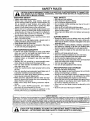
DANGER:
THIS POWER UNIT CAN BE DANGEROUS! THIS UNIT CAN CAUSE SERIOUS INJURY OR BLINDNESS
TO THE OPERATOR AND OTHERS. THE WARNINGS AND SAFETY INSTRUCTIONS IN THIS MANUAL
MUST BE FOLLOWED TO PROVIDE REASONABLE SAFETY AND EFRCIENCY IN USING THIS UNrl;,
THE OPERATOR IS RESPONSIBLE FOR FOLLOWING THE WARNINGS AND INSTRUCTIONS IN THIS
MANUAL AND ON THE UNIT. READ THE ENTIRE OPERATOR'S MANUAL BEFORE ASSEMBLING
AND USING THE UNIT! RESTRICT THE USE OF THIS UNIT TO PERSONS WHO READ, UNDERSTAND,
AND FOLLOW THE WARNINGS AND INSTRUCTIONS IN THIS MANUAL AND ON THE UNIT. NEVER
ALLOW CHILDREN TO USE THIS TOOL.
THIS UNIT IS DESIGNED
FOR LINE
TRIMMER USE ONLY. NEVER USE ANY
OTHER CUTTING ATTACHMENT
WITH
THIS UNIT* BLADES AND HEADS WITH
FLAILING DEWCES CAN CAUSE SERIOUS
INJURY,
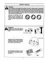
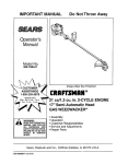
WARNING:
TRIMMER LINE CAN THROW OBJECTS
VIOLENTLY. YOU CAN BE BLINDED OR
INJURED. WEAR EYE AND LEG PROTECTION.
LEG GUARDS
EYE PROTECTION
BOOTS
HAZARD ZONE
HAZARD ZONE FOR THROWN OBJECTS.
TRIMMER LINE CAN THROW OBJECTS
VIOLENTLY. OTHERS CAN BE BLINDED
OR INJURED. KEEP PEOPLE AND ANIMALS 50 FEET (15 METERS) AWAY.
READ OPERATOR'S MANUAL. FOLLOW
ALL WARNINGS AND INSTRUCTIONS.
FAILURE TO DO SO CAN RESULT IN SERIOUS INJURY.
OPERATOR'S
MANUAL
-3-
SAFETY
LABEL
PRODUCT
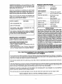
CONGRATULATIONS
on your purchase of a Sears
Craftsman Gas Weedwacker. It has been designed, engineered and manufactured to give you the best possible
dependability and performance.
SPECIFICATIONS
CUTTING PATH.................. 17" (43 cm)
TRIMMER LINE ................... 080" Diameter
Monofitament
Should you experience any problems you cannot easily
remedy, please contact your nearest Sears Service Center/Department. Sears has competent, well trained technicians and the proper tools to service or repair this unit.
SEMI-AUTOMATIC
HEAD ROTATIOnal............... Clockwise (for operator)
Please read and retain this manual. The instructions will
enable you to assemble and maintain your unit properly.
Always observe the "SAFETY RULES,"
FUEL/OIL MIX RATIO ......... 40:1 (3.2 oz. oil per
gallon gas)
MODEL NUMBER:
ENGINE ..............................
IGNITION ............................ Spark Advance
(air gap .010" to .014")
IGNITION TIMING .............. Non-adjustable, fixed
358.798430
DATE CODE/SERIAL
32 cc, 2-cycle Air-Cooled
SPARK PLUG ..................... Champion (RCJ-8Y)
NO.:
SPARK PLUG GAP .............. 025" (.6mm)
DATE OF PURCHASE:
THE MODEL AND SERIAL
FOUND ON THE PRODUCT.
ENGINE RPM ..................... 7,500 RPM Max.
NUMBER
WILL BE
SPECIAL NOTICE
For users on U.S. ForestLand and in some states, includ_
ing California (Public Resources Codes 442 and 443),
Idaho, Maine, Minnesota, New Jersey, Oregon, and
Washington:Certain internalcombustionengines operated
on forest,brush, and/or grass-coveredlands in the above
areas are required to be equipped with a +spark arrestor,
maintainedin effectiveworkingorder,or the enginemustbe
constructed,equipped,and maintainedfor the preventionof
fire.Check with yourstateor localauthoritiesfor regulations
pertainingto these requirements.Failure to follow these
requirementsis a violationof the law. This unit is not factory-equippedwitha sparkarrestor;,however,a sparkarrestor
is available as an optional part. If a spark arrestor is
required in your area, contact your SEARS Service
Center/Departmentfor thecorrectkit.
YOU SHOULD RECORD BOTH SERIAL NUMBER
AND DATE OR PURCHASE AND KEEP IN A SAFE
PLACE FOR FUTURE REFERENCE.
MAIkrrENANCE
AGREEMENT
A Sears Maintenance Agreement is available on this
product. Contact your nearest Sears store for details.
CUSTOMER
:
RESPONSIBILITIES
• Read and observe the safety rules+
• Follow a regular schedule in maintaining, caring for,
and using your unit.
• Follow the instructions under "Customer Responsibilities" and "Storage" sections of this Operator's Manual.
M_m,_ctuPed
under ot_e or more of t_e fo_,_,t_
U,S, patents:. 5,383,427;
54,387,988;
5,345,684: 5,343.831;5276,9_: 5+269,665;5,_z0,_23; 4,940,(_8; 4,897,9"23; ,8582_;
4,846,123; 4,841,929; 4,835,667; 4,825,548; 4,823,465; 4.819,742; 4,'/98+185; 4,508, 7 :
4.483o_69; 4,45t+983'. 4o366.622; 4+366,621; 4,352,243; 4,347,666; 4.290,200; 4.286+6 5;
4,236.312; 4,177+561; 4,172,322; 4,167.812; 4,16_+575; 4,16'_,820; 4,122.653; 4,104.79_
Re.32+266; {3344.088; D324+051; D304,19_: D276,t60.
Other U.S, _
!oreign p_te_
perKr_g.
FULL ONE YEAR WARRANTY ON CRAFTSMAN
GAS-POWERED
WEEDWACKER ®LINE TRIMMER.
For one year'from the date of purchase, when this Craftsman Gas-Powered WeedwackeP Line Trimmer is maintained,
lubricated and tuned up according to the operating and maintenance instructions in the Operator's Manual, Sears wilt
repair, free of charge, any defect in materials or workmanship.
This warranty excludes nylon line, spark plug, and air filter, which are expendable parts and become worn during normal use.
if this Weedwacker _ Line Trimmer is used for commercial purposes, this warranty applies for only 90 days from the date
of purchase. If this Weedwacker _ Line Trimmer is used for rental purposes, this warranty applies for only 30 days from
date of purchase. This warranty applies only while this product is in use in the United States.
WARRANTY SERVICE IS AVAILABLE BY RETURNING THE WEEDWACKER ®LINE TRIMMER TO THE NEAREST
SEARS SERVICE CENTER IN THE UNITED STATES.
This warranty gives you specific legal rights, and you may also have other rights which vary from state to state.
SEARS, ROEBUCK AND CO., DI817WA, HOFFMAN ESTATES, IL 6.0179
-4-
J_
JUUll
Ii [
Ill
I
I
IHI
III
L i
.,l,,.
,
,
,
,,,,i,,,,,
iiill
i ii
IIII
....
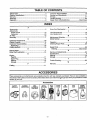
Safety Rules ....................................................................
Product Specifications ............................. _.......................
Warranty ..........................................................................
Assembly .........................................................................
Operation .........................................................................
i1,,i,,i,,11,1 HH II I J
IHI
2
4
4
7
8
Customer Responsibilities ............................................. 14
Service and Adjustments ............................................... 17
Storage ..........................................................................
21
Trouble Shooting ......... :.......:.......................................... 22
Repair Parts Ordering/Service ........................ Back Cover
I
iiii
] i
........
i111
ii
iiiiiii11[i iiiii
INDEX
'"
A
Accessories .....................................................................
5
Adjustments
Assist Handle .............................................................
10
Carburetor ..................................................................
20
Air Filter .........................................................................
15
Assembly .............................................. :.......................... 7
C
Carburetor Adjustments ................................................. 20
Carton Contents ..............................................................
6
Customer Responsibilities ............................................. 14
Spark Plug ..................................................................
15
Cutting Methods ............................................................
13
D
.Debris Shield .................... _........ :..................................... 7
Drive Shaft Lubrication .................................................. 15
E
Engine
Fue!/Oil .......................................................................
11
Spark Plug ..................................................................
15
Starting .......................................................................
12
Storage .......................................................................
2t
F
Fueling ...........................................................................
11
IIIIIIIIIIIlull]l]l]
nlllullllullll
i
K
Know Your Weedwacker .................................................. 8
L
Line Advancement .........................................................
10
Line Replacement ..........................................................
18
M
Maintenance Schedule ..................................................
14
Model Number ........... :.....................................................
4
O
Operation .........................................................................
8
Ordering Repair Parts ................................................... 26
R
Repair Parts ...................................................................
23
Ordering .......................................................
Back Cover
S
Service and Adjustments ................................ ............... 20
Specifications...................................................................
4
Starting ................. .........................................................
12
Storage ..........................................................................
21
T
Trouble Shooting ............................................................
22
W
Warranty ..........................................................................
4
1111 I
jjlllllll
111111 I
IIIIIIIIII
I
I
I
I
[llllllllrlrr
II
AccEssORIEs
Ilul
jlllllllll]llllr
I_I)
IJUIIIII
1
1
IqlLIllrlllllllllllll
I
i
I
IIIIIIIrllll
rrrl
Irl
1
These accessories and attachments were available when the unit was originally purchased. They are also available at
most Sears retail outlets and service centers. Most Sears stores can order these items for you when you provide the model
number of your unit.
_
"
Accessories
SAFETY
GOGGLES
HEARING
PROTECTION
SEMIAUTOMATIC
LINE HEAD
SPOOL
WITH UNE
BULK
UNE
80FT.
200 Flr.
400 FT.
-5-
SPARK
PLUG
AIR
FILTER
GAS
CAN
SEARS
2_CYCLE
ENGINE OIL
3-
40:1 i
.....................
_
.........................................................
CARTON
...........
i=l i
ii ,i illli,,ll
i i
,,,,,,,,,,,,,
,,,,
i i jl
ill
i
L/
I
CONTENTS
ii
ill
i
:
,.............................................
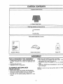
Hardware shown full size
(1) Debris Shield Knob
Parts bag contents not shown full size
Long Hex Key
Parts packed separately in carton
Plastic Debris Shield
Operator's Manual
Engine Oil
ASSEMBLY
IJ
11
I
I
III1[
I
III111
TOOLS REQUIRED
I
II
.
II
II111
....
I
FOR ASSEMBLY
• Torque Wrench (optional) - Reference torque values are
provided throughout this manual for tightening hardware.
• Long Hex Key (included)
' Adjustable wrench or large pliers
TO REMOVE
iiii i i
NOTE: Model 358.798430 is partially assembled.
• After removing the contents from the carton, chec
parts against the Carton Contents list.
• Examine the parts for damage. Do not use damage,
parts.
° Notify your SEARS store immediately if a part is miss
ing or damaged.
WEEDWACKER
NOTE: It is normal to hear the fuel filter rattle in an empt
fuel tank.
FROM CARTON
• Remove loose parts bag included with Weedwacker.
• Remove the packing material from your Weedwacker,
including the clear protective cover from the tube.
• You may use the opened packing material as a work
surface.
-6-
,,, ,,,
,,,,,,,,,,,,,,,,,,,,,,,,,,,,
,,,,,,, ,
,
, ...........................
ASSEMBLY
--
ttttttit
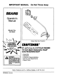
HOW TO ASSEMBLE
WEEDWACKER
ASSIST
HANDLE
YOUR
ASSEMBLY
t
ii
...,
,
......................
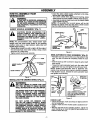
(Fig. 1)
TUBE
CAUTION:
WHEN
ADJUSTING
THE
ASSIST HANDLE FOR COMFORT, BE
SURE THAT THE ASSIST
HANDLE
REMAINS
BETWEEN
THE TRIGGER
HOUSING AND THE SAFETY LABEL.
FIGURE 1.
DEBRIS SHIELD
DEBRIS SHIELD
KNOB
SLOT
NOTE: For pre-assembled units, simply loosen assist
handle knob and rotate assist handle to the operating
position, being sure to align between safety label and
throttle trigger housing.
• Rotate assist handle from left to right to tilt the angle of
the semi-automatic head when cutting a large, slopes
area such as a ditch bank.
• Tighten assist handle knob securely.
DEBRIS SHIELD
DEBRIS SHIELD
(INSTALLED)
BRACKET
SCREW
SHOULDER
Figure 2
SEMI-AUTOMATIC
HEAD ASSEMBLY
(Fig. 3)
• Place the dust cup over the hex nut on the bottom of the
tube. The hex nut should fit completely inside the dust
cup.
• Hold the dust cup with a wrench to keep the arbor shaft
from turning
• Thread the semi-automatic head onto the arbor shaft
against the dust cup and tighten firmly with your hand.
NOTE: Unless semi-automatic head is tightened adequately, it can unthread when engine is started or stopped.
If the situation occurs, reinstall the semi-automatic head
and tighten more securely.
TUBE
SQUARE HEAD
SCREW
ASSIST
KNOB
I
• Insert the debris shield bracket, attached to the tube,
into the slot in the debris shield.
• Turn debris shield while aligning and inserting debris
shield screw into hole located in debris shield bracket.
- Assemble the debds "shield knob onto the debris shield
screw.Tighten securely.
NOTE: It is possible that a small space will be left
between the debris shield and the debds shield bracket
when the shield screws are fully tightened.
ASSmT
Figure 1
INSTALUNG
THE DEBRIS
SHIELD (Fig. 2)
WARNING:
TUB
I
THE UNE UMITER IS SHARP AND CAN
CUT YOU. BE SURE TO WEAR GLOVES
WHILE WORKING WITH THE LINE MMITER.
HEX.---"P
NUT J
THE DEBRIS SHIELD MUST BE PROPERLY
INSTALLED
FOR ALL LINE TRIMMER
USAGE. THE DEBRIS SHIELD PROVIDES
PARTIAL PROTECTION FROM THE RISK
OF THROWN OBJECTS TO THE OPERATOR AND OTHERS.
ARBOR
USE A WRENCHTO HOLD THE
DUSTCUP WHILE SPINNING
THE SEMI-AUTOMATICHEAD
ONTHE UNIT
SHAFT
,
CHECK
DO NOT ALTER
OR REMOVE
THE
TAB ON THE SHIELD BRACKET. WHEN
INSTALLED CORRECTLY, THE BRACKET
TAB ENSURES PROPER DEBRIS SHIELD
AUGNMENT. FAILURE TO INSTALL THE
DEBRIS SHIELD IN POSITION SHOWN IN
ILLUSTRATION CAN RESULT IN SERIOUS
INJURY TO THE OPERATOR.
Figure 3
LIST
° Check all fasteners, make sure they are tight and there
are no loose parts.
• Check to make sure the throttle cable is positioned correctly.
• With the unit held in the operating position, adjust the
assist handle up or down the tube for best comfort and
balance before first use.
-
-7-
ill.
iill
i
illl
ii
iiill
i
•
.... : ................
i ,.HI.
IIIIlllI
JI
I
i
OPERATION
_-
i,,,m i
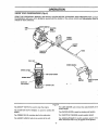
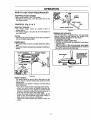
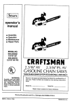
KNOW YOUR WEEDWACKER
ii i
(Fig. 4)
READ THIS OPERATOR'S MANUAL AND SAFETY RULES BEFORE OPERATING YOUR WEEDWACKER. Compar
the illustrations with your unit to familiarize yourself with the location of the various controls and adjustments. Save thi
manual for future reference.
STARTER
ROPE
4ANDLE
CAP
ASSIST
HANDLE
SAFETY
FOAM
GRIP
TUBE
THROTTLE
TRIGGER
FUEL CAP
DEBRIS SHIELD
CHOKE LEVER
AIR RLTER COVER
PRIMER
UNE
UMITER
MUFFLER
AND GUARD
SEMI-AUTOMAT
HEAD
SPARK PLUG
Figure 4
The ON/OFF SWITCH is used to stop the engine,
The LINE LIMITER cuts trimmer line automatically
correct length,
The STARTER ROPE HANDLE is used for starting the
engine,
to th_
The CHOKE LEVER is used for starting cold engine.
The PRIMER BULB circulates fuef to the carburetor.
• The THROTTLE TRIGGER cbntrots engine speed.
The ASSIST HANDLE aids in the control of the unit.
The SEMI-AUTOMATIC
HEAD contains spool of lin_
which advances when head is tapped on the ground.
-8-
OPERATION
LINE TRIMMER
_
SAFETY
SAFETY
WARNING:
BE THROWN VIOLENTLY.THE DEBRIS SHIELD WILL
NOT PROVIDE COMPLETE PROTECTION TO THE
OPERATOR OR OTHERS.THE
OPERATOR MUST
WEAR A SAFETY FACE SHIELD OR GOGGLES.
ALWAYS WEAR HEAVY, LONG PANTS AND BOOTS.
KEEP OTHERS AT LEAST 50 FEET (15 METERS)
AWAY.
LeGGUARDS
|
FACE
SHIELD
THIS UNIT WILL THROW OBJECTS AND CUT. KEEP
OTHERS INCLUDING CHILDREN, ANIMALS, BYSTANDERS AND HELPERS AT LEAST 50 FEET (15
METERS) AWAY FROM THE OPERATOR AND UNIT.
STOP THE ENGINE IF YOU ARE APPROACHED. IN
AREAS WHERE OTHER PEOPLE AND ANIMALS
ARE PRESENT
SUCH AS NEAR SIDEWALKS,
STREETS, HOUSES, ETC., IT IS STRONGLY RECOMMENDEDTHATTHE
OPERATOR USE THE BUDDY
SYS_M;THAT
IS, HAVE ANOTHER PERSON SERVE
AS A "LOOK-OUT", KEEPING HIMSELF AND OTHERS AT LEAST 50 FEET (15 METERS) AWAY FROM
THE OPERATOR.
ZONE
N
SEMI'AUTOMATIC HEAD
SEMI-AUTOMATIC
HEAD
PARTS THAT ARE
CHIPPED, CRACKED OR DAMAGED IN ANY OTHER
WAY CAN FLY APART AND CAUSE SERIOUS
INJURY. DO NOT USE. REPLACE DAMAGED PARTS
BEFORE USING THE UNIT.
OPERATOR
THROWN
USE ONLY GOOD QUALITY
REPLACEMENT PARTS
UNIT SAFETY
SAFETY
• Always wear eye protection when operating, servicing,
or performing maintenance on your unit. Refer to
"Accessodes."
• Do not operate this unit when you are tired, ill, or under
the influence of alcohol, drugs or medication.
• Always wear heavy, long pants, long sleeves, boots and
gloves. Do not go barefoot or wear sandals, short pants.
Loose clothing or jewelry, or clothing with loosely hanging straps, ties, tassels, etc. can be caught in moving
parts. Secure hair so it is above shoulder length. Being
fully covered will help protect you from pieces of toxic
plants such as p6ison ivy thrown by the semi-automatic
head, which could be more of a hazard than touching
the plant itself.
• Do not swing the unit with such force that you are in
danger of losing your balance.
• Never start or run the engine inside a closed room or
building. Breathing exhaust fumes can kill.
• Keep handles free of oil and fuel.
-9-
• Inspect the entire unit before each use. Replace damaged parts. Check for fuel leaks and make sure all fasteners are in place and securely fastened.
• Use only .080" diameter good quality monofilament
line. Never use wire or rope, string, etc.
• Be sure the debris shield is propedy attached.
• Make sure semi-automatic head is propedy installed
and securely fastened. Refer to =Assembly."
• Make carburetor adjustments with the drive shaft housing supportedTo pr,tvent the semi-automatic head from
contacting any object.
° Keep others away when making carburetor adjustments.
• Use only good quality Sears accessories or attachments.
CUTTING
SAFETY
• Inspect the area to be cut before each use. Remove
objects (rocks, broken glass, nails, wire, string, etc.)
which can be thrown or become entangled in the semiautomatic head.
• Always keep the ,engine on the right-hand side of your
body,
• Hold the unit firmly with both hands.
• Keep firm footing and balance. Do not over-reach.
• Keep the semi-automatic head below waist level,
• Do not raise the engine above your waist,
• Keep all parts of your body away=from the semi-automatic head and muffler when engine is running.
• Use only for jobs explained in [his manua!.
• Cut at full throttle.
• Cut from your right to your left.
OPERATION
HOW TO USE YOUR WEEDWACKER
STOPPING
YOUR ENGINE
, Move on/off switch to the "Off" position.
°ff engine does not stop, move the choke lever to the
full choke position
ASSIST
HANDLE
SAFETY LABEL
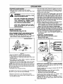
CONTROLS
TUBE
(Fig. 5, 6 & 7)
THROTTLE TRIGGER
° The throttle trigger allows for variable control of
engine speed.
• The throttle trigger is actuated by the index finger on
your right hand.
CHOKE
• The choke is set by moving the choke lever up fully for
cold or refueled engine starts.
PRIMER BULB
The primer bulb is used to circulate fuel to the carburetor.
• The primer bulb is activated by pressingon it with your
thumb.
Choke Positions
_
ASSIST HANDLE KNOB
Figure 6
TRIMMER LINE ADVANCE
Your Weedwacker is equipped with a semi-automatic
trimmer head. The most efficient line length is the
maximum length allowed by the line limiter.
TO ADVANCE THE LINE:
• _Operatethe engine at full throttle.
Hold the semi-automatic head parallel to and above
a grassy area.
, Tap the bottom of the semi-automatic head lightly_
on the ground one time. Approximately 2 inches of
line will be advanced with each tap.
ThrottleTrtgger
TO ADVANCE LINE,
TAP BOTTOM OF
SEMI-AUTOMATIC
HEAD ON GROUND
ONE TIME
UNE LIMITER
:
Primer
Bul"''-b-'"--
F
!
__t
Figure 7
Figure 5
ASSIST HANDLE
The assist handle is used to aid in the control of the
unit, as well as a barrier between the operator and the
cutting head.
TO ADJUST THE ASSIST HANDLE FOR BALANCE
AND CONTROL:
• Turn off the engine before adjusting assist handle.
• Adjust the assist handle by slightly loosening the
assist handle knob and rotating the assist handle
forward or backward. Adjust the assist handle up or
down the tube (but above the safety label).
• Rotate the assist handle from left to right to tilt the
angle of the semi-automatic head when cutting a
large, sloped area such as a ditch bank.
• Tighten the assist handle knob before starting the
engine.
-10-
i
i ii
iiiii ii,l,llll
,,,,,,,,,,,,,,,,,, ,,,,,,,,,,,,, ,,
,
OPERATION
3J
BEFORE STARTING
I
II II
II
IIIIIIIIII
J
:
IIJIIIIIIIIIIIIIIIIIIIIIIIIIIIIIII
ENGINE:
:
40:1 2-CYCLE
AIR-COOLED
:
IIII
ENGINE
IIIIIII
I
IIIIIIIIIIII
I
IIII
OIL
CRAFTSMAN 40:1 2-cycle engine oil (AIR-COOLED) is
strongly recommended. This oil is specially blended with
fuel stabilizers for increased fuel stability (extends fuel life
up to 5 times longer) an'dreduced smoke.
WARNING:
BE SURE TO READ THE FUEL SAFETY
INFORMATION
IN THE SAFETY RULES
SECTION ON PAGE 2 OF THIS MANUAL
BEFOREYOU BEGIN.
If CRAFTSMAN 40:1 2-cycle engine oil (AIR-COOLED)
is not available, use a good quality 2-cycle engine oil
(AIR-COOLED) that has a recommended fuel mix ratio of
40:1.
IF YOU DO NOT UNDERSTAND THE FUEL
SAFETY SECTION DO NOT ATTEMPT TO
FUEL YOUR UNIT; SEEK HELP FROM
SOMEONE WHO DOES UNDERSTAND
THE FUEL SAFETY SECTION OR CALL
THE CUSTOMER ASSISTANCE HOTLINE
AT 1-800-235-5878.
IMPORTANT! Do no use:
• AUTOMOTIVE OIL
- BOAT OILS (NMMA, BIA, etc.)
GASOLINE
The two-cycle engine on this product requires a fuel mixture of regular unleaded gasoline and a high quality 40:1
2-cycle engine oil (AIR-COOLED)for lubrication of the
bearings and other moving parts.The correct fuel/oil mixture is 40:1 (see Fuel Mixture Chart). Too little oil or the
Incorrect oil type will cause poor performance and may
cause the engine to overheat and seize.
These oils do not have proper additives for 2-cycle
engines (AIR,COOLED) and can cause engine damage.
GASOLINE
AND OIL MIXTURE
Mix gasoline and oil as follows:
° Consult chart for correct quantities.
° Do not mix gasoline and oil directly in the unit's fuel
tank.
Gasoline and oil must be premixed in a clean approved
fuel container. Always use fresh regular unleaded gasoline.
FOR ONE GALLON:
• Pour 3.2 ounces of high quality, 40:1 2-cycle engine oil
(AIR-COOLED) into an empty, approved one gallon
gasoline container.
° Add one gallon of regular unleaded gasoline to the gallon container, then securely replace the cap.
° Shake the container.
° The mixture is now ready for use. Fuel stabilizer can be
added at this time if desired; follow mixing instructions
on the label.
This engine is certified to operate on unleaded gasoline.
IMPORTANT: Experience indicates that alcohol blended
fuels called gasohol (or using ethanol or methanol) can
attract moisture, which leads to oil/gas separation and
formation of acids during storage. Acidic gas can damage the fuel system of an engine while in storage. To
avoid engine problems, the fuel system should be emptied before storage for 30 days or longer. Drain the gas
tank, then run the fuel out of the carburetor and fue! lines
by starting the engine and letting it run until it stops. Use
fresh fuel next season. See STORAGE instructions for
additional information. Never use engine or carburetor
cleaner products in the fuel tank or permanent damage
. may occur.
FUEL MIXTURE
CHART
40:1 Fuel:Oil Mix Ratio
Gasoline
l"_aUo5
2.5 gallons
Oil (fL oz.)
3.2
8.0
FUEL STABILIZER
NOTE: Fuel containers may hold more than the specified
amount. If too much gasoline is in the container, the
resulting gas-to-oil fue! mixture will not be correct for
proper engine operation.
Fuel stabilizer is an acceptable alternative in minimizing
the formation of fuel gum deposits during storage. Add
stabilizer to gasoline in fuel tank or storage container.
Always follow the fuel tank or storage container. Always
follow the fuel mix ratio found on the stabilizer container.
Run engine at least 5 minutes after adding stabilizer to
allow the stabilizer to reach the carburetor. You do not
have to drain the fuel tank for storage if you are using
fuel stabilizer.
CRAFTSMAN 40:1 2-cycle engine oil (AIR-COOLED) is
specially blended with fuel stabilizers. If you do not use
this Sears oil, you can add a fuel stabilizer (such as
CRAFTSMAN No. 33500) to your fuel tank.
-11
-
OPERATION
iill
STOPPING
YOUR ENGINE
• Move the ON/OFF switch to the OFF position.
• If engine does not Stop, move the choke lever down
(full choke).
FOR SAFE STARTING AND OPERATION,
FOLLOW ALL SAFETY PRECAUTIONS IN
THIS
OPERATOR'S
MANUAL
AND
LABELS ON THE UNIT. DRESS PROPERLY BEFORE STARTING ENGINE.
AVOID ANY CONTACT WITH THE MUFFLER. A HOT MUFFLER CAN CAUSE
SERIOUS BURNS.
(Fig. 8 & 9)
COLD ENGINE START AND WARM ENGINE
START AFTER RUNNING OUT OF FUEL
• Fue! engine with 40:1 fuel mix (3.2 oz. to 1 gal. gas).
Move 10 feet (3 meters) away from fueling site.
STARTING
/
k
_
, ......................
onds at =Off Choke,"then release the throttle tdgger.
.
NOTE: If engine dies with the choke lever at the"Off Choi_
position, move the choke lever to half choke and pull the
rope until the engine runs.Allow the unitto run for 30 more
seconds at=off Choke,"then release the throttletrigger.
,, To stop the engine, move the ON/OFF switch to the
OFF position.
STARTING
PROCEDURE
ill /I
NOTE: If the engine has not started after 6 pulls (at hal
choke), check to make sure the ON/OFF switch and the
choke lever are in the proper positions. Then, move th_
choke lever to the full choke position and press the prime
bulb 6 times; pull the starter rope 2 more times. Move the
choke lever to half choke and pull the starter rope until thl
engine runs, but no more than 6 more pulls.
NOTE: If engine still has not started, it is probably flcodec'
Proceed to "Difficult Starting and Flooded Engine."
• Allow the engine to run 10 seconds, then move the chot_e
lever to off choke. Allow the unit to run for 30 more sec-
THE
SEMI-AUTOMATIC HEAD WILL TURN
WARNING:
WHEN THE ENGINE STARTS.
BASIC
I,HI, III
Once the engine starts, allow the engine to run 10 sec
onds, then move the choke lever to =Off Choke." Allow th,
engine to run for 30 more seconds at "Off Choke" befor
releasing the throttle tdgger.
POSITION
STARTING
A WARM ENGINE
• Move choke lever to the "Off Choke" position.
• Squeeze throttle trigger.
,, Pull starter rope until engine starts.
ON/OFF
SWITCH
i HH Illl'
Figure 8
• Move the ON/OFF switch to the ON position.
° Prime engine.by pressing primer bulb six times.
• Actuate choke by moving the choke lever to the "Full
Choke" position.
° Rest engine and debris shield on ground, supporting
semi-automatic head off ground.
• Squeeze and hold the throttle trigger. Keep the throttle
trigger fully squeezed until the engine runs smoothly.
NOTE: When pulling the starter rope, do not use the full
extent of the rope as this can cause the rope to break.
Do not let the starter snap back. Hold the handle and let
the rope rewind slowly.
• Pull starter rope sharply five times.
The engine may sound as if it is trying to start before the
fifth pull. If so, go to the next step immediately.
• Move the choke lever to the "Half Choke" position.
• Pull the starter rope sharply until the engine runs, but
no more than six pulis.
Figure 9
DIFFICULT
STARTING
OR FLOODED
ENGINE
The engine may be flooded with too much fuel if it has
not started after 20 pulis.
Flooded engine's can be cleared of excess fuel with the
following procedure:
• Move the choke lever to the "Off Choke" position.
• Squeeze and hold the throttle trigger.
° Pull starter rope handle until engine starts.
Starting could require pulling starter rope handle many
times depending on how badly unit is flooded.
If engine still fails to start, refer to "TROUBLE SHOOTING" chart or call the 1-800 number listed on the front
cover of this manual.
-12-
ill ii ii IH
.......
OPERATION
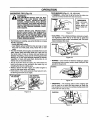
OPERATING
i_
TIPS
(Fig.
10)
USE MINIMUM
SPEED AND DO NOT
WARNING:
CROWD THE LINE WHEN CUTTING
AROUND
HARD
OBJECTS (ROCK,
GRAVEL, FENCE POSTS, ETC.), WHICH
CAN DAMAGE THE SEMI-AUTOMATIC
HEAD, BECOME ENTANGLED IN THE
LINE, OR BE THROWN CAUSING A SERIOUS HAZARD.
TECHNIQUES
(Fig. 11, 12, 13 & 14)
* TRIMMING - Allow only the tip of the line to make contact. Do not force trimmer line into work area.
TRIMMING
REMEMBER
Keep semi-automatic
head
3
inches above the
ground while trimming.
J
3 INCHES
ALWAYS WEAR
EYE PROTECTION.
NEVER LEAN OVER THE SEMI-AUTOMATIC HEAD. ROCKS OR DEBRIS CAN
RICOCHET OR BE THROWN INTO EYES
AND FACE AND CAUSE BLINDNESS OR
OTHER SERIOUS INJURY:
• For tdmming or scalping, use partial throttle to increase
line life, especially:
- dudng light duty cutting.
- near objects around which the line can wrap or wear
line such as small posts, trees, fence wire or concrete.
-. The line will easily remove grass and weeds from around
walls, fences, trees and flower beds; but, it also can cut
the tender bark of trees or shrubs and scar fences and
damage vinyl siding, above ground swimming pool metal
skirting, etc.To help avoid damage especially to delicate
vegetation or trees with tender bark, shorten line to 4-5
inches and use at partial throttle.
• The tip of the line does the cutting.You will achieve the
best performance and minimum line wear by not
crowding the line into cutting area.
• Always release throttle trigger and allow engine to
return to idle speed when not cutting.
• Hold bottom of the semi-automatic head about 3 inches above ground and at an angle.
TIP OF LINE DOES
THE CUTTING
Figure 11
• SCALPING -The scalping technique removes unwanted vegetation. Allow the tip of the line to strike the
ground around trees, posts, monuments, etc. This technique increases line wear.
SCALPING
""
_
3 INCHES
Figure 12
, MOWING - Your trimmer is ideal for mowing in places
conventional lawn mowers cannot reach. Keep the line
parallel to the ground.
MOWING
UNE CROWDED
INTO WORK AREA
Figure 13
RIGHT
3INCHES
• SWEEPING - The fanning action of the rotating line
can be used for a quick and easy clean up. Keep the
line parallel to and above the surfaces being swept and
move unit from side to side.
WRONG
Figure 10
Figure 14
- 13-
CUSTOMER
MAINTENANCE
RESPONSIBILITIES
SCHEDULE
Fil! in dates as you complete regular service
......ill
,,v,........................
,,, J, ,
Before
Use
Every Every
5 Hrs. 25 Hrs
Yearly Service Dates
,
Check for damaged or worn parts
Check for loose fasteners &..........................
parts
i.....
Clean unit & labels
After
Use
,I
,,,,,,,,,, ,,
_"
,
J
,/
Clean air filter .......................
Drive Shaft Lubrication
J,,,,,,,,,,,,,,_
_,
,/
Cleanilnspect.'.iSp'ark A_;sto'[ Screen (.if.!.n.stalied)and Muffler
I
1
"/
Replace spark plug
v"
Replace fuel filter
v"
,,,,,,,,,,,
_,,, ,,j,
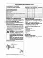
GENERAL
RECOMMENDATIONS
BEFORE EACH USE
The warranty on this unit does not cover items that have
been subjected to operator abuse or negligence. Io
receive full value from the warrant]€,the operator must
maintain unit as instructed in this manual.
Some adjustments will need to be made periodically to
properly maintain your unit.
All adjustments in the "Service and Adjustments"section of
this manual should be checked at least once each season.
° Once a year, replace the spa_k plug, replace air filter
element and semi-automatic head for wear. A new
spark plug and a clean/new air filter element assures
proper air-fuel mixture and helps your engine run better
and last longer.
• Follow the maintenance schedule in this manual.
WARNING
DISCONNECT THE SPARK PLUG BEFORE
PERFORMING MAINTENANCE
EXCEPT
FOR CARBURETOR ADJUSTMENTS.
REPLACE SEMI-AUTOMATIC HEAD PARTS
THAT ARE CRACKED, CHIPPED, OR DAMAGED tN ANY OTHER WAY BEFORE USING
THE UNIT.
FOR LOOSE
FASTENERS
AND
PARTS
°
•
•
•
•
•
•
Semi-automatic head
Assist handle
Throttle handle
Cylinder cover and rear shroud
Air filter cover
Muffler
Line Limiter
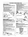
CLEAN UNIT AND LABELS
DRIVE SHAFT
O General purpose lithium base grease.
CHECK
• Clean the unit using a damp cloth with a mild detergent.
• Wipe off the unit with a clean dry cloth.
CHART
Q
• Semi-automatic head - replace semi-automatic head
parts that are bent, warped, cracked, or damaged in
any way.
• Fuel cap - replace broken or leaking fuel cap.
• Debris shields - replace debds shields that are bent,
warped, cracked, or damaged in any way.
• Line iimiter - missing or damaged.
AFTER USE
INSPECT THE ENTIRE UNIT. REPLACE
DAMAGED PARTS. CHECK FOR FUEL
LEAKS AND MAKE SURE ALL FASTENERS
ARE IN PLACE AND SECURELY FASTENED.
LUBRICATION
CHECK FOR DAMAGED OR WORN PARTS
-14-
CUSTOMER
EVERY
5 HOURS
CLEAN
AIR RLTER
RESPONSIBILITIES
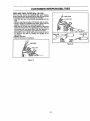
DRIVE SHAFT LUBRICATION
(Fig. 15)
•
A dirty air filter decreases the life and performance of the
engine and increases fuel consumption and harmful emissions.
Always clean after 5 tanks of fuel or 5 hours of operation.
Clean more frequently in dusty conditions.
• Loosen the screws on the air filter cover enough to
remove the cover from the engine,
• Remove air filter from cover.
solution of dish washing liquid.
Rinse air filter thoroughly in clean water.
i _ueeze
ash filterairinfilter
warm
water. We
recommend a mild
drysoapy
and replace
in cover.
Re-install the air filter cover, making sure the choke exit
slot is placed over the choke lever.
*
.
°
°
(Fig. 17)
Loosen the nose cone screws.
Remove the tube from the nose cone.
Remove the drive shaft from the tube.
Check drive shaft for broken wires, twists or kinks, and
replace if damage is found.
o Usinga clean cloth, wipe surface of drive shaft thoroughly to remove any grease or dirt.
° Apply a uniform coat of lithium base grease to the entire
surface of the drive shaft.
top of the tube.
i Replace
nject thedrive
remaining
shaft in
contents
the tube.
of the grease tube into the
Re-assemble the tube in the nose cone. Tighten screws
securely.
J
Figure 15
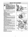
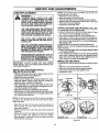
EVERY 25 HOURS
__
CLEAN AND INSPECT SPARK ARRESTOR
SCREEN AND MUFFLER (Fig, 16)
As the unit is used, carbon deposits build up on the muffler
and spark arrestor screen (if installed), and must be
removed to avoid creating a fire hazard or affecting engine
performance.
Required cleaning is every 25 hours of operation or annually, whichever is less.
Replace the spark arrestor screen if breaks occur.
CLEANING THE SPARK ARRESTOR SCREEN
° Loosen and remove the 2 muffler guard screws.
DRIVE SHAFT
Figure 17
YEARLY
REPLACE SPARK PLUG (Fig. 18)
The spark plug.,_houldbe replaced each year to ensure the
engine starts easier and runs better. Sark plug gap should
be .025.
Remove
Remove the
the muffler
muffler cover
guard. retaining springs.
Remove muffler diffuser and spark arrestor screen
assembly. Notice the orientation of these parts for
reassembly.
Remove spark plug from cylinder and discard.
Replace with correct spark plug and re-tighten with spark
Twist,
then pull
of spark
plug boot.
I_lug wrench
(! 0-12
ft.lbs.)
Reconnect spark plug boot.
replace if breaks are found in the screen.
Replace any broken or cracked parts.
i Clean
thediffuser
spark and
arrestor
a wire
brush or
Reinstall
sparkscreen
arrestorwith
screen
assembly.
Reinstall muffler cover and the two muffler cover retaining springs.
° Reinstall muffler guard and the two muffler guard screws
(15-20 ft.lbs.)
..__.._____.--.. SPARK PLUG
SPARK PLUG
BOOT
Figure 18
Figure 16
- 15 -
CUSTOMER
REPLACE
RESPONSIBILITIES
FUEL FILTER (Fig. !9 & 20)
The fuel filter should be replaced alter each season.
Never operate your unitwithout a fuel filter. Be careful not
to damage fuel line while removing the fuel filter.
° Run fuel tank dry of fuel before proceeding with this
step.
° Remove fuel cap and allow it to hang to side of motor.
• Using a small pair of needle nose pliers, grasp fuel cap
retainer, holding it in tank opening and putt out.
• With cap out of tank, use a small section of bent wire
similar to that shown in the illustrationto catch fuel line
and slowly putl from tank. When fuel filter appears in
opening, grasp with fingers and remove from tank.
° Once filter is out of tank, hold fuel line close to fuel fitter. Remove fuel filter by twisting and pulling at the
same time.
° Replace fuel filter.
• Revers E process for installation.
FUEL LINE
FUEL RLTER
FUEL LINE
BARREL
ER
RLTER
NECK
Figure 20
Figure 19
-16-
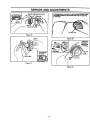
SERVICE AND ADJUSTMENT
STARTER
ROPE (Fig. 21, 22 & 23)
DANGER:
DO NOT REMOVE THE RETAINING TAB
AND SCREW
OR THE PULLEY. THE
SPRING
BENEATH
TIIE PULLEY IS
UNDER TENSION AND CAN FLY OUT
AND CAUSE SERIOUS INJURY. IF ANY
PART OF PULLEY HOUSING ASSEMBLY
IS DAMAGED (OTHER THAN ROPE), DO
NOT USE UNIT.TAKE IT TO YOUR SEARS
SERVICE CENTER/DEPARTMENT.
FRONT
SHROUD
NOSECONE
:SHROUDSCREWS
• Disconnect spark plug wire,
• Remove the screw and nut from the throttle trigger
housing.
° Hold throttle trigger away from the foam grip and
remove the barrel end of the throttle cable from the
throttle trigger.
• Carefully pull throttle cable out of foam gdp,
• Remove tube from nose cone.
. Remove Rose cone screws.
° Remove clutch shroud screws.
° Separate nose cone from engine,
° Remove the rope retainer screw and remove any
remaining rope.
° Turn pulley clockwise as far as it will go.Then, turn the
pulley counterclockwise until the pulley notch is aligned
with the housing notch. Next, turn the pulley one complete turn counterclockwise until the notches are
aligned again,
• Insert the small hex key into the hole formed by the
notches to hold the pulley in position.
° Use a 42" length of replacement rope.
° Move away 10 feet (3 meters) from the fue! tank with
the replacement rope. Use a match and melt both ends
of the rope to prevent fraying.
° Insert one end of rope through handle and secure with
a knot. Leave a 3/16" pigtail behind knot.
° Insert the other end of the rope through the rope exit
hole into the inside of the housing, into the pulley and
up through the pulley hole,
° Wrap rope counterclockwise around the pulley ratchet
and tuck loose-end under rope where it comes out of
the pulley hole. Leave a 1" tail laying flat on top of the
pulley between the retainer rib and the retainer screw/
post.
° Install the rope retainer screw in the screw post.
° Pull firmly on the rope to tighten it against the pulley
ratchet. The rope tail must not extend beyond the
raised circle on the pulley to prevent interference with
the retaining tab.
• Hold rope taut at rope exit hole so it will not move;
remove hex key.
° Slowly feed rope into the pulley housing.
• To reassemble, reverse the above steps.
-17-
WIRE
Figura 21
I_q_.-,.;ROPE
RETAINER
SCREW
PULLEY
Figura 22
5/32"HEX
PULLEY
RETAINING
TAB AND
RIB
PULLEY
RATCHET
CIRCLE
NOTCH
Figura 23
J
,,11,,,,,
...................
,,
,
, •
,,,,,,,,,,,,,,,,.........................,,,
,
.....
..........................
SERVICE
.
_1
II
II
L
I
=11[
I
IIII
........................
II
II
II
IIII
....
..........
ii
/ILl
IIII
IIIIIIIJIII
III
I
II
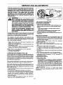
NOTE: If tap button gets knocked out of the hub,
reassemble parts as follows:
• Remove the cover and spool.
• Place the spring in the hub cylinder.
• Place the tap button over the spring and hub cylinder.
• Align the slots in the tap button with the fins in the base
of the hub. Push parts together.
• Reinstall the spool and cover.
TRIMMER
ARNING: HEAD PARTS THAT ARE
CHIPPED, CRACKED, BROKEN, OR DAMAGED IN ANY OTHER WAY CAN FLY
APART AND CAUSE SERIOUS INJURY.
DO NOT USE. REPLACE
DAMAGED
PARTS BEFORE USING THE UNIT.
INSTALLING
THE LINE SAVER MUST BE INSTALLED
ONLY FROM THE INSIDE OF THE HUB. IF
INSTALLED ON THE OUTSIDE OF THE
HUB, THE LINE SAVER CAN FLY OFF
AND BECOME A DANGEROUS MISSILE.
NEW LINE ON SPOOL (Fig. 29)
To replace the line on existing spool:
• Follow "Installing Spool with Line Already Wound" steps
and remove any line remaining on the spool.
• Use a 25 foot length of SEARS .080" diameter line.
• Insert about 1/4 inch of the end of the line through the
hole in the top or rim of the spool. Allow no more than 1/4
inch of line to extend beyond the rim to avoid interference
with tapping action.
• Wrap the line on the spool as shown by the arrow.
NOTE: The line must be wrapped firmly and evenly for
proper line feed.
° Follow •Installing Spool with Line Already Wound" steps
to complete assembly.
• If line breaks off or backs up in the semi-automatic
head, follow "Installing Spool with Une Already Wound"
steps. Pull slack in line until the line is tightly wound on
spool, leaving 4-6 inches of extended line.
USE ONLY .080" DIAMETER
GOOD
QUALITY LINE. NEVER USE WIRE, ROPE,
STRING, ETC.
USE ONLY SPECIFIED SEARS REPLACEMENT PARTS. USE OF OTHER BRANDS
OF REPLACEMENT PARTS CAN CAUSE
DAMAGE TO YOUR UNIT OR INJURY TO
THE OPERATOR OR OTHERS.
DAMAGE/INJURY" CAUSED BY USE OF
ACC ESS CRIES/ATTACH
M ENTS NOT
SPECIFICALLY
RECOMMENDED
BY
SEARS WILL NOT BE REIMBURSED.
INSTALLING
IMPORTANT: ALWAYS CLEAN DIRT AND DEBRIS
FROM SPOOL AND HUB WHEN PERFORMING ANY
TYPE MAINTENANCE.
INSTALLING PRE-WOUND
(Fig. 24, 25, 26, 27 & 28)
UUUllll
AND ADJUSTMENTS
LINE REPLACEMENT
_
_ i
THE SPOOL
• Insert line into line exit hole in the hub as shown. Figure
26.
• Align the line and notch with the line exit hole.
• Push spool into the hub until it snaps into place.
• Pull the end of the line to seat spool in hub.
• Reinstall the cover.
SPOOL
• Hold the semi-automatic head as shown. Press the two
lock tabs and remove cover.Figure 24.
• Remove the cover and spool.
• Clean dirt and debris from all parts. Replace the spool
when the square corners on the tugs are rounded off,
reduced in size, or broken off. Figure 25.
• Find THIS SIDE UP" on spool and catch the line in the
notch inthe bottom ring of the spool, leaving about 4 inches of line hanging from the spool.
• Insert the end of the line through the line exit hole.
• Align the line and notch with the line exit hole. Place spool
in hub. Make sure trimmer line is not caught between the
rim of the spool and the hub.
LOCK TAB
SPOOL
COVER
HUe
LOCK TAB
NOTE: To set the spool in the hub, it may be necessary
to pull the line through the line exit hole until the spool
drops into place.
Figure 24
• Align the lock tabs on the cover over the catches on
the hub. Push the cover down onto the hub until the
parts snap together.
• Check to make sure the lock tabs are properly fastened
as shown.
• Obtain the correct line length (4-6 inches) by pressing
the tap button
and pulling
on the line again.
Approximately 2 inches of line can be pulled each time
the tap button is pressed.
NORMAL LUGS
WORN LUGS
Figure 25
-18-
....................
SERVICE
i
AND ADJUSTMENTS
COVER RNGER OVER NOTCH
APPROXIMATELY 2 INCHES OF LINE CAN BE PULLED FROM
THE SEMI-AUTOMATIC HEAD EACH TIME THETAP BUTTON
IS PRESSED.
UNE EXIT HOLE
TAP BUTTON
Figure 26
cA:rc_
Figure 28
WRAP AS
• SHOWN BY
ARROW ON
Hue
114"OF
UNE
TAB SEATED
IN CATCH
LOCK TABS
INNER
RIM
Figure 27
Figure 29
-19-
i
SERVICE
AND ADJUSTMENTS
Carburetor adjustment is critical and if done improperly can permanently damage the engine as well as the
carburetor. Please read all/nstructions and consult the
Troubleshooting section of this manual before beginning this process. If the engine does not operate
according to these instructions after repeating the
adjusting steps, do not use the unit. For further assistance, please call our customer assistance hoUine at
1-800-235-5878.
MIXTURE SCREW
WARNING:
MAKE CARBURETOR ADJUSTMENTS WITH
THE LOWER END SUPPOR_D
TO PREVENT
SEMI-AUTOMATIC HEAD FROM CONTACTING
ANY OBJECT. HOLD UNIT WITH YOUR HAND.
THE SEMI-AUTOMATIC HEAD WILL BE SPINNING DURING MOST OF THIS PROCEDURE.
WEAR YOUR PROTECTIVE EQUIPMENT AND
OBSERVE ALL SAFETY PRECAUTIONS.
IN MIXTURE ADJUSTMENT, RECHECK IDLE
SPEED AFTER EACH ADJUSTMENT. THE
SEMI-AUTOMATIC HF-_D MUST NOT MOVE AT
IDLE SPEED,
If engine does not start, it may be flooded. If in doubt read
.the section on flooded engine in (he starting section of this
manual prior to beginning any adjustments,
The carl_Jretor has been adjusted at the factory for sea
level conditions. Adjustments may become necessary ifthe
unit is used at significantly higher altitudes or if you notice
any of the following conditions:
• Engine will not idle. See "Idle Speed Adjustment" and
"Mixture Speed Adiustment'.
• Engine dies or hesitates when it should accelerate. See
"Acceleration Check".
• Loss of cutting power which is not corrected by air filter
cleaning. See "Mixture Speed Adjustment".
NOTE: There are two adjustments on the carburetor.
* The Idle Speed Adjustment.
The Mixture Adjustment.
CARBURETOR
PRESETS
(FIG. 30)
!f your engine will not start due to suspected improper carburetor adjustment, the following presets may be required.
- If used, it is;recommended that al| steps withing the adjustment procedure be completed in order to assure a property set carburetor. If presets are not needed, proceed to section "Idle Speed Adjustment".
When making adjustments, be careful not to force the plastic limiter caps beyond the stops or damage will occur.
Very small adjustments can affect engine performance, it is
important to make slight adjustments and test performance
before proceeding. Each adjustment should be no more
than 1t16th of a turn.
• Turn the mixture adjustment fully counterclockwise to the
limiter cap stops+
; Turn idle speed adjustment clockwise one full turn.
If engine fails to start after performing carburetor presets,
the unit may be flooded. Review the "Difficult Starting"
section of the manua!+ If problems continue, call the 1800 number listed on the front cover of this manual for
further assistance.
• Start the engine and operate for three (3) minutes to
warm up. Go to "Adjusting Procedure".
- 20 -
SCREW
COVER
Figure 30
ADJUSTING
PROCEDURE
iDLE SPEED ADJUSTMENT
• Allow the warm engine to idle.
• Adjust the idle Speed until the engine continues to run
without stalling and without the semi-automatic head
turning.
- Turn screw clockwise to increase engine speed ff
engine stalls or dies.
- 7[lrn screw counte_l_=_'se to slow engine down.
• Follow instructionsin _cceleration Check".
o No further adjustments are necessary if performance is
satisfactory.
MIXTURE ADJUSTMENT
• Support the lower end so the semi-automatic head is off
the ground and will not make contact with any object. Be
sure the trimmer line is extended to the maximum length
allowed by the line limiter.
• Start the engine. Allow engine to idle, then squeeze
throttle trigger fully.
NOTE: Perform steps below at full throttle,
• Turn mixture screw counterclockwise to the iimiter cap
stop,
• Run engine at full throttle for 30 seconds.
• If engine is running rough, turn mixture screw clockwise
in 1/t6th turn increments until engine just starts to run
smoothly.
• Do not attempt to adjust screw beyond stops as damage
will occur.
After completing adjustments, check for acceleration.
** if the unit accelerates and runs smoothly, no further
adjustments..are=necessary.
If r not, proceed to
"Acceleration Check''.
ACCELERATION CHECK
• Allow engine to idle.
• Squeeze trigger fully.
- If performance is satisfactory (engine accelerates
smoothlyl, no further adjustments are necessary.
- If the engine does not accelerate smoothly, turn the
mixture screw counterclockwise a small amount (no"
more than the width of the slot in the adjusting screw).
• Repeat step above until smooth acceleration is obtained.
Do not attempt to adjust the screw beyond the stop as
damage will occur.
NOTE: It may be necessary to repeat "Idle speed
Adjustment' through "Acceleration Check, to obtain correct
adjustments.
STORAGE
,, ,,,,, ,, ,,
Immediately prepare your unit for storage at the end of
the season or if it will not be used for 30 days or more.
WARNING:
ALLOW THE ENGINE TO COOL, AND
SECURE THE UNIT BEFORE STORING
OR TRANSPORTING IN A VEHICLE.
STORE UNIT AND FUEL IN AN AREA
WHERE FUEL VAPORS CANNOT REACH
SPARKS
OR OPEN FLAMES
FROM
WATER HEATERS, ELECTRIC MOTORS
OR SWITCHES, FURNACES, ETC.
STORE THE UNIT OUT OF THE REACH
OF CHILDREN.
STORAGE
INSTRUCTIONS
If your trimmer is to be stored for a period of time, clean it
• thoroughly prior to storage. Remove any dirt, leaves, oil,
grease, etc. Store in a clean dry area.
• Clean the entire unit.
• Clean air filter.Refer to "Customer Responsibilities."
•, Open the semi-automatic line head assembly and
clean any dirt, grass or debris that has collected.
• Inspect the cutting line. Old cutting line may be chall_y
or sticky to the touch. Remove and discard old line and
_ install fresh new line.
° Lightly oil external metal surfaces to prevent rust from
forming.
° Re-assemble all loose parts, being sure that all handles and guards are in place and are securely fastened. Replace any damaged parts.
° The recommended storage position is either vertically
with the fuel cap on top, or horizontally with the fuel
cap up. Do not store unit with the cutting attachment up.
• Hang the unit by the brackets under the motor housing
to avoid fuel leaks. Make sure the unit is positioned so
that the line limiter cannot cause injury.
I _
Never use engine or carburetor cleaner products in the
fuel tank or permanent damage may occur to fuel system
components. Follow these instructions:
• Drain the fuel from He unit into an approved fuel container.
• Drain the fuel lines and carburetor by starting the
engine and letting it run until it stops.
• Allow the engine to cool before storage.
IMPORTANT: It is important to prevent gum deposits
from forming in essential fuel system parts such as the
carburetor, fuel filter, fuel hose or tank during storage.
Also, experience indicates that alcohol blended fuels,
those that use ethanol or methanol (called gasohol or
oxygenated fuel), can attract moisture and form acidic
gas which will damage your engine. To avoid engine
problems, the fuel system should be emptied before storage of 30 days or longer.
STORE UNIT WITH ALL GUARDS IN
PLACE. POSITION SO THAT ANY SHARP
OBJECT
CANNOT
ACCIDENTALLY
CAUSE INJURYTO PASSERS BY.
GAS TRIMMER
.....
FUEL SYSTEM
WHEN HANDLING
LINE LIMITER. THE
CAUTION:
WEAR PROTECTIVE
GLOVES
BLADE IS SHARP
AND CAN CUTYOU.
Fuel stabilizer is an acceptable alternative in minimizing
the formation of fuel gum deposits during storage. Add
stabilizer to the gasoline in the fuel tank or fuel storage
container. Always follow the mix instructions found on
stabilizer containers. Run engine at least 5 minutes after
adding stabilizer to allow the stabilizer to reach the carburetor.
CRAFTSMAN 40:1 2-cycle engine oil (AIR*COOLED) is
specially blended with fuel stabilizer. If you do not use
this Sears oil, you can add a fuel stabilizer (such as
CRAFTSMAN No. 33500) to your fuel tank.
INTERNAL
ENGINE
• Remove spark plug and pour 1 teaspoon of 40:1 2cycle engine oil (AIR-COOLED) through the spark plug
" opening. Slowly pull the starter rope 8 to 10 times to
distribute oil to inner engine surfaces.
• Replace spark plug with a new one of the recommended
type and heat range. Refer to "Product Specifications."
• Clean air filth. Rear to =Customer Responsibilities."
• Re-install all covers and hardware removed for access;
tighten all screws and fasteners.
• Check entire unit for loose screws, nuts, and bolts.
Replace any damaged, broken, or worn parts.
• Lightly oil external metal surface to prevent rust from
forming.
• Use fresh fuel having the proper gasoline to oil ratio at
the beginning of the next season.
OTHER
• Do not store gasoline from one season to another.
• Replace your gasoline can if your can starts to rust.
Rust and/or dirt in your fuel system wi!t cause problems.
° Store your unit in a weltventilated area and covered, if
possible, to prevent dust and dirt accumulation. Do no
cover with plastic. Plastic cannot breathe and will
induce condensation and eventual rust or corrosion.
IMPORTANT: NEVER COVER UNiT WHILE
AND EXHAUST AREAS ARE STILL WARM.
- 21 -
ENGINE
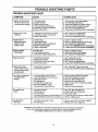
TROUBLE SHOOTING POINTS
TROUBLE
SHOOTING
SYM PTO M
CHART
CAU S E
1
CO RR ECTIO N
,,,,,,,,_,,,,
,,,
....................... ....
_,,,,._j
.....
1,
2.
3.
4.
5,
_.
Fuel tank empty,
Engine flooded,
Spark plug not firing.
Fuel not reaching carburetor,
Carburetor requires adjustment.
None of the above.
_
,,,
.....
.........
,,.
Fill tank with correct fuel mixture.
See "Starting Instructions."
Install new plug!check ignition switch.
Replace fuel filter; inspect fuel line.
See "Carburetor Adjustments."
Contact your SEARS Service Center/Dept.
Engine will not start or
will run only for a few
seconds after starting,
1,
2.
3.
4.
5.
6.
Enginewill
properly.
1. Carburetor set too fast or too slow,
2. Carburetor requires adjustment.
3. None of the above.
1'"See "Carburetor Adjustments."
2, See "Carburetor Adjustments."
3, Contact your SEARS Service Center/Dept.
Engine will not
accelerate, lacks
power, or dies
under a load,
1,
2.
3.
4.
5,
1.
2,
3.
4.
5.
Engine smokes
excessively.
1, Air filter dirty.
2. Fuel mixture incorrect,
3. (_,arburetorrequires adjustment.
......................
not idle
........,''L',
,,,,,,,,
..
Air filter dirty,
Spark plug fouled.
Carburetor requires adjustment,
Muffler outlets plugged.
None of the above.
,....................... • .•
,,,,,,, ,,,
........
,,,,
,
,,
,
Clean or replace air filter.
Clean or replace spark plug and re-gap,
See "Carburetor Adjustments."
Contact your SEARS Service Center/Dept.
Contact your SEARS Service Center/Dept,
. Clean or replace air filter.
2. Refuel with correct fuel mixture.
3. See "Carburetor Adjustments."
,,,,
,,,,,,,,,_,,,,,_,,,,,
,
Engine runs hot.
1.
2,
3,
4.
Fuel mixture incorrect.
Spark plug incorrect.
Carburetor set too high (lean),
None of the above.
1.
2.
3,
4.
Cutting head stops
under a load or does
not turn when engine
is accelerated,
1. Drive shaft not engaged.
2. Drive shaft broken,
1, See "Assembly," "Tube" insert fully.
2. Contact your SEARS Service Center/Dept.
Line does not advance
or breaks while
cutting.
1.
2.
3.
4,
5.
6.
7.
Line improperly routed in head. Line improperly wound onto spool.
Line size incorrect.
Old cutting line,
Too little line outside head.
Dirt accumulated in cover,
Line wound in wrong direction,
1,
2.
3.
4.
5.
6,
7.
Remove cover.Check line muting.
Rewind line tightly and evenly.
Use only .080" diameter line.
Replace with new cutting line,
Remove cover, Pull 4" of line to outside.
Clean co_fer.
Rewind in correct direction.
Line welds onto
spool.
1.
2.
3.
4.
5.
Line size incorrect.
Old cutting line.
Incorrect spool.
Crowding line against material being cut.
Cutting at higher speed than necessary,
1.
2,
3,
4,
5,
Use only .080" diameter line.
Replace with new cutting line.
Use proper spool,
Cut with tip of line. Reduce cutting speed.
Reduce cutting speed.
Line pulis back
into head.
1. Too little line outside of head.
2. Old cutting line,
See "Fueling Your Unit."
Replace with correct plug,
See "Carburetor Adjustments."
Contact your SEARS Service Center/Dept.
k
1. Remove cover. Pult 4"of line to outside,
2. Replace with new cutting line,
tf situations occur which are not covered in this manual, use care and good judgement.
tf you need assistance, contact your SEARS Service Center/Department or the
CUSTOMER ASSISTANCE HOTLINE at 1-800-235-5878. "
- 22 -
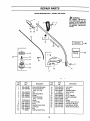
.................................... REPAIR PARTs ...............................
SEARS
WEEDWACKER
- MODEL
358.798430
WARNING
1
"All
repairs,
adjustments
and maintenance
not de..
scribed in the Operator's
Manual must be performed
by qualified
service personnel.
3
i
5
23
13 m
17
27
--9
11
1
6
Key
No.
Part
No.
1
2
530-095321
530-069496
3
4
5
6
530--015610
530-029445
530-094847
530-069666
7
8
9
10
11
12
13
STD511010
530-095249
530-016119
530-095176
530-094543
530-015820
71-85801
Key
No.
Description
Drive Shaft Housing
Assist Handle Kit
(Incl. 3, 5, 21)
Nut
Drive Shaft Grip
Clamp
Shield Kit Ass'y.
(Incl. #7 & 8)
Screw
Line Limiter
Knob
Flexible Drive Shaft
Dust Cup
Bolt
Cutting Head Ass'y.
14
16
17
18
19
21
24
25
26
27
29
23
Part
No.
530-094878
530-094830 •
530-094827
71-85811
530-094828
530-069252
952-03013_9
530-015768
530-015774
530-047329
53O-O83546
530-031159
53O-047467
Description
Hub Ass'y.
Spring
Release Button
Spool w/Line
Cover
Kit-T-Handle
Shaft Lubrication
Nut
Screw
Throttle Lever Ass'y.
Operator's Manual
Hex Wrench (5/32)
Shaft Warning Decal
""
17
2O
/18
46
53
54
55
57
60
65
61
66
62
63
:
e_67
73
._i_:
.
-_/_
58----J
Enginei
,r,
Cart).
Repair
Kit
\
74
- 24 -
Gasket !
Kit
I
\
71
! Spark---i
Arrestor I
72
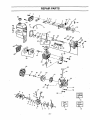
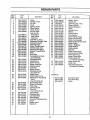
REPAIR PARTS
Key
No.
1
2
3
4
5
6
7
8
9
i
Pa_
No.
530--015773
530--027529
530-027530
530-015849
530-015852
530-015254
530-O38915
530-037930
10
11
12
13
14
15
16
17
18
19
2O
530-069571
530--069216
530--069247
530-014362
530-069648
t 530-019156
530-014347
530-015775
530-037498
53O-O47320
t 530-019154
530-027593
530-027594
530-010960
21
22
23
24
25
26
27
28
530--010945
530-015126
530-015772
530-015780
530--027546
530-027547
530-015771
530-014016
29
3O
32
530-027545
530-047319
530-0140O4
33
34
35
36
37
39
4O
41
42
43
44
45
46
530-016O64
530-015162
530-025875
t 53O-019178
530--069275
530-032103
530-015787
530-019158
530-032102
530-015789
530-015717
530-038945
530-069257
Description
Screw
Air Filter Cover
Air Filter
Screw
Spacer-Choke
Wave Washer
Choke Shutter
Air Filter Plate
Fue! Line Kits
Palmer/Tank
CarbJPrimer
TanldCarb.
Fuel Pick-up Ass'y.
Carburetor w/Limiter Caps
Carburetor Gasket
Fuel Cap Ass'y.
Screw-ThrotUe Cable
Throttle Cable Ass'y.
Shroud & Tank Ass'y.
Gasket--C'caselShmud
Reed
Reed Stop
Connecting Rod Ass'y,
(Incl. Bearings)
Crankshaft Ass'y.
Rywheel Key
Screw-Shroud
Screw--Lead Wire
Switch Insulator
Lead Wire
Screw-Shroud
Crankcase Ass'y.
(Incl. #39-42)
Switch Ramp
Switch Spring Ass'y.
Crankcase & Crankshaft
Ass'y.
(Incl. #21,28 & 43)
Screw-Reed Valve
Piston Pin Retainer
Piston Ring
Cylinder Gasket
Piston Kit
(Incl. #34,35 & pin)
inner Bearing
Retaining Ring
Crankshaft Seal
Outer Bearing
Crankshaft Retaining Ring
Screw
Muffler Guard
Muffler Kit
Part
Description
No..................................................................
,,
,,,,
Key
No.
47
48
49
5O
51
52
53
54
55
56
57
58
59
60
61
62
63
64
65
66
67
69
7O
71
5,30--036409
530-069626
Champion
530--015239
530-039134
530-015128
530-047198
530-015828
530--027953
530--038959
530-016080
530-015770
530-015769
530-069291
530-029395
530-015496
530-027523
530-027569
530-069232
530-015767
530-015768
530-038874
530-016091
530-069276
72
73
74
952-7016 ! 2
530-038404
530-069623
Muffler Spring
Cylinder Kit
Spark Plug (RCJ-_Y)
Screw-Cylinder
Ignition Module Kit
Screw
Flywheel Ass'y.
Washer
Drive Coupling
Fan Housing
Screw-Starter Pulley
Screw-Fan Housing
Screw-Fan Housing
Starter Pulley Kit (incl. #57)
Starter Spring
Screw - Retaining
Pulley Retainer
Starter Handle
Rope Kit
Screw-Pinch Clamp
Locknut-Pinch Clamp
Primer Bulb Ass'y.
Screw-Primer Bulb
Engine Gasket Kit
( t Indicates Contents)
Spark Arrestor Kit
Limiter Cap
Carburetor Repair Kit
( • Indicates Contents)
Not Shown
530-047475
530-0473_4
530-085271
- 25 -
Instruction Decal
Ass'y PartsBag
Carton
NOTES
.................
_,,,_,_
,,
,,, i
llllll
.....................................................
_-
- 26 -
.....
i
iL lllll
ii i
CRAFT514AII®
Operator's
Manual
32 cc/2.0 cu. in. 2-CYCLE ENGINE
17 Inch Semi-Automatic Head ®
GAS WEEDWACKER ®
Model No.
358.798430
Each Gas Weedwacker° has its own model number.The model
number for your unit will be found on a decal attached to the
unit.
IFYOU NEED REPAIR
SERVICE OR PARTS:
REPAIR SERVICE
1-800-4-REPAIR
(1-800-473-7247)
All parts listed herein may be ordered from any Sears,
Roebuck and Co, Service Center and most Retail Stores.
WHEN ORDERING REPAIR, ALWAYS GIVE THE FOLLOWING INFORMATION AS SHOWN IN THIS LIST:
• PRODUCT-'GAS
ORDERING PARTS
1-800-FON-PART
(1-800-366-7278)
- MODEL NUMBER - 358.798430
• PART NLJMBER
-
PART DESCRIPTION
Your Sears Merchandise has'-added value when you consider
that Sears has service units nationwide staffed with Sears
trained technicians.., professional technicians specifically
trained on Sears products, having the parts, tools and equipment to insure that we meet our pledge to you, we service what
we seII.
CUSTOMER
ASSISTANCE
Sears,
WEEDWACKER"
Roebuck
and Co., Hoffman
Estates,
IL 60179
U.S.A.