1
Chapter
General Information
1-1
Chapter 1
General Information
This chapter provides information and a general overview of the iiLINX
Solid Inkjet 100 Printer. Theory of operation, printer specifications and
components are presented in the following sections:
1-2
ii LINX™ Solid Inkjet 100 Service Manual
General Information
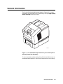
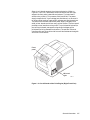
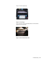
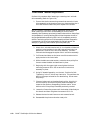
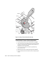
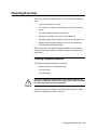
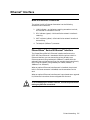
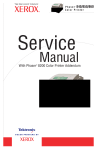
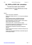
The iiLINX Solid Inkjet 100 printer, shown in Figure 1-1, is a userinstallable, low maintenance, environmentally friendly, High Quality
Referral Image PostScript printer.
0388-01
Figure 1-1. The iiLINX Solid Inkjet 100 Printer (shown with optional
Auxiliary Feeder Unit Assembly)
To ensure complete understanding of the Solid Inkjet 100 printer, we
recommend participation in Solid Inkjet 100 printer service training.
General Information
1-3
Solid Inkjet 100 Printer Overview
The Solid Inkjet 100 Printer is an Adobe PostScript Level 3 (Version
3010) grayscale, solid inkjet printer. It supports 409 x 409 dots-perinch (dpi) resolution at draft mode, and 600 x 600 dpi at High
Resolution Medical mode. The speed of producing images is 4.8 pagesper-minute (ppm) in draft mode, and 2.5 ppm in High Resolution
Medical mode.
Base Solid Inkjet 100 printer
The base Solid Inkjet 100 printer features 136 built-in fonts, and is
equipped with 64 Mbytes of RAM. It can be upgraded to 128 Mbytes
of RAM by adding an optional 64 Mbyte RAM DIMM.
All printers support two available paper trays: A and A4 trays and an
optional 500-sheet high-capacity paper tray assembly give the printer
a two-tray capability. The high-capacity paper tray assembly is
usually referred to as an auxiliary feeder unit.
A 133-MHz PowerPC processor oversees print engine operations and
PostScript image processing. The printer features an integral
bidirectional parallel port (IEEE 1284C with ECP mode) and a
10baseT Ethernet port (with support for EtherTalk, TCP/IP, DHCP
and Windows Peer-to-Peer). A USB high-speed serial port is also
provided.
An optional Ethernet interface board offers a 10BaseT/100BaseT/
10Base2 Ethernet connection providing standard protocol support for
EtherTalk, TCP/IP and DHCP. When installed, this card disables the
standard 10baseT port.
A second rear panel slot accommodates an internal IDE hard drive for
DICOM support.
Solid inks
Solid inks, sometimes called phase-change inks, are solid at room
temperature and are liquid at the higher temperature used during
printing. The inks solidify almost instantly after being jetted onto the
printer’s drum. Each of the Solid Inkjet 100 printer inks is especially
formulated for this printer; the inks are not interchangeable with
other models of solid ink printers.
NOTE: Turning the printer off and allowing it to cool causes it to
perform a printhead cleaning and purge cycle upon power-up. The
printer’s purge cycle consumes a significant amount of ink. During
normal use and servicing, turn the printer off and allow it to cool only
when necessary.
1-4
ii LINX™ Solid Inkjet 100 Service Manual
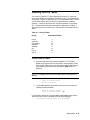
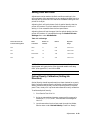
Memory Considerations
The printer dual frame buffer allows for printing one image while
processing a second image (which gives greater printing throughput).
With additional RAM memory, the printer’s capabilities increase as
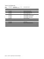
detailed in Table 1-1:
Table 1-1. Installed RAM and Printer Capabilities
Feature
Base
(64 Mbytes)
Additional RAM Upgrade
(128 Mbytes)
Fast (draft) printing
yes
yes
High-Resolution
Medical Printing
yes
yes
Pipelining
yes
yes
DICOM Support
no
yes
To verify what type of RAM is installed, print the 2-page
Configuration Page from the Front Panel menu and refer to “Installed
RAM.”
For example:
Installed RAM:
64 Mbytes
Memory Slot 1:
SDRAM/Non-parity/32 Mbytes/
KMMe 665 403 CTL-GO
Memory Slot 2:
SDRAM/Non-parity/32 Mbytes/
16LSDT 464AG-662C1
General Information
1-5
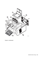
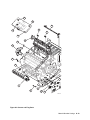
Print Engine Assemblies
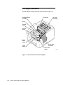
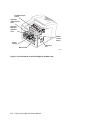
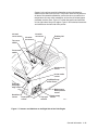
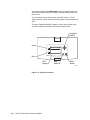
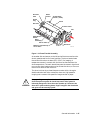
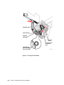
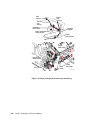
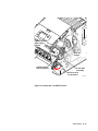
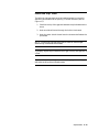
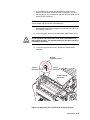
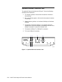
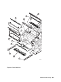
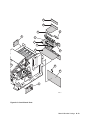
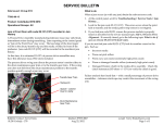
Internal features of the print engine are illustrated in Figure 1-2.
Cap/Wipe/Purge
assembly
Ink load
assembly
Printhead
Drum
Transfix
roller
Process
motor
Paper/
Drum
heater
Y-axis
motor
X-axis drive
and motor
Paper feed
motor
Figure 1-2. Internal Features of the Print Engine
1-6
ii LINX™ Solid Inkjet 100 Service Manual
0388-02
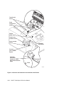
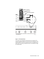
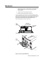
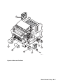
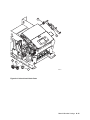
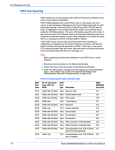
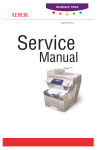
Seven circuit boards support the printer’s electronics. (Refer to
Figures 1-3 and 1-4). Two boards, called I/O boards, left and right,
support the front panel, solenoids and sensors. The main board
contains the printer’s CPU processor, RAM and ROM. The power
supply accepts the AC input voltage and distributes it or converts it
to various other levels of required DC voltages and distributes them.
The power control board distributes power supply voltages to the
other printer boards and drives many printer motors. The front panel
provides a user interface to the printer. The printhead drive board, a
part of the printhead, manages the signals and voltages of the
printhead’s printing elements and sensors. The optional Ethernet
interface card and internal hard drive could be considered the eighth
and ninth circuit boards.
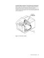
Front
panel
I/O board
right
0388-03
Figure 1-3. Circuit Boards of the Print Engine (Right Front View)
General Information
1-7
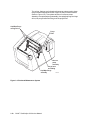
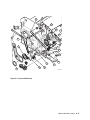
Printhead drive
board
Optional
Internal hard
drive
Optional
Ethernet
Interface
card
Power
control
board
Power
supply
Main board
I/O board
left
0388-04
Figure 1-4. Circuit Boards of the Print Engine (Left Rear View)
1-8
ii LINX™ Solid Inkjet 100 Service Manual
An internal data bus, called the I2C bus, connects all I/O boards to the
main board. (Refer to Figure 1-5.) Through this single bus, the main
board can “poll” the I/O boards for the state of the printer’s sensors as
well as actuate the printer’s solenoids. This data bus greatly
simplifies the wiring that would otherwise be required for monitoring
numerous sensors and solenoids. The I2C bus also extends down to the
Auxiliary Feeder Unit.
Auxiliary
feeder unit
connection
I2C bus
0388-05
Figure 1-5. The Printer’s I2C Bus
General Information
1-9
The printer features a printhead maintenance system used to clean
the printhead faceplate and clear clogs from the printhead nozzles.
(Refer to Figure 1-6.) The system consists of a vacuum pump
assembly, the cap/wipe/purge assembly, the cap/wipe/purge carriage
drive, the purge hose and tubing, and the purge filter.
Cap/Wipe/Purge
carriage drive
Purge
Filter
Vacuum
pump
assembly
Purge hose
and tubing
Cap/Wipe/Purge
assembly
Figure 1-6. Printhead Maintenance System
1-10 ii LINX™ Solid Inkjet 100 Service Manual
0388-06
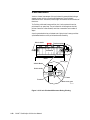
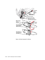
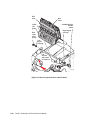
Sensors in the printer provide information to the main board to
determine the state of the printer. The printer monitors the positions
of some of the movable assemblies, such as the drum, as well as the
temperature of many other assemblies, such as the printhead, paper
preheater and the drum. Figure 1-7 shows the sensors and switches
on the right side of the print engine. Figure 1-8 illustrates the sensors
and switches on the left side of the printer.
Ink-stickout sensor
Ink load
cover sensor
Top cover
switch
Exit/tray-full
sensor
Ink-sticklow sensor
Front cover
switch
A4-size media
sensor
A-size media
sensor
Cap/Wipe/Purge
home sensor
Preheater
entry/right
edge sensor
Maintenance
blade position
sensor
Hand-feed
sensor
Paper-pick
sensor
Tray type
sensors
Paper-empty
sensor
0388-07
Figure 1-7. Sensors and Switches on the Right Side of the Print Engine
General Information
1-11
Transfix exit
sensor
Drum
temperature
sensor
Duplex
paper sensor
Drum-homeposition sensor
Drum encoder
sensor
Preheater
exit sensor
Process
gear position
sensor
Transfix
roller
Preheater
exit sensor
located on inside
wall of drum/transfix
frame
Preheater
Drum
0388-34
Figure 1-8. Sensors and Switches on the Left Side of the Printer
1-12 ii LINX™ Solid Inkjet 100 Service Manual
CAUTION
The actual position of some printer assemblies, such as the
printhead or the cap/wipe/purge assembly, cannot be ascertained at
all times. The printer records, in NVRAM, where it last positioned
such assemblies each time it moves them. If, after power-down or a
power interruption, the assemblies are manually repositioned, the
printer erroneously assumes that the assemblies are in the position
it last left them. This assumption can result in damage to the printer
when it tries to position the assemblies. For example, the printhead
could be tilted forward and crash into the raised cap/wipe/purge
assembly.
Before turning on the printer, ensure the printhead is tilted forward,
centered in front of the drum and the cap/wipe/purge assembly is in
the retracted, home position. The tilt cam gear should be
disengaged from the gear drive train.
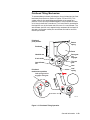
Electric clutches and solenoids are used by the printer to engage
rollers as needed to move paper through the printer as well as start
some print processes. Refer to Figure 1-9.
Drum maintenance
cam clutch
Cap/Wipe/Purge
clutch
Upper feed
roller clutch
Air valve
solenoid
Pick
clutch
Transfix
solenoid
0388-08
Figure 1-9. Solenoids and Clutches on the Print Engine
General Information
1-13
The Main Board
The main board features the printer’s PowerPC processor that
controls the engine and the PostScript processing. Refer to Figure 110. Prominent on the main board is the code ROM DIMM and the
RAM DIMM plug-in modules. The code ROM DIMM also contains the
printer’s on-board fonts. Variations of the code ROM DIMM contain
alternate language fonts such as Kanji or Hangul.
Network connection is provided through a built-in 10baseT port.
The printer stores unique printer status and PostScript values in its
NVRAM module. The printer’s Ethernet address, unique to each
printer, is stored in Boot ROM/Printer ID chip, an 8-pin socketed IC
in location U390. All these socketed components should be transferred
to a replacement main board to maintain customer-unique settings.
Boot ROM/
Printer ID
RAM DIMMs
NV RAM/
Real Time Clock
Code ROM
DIMM
0388-09
Figure 1-10. Features of the Main Board
1-14 ii LINX™ Solid Inkjet 100 Service Manual
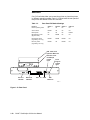
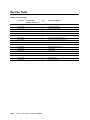
Media Tray Type Sensing
The combinations of the three tray sensors inform the print engine
what type of media tray (A or A4) is installed. These combinations are
shown in Table 1-2. The print engine does not detect the type of media
installed in the tray; it only detects the particular tray being used by
the presence of sensor flags on the side of the tray. The tray sensors
are located on the right-side interior of the paper tray slot, mounted
on I/O board right. There are two tray types:
•
Letter (A-size). This tray is sized for 8.5 x 11-inch (U.S.)
paper.
•
Metric Letter (A4-size). This tray is used for 210 x 297 mm
(Metric) paper.
Table 1-2.
Tray Switch Sensor Combinations
Top switch
Tray type
A Paper
Closed
A4 Paper
Open
Middle switch
Open
Closed
Bottom switch
Open
Open
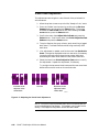
Front Panel
These front panel features (shown in Figure 1-11) are found on the
printer:
•
128 x 64 pixel backlit LCD graphic display
•
Two push buttons and four navigation arrow buttons
•
Two LEDs (Power and Error)
LCD. The backlit LCD serves two purposes: displaying current image
processor and print engine status information and displaying an
interactive menu. Status information includes image processor status
such as Ready to Print, Receiving Data and Printing. Print engine
status includes messages such as Out of Paper, Paper Jam and Add
Ink as well as error messages.
Customers can review and modify certain NVRAM, I/O ports and
peripheral parameters. Using the front panel to review and change
parameters is discussed in the topic, “Adjustments”.
Buttons. Four of the six buttons are arranged as a diamond-shaped
keypad. The other two buttons are used as Select and Help.
In the Service Support menu, pressing and holding the Left arrow
button , and then pressing the Select button enters the hidden
service support menu.
Pressing and holding the Right arrow button and then pressing the
Select button proceeds immediately to the language selection menu.
General Information
1-15
Pressing and holding the Left arrow while turning off the printer
will confirm the printhead is correctly parked by flashing both front
panel LEDs.
Turning the printer on with the rear panel DIP switch 2 in the
“down” position, allows access to the front panel during the warm-up
cycle.
The topic “Resetting NVRAM” explains how to use the front panel
buttons to reset the NVRAM to its factory-default values.
Navigation
buttons
Power
READY TO PRINT
Error
LCD
Display
Help
button
Select
button
0388-10
Figure 1-11. Printer Front Panel
1-16 ii LINX™ Solid Inkjet 100 Service Manual
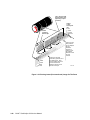
Rear Panel
Connectors
The rear panel (Figure 1-12) of the printer features the host interface
connectors to the printer; it includes the following connectors:
•
Standard parallel (high-density connector), IEEE 1284C
•
Twisted Pair (10BaseT) Ethernet connector
•
Universal Serial Bus port
•
A special 5-pin connector accommodates a service RS-232 cable
from a PC running PC-based diagnostics.
The rear panel also includes two option slots. With the addition of an
optional Ethernet Interface network card in the lower slot, the printer
can support 10Base2 or 100BaseT Ethernet connectors.
NOTE: When an optional Ethernet Interface card is installed, the
printer’s built-in 10BaseT Ethernet port is disabled.
The second slot accommodates an internal IDE hard drive for print
DICOM support.
Health LEDs
Two health LEDs indicate the status of the printer’s CPU functions:
PostScript (PS) processing and Print Engine (PE) control.
•
Blinking: The printer is operating normally. Both LEDs blink
irregularly during diagnostics. To indicate the printer passes
the POST tests and is operating normally, the left (PS) LED
flashes in a “heartbeat” rhythm (on 0.5 seconds, off 0.5
seconds). The right (PE) LED pattern is two quick flashes on,
then off for a count of two for a total cycle time of just over two
seconds.
If a soft error occurs, image processing occurs, but in a reduced
capacity. Soft errors include failure of expansion memory
DIMMs or of any of the interface ports. When a soft error
occurs, the printer automatically prints a startup page listing
the error.
•
On or Off, or blinking a coded error indication: A hard error
condition has occurred that would keep the image processor
board from operating. Refer to the topic “Error Codes and
Messages” for the meaning of a coded indication.
General Information
1-17
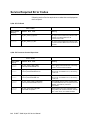
Switches
Four DIP switches allow you to reset the printer or place the printer
in different operating modes. Figure 1-12 illustrates the rear panel of
the printer and location of the DIP switches.
Table 1-3.
Rear Panel DIP Switch Settings
Function
Normal operating mode
Switch 1
UP
Switch 2
UP
Switch 3
UP
Switch 4
UP
Service mode
DOWN
UP
UP
UP
Reset printer
UP
UP
UP
DOWN
Manufacturing mode
(Bypass mode)
UP
DOWN
UP
UP
Development mode
(engineering use only)
DOWN
DOWN
DOWN
UP
Recovery mode
(engineering use only)
DOWN
UP
DOWN
UP
IDE hard drive
Optional Ethernet
Interface card
PostScript
health
light
Ethernet Card
TX
RX
Service
RS-232
100
Mbs
TP
LINK
10/100Base-TX
10Base2
Ethernet
10BaseT
Parallel
USB
Print
Engine
health
light
DIP
switches
0388-11
Figure 1-12. Rear Panel
1-18 ii LINX™ Solid Inkjet 100 Service Manual
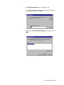
Bypass Mode (Manufacturing Mode)
Bypass mode allows you to access the front panel menus (bypassing
the engine and PostScript initializing processes) without having to
wait for the printhead to warm up. This way, you can observe or
change some of the printer settings without waiting for the printer to
complete the normal warm up sequence. Meanwhile, the printer
continues to warm-up and initialize “in the background.”
1. At the rear of the printer, set DIP Switch 2 in the down
position. Ensure Switches 1, 3 and 4 are up. (Normal
operation is all switches up.)
2. Turn on the printer.
The printer will not print a Cleaning Page or a Startup Page when
placed in Bypass Mode.
Cool Down Mode
The printer features a menu item that accelerates the cooling down of
the printhead. When the printer is turned off, it automatically gives
the option of performing a quick cool down.
1. Turn off the printer.
2. Scroll to the menu item Quick Cool to Move and press the
Select button.
3. Open printer doors to help speed the cooling process.
The printer turns off all the engine heaters and runs the fans on high
until the ink in the printhead has solidified. Then the printer shuts
itself off.
General Information
1-19
Preparation for Moving the Solid Inkjet 100 Printer and
Accessories
It is very important that you follow the correct repacking procedure
before shipping the Solid Inkjet 100 printer. Complete repacking is
required. Failure to properly repack the printer can damage the
printer’s internal components. You are responsible for any shipping
damage to the printer that results from improper or inadequate
packing.
Repacking for shipment consists of four basic tasks. Each of these
tasks is explained in detail. If you have questions regarding any of
the repacking procedures, call Sterling for assistance:
Sterling Diagnostic Imaging, Customer Care Center at (800) 2529099. Outside the U.S. and Canada, contact your local Sterling
Diagnostic Imaging service organization.
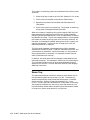
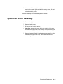
Overview
After reviewing this section, follow the more detailed processes which
follow to complete this task.
1. Turn off the printer using the On/Off switch and then selecting
Shut Down For Moving Printer at the front panel.
2. Remove the maintenance drawer, seal it in a plastic bag, and
store the tray on a flat surface.
NOTE: A used maintenance drawer leaks drum fluid if tipped.
3. Make sure that the printer has completed its shut down before
moving the printer (after approximately 15 minutes, the front
panel goes blank). This allows the ink to solidify.
4. Repack the printer and its accessories using the original
packing materials.
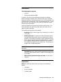
Turning off the Printer
CAUTION
To avoid damaging the printer’s internal components, always turn
the printer power off using the On/Off switch (this places the
printhead in the proper position for safe shipment). Failure to do so
may result in damage to the printer. Never turn off the printer by
pulling the power cord.
1-20 ii LINX™ Solid Inkjet 100 Service Manual
1. Use the rear-panel On/Off switch to turn off the printer.
2. At the front panel, immediately select Quick Cool to Move
Printer (you have 4 seconds before the display goes blank).
The printer reports the shut down status and takes approximately 15
minutes to cool down. While it is cooling, it is recommended that you
remove the maintenance drawer (see the next topic).
If you do not select Quick Cool to Move Printer, you must wait 30
minutes for the ink to solidify. Before moving the printer, always
wait for the ink to solidify or you may damage the printer.
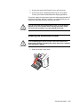
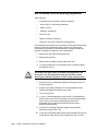
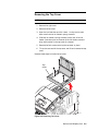
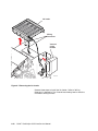
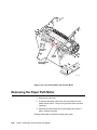
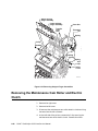
CAUTION
Removing the Maintenance Drawer
To avoid damaging the printer, always remove the maintenance
drawer before moving or shipping the printer. Never ship a partially
used maintenance drawer.
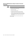
CAUTION
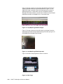
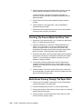
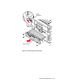
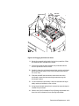
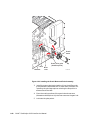
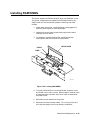
1. Open the printer’s front cover.
1239-58
General Information
1-21
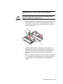
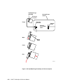
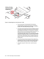
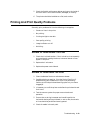
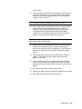
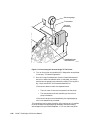
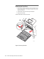
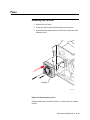
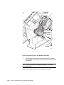
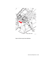
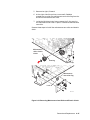
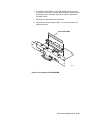
2. Remove the maintenance drawer from the printer. Once you’ve
removed the maintenance drawer, keep it level.
1239-59
WARNING
A used maintenance drawer leaks drum fluid if tipped. Keep the
maintenance drawer level to prevent spills. Contact with
maintenance drawer fluid poses no health risk, however, do not
leave the used maintenance tray where it could spill and create a
slipping hazard.
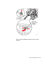
3. Place the used maintenance drawer in a plastic bag and seal
the bag. Store the used maintenance drawer for future use. Do
not ship a partially used maintenance drawer.
Disconnecting the Cables
Once the printer completes its shut down process, the front panel goes
blank. Once this happens, disconnect the power cord and all other
cables from the printer.
1-22 ii LINX™ Solid Inkjet 100 Service Manual
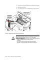
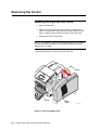
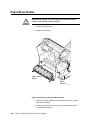
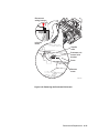
Repacking the Printer and its Accessories
The printer weighs about 36 kg (79 lb.). Do not attempt to lift it
without the assistance of another person.
WARNING
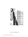
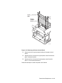
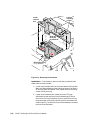
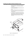
1. Repack the media tray. Remove the media trays and remove all
media from the trays. Position the cardboard tray insert into
the media tray to prepare it for shipping. Reinsert the media
tray into the printer.
1239-38b
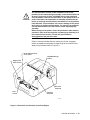
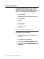
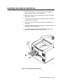
2. Repack the printer. Position the lower cushion insert in the
shipping tray as shown in the illustration. Lower the printer
onto the cushion inserts. Place the plastic bag provided over
the printer. Place the cushion inserts on each side of the
printer.
3. Repack the printer’s accessories. Place the power cord, cleaning
kit, and all printer documentation in the area provided in the
accessories box. Do not ship a partially used maintenance
drawer.
General Information
1-23
1239-35b
Figure 1-13. Repacking the Printer
1-24 ii LINX™ Solid Inkjet 100 Service Manual
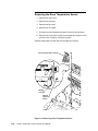
WARNING
The printer is not permanently attached to the Auxiliary Feeder unit.
When moving the printer or auxiliary feeder unit, move each unit
separately to avoid damage or personal injury. The printer weighs
about 36 kg (79 lb.). Do not attempt to lift it without the assistance
of another person.
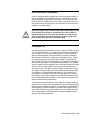
Repacking the Auxiliary Feeder Unit
If you have an Auxiliary Feeder unit, repack for shipment using the
original packaging.
Remove the media tray from the Auxiliary Feeder unit and remove all
media from the tray. Slide the media tray into the Auxiliary Feeder
unit and place the assembly inside the plastic shipping bag. Place the
front and rear cushions on the Auxiliary Feeder unit. Place the entire
assembly into the cardboard box.
1239-01
General Information
1-25
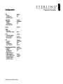
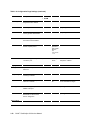
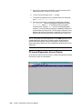
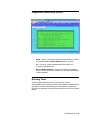
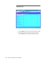
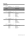
Configuration Page
The configuration page, shown on pages 1-27 and 1-28, lists the
values the printer stores in its NVRAM. These values can be
informative when troubleshooting the printer, particularly networked
operations. The configuration page gives information such as:
•
General information about the printer, such as page count, the
programmed name, Ethernet address, time-outs, number of
fonts and total memory
•
Printhead information such as serial number, calibration and
adjust values
•
Parallel port settings
•
USB setting
•
Hard drive
•
Network information
•
EtherTalk settings
•
Novell NetWare settings
•
TCP/IP settings
Configuration page settings are provided in Table 1-4.
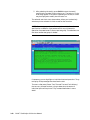
Printing the Configuration Page
1. Turn on the printer.
2. Allow the printer to complete its power-up self-tests. The front
panel displays:
READY TO PRINT
3. Scroll to Menu and press the Select button.
4. Scroll to the menu item Demo and Test Pages and press the
Select button.
5. Scroll to the menu item Print Configuration Page and press
the Select button.
1-26 ii LINX™ Solid Inkjet 100 Service Manual
General Information
1-27
1-28 ii LINX™ Solid Inkjet 100 Service Manual
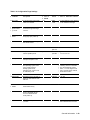
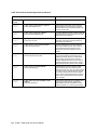
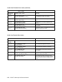
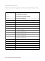
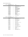
Table 1-4. Configuration Page Settings
Parameter
Description
Saved in
Default
Limits or alternate choices
Any name defined by the customer
up to 32 characters in length.
NVRAM
Printer name
The current name of the printer
as seen on a network
yes
Ii LINX
SIJ100
Page count;
upper and lower
tray counts
Total number of print jobs
processed through the image
processor.
yes
0
Startup page
enabled
Indicates if the printer prints a
startup page upon power-up.
yes
Yes
Serial number
Unique number representing the
printer serial number
yes
Ii LINX Solid
Inkjet 100
Product
Printer ID
No
A unique number for each
Ethernet-capable printer.
yes
Hardwaredependent.
PostScript version Firmware level of the
PostScript interpreter code.
N/A
3016.106
Firmware version
N/A
Firmware levels of the main
board operating system code
version, printer engine’s
operating system code,
PostScript code, engine code,
and networking code.
Flash Installed
Legal values have the form
xx:xx:xx:xx:xx:xx
a.aa/b.bb/c.cc/d.dd, where a.aa is
the Sterling version of VxWorks,
b.bb is the PostScript version
number, c.cc is the engine code
version, and d.dd is the network
code firmware version
Yes
Installed RAM
Total amount, type, and size of
RAM on the main board in each
DIMM slot.
64 Mbytes
64, 96,128
ROM fonts
available
Number of fonts stored in the
printers ROM memory.
136
Sys/Job Start
Indicates if the printer is to
execute a Sys/Start job file
found on an attached hard
drive at power-up
yes
yes
no
Job Timeout
Amount of time a job can take
to process.
yes
0 seconds
Any value denoted in seconds. 0
means unlimited amount of time
General Information
1-29
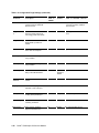
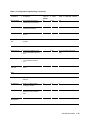
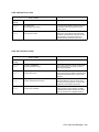
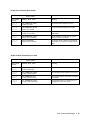
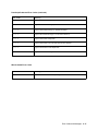
Table 1-4. Configuration Page Settings (continued)
Parameter
Description
Saved in
Default
Limits or alternate choices
NVRAM
Wait Timeout
Amount of time the image
processor waits for additional
data from a host.
yes
40 seconds Any value greater than 14 denoted
in seconds; 0 means unlimited
amount of time
Energy Star time- Amount of idle time allowed
out
before the printer switches to
a low energy power down mode.
yes
67 hours
Any integer from 1 to 999 denoting
hours.
Intelligent Ready
Indicates if the automatic
standby/wake up feature is
enabled.
yes
on
off
Media Source
Indicates the default tray the
printer uses for self-prints
yes
Upper Tray
Upper Tray, Lower Tray
Upper Tray
Indicates the size and type
of tray installed
no
Letter, A4
Lower Tray
Indicates the size and type
of tray installed
no
Letter, A4
Print Quality
Indicates the combined
setting of the HW Resolution.
yes
High
Resolution
Medical
High Resolution Medical, Draft
Parallel Port
Enabled
Indicates if the parallel port is
enabled
yes
Enabled
Disabled
Language
Indicates the language
interpreter in use at the port
yes
PostScript
Encoding
Indicates the type of data
encoding at the parallel port
yes
Binary
ACSII (normal), Raw, TBCP
Job pipelining
Indicates if multiple printfile
processing is allowed
yes
Off
0n
Output Device
Device used for standard
output and standard error
yes
Parallel
any communication device
1-30 ii LINX™ Solid Inkjet 100 Service Manual
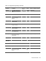
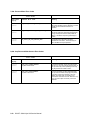
Table 1-4. Configuration Page Settings (continued)
Parameter
Description
Saved in
Default
Limits or alternate choices
NVRAM
Handshake
Setting whether unidirectional
or bidirectional communication
is used.
yes
Bi-directional Uni-directional
Language
Indicates the language
interpreter in use at the
parallel port
yes
PostScript
Encoding
Indicates the type of data
encoding at the port
yes
Binary
ACSII (normal), TBCP
Job Pipelining
Indicates if multiple printfile
processing is allowed
yes
Off
On
IDE Disk
Indicates if the internal
hard drive is installed
no
Size
Indicates the physical size
of the installed IDE drive
no
Boot Delay
Number of seconds the
printer waits before booting
up the hard drive.
yes
USB
Disk size in Gbytes
0
Any positive integer
Polling
Network
Information
Version
Integer 1 to 255
Time
<day><date><time><year>
Time Source
Source of the time set in printer,
such as a remote computer
dialog box
Set at
factory
Clock not set
General Information
1-31
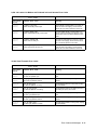
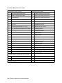
Table 1-4. Configuration Page Settings (continued)
Parameter
Description
Saved in
Default
Limits or alternate choices
NVRAM
Last Config Time
Last date the printer’s
configurations were altered
yes
SysAdmin contact Name of system administrator
yes
Empty string
Printer Location
Physical location of printer
as set by system administrator
yes
Empty string
PhaserShare
Indicates the type of Phaser
Share network card installed
no
Built-in
Network Address
A unique number for each
Ethernet-capable printer.
yes
Hardwaredependent.
Legal values
have the
form
xx:xx:xx:xx:
xx: xx
EtherTalk
Indicates the type of interpreter
in use at the port.
yes
PostScript
Level 2
Language
Ethernet
Not installed, Disabled,
<interpreter> enabled
PostScript
Filtering
Interpretation of special
characters
yes
None
Job Pipelining
Indicates if multiple printfile
processing is allowed
yes
Off
On
Name
The current name of the printer
as seen on a network
yes
Ii LINX SIJ
100
Any name defined by the customer
up to 32 characters in length.
Printer type
Indicates the type of printer
installed at the port.
Zone
Name assigned by network
administrator for the zone the
printer is assigned to.
Network Node
1-32 ii LINX™ Solid Inkjet 100 Service Manual
LaserWriter Any string, 32 character or less
yes
Any string, 32 characters or less
Table 1-4. Configuration Page Settings (continued)
Parameter
Description
Saved in
Default
Limits or alternate choices
NVRAM
IPX
Indicates which IPX frame types
the printer accepts
IPX Networks
Ethernet 802.2
yes
Enabled
Disabled
Ethernet 802.3
yes
Enabled
Disabled
Ethernet II
yes
Enabled
Disabled
Ethernet SNAP
yes
Enabled
Disabled
NetWare port
interpreter
Language
Indicates the type of
interpreters in use at the port.
yes
PostScript
Disabled, <interpreter>
Filtering
Interpretation of special
characters
yes
None
Interpreter-based
Job pipelining
Indicates if multiple printfile
processing is allowed
yes
On
Off
Operating Mode
Print Server Name Name of printer server.
Print server
yes
Connection Mode 1 - Directory Services,
yes
2 - Bindery
3 - Directory and Bindery Services
Preferred DS Tree Directory Services Tree where
printer initially connects
yes
TEK01B009, user-defined
hardware
dependant
2 - Bindery 1 - Directory Services, 3 - Directory
and Bindery Services
Max length 48 bytes
General Information
1-33
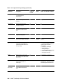
Table 1-4. Configuration Page Settings (continued)
Parameter
Description
Saved in
Default
Limits or alternate choices
Set, Not set
NVRAM
Login Password
Indicates whether or not a
network password has been set.
yes
Not set
Enable Banners
Print banner
yes
No
Config Retry
Interval
Time in seconds to wait before
retrying to configure
yes
60 seconds
Queue Scan
Interval
Rate at which printer will scan
queue for print jobs.
yes
15 seconds An integer 1 through 300 in
seconds
Status Message
TCP/IP port
interpreter
Indicates the type of interpreter in yes
use at the port.
Not authorized, Disabled
Host Name
IP Address
The Internet Protocol address.
If null, the address will be set
at run time via RARP or BOOTP.
yes
Not Set
String of 15 or fewer characters of
the format N.N.N.N followed by the
word “Dynamic” if IP Address
Dynamic parameter is set to true.
Network Mask
Indicates which fields of the
IP Address designate the
network portion and which
designate the node portion.
If null, the mask will be
determined from the printer’s
IP address or the BOOTP or
ICMP Netmask Reply.
yes
Default
String of 15 or fewer characters of
the format N.N.N.N
Router/ Gateway
A list of addresses of the
gateways to other networks.
yes
None
String of 15 or fewer characters of
the format N.N.N.N
Frame
Data packet encapsulation
type for ARP/ RARP requests
and IP datagrams.
yes
DIX
Adaptive, 802.2-SNAP. May be
followed by the word “Dynamic”
RARP
Reverse Address Resolution
Protocol/ Boot Parameter
Protocol. Used for setting the
printer’s IP address from a boot
server.
yes
False
True
1-34 ii LINX™ Solid Inkjet 100 Service Manual
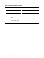
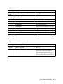
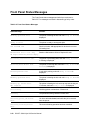
Table 1-4. Configuration Page Settings (continued)
Parameter
Description
Saved in
Default
Limits or alternate choices
False
True
NVRAM
BOOTP/ DHCP
Used for setting the printer’s
IP address from a boot server
yes
IP Address Source Indicates from what source the
IP address was obtained
yes
SMTP Server
Host that email notification will
deal with
yes
Empty field 16 characters
SMTP Reverse
Path
Destination of email error
messages
yes
Empty field 80 characters
DNS
Primary Server
Provides the IP address of the
primary Domain Name Services
server
None
This is overridden by BOOTP/
DHCP
Secondary Server Addition source of IP address
for a Domain Name Services
server
None
Search Domain
Names(s)
None
256 characters
Local domain name of DNS
resolver
LPR
Filtering
Interpretation of special
characters
yes
None
Interpreter-based
Job pipelining
Indicates if multiple printfile
processing is allowed
yes
yes
no
Host Access List
List of TCP/IP network
addresses for host access to
printer
yes
Unrestricted
AppSocket port
interpreter
General Information
1-35
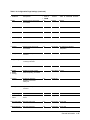
Table 1-4. Configuration Page Settings (continued)
Parameter
Description
Saved in
Default
Limits or alternate choices
NVRAM
Language
Indicates the type of interpreter
in use at the System V
configured port.
yes
PostScript
Filtering
Interpretation of special
characters
yes
None
Interpreter-based
Job pipelining
Indicates if multiple printfile
processing is allowed
yes
On
Off
Host Access List
List of TCP/IP network
addresses for host access to
printer
yes
Unrestricted
Syslog
Protocol that acts as a remote
front panel to the printer.
yes
Not Authorized, <null string>
Log Hosts
List of address of host that
yes
want to receive syslog messages.
Send no
messages
List of IP addresses in the format
N.N.N.N
Log Priority
The threshold indicating the
priority level of messages from
the printer that will be sent to the
list of log host(s).
yes
5
0 – unit is no longer usable,
1 – messages indicating action is
needed on part of system
administrator,
2 – critical error messages,
3 – error message,
4 – warning messages,
5 – normal but significant message,
6 – informational messages,
7 – debugging messages
SNMP
Allow the printer to respond to
status queries from host-resident
SNMP utilities.
yes
Trap Hosts
A list of hosts, one for each
protocol, which are able to
receive traps.
yes
None
None, N.N.N.N/Public,
N.N.N.N/Proxy, N.N.N.N/ Private,
N.N.N.N/Regional, N.N.N.N/Core
Authentication
Failure Traps
If enabled, the printer sends a
trap for SNMP authentication
failure.
yes
Enabled
Disabled
1-36 ii LINX™ Solid Inkjet 100 Service Manual
Not Authorized, <null string>
Table 1-4. Configuration Page Settings (continued)
Parameter
Description
Saved in
Default
Limits or alternate choices
Enabled
Disabled
Not set
Set
NVRAM
HTTP
Indicates if HTTP support has
been enabled
yes
Local URL Address
yes
HTTP Password
yes
Refresh Delay
yes
FTP
Language
Indicates if FTP support has
been enabled
yes
Auto Select Not Authorized, Disabled,
<interpreter>
Filtering
Interpretation of special
characters
yes
None
Interpreter-based
Job pipelining
Indicates if multiple printfile
processing is allowed
yes
yes
no
yes
Not set
Set
Login Password
Remote
Internet
Printing
Indicates of remote printing,
PhaserLink printing, is enabled
Language
Indicates the language
interpreter in use at the
parallel port
yes
PostScript
Filtering
Interpretation of special
characters
yes
None
Yes
On
yes
Empty field
POP3 User Name POP3 login user name
yes
Empty field 40 byte field
POP3 Password
yes
Empty field 40 byte field
Job Pipelining
POP3 Server IP
Address
Backup SMTP server IP
address
POP3 login password
Not Enabled Enabled
Off
General Information
1-37
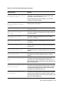
Table 1-4. Configuration Page Settings (continued)
Parameter
Description
Saved in
Default
Limits or alternate choices
NVRAM
POP3 Polling
Interval
Interval printer waits before
checking for new mail
yes
3 minutes
1 to 32767
Printing Password Password required for using
internet printing feature
yes
Not Set
Set
Authorized Hosts List of host connections
allowed to use internet printing
feature
yes
Empty field 256 byte field
Authorized Users
yes
Empty field 256 byte field
List of email names allowed to
use internet printing feature
1-38 ii LINX™ Solid Inkjet 100 Service Manual
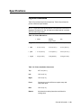
Specifications
Physical Dimensions
Table 1-5 provides the printer dimensions. Table 1-6 provides the
printer clearance requirements.
NOTE: The printer must be mounted on a surface that is flat within 2
degrees of horizontal. All four of the printer’s feet must be in contact
with the mounting surface.
Table 1-5. Printer Dimensions
Printer
Auxiliary
Cart
Feeder Unit
Height
38.8 cm (15.3 in.)
12.7 cm (5.0 in.)
47.6 cm (18.75 in.)
Width
43.2 cm (17.0 in.)
43.2 cm (17.0 in.)
45.7 cm (18.0 in.)
Depth
59.7 cm (23.5 in.)
59.7 cm (23.5 in.)
55.2 cm (21.75 in.)
Weight
36.0 Kg (79 lbs.)
11.8 Kg (26 lbs.)
23.4 Kg (51.5 lbs.)
Table 1-6. Printer Installation Clearances
Top
45.7 cm (18 in.)
Left
10.2 cm (4 in.)
Right
10.2 cm (4 in.)
Front
Clearance must be sufficient to replace trays and
clear paper jams.
Rear
10.2 cm (4 in.)
Bottom
No obstruction under printer that could block its
cooling vents.
General Information
1-39
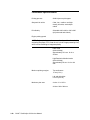
Functional Specifications
Printing process
Solid inkjet onto plain paper
Grayscale ink sticks
Clear, low-, medium- and highdensity ink sticks, each shapecoded
Print Quality
Selectable 409 x 409, or 600 x 600
dpi (horizontal and vertical)
Engine printing speed
NOTE: Engine printing speed measures the elapsed time from loading
to ejecting the paper. Print times do not include image processing time,
which varies according to image complexity.
Draft mode
(409 x 409 dpi)
Approximately 12.8 sec. for A or
A4 size
High Resolution Medical mode
(600 x 600 dpi)
Approximately 25 sec. for A or A4
size
Minimum printing margins
Top and bottom
5 mm (0.2 in.)
Left and right sides
6.5 mm (0.26 in.)
Maximum print area
A size: 8.1 x 10.5 in.
A4 size: 200 x 284 mm
1-40 ii LINX™ Solid Inkjet 100 Service Manual
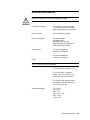
Electrical specifications
Do not use extension cords of any length or gauge.
WARNING
Primary line voltages
87–132 VAC (115 VAC nominal)
174–264 VAC (220 VAC nominal)
Input voltage range is auto-sensed.
Primary voltage
47–63 Hz frequency range
Power consumption
200 watts standby
300 watts at idle
600 watts during printing
Maximum power consumption is
1000 watts during warmup.
Current rating
115 VAC configuration:
8 amp max./1 amp min.
220 VAC configuration:
4 amp max./1 amp min.
Fusing
NOTE: Fuses are not user-accessible.
F1: (DC switcher) 6.3-amp slo blo
F2: (Drum heater 1, reservoir
heater 1, ink melt chambers, cap/
wipe/purge unit) 10-amp slo blo
F3: (Jet stack left and right, paper
pre-heaters, reservoir heaters 2, 3
and 4) 10-amp slo blo
Secondary voltages
+5V ± 2.5%
+12 V ± 5%
-12 V ± 5%
+40 V -5%, +12%
-52 V ± 10%
+54 V ± 10%
General Information
1-41
Operate printer only within specified environmental ranges.
CAUTION
Environmental specifications
If combustible fluids are brought into contact with hot elements of
the printer, evacuate the area and call for service personnel.
WARNING
Temperature
Operating
15-32 C° (59 to 90° F)
Storage and shipping
-30 to 60° C (-22 to 140° F)
Humidity
Operating
15 to 80% relative humidity,
non-condensing
Nonoperating
15 to 95% relative humidity,
non-condensing
Altitude
Operating
0 to 2400 m (8,000 ft.) at 25°C
Nonoperating
0 to 15000 m (50,000 ft.)
Vibration/shock
Nonoperating (vibration)
Will withstand 0.5 G excitation, 5 to 500
Hz, 3 axes for up to 7 minutes with no
impairment or subsequent damage.
Nonoperating (shock)
0.5 g, 25 minute sweep, 5-200-5 Hz,
100–200 sec./sweep cycles
Operating (shock)
The printer may have any corner raised
and dropped 1.5 cm (0.6 in.) while printing
is in progress, without impairment of
operation that cannot be recovered by a
printhead purge cycle. The printer may
1-42 ii LINX™ Solid Inkjet 100 Service Manual
have any corner raised and dropped 6 cm
(2.4 in.) while idle without subsequent
impairment of operation.
Operating (drop)
Printer only with the main tray installed;
maintenance drawer installed; printhead
unlocked; no internal packaging: 0.5 in for
one drop on all four bottom edges
Printer in “Ready” mode and at operating
temperature: 1.0 in. drop on all four bottom
edges
General Information
1-43
Theory of Operation
This topic covers the following subassemblies and diagram within the
printer:
•
Functional block diagram
•
Drum/transfix assembly
•
Maintenance drawer
•
Printhead
•
X-axis movement
•
Printhead tilt mechanism
•
Ink loader
•
Cap/wipe/purge assembly
•
Power supply
•
Power control board
•
Main board
•
Optional Ethernet interface card (100 BaseT)
•
Optional internal disk drive
•
Print process in operation
•
Printhead maintenance cycle
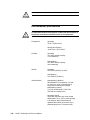
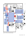
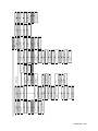
Functional Block Diagram
Figure 1-14 presents a functional block diagram of the printer.
1-44 ii LINX™ Solid Inkjet 100 Service Manual
Figure 1-14. Printer Functional Block Diagram
General Information
1-45
Process motor
position encoder
Process
motor
Y-axis
motor
Main
fan
Size A/A4
empty
tray present
Drum
encoder sensor
Drum
maintenance
cam clutch
Preheater
exit sensor
Pick
clutch
Upper feed
roller clutch
Drum
home
sensor
Process gear
position sensor
Drum temperature sensor 2
High capacity
paper tray 1
11
2
2
2
J 150
2
J 990
J 970
3
J 170
2
2
4
3
Printer ID
I2 C
10
6
Top cover
switch
Front panel
board
Preheat entry
left edge sensor
A4-size sensor
A-size sensor
Handfeed sensor
Printhead
Front cover
switch
120
PCI
CIA
I2 C 4
2
2
4
4
Ink
loader
Cap/Wipe/
Purge unit
Ink
Low
load
empty
board cover
Duplex paper
sensor (not used)
Cap/Wipe/Purge
unit home sensor
Drum maint.
cam home sensor
Pick sensor
Empty sensor
Paper/OHP sensor
A/A4-size sensor
Tray present sensor
5
3
2
2
2
2
Drum
fan
X-axis
motor
Paper
preheater
Drum
heater
Transfix exit
sensor
Exit/tray full
sensor
0388-57
Transfix solenoid
Cap/Wipe/Purge
clutch
Air valve
solenoid
Vacuum
pump
Vacuum/pump
module
Paper feed/
Cap wipe drive
motor
Drum
maintenance
counter EEPROM
6 AC
8 AC
Right I/O
board
I2 C
10
8 18 15
Power
supply
I2 C 10
IDE
hard
drive
I2 C AC
misc 8
10
120
Network
card
PCI
Power control board
120 120
ROM
J 140
Left I/O
board
3
J 180
4
I2 C
SDRAM
SDRAM
Main Board
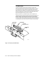
Drum/Transfix Assembly
The drum/transfix assembly (Figure 1-15) forms the key portion of
the printer where imaging takes place. The main features of the
drum/transfix assembly (Figure 1-16) are the drum and transfix
roller. In operation, the image to be printed on paper is first “printed”
on the rapidly rotating drum. A sheet of paper heated by the paper
preheater is then passed between the drum (now rotating much more
slowly) and the transfix roller. Under the pressure between the drum
and the transfix roller, the image is transferred to the sheet of paper.
Transfix roller
r
pe
th
pa
Pa
Paper preheater
Drum
heater
Drum
Figure 1-15. The Drum And Its Systems
1-46 ii LINX™ Solid Inkjet 100 Service Manual
840-4-45
Encoder
disk
Home
sensor
Temperature
sensor (~55°C)
Home
flag
Drum
Encoder
Transfix roller
Fan
Paper/drum
heater
Entry
assembly
Servo motor
Warning: Closed-loop
servo drive
Belt drive
840-4-47
Figure 1-16. Drum/Transfix Assembly
An encoder disk and sensor on the left end of the drum monitors the
drum’s speed as well as its “home” position. The drum heater heats
the surface of the drum to about 55o C (131o F) for imaging. A
temperature sensor in contact with the drum surface monitors the
drum temperature. The main board interprets the sensor’s signal and
turns on the drum heater and drum fan to heat the drum, or turns on
the drum fan alone to cool the drum.
The drum is driven by a closed-loop servo motor which, through a
double reduction belt drive, rotates the drum at a high speed for
imaging and a constant low speed for image transfer to paper.
WARNING
Keep your fingers away from the drum drive system; it uses a
closed-loop drive system. A closed-loop servo drive system is
inherently dangerous. Since the motor speeds up if it senses the
drum drive system slowing down, fingers caught in the drum belts
and gears can be severely injured.
General Information
1-47
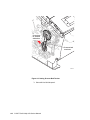
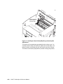
Maintenance Drawer
The maintenance drawer performs two functions. Its primary function
is to create a thin intermediate liquid transfer surface, a layer of
silicone oil, on the surface of the drum prior to printing. The oil keeps
the ink from sticking to the drum’s surface and facilitates its transfer
to the sheet of paper. The oil is contained in an oil saturated roller.
The drum maintenance drawer’s second function is to collect waste
ink from printhead purges in a waste tray. Refer to Figure 1-17.
Camshaft
home
position
flag
Drum
maintenance
drawer camshaft
Process motor
Process drive belt
Maintenance drawer
camshaft electric clutch
Maintenance
drawer
Oil roller
Drum
Actuator
Oil on
Blade drum
Cam pushes oil
roller and blade
against drum
Drum
Cam lowers oil
roller and blade
assembly
840-4-54
Figure 1-17. Drum Maintenance Drawer
Prior to each print, a cam, driven by the process motor, raises the oil
roller against the slowly rotating drum. A compliant blade, also raised
by the same cam, assures that the oil film is smooth and even across
the drum’s surface. The blade also directs excess oil back through a
1-48 ii LINX™ Solid Inkjet 100 Service Manual
felt filter to the oil roller for reuse. As the drum completes one
rotation, the rotating cam lowers the oil roller and then a moment
later, lowers the blade.
A removable NVRAM chip, mounted on the drawer, stores the number
of oiling cycles performed by the maintenance drawer.
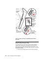
Printhead
The printhead (Figure 1-18) is the heart of the printer. Refer to Figure
1-17. The printhead spans nearly the length of the drum. Using its
448 ink-jet nozzles (112 jets for each density), with a horizontal
motion of slightly more than 5 mm (0.2 inches), the printhead can
print the entire image on the rotating drum.
Reservoir
Drum
Jet stack
Head drive board
Printhead
840-4-48
Figure 1-18. Printhead
General Information
1-49
Figure 1-19 shows a cross-section of the inkjet array and the jet
nozzle arrangement.
The printhead’s jet stack is fabricated from a stack of chemically
etched steel plates which are brazed together to form the ink-jet
array. Channels formed by the stacked plates route ink past the 448
individual, piezoelectric crystal-driven diaphragms, which force the
ink in droplets out the 448 corresponding nozzles. Looking at the
printhead face, the nozzles are arranged in four rows with the
intermediate density nozzles forming the top row, the low density
nozzles forming the next row 22 /300” below, and the clear nozzles
forming the third row 11/300” below and the high density nozzles
forming the fourth row 22/33” below. During the printing process, the
printhead would only have to travel 22 pixels horizontally to provide
complete coverage. (In actuality, the printhead travels much further
to interlace with the output of neighboring jets.)
The Drift Compensation setting in the hidden Service Support menu
enables automatic drift compensation. When it is turned on, it slowly
increases the printhead drive voltage over time to maintain optimal
printhead performance.
1-50 ii LINX™ Solid Inkjet 100 Service Manual
Ink inlet
Manifolds
Piezoelectric crystals
Intermediate
22 pixels
Low
22 pixels*
Clear
11 pixels*
High
22 pixels*
* 300 dpi pixels
840-4-49
Figure 1-19. Printhead Detail
The ink-jet array is bonded to a cast aluminum ink reservoir. The
reservoir supplies the molten ink to the ink-jet array. Heaters in the
reservoir and the ink-jet array maintain the ink at a temperature of
about 140o C for printing. The level of the ink in the reservoir is kept
at a constant level.
General Information
1-51
X-axis Movement
X-axis or lateral movement of the printhead is accomplished using a
stepper motor driving a fine-thread leadscrew. The printhead,
mounted to the X-axis shaft, moves right and left across the surface of
the drum.
To find the printhead home position, the X-axis system drives the
printhead in an open loop. The printhead is driven against the left
printer frame for a few seconds, and then reversed a set number of
steps.
A spring attached to the printhead and right printer frame, provides
a preloaded tension so the printhead moves smoothly.
X-Axis shaft
Tension spring
Printhead
Drum
Drive gear
X-Axis Motor
X-Axis shaft
Frame
Frame
Nose cone gear
840-4-50
Figure 1-20. X-axis Printhead Movement During Printing
1-52 ii LINX™ Solid Inkjet 100 Service Manual
Printhead Tilting Mechanism
To accommodate printhead maintenance, the printhead can be tilted
back away from the drum. (Refer to Figures 1-21 and 1-22.) This
creates room for the cap/wipe/purge assembly to be moved into
position in front of the printhead faceplate. The printhead tilts back
on its X-axis shaft that it travels on. The X-axis shaft is connected to
the head tilt arm. At the lower end of the arm is a cam-follower. The
cam follower (and tilt arm) respond to the movement of the head tilt
cam gear. As the gear rotates, the arm follows the motion and tilts
back the printhead.
Printhead
print position
Return
spring
Printhead
Drum
Head tilt arm
X-axis shaft
Cam follower
rim
Drive gear
not
engaged
Tilt cam
gear
Cam
Printhead
maintenance position
Leaf
spring
Leaf spring tension
engages drive gear
840-4-57
Figure 1-21. Printhead Tilting Operation
General Information
1-53
A return spring at the top of the tilt arm pulls the printhead toward
the drum.
In the print position, the tilt arm gear’s missing teeth are positioned
at the tilt arm gear’s drive gear. When actuated, a leaf spring pushes
against a cam lobe on the backside of the tilt cam gear to give the tilt
cam gear a slight rotation and engage its teeth to the drive gear. The
leaf spring is held away from the cam lobe of the tilt cam gear by the
cap/wipe/purge assembly in its standby position. Slightly raising the
cap/ wipe/purge assembly releases the leaf spring and allows it to
push the cam lobe and rotate the tilt arm gear slightly.
Head tilt arm
Cam follower
Head tilt
cam gear
Process
motor
Process drive
compound
gear
Head tilt cam
gear disengaged
from drive gear
Figure 1-22. Printhead Tilting Mechanism
1-54 ii LINX™ Solid Inkjet 100 Service Manual
840-4-55
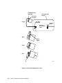
Ink Loader
The ink loader consists of four parallel channels with an ink melting
element at the end of each of the four channels. (Refer to Figure 1-23.)
Ink sticks, one color loaded in each channel, are pressed by coil-spring
pressure into the melting elements. As ink is required by the
printhead, the appropriate color’s melting element is activated and
the end of the ink stick is melted. The melted ink drips into the ink
reservoirs of the printhead underneath. Sensors in the ink loader
alert the customer to install more ink sticks before the current sticks
are completely consumed.
If the ink level sensors inside the printhead detect that the printhead
has run out of ink, but the ink low/out sensors are not activated, the
front panel reports an “Ink Jam” error.
Ink loader door
Ink stick
Ink melt
units
Ink low
sensor
Coil spring
Ink out
sensor
Printhead
840-4-46
Figure 1-23. Ink Loader
General Information
1-55
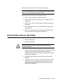
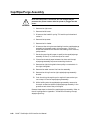
Cap/Wipe/Purge Assembly
The cap/wipe/purge assembly is a long, shallow cup with an
elastomeric gasket. (Refer to Figure 1-24.) When raised and pressed
against the face of the printhead, it forms an airtight seal. After
forming the seal, a partial vacuum is applied to the faceplate to suck
out air bubbles and any debris that may be obstructing the printhead
nozzles. Following the vacuum cycle, the cap/wipe/ purge assembly
performs a wipe operation on the faceplate using its squeegee-like
wiper blade. The cap/wipe/purge assembly also receives the ink
ejected from the printhead during the flush portion of the printhead
maintenance cycle. The flushed ink is routed to the waste tray of the
drum maintenance drawer. The cap/wipe/purge assembly is heated to
keep the waste ink fluid during the wipe and purge operations.
Cap/Wipe/Purge assembly transport
Cap/Wipe/Purge
assembly
Printhead
Cap/Wipe/Purge
assembly home
sensor
(on I/O board right)
Drum
Cap/Wipe/Purge
assembly belt
Vacuum system
Solenoid valve
"unenergized"
Air
Pump
Vacuum
accumulator
Filter
Air
7 mil
orifice
Cap/Wipe/Purge
assembly
Solenoid valve
"energized"
840-4-56
Figure 1-24. Cap/Wipe/Purge Assembly
1-56 ii LINX™ Solid Inkjet 100 Service Manual
The cap/wipe/purge assembly is attached to a pair of parallel belts on
a rotating shaft. To perform a printhead maintenance cycle, the
printhead is first tilted away from the drum. Then the cap/wipe/purge
assembly motor drives the cap/wipe/purge assembly belts, which pull
the attached cap/wipe/ purge assembly up to the faceplate of the
printhead. The printhead is then tilted forward to seal against the
cap/wipe/purge assembly.
When the cap/wipe/purge assembly is in its lowered home position, it
unlocks the maintenance drawer so it can be removed. If the cap/
wipe/purge assembly is away from its home position the drum
maintenance drawer is locked in place.
When servicing the printer be careful of the cap/wipe/purge
assembly as it passes the printhead. If a damaged wiper blade of
the cap/wipe/purge assembly catches on the printhead it could
propel hot liquid ink upward into your face.
WARNING
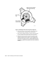
Vacuum for the purge cycle is obtained from the vacuum/pump
module which contains a vacuum pump and an air valve solenoid
(Figure 1-25). The body of the vacuum/pump module forms a vacuum
accumulator. A small vacuum pump, running for 75 to 90 seconds,
creates a strong vacuum in the vacuum accumulator. Then an air
valve is energized for a fraction of a second, exposing the printhead
faceplate to the strong, accumulated vacuum to suck debris and
bubbles out of the printhead nozzles. With the air valve once again deenergized, air is metered through the 7-mil orifice to gradually
release the vacuum at the faceplate.
General Information
1-57
Cap/Wipe/Purge
assembly
Vacuum/Pump
module
Printhead
faceplate
Purge
Air valve
solenoid
Vacuum
pump
Vacuum
accumulator
space
Wipe
Wiper
blade
Flush
Dab
840-4-51
Figure 1-245 Cap/Wipe/Purge Assembly and Vacuum System
1-58 ii LINX™ Solid Inkjet 100 Service Manual
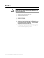
Power Supply
The power supply has two main, yet interrelated sections: the AC
section and the DC section. In the AC section, power is routed to 14
opto-isolated triacs which, under main board logic control, supply AC
power to the 14 heaters in the printer.
Two fuses provide current protection to the triacs. Fuse F2 and F3
protect the power supply from, most often, a shorted triac caused by a
defective heater. If F2 or F3 fuse blows, it is best to replace the power
supply (and, of course, the defective heater), rather than the fuse.
Otherwise, with the fuse replaced, but the triac shorted, AC power
may be applied to the heater without the printer even being turned
on. Each time the main board turns on a triac to activate a heater, it
is turned on for only a fraction of a second. The main board must
constantly readdress each heater it wants to remain on. By this
means, if the print engine firmware should fail, the heaters
automatically shut off. The printer is also protected by thermal fuses
located inside: two fuses for the drum heater, and one each for the
paper preheater and the cap/wipe/purge assembly. A thermal fuse
opens in the unlikely event of a “runaway” heater following a
firmware failure.
The DC power supply generates +5 volts for the printer’s logic, + 40
volts for the motors, +54 volts and -52 volts for the printhead drivers,
and ±12 volts for fans. Fuse F1 provides protection for the switching
power supply in the DC section. The block diagram for the power
supply is illustrated in Figure 1-26.
WARNING
Do not touch the power supply; AC line voltages are present. The
power-switch does not interrupt AC power to the power supply, it
only signals the supply and the printer logic to begin a shutdown
sequence. Even with the power switch in the OFF position, AC line
voltages are present on the power supply, heaters and heater
wiring.
There are no field adjustments necessary on the power supply.
General Information
1-59
F1
F2
+5 V
+40 V
+54 V
-52 V
+12 V
-12 V
F° Drum heater 1
F° Reservoir heater 1
High density
ink melter
Intermediate density
ink melter
Power
on
Low density
ink melter
Clear ink melter
Cap/wipe/purge
unit heater
Reservoir heater 3
AC
in
F3
Jet stack left
Paper pre-heater
Jet stack right
Reservoir heater 2
Drum heater 2
Triac control
lines from
the power
control board
Reservoir heater 4
Figure 1-26. Power Supply Block Diagram
1-60 ii LINX™ Solid Inkjet 100 Service Manual
840-4-66
Print Process in Operation
Once an image has been processed and a printing bitmap created, a
print cycle begins. The printhead and drum are brought up to their
operating temperatures and the ink levels in the ink reservoirs are
checked and ink is added from the ink loader, if necessary. Next, the
printhead is driven horizontally to its home position and the drum is
rotated to its home position.
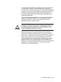
WARNING
Keep your fingers away from the process gear drive system; it uses
a closed-loop drive system. A closed-loop servo drive system is
inherently dangerous. Since the motor speeds up if it senses the
process gears drive system slowing down, fingers caught in the
process belts and gears can be severely injured.
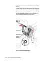
Printhead Tilt
The printhead is tilted forward into its print position. (Refer to Figure
1-27.) The process motor is activated, which drives the process drive
belt. The belt, in turn, drives a compound gear. Through a follower
gear, the compound gear drives the head tilt cam gear clockwise. A
cam follower, mounted on the lower end of the head tilt arm, follows
the rotating cam gear, which tilts the printhead. The head tilt cam
gear rotates until a set of missing teeth in the cam gear “disengage” it
from the cam drive gear. The cap/wipe/purge assembly, in its standby
position, draws a leaf spring away from a cam lobe located at the back
side of the tilt arm gear. (When the leaf spring pushes against the
cam lobe of the tilt arm gear it forces the gear to mesh with the cam
drive gear.) Pulling the leaf spring away effectively latches the head
tilt cam gear in the printhead forward position. At this point, the
printhead is in its upright print position (home position). (The head
tilt cam gear is principally rotated in a counterclockwise direction to
tilt the printhead forward and back. It only rotates clockwise during
some printhead cleaning operations.)
Tilted forward, the missing teeth of the head tilt cam gear allow the
process motor and gear train to perform other print functions without
affecting the printhead’s tilt position. The cap/wipe/purge assembly is
raised slightly to allow the head tilt cam gear (with a slight spring
assist from the leaf spring pushing against the cam lobe on the back
of the tilt cam gear) to advance forward enough to engage its drive
gear and tilt the printhead back.
General Information
1-61
Head tilt arm
Cam follower
Head tilt
cam gear
Process
motor
Process drive
compound
gear
Head tilt cam
gear disengaged
from drive gear
Figure 1-27. Tilting The Printhead
1-62 ii LINX™ Solid Inkjet 100 Service Manual
840-4-55
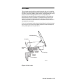
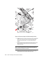
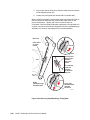
Drum Preparation
To prepare the drum, a thin, intermediate liquid transfer surface is
applied to the surface of the drum. (Refer to Figure 1-28.) First the
drum is rotated to a speed of 51 cm per second (20 inches per second).
Next, the oil roller and blade of the maintenance drawer are raised
into contact with the drum. To accomplish this, the process motor
rotates clockwise, driving the process drive belt and the compound
gear. Rotating clockwise, the compound gear drives a gear train that
drives the maintenance camshaft’s 3-position electric clutch which, in
turn, engages the maintenance drawer camshaft. The maintenance
drawer camshaft clutch energizes to release the 3-position clutch,
allowing it and the camshaft to rotate about one-half revolution to the
next stop. The cams on the ends of the camshaft push against
followers on each side of the maintenance drawer, forcing the oil roller
and blade against the drum. The de-energized clutch holds the
camshaft in this position.
As the drum nears the end of its rotation, the clutch energizes for a
moment, allowing the camshaft to rotate further; this lowers the oil
roller but leaves the blade in contact with the drum to smooth out the
last of the oil on the drum.
The clutch energizes for a third time to allow the camshaft to rotate
to its home position, and lower the blade. The point at which the blade
ends contact with the drum leaves a bead of oil, called an oil bar. The
oil bar defines the edge of a 40 mm (1.5 in.) swath of the drum which
is not oiled; this swath is called the deadband. No ink will be
deposited on the deadband during the print cycle. Instead, the paper
stripper fingers, which lift the paper off of the drum during printing,
are lowered into contact with the drum in the deadband. This keeps
them from accumulating any oil on their fingertips which would stain
the edge of the print as it is stripped off of the drum.
At this point, the drum starts rotating again at a speed dependent
upon print resolution. As the drum reaches the correct speed, the inkjets begin to fire to deposit the image on the oiled portion of the drum.
As the jets fire, the printhead slews in the X-axis to complete the
image on the drum.
General Information
1-63
Camshaft
home
position
flag
Drum
maintenance
drawer camshaft
Process motor
Process drive belt
Maintenance drawer
camshaft electric clutch
Maintenance
drawer
Oil roller
Drum
Actuator
Oil on
Blade drum
Cam pushes oil
roller and blade
against drum
Drum
Cam lowers oil
roller and blade
assembly
840-4-54
Figure 1-28. Drum Preparation For Printing
1-64 ii LINX™ Solid Inkjet 100 Service Manual
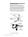
Printing
When printing, the printer performs a “four-jet interlace” in which
each jet lays down a particular number of pixel columns depending on
the print resolution. Each jet lays down one pixel column for each
drum rotation; this varies from 30 to 44 rotations (30 @ 409 dpi and
44 @ 600 dpi). Each jet travels horizontally the distance of 125 to
181 pixels (125 @ 409 dpi and 183 @ 600 dpi) to lay down its 30 to
44 pixel columns within that pixel field. The 125 to 181 pixel-wide
field of each jet overlaps the pixel field of six other jets; this is where
interlacing occurs.
During the horizontal movement of the printhead, extra 1 or 2-step
movements are made to properly align the pixel columns and prevent
a column from overlapping another column. The actual number of
steps depends on the print resolution.
Physically, each jet is horizontally located 22/300 of an inch from its
neighbor.
Interlacing “averages out” the variability between jets by interlacing
each jet with three other jets. As shown in the Figure 1-28, of the
pixel columns printed by any single jet, only two of its pixel columns
are actually ever adjacent. Usually they are separated by three other
pixel columns produced by other jets, hence the name four-jet
interlace. Because of the physical spacing between jets and the pixel
field that each jet travels, the pixel columns of any one jet actually
interlaces with the pixel columns of six other jets, although no more
than four at any one time.
During some diagnostic printing, such as the Cleaning Test Print, the
printhead slews to the right and lays down 112 parallel bands of ink.
Each band is about 1.86 mm (0.073 inch) wide and is composed of 30
pixel columns of dots from an individual jet. As the printhead slews to
the right, the drum rotates 30 times; the number of pixel columns
each set of jets deposits on the drum. (A set of jets is one of the 112
vertical arrangements of low density, medium density, clear and high
density jets.) With no interlacing, the test print reveals the
deficiencies of a single jet compared to the rest. Only in the Test Print
2: Weak/Missing Jets (I-mode) and the Print Jets Test Page test print,
does the printhead simply slew sideways with no jet interlacing.
General Information
1-65
125 to 181 pixel-wide
field traveled by a jet
(depending on print
resolution)
Output
of four
side-by-side
jets
1 of 4
2 of 4
3 of 4
4 of 4
22/300"
separation
between jets
Step
Step
Step
4 of 4
3 of 4
2 of 4
1 of 4
Columns of pixel dots
produced by previous set of
four adjacent jets. Note
how the ending columns of
this set interlace with
beginning columns of the
next set of four jets.
Column of pixel
dots produced
by four adjacent
jets are
interlaced
together for
printing. Each
jet produces
between 30 and
44 pixel
columns.
840-4-62
Figure 1-29. Printing Latent (Pre-transferred) Image On The Drum
1-66 ii LINX™ Solid Inkjet 100 Service Manual
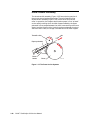
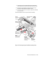
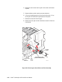
Paper Pick
To pick a sheet of paper, the process motor rotates clockwise, driving
the process drive belt and the compound gear counterclockwise. (Refer
to Figure 1-30.) Rotating counterclockwise, the compound gear turns
and, in turn, engages a gear train that rotates the pick roller clutch
gear counterclockwise. The paper pick electric clutch energizes for a
moment, engaging the paper pick clutch and allowing it to rotate one
revolution. The pick roller rotates and pulls a sheet of paper from the
paper tray. The sheet of paper trips the paper pick sensor to assure
that the paper was picked from the tray. If the paper is not sensed,
the pick solenoid is energized, up to six times, to rotate the pick roller
again to attempt to recover from the mis-pick and pick the sheet of
paper.
With the paper-pick sensed, the paper-feed motor drives the upper
and lower paper-feed rollers and carries the sheet of paper to the
paper preheater. On its way, the sheet of paper passes the deskew
fingers which are flexible, plastic fingers mounted on the front cover.
The deskew fingers guide the paper and create a buckle in the paper
which aligns the paper to the paper path.
The paper stops at the entry to the paper preheater, tripping the
paper preheater entry sensor on the left end of the paper preheater.
The paper also trips the paper width (A/A4-size) sensors on the right
end of the paper preheater to verify that the width of the paper is
within the printer’s specifications. At this point, the paper feed motor
is stopped to wait for more ink deposition on the drum.
When ink deposition is about 95% complete, the paper feed motor is
activated to bring the sheet of paper through the paper preheater and
to the transfix position. The paper preheater heats the paper to
improve ink transfer. The leading edge of the sheet of paper trips the
paper preheater exit sensor as it passes out of the paper preheater.
General Information
1-67
Exit
sensor
Paper
size
sensors
Transfix
exit
sensor
Preheater
exit sensor
Deskew
fingers
Paper preheater
entry sensor
Paper
pick sensor
Upper
feed roller
Upper feed
roller clutch
Pick clutch
Pick
roller
Lower
feed roller
840-4-53
Figure 1-30. Paper picking and positioning for transfixing
1-68 ii LINX™ Solid Inkjet 100 Service Manual
Transfixing, Stripping And Exiting
As the leading edge of the sheet of paper trips the paper preheater
exit sensor, it starts the transfix roller being lowered to its transfix
position. The process motor rotates clockwise, rotating the process
drive compound gear counterclockwise. Fourteen flags on the
circumference of the gear represent the fourteen teeth on the small
gear on the back of the compound gear. When the teeth of the small
gear are in the proper position, as detected by the compound gear
position sensor, the transfix cam solenoid energizes to release the
spring-loaded transfix cam on the right end of the transfix roller
shaft. This allows the transfix roller gear (which up to this point in
time had missing teeth “disengaged” to the 14-tooth gear of the
process drive compound gear), to rotate slightly and engage the small
gear of the compound gear. During this time, the drum, rotating at
about 24 rpm, positions the deadband to coincide with the arrival of
the leading edge of the sheet of paper (which is moving at the same
rate as the drum).
The rotating transfix gear rotates the transfix roller shaft about onehalf revolution. The transfix roller, which is eccentrically mounted on
the transfix roller shaft, rotates into contact with the paper (5 mm
behind the leading edge) and then stops. This sandwiches the leading
edge of the paper between the transfix roller and the beginning of the
image on the drum. The drum’s rotation rotates the transfix roller
and begins to pull the sheet of paper between them. The transfix
roller shaft rotates slightly more so a protrusion on the transfix roller
cam causes the stripper fingers to momentarily drop down onto the
deadband of the drum and catch the leading edge of the sheet of
paper and direct the paper to the rotating exit rollers, which are belt
driven by the paper path motor. The transfix roller shaft rotates
slightly more to clear the protrusion on the transfix roller cam and
raise the stripper fingers so they no longer contact the drum.
The process motor stops, leaving the transfix roller cam in its halfrotated position. Friction from the rotating drum continues to turn
the transfix roller, which freely rotates on the transfix roller shaft.
The ink on the drum transfers to the sheet of paper pulled by the
friction between the drum and the transfix roller. After about 1.8
seconds, the complete image has been transferred to the paper. The
process motor drives the transfix gear until the transfix gear is
completely unloaded. At this point, the transfix gear is disengaged
from the process motor gear, the transfix cam solenoid is latched
again and the transfix roller is lifted off of the drum.
The paper path motor, driving the exit rollers through a drive belt,
pushes the remainder of the sheet of paper into the exit tray. The
trailing edge of the paper is detected by the exit sensor, ending the
print cycle.
General Information
1-69
Transfix roller
on eccentric shaft
Exit
sensor
Transfix
exit
sensor
Paper
preheater
Transfix
roller gear
Transfix
roller
Transfix cam
solenoid
Transfix
roller shaft
Transfix
cam
Process motor
Process drive
compound gear
Compound gear
position sensor
840-4-52
Figure 1-31. Image Transfixing, Stripping and Paper Exiting
1-70 ii LINX™ Solid Inkjet 100 Service Manual
Printer Self-Maintenance
To maintain peak operation, reliability and print quality, the printer
has several automatic or semiautomatic maintenance functions.
(Refer to Figure 1-32.) These functions may be started automatically
after a certain number of prints or during printer startup, or they
may be started by the customer if a print quality defect is noted.
•
Printhead maintenance cycle
•
Paper preheater cleaning
•
Transfix roller oiling
•
Drum cleaning (chase page)
Printhead Maintenance Cycle
This topic describes the cleaning cycles used to remove bubbles or
foreign matter that cause a printhead jet to malfunction. Three basic
actions take place during a cleaning cycle:
•
purging
•
wiping
•
flushing
These actions are used in different combinations for three different
types of cleaning cycles:
•
quick wipe
•
short cleaning
•
long cleaning
The long cleaning cycle is performed automatically when the Clean
Jets menu item is run a second time.
The long cleaning is described here. The short cleaning and the quick
wipe are basically subsets of the long cleaning cycle.
General Information
1-71
Cap/Wipe/Purge
assembly
Vacuum/Pump
module
Printhead
faceplate
Purge
Air valve
solenoid
Vacuum
pump
Vacuum
accumulator
space
Wipe
Wiper
blade
Flush
Dab
840-4-51
Figure 1-32. Printhead Maintenance Cycle
1-72 ii LINX™ Solid Inkjet 100 Service Manual
Preparation. Following printer power-up from a cold start or in
response to a front panel menu selection, the print engine begins a
printhead long cleaning cycle. The first step is to stop any ink melting
operation. The printhead is tilted into the standby position. In this
case, the cam follower follows the rotating cam gear, tilting the
printhead backward. Following the head tilt, the cap/pipe/purge
clutch energizes to engage the cap/wipe/purge timing belts to the
paper path drive system. Then the paper path motor rotates
counterclockwise to pull the cap/wipe/purge assembly into its cleaning
position. Next, the printhead is tilted forward slightly to seal against
the cap/wipe/purge assembly.The vacuum pump turns on for .5
seconds, just before sealing to build a slight vacuum in the
accumulator. The solenoid valve opens as the cap seals on the
printhead to prevent air from being pushed into the printhead. The
cap then moves down a little bit to improve the seal. Then the main
board starts the vacuum pump, which begins to create a vacuum in
the vacuum accumulator. The pressure in the accumulator is lowered
to about 10 psi. It takes the vacuum pump about 75 to 90 seconds to
achieve this vacuum and then the pump is shut off.
Purge. Actual cleaning begins with the air valve solenoid energizing
for 0.300 seconds; this momentarily routes the vacuum accumulator
to the cap/wipe/purge assembly and exposes the printhead faceplate
to the vacuum. The vacuum bleeds off after about 6 seconds through
the 7 mil orifice. This is repeated 3 to 4 times, depending on the purge
type, with 15 seconds between events. Then the printhead is tilted
backward to break the seal and the printer waits 10 seconds for the
waste ink to drain from the cap/wipe/purge assembly into the waste
tray.
Long wipe. The paper path motor slowly rotates clockwise to pull the
cap/wipe/purge assembly’s wiper blade down the face of the
printhead, wiping away ink and debris.
Long flush. The printhead is tilted back slightly and the cap/wipe/
purge assembly is raised to bring the wiper blade even with the jet
nozzles. All jets are fired for 6 seconds to flush mixed ink and foreign
matter out of the jets. The waste ink drips into the waste tray of the
drum maintenance drawer.
Dab. The cap/wipe/purge assembly is lowered slightly and the
printhead is tilted forward to dab the wiper blade against the lower
faceplate, to clean ink off the wiper. The dab is actually a short wipe
and it is done on the part of the faceplate below the nozzles
Short wipe. Following the dab, the cap/wipe/purge assembly is
raised and the printhead is tilted forward against the wiper blade.
The cap/wipe/purge assembly is slowly lowered again to clean the
faceplate but stops sooner, before it can run into the debris from the
first wipe.
Short flush. The printhead is tilted back slightly and the cap/wipe/
purge assembly is raised to bring the wiper blade even with the jet
nozzles. All jets are fired again for 0.6 seconds.
General Information
1-73
Following the second flush, the printhead is tilted back and the cap/
wipe/purge assembly is lowered into its standby position. A cap/wipe/
purge home sensor on I/O board right detects when the cap/wipe/
purge assembly is stored in its standby position. Then the printhead
is tilted forward into its print position and a cleaning or “mud” page is
printed. The cleaning page allows each jet to eject ink that may be
slightly contaminated with another ink.
7 day flush. If no printhead clean cycle has been run for 7 days, the
printer automatically performs a printhead flush to expel old ink
from the printhead orifices. This gets rid of any old, “cooked” ink and
improves printhead reliability.
Paper Preheater Cleaning
This is a customer-initiated cleaning procedure, selected through the
front panel troubleshooting menu Remove Ink Smears. The purpose of
this cleaning item is to clean ink out of the paper preheater that may
have been deposited there. Ink can be deposited if a jammed print,
with ink on it, was pulled backwards through the paper preheater.
Heavier-weight, high-grade quality bond paper works best for this
procedure.
In the paper preheater clean cycle, these events take place:
The user starts the Remove Ink Smears menu item.
1. The printer overheats the paper preheater to 100o C, softening
ink trapped inside the paper preheater. Ordinarily the paper
preheater runs at temperatures of between 60 and 65o C for
paper printing.
2. The printer picks and passes up to 25 sheets of paper through
the print path. Each sheet absorbs and removes ink from the
paper preheater, but only the first five sheets are chased at the
elevated temperature. Then up to 20 additional sheets are
chased while the preheater cools down. The sheets are cleaning,
but their main function is to bring the preheater temperature
back down. The total number of chase sheets will vary from
situation to situation. The printer can resume printing when
the preheat temperature drops to 75˚C or below.
3. The printer returns to the Troubleshooting menu.
Because of the higher paper temperatures involved, this function can
also be used to clean the drum surface of ink deposits caused by a
contaminated blade on the drum maintenance drawer.
1-74 ii LINX™ Solid Inkjet 100 Service Manual
Transfix Roller Oiling
At the first opportunity after making 50 prints when no prints are
queued and the printer is idle, the printer performs a transfix roller
oiling cycle. During this cycle, oil is applied to the drum as it would be
during a print cycle. Then the transfix roller is lowered against the
drum and the drum rotates; this transfers some of the oil to the
transfix roller, then the transfix roller is raised to its standby
position. Oiling the transfix roller prevents ink and media from
sticking to the transfix roller.
Drum Cleaning (Chase Page)
The printer performs a drum cleaning with a chase page
automatically anytime a paper jam occurs after an image has been
“printed” on the drum. The chase page transfers the image, which
may not be complete, off the drum and is usually discarded. The
printer then attempts to reprint the print that jammed. The chase
page is processed the same as a regular print except the drum is not
oiled and no image is printed on the drum (since an image is already
printed on the drum).
General Information
1-75
Power Control Board
The power control board functions as a back plane. This circuit board
is the point of electrical interface to the print head, main controller,
optional Ethernet Interface card, internal hard disk drive, I/O boards.
and power supply. The PCI bus signals supporting the optional
Ethernet Interface card and internal disk drive are sourced from the
image processing controller and are routed to the option slots on the
power control board. Two optional PCI based boards: optional
Ethernet Interface and Internal Disk Drive are available and plug
into the power control board (back plane). Only one Ethernet
interface is supported at a time. If an optional Ethernet Interface card
is plugged into the printer, the printer’s on-board 10 Base T Ethernet
is disabled.
Main Board
The power control board contains all of the motor power drivers with
actual control for the drivers located on the main controller. Switching
for all heaters is contained in the power supply.
The main controller, or processing controller, uses a Motorola
PowerPC 603e running at a nominal bus frequency of 32 MHz. The
603e PLL is configured for 4:1 operation resulting in a CPU frequency
of 128 Mhz. DRAM is interfaced with a 64 bit bus and the PCI bus is
32 bits wide running at 33 MHz. Other interfaces in addition to PCI
bus are parallel port, serial port, and USB device side port.
There are two dram (SDRAM) DIMM sockets on the board. These will
accommodate industry standard 64 MB SDRAM modules up to a total
of 128 MB.
There is one 168 pin DIMM socket for ROM/FLASH on the main
controller. The interface to the controller is 64 bits.
Four DIP switches are located on the rear panel and from left to right
are: Service Mode 3. Service Mode 2, Service Mode 1 and System
Reset. The Three service Mode switches are defined by software and
the System Reset is hardwired. After initialization both the
PostScript and Engine LEDs blink to indicate normal operation. The
Postscript and Engine LEDs are located to the left and right of the
DIP switch respectively.
The Ethernet connector contains two integral LEDs. The yellow
indicates transmit and green indicates receive.
The image processing controller contains an on-board Digital
Semiconductor 21041-AB 10 Base T Ethernet port located at JR160.
The controller’s built-in Ethernet interface will support 10Mbit halfduplex Ethernet connections over category 3 (or higher) twisted pair
cable and is automatically disabled when the optional 100 base T
interface is installed.
Both the IEEE 1284 parallel port and the serial ports are
1-76 ii LINX™ Solid Inkjet 100 Service Manual
implemented using a Cirrus Logic CL-CD1284. The parallel port uses
a 36 pin IEEE 1284 connector on the rear panel. The serial port
provides RX and TX only with no handshaking. It is connected via a 5
pin square post 0.1" centers connector recessed into the rear panel.
The CL-CD1284 general purpose 8-bit parallel 55º port is used for the
following functions:
BIT # FUNCTION
0
1
2
3
4
5
6
7
Input
Input
Input
Output
Input
Input
Input
Output
DESCRIPTION
Service mode switch 1
Service mode switch 2
Service mode switch 3
Reset control tor NETCHIP 2890
Bit 1 of the 2 bit board version number
Bit 2 of the 2 bit board version number
Parallel Port master ready (host logic high)
Parallel slave ready (peripheral logic high)
Optional Ethernet Interface Card (100 Base T)
The optional Ethernet Interface card has an RJ-45 connector, a 50ohm BNC (coax) connector and four LEDs on the rear panel. The card
includes a DEC 21143 Ethernet MAC, an ICS 1890 MII PHY and an
82C92 coax transceiver. There are no jumper or switch settings on the
card. It supports 100Mbit connections over the RJ-45 connector using
two pairs of category 5 cable at up to 100 meters (l00 Base-TX), or
10Mbit connections over the same connector using two pairs of
category 3 (or greater) cable at up to 300 meters (10 Base-T). The card
fully supports 802.3u clause 28 autonegotiation with parallel
detection at 10 and 100 Mbits/sec on the RJ45 port. When connected
to a hub switch port, the printer will determine the best possible
speed and duplex setting, either 100Base-TX full-duplex, 100Base IX
half-duplex, 10Base-T full-duplex or l0Base T half-duplex. If the RJ45 port is not connected or the link to the hub/switch fails (e.g. due to
a cable fault), the card will switch to 10Mbit/sec half-duplex operation
over the coax (BNC) interface. Users should not connect cables to both
ports; doing so will not disrupt the customer’s network but may
prevent the printer from communicating properly.
The operating mode of the interface may be determined from the
Network Type parameter or by observation of the back-panel LEDs.
There are four LEDs mounted in a square pattern. The upper two
LEDs are yellow; the bottom two are green. The left-hand pair of
LEDs indicate activity: the green LED will flash when the card is
receiving data from the network and the yellow LED will flash when
the card transmits data to the network. The right-hand pair of LEDs
indicate the operating mode. The top right yellow LED will be on
when the speed is 100Mbits. It is off for l0Mbits. The bottom right
green LED will be on when the twisted-pair (11145) connector is in
use and there is a good link to a hub. It will be off if the link fails or
when the coax (BNC) connector is selected.
General Information
1-77
Optional Internal Disk Drive
The internal disk drive board contains a 3.2 Gigabyte IDE disk drive
interfaced to the 32 bit PCI bus using a CMD Technology PCI646 PCI
to IDE data conversion chip. Disk drive data transfer rates are 3.5
Mbytes/sec minimum and 5 Mbytes/sec maximum and are 16 bits
wide.
1-78 ii LINX™ Solid Inkjet 100 Service Manual
Chapter
Error Codes and Messages 2-1
Chapter 2
Error Codes and Messages
This chapter provides a description of the error codes and messages.
Rear panel LEDs error codes . . . . . . . . . . . . . . . . . . . . . . . . . . . .
2-2
iiLINX™ Solid Inkjet 100 Service Manual
2-x
Rear Panel LEDs Error Codes
The rear panel LEDs are located on each side of the rear panel DIP
switches.
NOTE: All references to right and left are as viewed from the reat of
the printer.
The left LED represents the operation of the PostScript firmware.
The right LED represents operation of the main board’s print engine
firmware. During the Power On Self Tests (POST), the two LEDs
toggle back and forth for each successful pass through each SDRAM
test. A failure in the power on self tests is indicated by the left LED
(the PS LED) flashing in a specific pattern of long and/or short
flashes and repeated indefinitely. A long flash represents a 5, while a
short flash is a 1. For example, a long flash followed by 4 short
flashes is 5 + 4 = 9. If the left LED repeatedly flashes in the same
sequence, then the PostScript processor has encountered an error and
is looping. The possible LED-encoded error codes are listed in Table
2-1. Other failures are indicated by the failure being printed on the
Startup Page.
Table 2-1. Main Board Power-up Self-test Error Codes
Left LED
Flashes
Long flash=5
Short flash=1
2L+ 1S=11
Meaning
Details
1
not used
2
SDRAM SIMM Presence
This test verifies for the presence of both
SDRAM SIMMs. If both SDRAM SIMMs are
missing, the resultant error indication is 2 short
flashes from the left LED.
3
SDRAM Bank 0
This test verifies DRAM Bank 0 in the DRAM
DIMM located in position 0 (closest to the rear
panel.)
4
SDRAM Bank 1
This test verifies DRAM Bank 1 in the DRAM
DIMM located in position 0 (closest to the rear
panel.)
5
SDRAM Bank 2
This test verifies DRAM Bank 0 in the DRAM
DIMM located in position 1 (farthest from the rear
panel.)
6
SDRAM Bank 3
This test verifies DRAM Bank 1 in the DRAM
DIMM located in Position 1 (farthest from the rear
panel.)
7
not used
8
not used
Error Codes and Messages 2-3
Table 2-1. Main Board Power-up Self-test Error Codes (continued)
Left LED
Flashes
Long flash=5
Short flash=1
2L+ 1S=11
Meaning
Details
9
NVRAM
This test does a walking 1's and a walking 0's
test for the last 4 bytes in the VXWorks section
of the NVRAM.
10
EPROM
This test verifies in the first 24 bytes from the
EPROM that verifies that the Tektronix Ethernet
address 0x08, 0x00, and 0x11 has been copied
into three locations.
11
Mariner ASIC
This test reads and verifies the version level of
the Mariner ASIC.
12
Medusa ASIC
This test reads and verifies the version level of
the Medusa ASIC.
13
Super Glue ASIC
This test reads and verifies the version level of
the Super Glue ASIC.
14
CL1284 IC
This test reads and verifies the version level of
the parallel port controller CL1284 chip.
none
SCSI
This test verifies the functionality of the SCSI
I/O processor. Any test failures with this
component are treated as non-fatal errors with
the error information written to the Start Page. If
a failure is detected, the message SCSI Option
Card with one of the following messages will be
sent to the Start Page:
• Wrong values in script-set
registers.
•
Script operation timed-out.
• Script operation returns wrong error
code.
• DMA transfer spills outside buffer.
• DMA transfer data mismatch.
2-4
iiLINX™ Solid Inkjet 100 Service Manual
Table 2-1. Main Board Power-up Self-test Error Codes (continued)
Left LED
Flashes
Long flash=5
Short flash=1
2L+ 1S=11
Meaning
Details
none
10BaseT
This test verifies the functionality of the Ethernet
LAN Controller chip. Any test failures with this
component are treated as non-fatal errors with
the error information written to the Start Page. If
a failure is detected, the message Ethernet
with one of the following messages will be sent to
the Start Page:
• General Failure
• MAC internal loopback failure
• MII internal loopback failure
(currently disabled)
none
Ethernet 100 BaseT Option card
This test verifies the functionality of the Ethernet
LAN Controller chip. Any test failures with this
component are treated as non-fatal errors with
the error information written to the Start Page. If
a failure is detected, the message Ethernet
Option Card with one of the following
messages will be sent to the Start Page:
•
•
•
General Failure
MAC internal loopback failure
MII internal loopback failure
Error Codes and Messages 2-5
Service Required Error Codes
Following are the Service required error codes that are displayed on
the front panel.
2,000: SY I/O Board
Error Codes
Front Panel
Display
Software Error Code
Meaning
2,001.40
SY_DEV_FAULT_IO_RIGHT
The engine could not detect the presence of the
I/O Right circuit board. Make sure all
connections are made.
2,002.40
SY_DEV_FAULT_IO_LEFT
The engine could not detect the presence of the
I/O Left circuit board. Make sure all connections
are made.
4,000: PC Processor Control Supervisor
Error Codes
Front Panel
Display
Software Error Code
Meaning
4,001.40
(0x2401)
PC_DEV_FAULT_HEAD_READ
pc fault: printhead NVRAM error
Failure reading Head NVRAM data: check wiring
to head, I2C bus and other hardware.
4,002.41
(0x2402)
PC_DEV_FAULT_HEAD_ZEROS
pc fault: printhead NVRAM zeroes
Head NVRAM data was all zeroes: has this head
been through normalization? If so, check wiring
to head, etc.
4,003.42
(0x2403)
PC_DEV_FAULT_HEAD_ONES
pc fault: printhead NVRAM ones
Head NVRAM data was all ones: has this head
been through normalization? If so, check wiring
to head, etc.
4,004.43
(0x2404)
PC_DEV_FAULT_HEAD_CHECKSUM
pc fault: printhead NVRAM checksum
Head NVRAM checksum failure: the data within
the head NVRAM has been corrupted. Check the
hardware. The head may need to be
renormalized.
4,005.44
(0x2405)
PC_DEV_FAULT_DM_CAM_ERR
pc fault: DM cam position
Failure positioning the drum maintenance cam
during a PM cycle: Check the DM cam, solenoid,
clutch, home sensor, and related hardware.
2-6
iiLINX™ Solid Inkjet 100 Service Manual
4,000: PC Processor Control Supervisor (continued)
Error Codes
Front Panel
Display
Software Error Code
Meaning
4,006.45
(0x2406)
PC-DEV_FAULT_300DPI_CAL
pc fault: 300 dpi calib
Calibration Failure: Target Volt-Sec Area of 300
DPI could not be achieved. Check the hardware.
The head may need to be renormalized.
4,007.46
(0x2407)
PC_DEV_FAULT_600DPI_CAL
pc fault: 600 dpi calib
Calibration Failure: Target Volt-Sec Area of 600
DPI could not be achieved. Check the hardware.
The head may need to be renormalized.
4,008.47
(0x2408)
PC_DEV_FAULT_STUCK_DMC
pc fault: DM oil sense
Failure to advance the drum maintenance oiling
mechanism. It has been in the new state for too
long. Check the hardware.
4,009.48
(0x2409)
PC_DEV_FAULT_DM_CAM_BEGIN
pc fault: DM cam start position
At the start of a drum maintenance cycle, when
the DM cam position should have been at blade
down/web down, the DM cam home sensor
should have been TRUE and was instead FALSE.
Check DM cam solenoid, clutch, home sensor,
and related hardware.
4,010.40
(0x240a)
PC_DEV_FAULT_DM_CAM_BU_WU
pc fault: DM cam blade up/web down
During the drum maintenance cycle, when the
DM cam position should have been at blade
up/web up, the DM cam home sensor should
have been FALSE and was instead TRUE. Check
DM cam solenoid, clutch, home sensor, and
related hardware.
4,011.41
(0x240b)
PC_DEV_FAULT_DM_CAM_BU_WD
pc fault: DM cam blade up/web down
During the drum maintenance cycle, when the
DM cam position should have been at blade
up/web down, the DM cam home sensor should
have been FALSE and was instead TRUE. Check
DM cam solenoid, clutch, home sensor, and
related hardware
4,012.42
(0x240c)
PC_DEV_FAULT_DM_CAM_END
pc fault: DM cam end position
At the end of a drum maintenance cycle, when
the DM cam position should have been at blade
down/web down, the DM cam home sensor
should have been TRUE and was instead FALSE.
Check DM cam solenoid, clutch, home sensor,
and related hardware.
4,013.43
(0x240d)
PC_DEV_FAULT_GEAR_GRIND
pc fault: PM disengage
During power-on initialization, the engine is
unable to disengage the process motor. Prior to
declaring this fault, the engine has attempted to
move the process motor through enough
revolutions to disengage the head tilt
mechanism, but the motor stalled somewhere
along the way. The X-axis was then displaced to
the right 0.15 inches and the disengage was
repeated, but the motor stalled again. This leads
to this device fault. The head is unable to move
on the tilt axis, perhaps because it is colliding
with something (head restraint pin, cap, poorly
installed ink loader, screwdriver, etc.).
4,014.44
(0x240e)
PC_DEV_FAULT_6x6DPI_CAL
pc fault: 6x6 dpi calib
Calibration Failure: 600x600 DPI waveform could
not be generated. Check the hardware. The
head may need to be renormalized
Error Codes and Messages 2-7
4,000: PC Processor Control Supervisor (continued)
Error Codes
Front Panel
Display
Software Error Code
Meaning
4,015.45
(0x240f)
PC_DEV_FAULT_HEAD_ADJUST_TIMEOUT
pc fault: head adjust timeout
Timeout during head adjust. A 20 minute timer
elapsed before the exit head adjust command
was executed. The only recovery possible is to
cycle the power switch.
4,016.46
(0x2410)
PC_DEV_FAULT_HEAD_NV_FORMAT
pc fault: printhead NVRAM format
This head’s NVRAM contains a format of data not
supported by this version of firmware. The head
or firmware must be replaced.
4,017.47
(0x2411)
PC_DEV_FAULT_AMBIENT_TOOCOLD
pc fault: tempt too cold
Ambient temperature is less than 10 degrees
Centigrade. The printer cannot be warmed up
under these circumstances.
4,018.48
(0x2412)
PC_DEV_FAULT_LATE_CLEAN_REQUEST
pc fault: late clean request
Printhead temperature has dropped below the
head-clean-needed threshold. This condition
occurred after the warmup sequencer had
determined a head clean operation was not
needed.
4,020.41
(0x2414)
PC_DEV_FAULT_FTTR_HEADCAP
pc fault: FTTR head cap contact
Declared when the printer is booted in FTTR
mode and the head/cap contact flag is set in
NVRAM. The printer cannot run in FTTR mode
with head/cap contact because it would be
unwise to separate the two when cold. Service
requested that this be a device fault in order to
bluntly alert the service person to the condition.
4,021.42
(0x2415)
PC_DEV_FAULT_FTTR_DIRTYDRUM
pc fault: FTTR dirty drum
Declared when the printer is booted in FTTR
mode and the drum is dirty. Reasoning that
cleaning the drum when very cold could increase
the chance of gluing media to the drum surface
and creating an ugly mess around the stripper
fingers. Service requested that this be a device
fault in order to bluntly alert the service person
to the condition.
4,022.43
(0x2416)
PC_DEV_FAULT_INK_OUT_DURING_FLUSH
_TIMEOUT
pc fault: ink out timeout
Timeout during head flush for ink yellowing. The
printer ran out of ink and a ten minute timer
elapsed before more ink was added. The only
recovery possible is to cycle the power switch.
2-8
iiLINX™ Solid Inkjet 100 Service Manual
5,000: VA Drum Error Codes
Error Codes
Front Panel
Display
Software Error Code
Meaning
5,001.41
(0x2c01)
YA_HOME_FAIL
ya fault: drum home sensor
Drum home sensor failure: the drum turned one
full revolution without seeing the drum home
sensor activate.
5,002.42
(0x2c02)
YA_ENCODER_FAIL
ya fault: drum encoder
Drum motion failure: the drum stalled, possibly
because the drum position sensor electronics
have failed, or because the motor drive or drive
belts have failed, or because something is
physically blocking the motion of the drum.
6,000: XA X-axis Error Codes
Error Codes
Front Panel
Display
Software Error Code
Meaning
6,000.41
(0x3400)
XA_FAULT_MCURRENT
xa fault: over/under current
X-axis motor over/under current. Indicates that
motor coil(s) are open, or shorted, or the XA
motor fuse has opened.
6,001.42
(0x3401)
XA_FAULT_NOHOME
xa fault: home sensor
X-axis home position not found. Indicates that
the XA home sensor has failed, or something has
prevented the printhead motion during a home
operation.
6,002.43
(0x3402)
XA_FAULT_NGHOME
xa fault: unexpected home sensor
Unexpected X-axis home sensor activation. The
sensor has failed, the motor control is moving
the head in the wrong direction, or the user has
engaged the head restraint mechanism.
6,003.44
(0x3403)
XA_FAULT_LOST
xa fault: home calibration
A verify of the home calibration failed. After
locating the home sensor transition, the DMC
computed X-axis position varied from the home
value by more than the acceptable tolerance.
Error Codes and Messages 2-9
7,000: Process Motor Error Codes
Error Codes
Front Panel
Display
Software Error Code
Meaning
7,002.4x
(0x3c01)
PM_FAULT_PROCESS_MOTOR_STALL
The process motor stalled during operation. This
has several possible causes, depending on what
the PM was connected to at the time of
operation.
7,003.4x
(0x3c02)
PM_FAULT_COMPOUND_GEAR_SENSOR_BAD
No transitions are observed of the compound
gear sensor when the compound gear should be
turning. Perhaps the sensor is bad (it falls off
easily), or the PM to compound gear linkage is
broken.
7,004.4x
(0x3c09)
PM_FAULT_DM_CAM_SENSOR_BAD
No transitions are observed of the drum
maintenance cam sensor. The sensor may be
bad or the DM cam may be jammed.
8,000: Cap Drive and Web Sensors Error Codes
Error Codes
Front Panel
Display
Software Error Code
Meaning
8,001.44
(0x4401)
CAP_FAULT_HOME_SENSOR
cap fault: home sensor
An expected transition of the cap home sensor
did not occur. The home sensor may be faulty, or
the cap motor may not be operating, or the cap
may be jammed and unable to move.
8,002.45
(0x4403)
CAP_FAULT_OVERCURRENT
cap fault: overcurrent
An overcurrent fault has been detected. Either
the cap motor is shorted, the purge pump motor
is shorted, a solenoid is shorted, or the cap
stalled. (This fault does not actually occur
because the mechanism is loose. When the cap
jams, the motor skips over teeth.) Check the
hardware.
2-10 iiLINX™ Solid Inkjet 100 Service Manual
9,000: Ink Loader: Ink Melters and Printhead Ink Level Sensors Error Codes
Error Codes
Front Panel
Display
Software Error Code
Meaning
9,005.40
(0x4c05)
IL_FAULT_LOW_JAM
il fault: low density ink-stick jam
The low density ink melt heater is on, but Ink 12
does not seem to be dripping. Check that the
stick of Ink 12 is able to advance in the chute.
9,006.41
(0x4c06)
IL_FAULT_INTER_JAM
il fault: intermediate density ink stick jam
The intermediate density ink melt heater is on,
but Ink 13 does not seem to be dripping. Check
that the stick of Ink 13 is able to advance in the
chute.
9,007.42
(0x4c07)
IL_FAULT_CLEAR_JAM
il fault: clear ink stick jam
The clear ink melt heater is on, but Ink 11 does
not seem to be dripping. Check that the stick of
Ink 11 is able to advance in the chute.
9,008.43
(0x4c08)
IL_FAULT_HIGH_JAM
il fault: high density ink stick jam
The high density ink melt heater is on, but Ink 14
does not seem to be dripping. Check that the
stick of Ink 14 is able to advance in the chute.
13,000: Head Thermals Error Codes
Error Codes
Front Panel
Display
Software Error Code
Meaning
13,001.40
(0x6c01)
TCH_JS_LEFT_OPEN
tch fault: left jetstack open
The thermistor in the left jetstack appears to be
open.
13,002.41
(0x6c02)
TCH_JS_LEFT_SHORT
tech fault: left jetstack shorted
The thermistor in the left jetstack appears to be
shorted.
13,003.42
(0x6c03)
TCH_JS_LEFT_HOT
tch fault: left jetstack run-away
The left jetstack heater is running away. Unplug
the printer NOW!
13,004.54
(0x6d04)
TCH_JS_LEFT_SLOW
tch fault: left jetstack not heating
The left jetstack heater is not heating at all, or is
not heating as quickly as it should.
13,017.46
(0x6c11)
TCH_JS_RIGHT_OPEN
tch fault: right jetstack open
The thermistor in the right jetstack appears to be
open.
13,018.48
(0x6c12)
TCH_JS_RIGHT_SHORT
tch fault: right jetstack shorted
The thermistor in the right jetstack appears to be
shorted.
13,019.40
(0x6c13)
TCH_JS_RIGHT_HOT
tch fault: right jetstack run-away
The right jetstack heater is running away. Unplug
the printer NOW!
Error Codes and Messages 2-11
13,000: Head Thermals Error Codes (continued)
Error Codes
Front Panel
Display
Software Error Code
Meaning
13,020.52
(0x6d14)
TCH_JS_RIGHT_SLOW
tch timer: right jetstack not heating
The right jetstack heater is not heating at all, or
is not heating as quickly as it should.
13,033.45
(0x6c21)
TCH_RESERVOIR_OPEN
tch fault: reservoir open
The thermistor in the reservoir appears to be
open.
13,034.46
(0x6c22)
TCH_RESERVOIR_SHORT
tch fault: reservoir shorted
The thermistor in the reservoir appears to be
shorted.
13,035.47
(0x6c23)
TCH_RESERVOIR_HOT
tch fault: reservoir run-away
The reservoir heater is running away. Unplug the
printer NOW!
13,036.50
(0x6d24)
TCH_RESERVOIR_SLOW
tch timer: reservoir not heating
The reservoir heater is not heating at all, or is not
heating as quickly as it should.
14,000: Cap Thermals Error Codes
Error Codes
Front Panel
Display
Software Error Code
Meaning
14,001.41
(0x7401)
TCC_THERMISTOR_OPEN
tcc fault: cap open
The cap thermistor appears to be open.
14,002.42
(0x7402)
TCC_THERMISTOR_SHORT
tcc fault: cap shorted
The cap thermistor appears to be shorted.
14.003.43
(0x7403)
TCC_THERMISTOR_HOT
tcc fault: cap run-away
The cap heater is running away. Unplug the
printer NOW!
14,004.44
(0x7404)
TCC_THERMISTOR_SLOW
tcc timer: cap heater not heating
The cap heater is not heating at all, or is not
heating as quickly as it should.
14,005.45
(0x7405)
TCC_WRONG_TYPE_CAP
tcc fault: cap incorrect
The installed cap heater is incorrect for this
printer. Verify the correct cap heater is installed
and/or the correct firmware is installed for this
printer.
2-12 iiLINX™ Solid Inkjet 100 Service Manual
15,000: Drum Thermals Error Codes
Error Codes
Front Panel
Display
Software Error Code
Meaning
15,001.42
(0x7c01)
TCD_THERMISTOR_OPEN
tcd fault: drum open
The drum thermistor appears to be open.
15,002.43
(0x7c02)
TCD_THERMISTOR_SHORT
tcd fault: drum shorted
The drum thermistor appears to be shorted.
15,003.44
(0x7c03)
TCD_THERMISTOR_HOT
tcd fault: drum run-away
The drum heater is running away. Unplug the
printer NOW!
15,004.56
(0x7d04)
TCD_THERMISTOR_SLOW
tcd timer: drum not heating
The drum heater is not heating at all, or is not
heating as quickly as it should.
15,005.4x
(0x7c05)
TCD_FAN_BLOCKED
tcd fault: drum fan blocked
The drum fan heater is blocked, not operational
or the heater is running away. Unplug the printer
NOW!
16,000: Preheat Thermals Error Codes
Error Codes
Front Panel
Display
Software Error Code
Meaning
16,001.43
(0x8401)
TCP_THERMISTOR_OPEN
tcp fault: preheat open
The preheater thermistor appears to be open.
16,002.44
(0x8402)
TCP_THERMISTOR_SHORT
tcp fault: preheat shorted
The preheater thermistor appears to be shorted.
16,003.45
(0x8403)
TCP_THERMISTOR_HOT
tcp fault: preheat run-away
The preheater heater is running away. Unplug the
printer NOW!
16,004.46
(0x8404)
TCP_THERMISTOR_SLOW
tcp timer: preheat not heating
The preheater heater is not heating at all, or is
not heating as quickly as it should.
Error Codes and Messages 2-13
22,LSS,TC: Media Jams Error Codes
L indicates the location of the jam.
SS indicates sensor location.
1
Bottom Hi-capacity Paper Feeder
00
Usually because of an opened door
2
Middle Hi-capacity Paper Feeder
01
Bottom High-Capacity tray sensors
3
Top standard tray
02
Bottom High-Capacity pick sensors
4
Handfeed
03
Middle High-Capacity tray sensors
5
Front cover
04
Middle High-Capacity pick sensors
6
Top cover
05
Standard tray sensors
7
Y-axis jams (see following error codes)
06
Standard tray pick sensors
9
Door opened jams (see following error codes)
07
Handfeed sensors
08
Preheat entry sensor
09
Width sensors
10
Width A sensor
11
Width A4 sensor
12
Preheat exit sensor
13
Stripper exit sensor
14
Media Exit sensor
15
<undefined>
16
VE_DM CYCLE_DONE out of order
17
VR_TF_ROLLER_LIFTED out of order
18
Unknown reason
T indicates whether a timeout or an event occurred
0
Event
1
Timeout
C indicates checksum
2-14 iiLINX™ Solid Inkjet 100 Service Manual
22,000 Jam Error Codes
Error Codes
Front Panel
Display
Software Error Code
Meaning
22,703,0C
DECLARED JAM
Stall event
22,704,0C
DECLARED JAM
Sensor failure
22,705,0C
DECLARED JAM
Media jam at exit tray
22,707,0C
DECLARED JAM
Media too long at exit tray
22,708,0C
DECLARED JAM
Media too short at exit tray
22,721,0C
DECLARED JAM
Media not staged at preheater entry in time for
transfix
22,722,0C
DECLARED JAM
Media jam at stripper fingers
22,901,0C
DOOR EVENT
The front access door is opened
22,902,0C
DOOR EVENT
The top, stripper, access door is opened
31,000 Media Preheater Error Codes
Error Codes
Front Panel
Display
Software Error Code
Meaning
31,003.4x
MP_FAULT_PREHEAT_EXIT_SENSOR_BAD
Declared at boot time when a check is made to
determine the condition of the preheat exit
sensor. Declared when the sensors around the
preheat exit sensor indicate the presence or
absence of media contrary to that indicated by
the preheat exit sensor.
Error Codes and Messages 2-15
PostScript®-detected Error Codes
NOTE: Codes from 24,000 through 24,999 are engine failures reported by PostScript. They are NOT
stored in the fault history table in NVRAM. These are reported when the engine has been stuck in a state
for 25 minutes.
Error Code
Meaning
24,000.17
Engine reports power is off—impossible.
24,000.18
Engine reports it is running diagnostics—impossible.
24,002.10
Engine is stuck in the VxWorks shell.
24,003.11
Engine is stuck in mechanism init.
24,000.12
(unused)
24,005.13
Engine is in state ready but is not permitting commands.
24,006.14
Engine is stuck, in standby.
24,007.15
Engine is stuck, while printing.
24,007.16
Engine is stuck, while cleaning the drum.
24,009.17
Engine is stuck, while purging the head.
24,010.18
Engine is stuck, while wiping the head.
24,011.10
Engine is stuck, while oiling the roller.
24,012.11
(unused)
24,013.12
Engine has a fault but will not say why.
24,014.13
Engine is stuck while powering down.
24,015.14
(unused)
24,016.15
Engine is stuck while oiling the drum.
2-16 iiLINX™ Solid Inkjet 100 Service Manual
PostScript®-detected Error Codes (continued)
Error Code
Meaning
24,017.16
Engine is stuck while turning the pick rollers.
24,018.17
Engine is stuck while warming up—thermals will not stabilize.
24,019.18
Engine is stuck while warming up—thermals are stable.
24,020.10
Engine is stuck while warming up—it is too cold to warm up.
24,021.11
Engine is stuck while cooling down.
24,022.12
Engine is stuck while in the cool state. (Should never happen.)
24,023.13
Engine is stuck while in head adjust state.
24,024.14
Engine is stuck while flushing the head.
Winch-related Error Codes
Error Code
Meaning
26,001.44
Winch motor or sensors are not responding.
Error Codes and Messages 2-17
Front Panel Status Messages
The Front Panel status messages and solutions are shown in
Table 2-2. The messages are listed in descending priority order.
Table 2-2. Front Panel Status Messages
Status Message
Solution
Warming up—Please wait
The printer is heating the ink; wait until Ready to Print is
displayed.
Ready to Print
The printer is ready to accept print jobs.
Ink low—Add ink
Check ink levels; add appropriate ink sticks to the correct
ink-loading bins.
Maintenance Kit is low. Only
Reorder a Maintenance Kit now. Replace Kit soon.
XX Pages remaining before empty.
Processing Data—Please wait
The printer is processing data; wait until Ready to Print
or Printing is displayed.
Receiving data—Please wait
The printer is receiving data; wait until Ready to Print or
Printing is displayed.
Printing—Please wait
A print job is printing; wait until Ready to Print is
displayed.
Warming up—Please wait
The printer is heating the ink; wait until Ready to Print is
displayed.
Warming up, Please wait.
XX% complete
The printer is heating the ink; warm up may take as long as
17 minutes; wait until Ready to Print is displayed.
Initializing
Initializing printer mechanisms—Please wait.
Cleaning
The printhead is being cleaned—Please wait.
Canceling print job—Please
wait.
You have selected Cancel; wait while the job is removed
from the queue.
Canceling Cleaning—Please
wait.
The current cleaning operation has been canceled.
2-18 iiLINX™ Solid Inkjet 100 Service Manual
Table 2-2. Front Panel Status Messages (continued)
Status Message
Solution
Standby mode—Press any button
to return to Ready
The printer is in an automatic power-saving mode. Press
any button to return the printer to Ready.
NOTE: Pressing Help removes Standby—so you do not
actually see this Help message.
Energy Star Mode active—
Press any button to return
to Ready
Reduces power consumption.
Head-To-Drum Adjust
For Service use only.
Upper media tray empty—
Load paper
The printer is stopped. Load paper into the upper media tray;
insert in the printer.
Lower paper tray empty—
Load paper only
The printer is stopped. Load paper into the lower paper
tray; insert in the printer.
Media tray empty—Load
paper
The printer is stopped. Load the paper into the tray; insert
in the printer
Replace lower paper tray
The lower paper tray is missing. Printing can continue from
the upper tray.
Replace upper media tray
The upper media tray is missing. Replace the tray to continue
printing.
Replace media tray
The media tray is missing. Replace the tray to continue
printing.
Cleaning sheet needed—Load
paper
The printer was interrupted while printing a page. The
printer requires a sheet of blank paper to remove the ink of
the partially printed page before it can continue printing. Load
paper in the paper tray.
Cleaning sheet needed—Load
letter-size paper
The printer was interrupted while printing a page. The printer
requires a sheet of blank letter-size paper to remove the ink
of the partially printed page before it can continue printing.
Load paper in the letter-size paper tray.
Cleaning sheet needed—Load
A4-size paper
The printer was interrupted while printing a page. The printer
requires a sheet of blank A4-size paper to remov ethe ink of
the partially printed page before it can continue printing. Load
paper inthe A4-size paper tray.
Error Codes and Messages 2-19
Table 2-2. Front Panel Status Messages (continued)
Status Message
Solution
Close front cover to continue
The printer is stopped; close the front cover to resume
printing.
Close exit cover to continue
The printer is stopped; close the exit cover to resume
printing.
Close top cover to continue
The printer is stopped; close the top cover to resume printing.
Ink sticks jammed—Open and
close top cover to clear jam
Ink sticks under the top cover are not sliding properly. Open
and close the top cover to resolve the problem. If the problem
persists, jostle the ink sticks until there are no spaces
between the sticks.
Output tray full—Remove
printed pages to continue
The media in the output tray is either jammed or the tray
is filled to capacity. Remove hte printed pages to continue.
Out of ink—Open top cover.
Add ink.
The printer is stopped. Open the top cover. Add ink. Close the
top cover.
Add ink. Close top cover.
The printer is stopped. Add ink. Close the top cover.
Drawer A locked—Close front
cover to continue
Waste Tray B is cooling; Close the front cover and wait two
minutes for Drawer A to be unlocked.
Paused
The printer is in pause mode. You may add media or ink
safely. Press Resume to continue.
Printing—Pause Pending
this page completes.
The printer is finishing the current page. It will pause when
Media jam—Retry manual feed
Remove media. Verify that media used is within specifications. Use both hands to reinsert sheet until it feeds and
stops.
Media jam—incorrect media
size—Open exit cover to clear
Remove jammed media and close the exit cover to resume
printing.
Media jam—Open front cover
to clear
Open the front cover and remove media to resume printing.
Media jam—Remove media tray
to clear
Remove jammed media and reinsert media tray.
2-20 iiLINX™ Solid Inkjet 100 Service Manual
Table 2-2. Front Panel Status Messages (continued)
Status Message
Solution
Media jam—Remove upper
media tray to clear
Remove jammed media and reinsert upper media tray.
Media jam—Remove lower tray
to clear
Remove jammed media and reinsert lower media tray.
Media jam—Remove Media to
clear
Remove jammed media to resume printing.
Media jam—Open front cover to
clear
Remove jammed media and close the front cover to resume
printing.
Media jam—Open exit cover to
clear
Remove jammed media. Verify that the correct media is
loaded and close the exit cover to resume printing.
Incorrect media size—Load
letter-size paper
Printer needs letter-size paper to remove ink left from a
failed print.
Incorrect media size—Load
A4-size paper
Printer needs A4-size paper to remove ink left from a
failed print.
Drawer A locked—Close front
cover to continue
The printer is stopped; close the front cover to resume
printing.
Printer error—Contact service;
report fault
For the latest information, contact your local service provider.
Lower paper tray empty—
Load paper
The printer is stopped. Load paper into lower paper tray;
insert in printer.
Caution! Hot surfaces—Remove
Maintenance Drawer A.
Caution!—Waste Tray B may
be hot.
The printer is stopped. Do not touch hot surfaces! Remove
and reinsert Maintenance Drawer A.
Caution! Hot surfaces—
Replace the Maintenance Kit
C1 and C2.
The printer is stopped. Do not touch hot surfaces! Remove
Maintenance Kit C1 and C2.
Error Codes and Messages 2-21
Table 2-2. Front Panel Status Messages (continued)
Status Message
Solution
Caution! Hot Surfaces—Insert
Maintenance Drawer A
The printer is stopped. Do not touch hot surfaces! Reinsert
Maintenance Drawer A.
Maintenance Drawer A is
missing. Open fron cover and
insert Maintenance Drawer A.
The printer is stopped. Open the front cover. Do not touch
hot surfaces! Reinsert Maintenance Drawer A.
Power Switch is Off
Melting Ink Please Wait
The power switch has been turned to the off position. But,
the printer is currently melting ink.
Power turned off—Wait 30
minutes before moving printer.
The printer is shutting down; it will shut off momentarily.
Waste Tray B full—Open
front cover to empty
The printer is stopped. Open the front cover. Empty and
reinsert Waste Tray B. Close the front cover.
Caution! Hot surfaces—Empty
Waste Tray B.
The printer is stopped. Do not touch hot surfaces! Empty and
reinsert Waste Tray B. Close the front cover.
Fast cool down mode—XX%
Complete. Do not move
printer until cool. Remove
Maintenance Drawer A for
shipping—See manual for
details
The printer is cooling the ink. Do not move the printer until
the printer turns itself off.
Standard shutdown
(2 Minutes or less)
The printer is shutting down.
VxWorks Shell
Manufacturing Mode
For Service use only.
2-22 iiLINX™ Solid Inkjet 100 Service Manual
Chapter
Troubleshooting 3-1
Chapter 3
Troubleshooting
This chapter provides troubleshooting assistance as follows:
Verifying the Printer and Host Connections . . . . . . . . . . . . . . . . .
3-2
ii LINX™ Solid Inkjet 100 Service Manual
3-3
System Power-up Sequence
The following lists the chain of events that occur when you turn on,
reset or initialize the printer. You can follow this list as one means of
determining if the printer is operating correctly. The exact chain of
events depends upon where the printer “believes” the printhead is
positioned. The printer records in NVRAM the last known position of
the printhead and the cap/wipe/purge assembly.
Power switch turned on:
1. Low-level, power-on self-test (POST) diagnostics are performed.
The two status LEDs at the rear panel should be blinking and
the front panel LEDs are turned on.
2. If POST diagnostics pass, the front panel Error LED is turned
off and the LCD display is cleared.
3. Depending upon the printhead position:
Printhead in Standby or Print position
a. If the printer is in its Standby mode, the cap/wipe/purge
motor is run to ensure that the cap/wipe/purge assembly
activates its home position sensor. If the printer is in
Print mode, the printhead is moved to its x-axis home
position and then centered.
b. The process motor is rotated to tilt the printhead
forward (if not already forward), rotate all the rollers to
their ready positions, disengage the transfix roller, and
lower the maintenance drawer blade and wiper.
Printhead in Cap/wipe/purge position
a. The heaters in the printhead and cap/wipe/purge
assembly are activated to melt the ink “gluing” them
together.
b. The printhead is tilted back.
c. The ink is allowed to drain from the cap/wipe/purge
assembly.
d. The cap/wipe/purge assembly is lowered to its home
position.
e. A short wipe is performed and the cap/wipe/purge
assembly is returned to its home position.
f. The process motor is rotated to tilt the printhead
forward (if not already forward), rotate all the rollers to
their ready positions, disengage the transfix roller and
lower the maintenance drawer blade and wiper.
g. The printhead is moved to its x-axis home position and
then centered.
Troubleshooting 3-3
Printhead is in the print position but the cap/wipe/
purge assembly is in some unknown intermediate
position:
a. If the cap/wipe/purge assembly is not detected in its
home position, then the heaters in the printhead and
cap/wipe/purge assembly are activated in case the
printhead and cap/wipe/purge may be “glued” together
by cooled ink.
b. After waiting for the ink to melt, the cap/wipe/purge
assembly is lowered to its home position.
c. The process motor is rotated to tilt the printhead
forward (if not already forward), rotate all the rollers to
their ready positions, disengage the transfix roller and
lower the maintenance drawer blade and wiper.
d. The printhead is moved to its X-axis home position and
then centered.
e. A short wipe is performed and the cap/wipe/purge
assembly is returned to its home position.
4. The printhead is tilted back to the locked position.
5. The front panel displays a warm up message.
6. The heaters are enabled and the drum begins to rotate.
7. When the ink in the printhead is molten, the cap/wipe/purge
assembly is positioned to the purge position.
8. The printhead tilts forward and a purge cycle begins.
9. A cleaning page is printed.
10. The front panel displays a message that the printer is
initializing and then ready.
The print engine is initialized.
3-4
ii LINX™ Solid Inkjet 100 Service Manual
Verifying Main Board CPU Operation
1. If the printer does not power up (rear fan is off and power-up
diagnostics LEDs are off), go to the topic, “Verifying power
supply operation” below.
2. Observe the rear panel LEDs located on each side of the rear
panel DIP switches. The left LED represents the operation of
the PostScript firmware. The right LED represents operation of
the main board’s print engine firmware. During the POST tests
the two LEDs toggle back and forth for each successful pass
through each DRAM test. A failure in the power on self tests is
indicated by the left LED (the PS led) flashing in a specific
pattern of long and/or short flashes and repeated indefinitely.
Other failures are indicated by the failure being printed on the
Startup page.
After successful power-up, the left (PS) LED flashes in a “heartbeat”
rhythm (on 0.5 seconds, off 0.5 seconds). The right (PE) LED pattern
is two quick flashes on, then off for a count of two for a total cycle
time of just over two seconds. The front panel Power light is turned
on, the Error light is flashed, and the LCD is cleared.
Verifying Print Engine Operation By Printing
Its Startup Page
1. If it is not already on, turn on the printer. If the printer does
not begin initializing, go to the topic, “Verifying power supply
operation” below.
2. Once the Power light is on (not blinking) and the front panel
displays Ready to Print, scroll to Menu and press the
Select button. Then scroll to the Demo and Test Pages menu
item, press the Select button, and then scroll and select the
Print Startup Page menu item. The printer should print out
a Startup Page.
If the printer prints a Startup Page, then the print engine is working
correctly. If the printer does not print a Startup Page, then a problem
exists with the print engine.
Troubleshooting 3-5
Verifying Power Supply Operation
Required tools:
•
TORX T-20 screwdriver
•
Digital multimeter (DMM)
The power supply is divided into two sections: the AC section used for
heaters and the DC section for control logic, printhead drivers and
motors. Verifying the power supply involves three steps:
•
Checking for proper AC voltage.
•
Inspecting the power supply fuses.
•
Testing for a shorted motor or solenoid driver, which shuts
down the power supply.
Measuring Power Supply Voltages
WARNING
AC line voltages are present on the power supply and possibly in
the printer, via the heaters, while the printer is plugged into an AC
outlet, even if the power switch is off.
1. Turn off the printer and unplug it from its power outlet.
2. AC Input: With the DMM set to measure AC voltages, measure
the power being supplied to the printer. It should measure
between 87 to 128 VAC (115 VAC nominal) or 174 to 250 VAC
(220 VAC nominal).
3. Proceed to the topic, “Inspecting the power supply fuses” below.
NOTE: If a heater shorts, F2 or F3 opens. The power supply does not
shut down, however, a Service Required error code is displayed on the
front panel.
Inspecting The Power Supply Fuses
Three fuses (F1, F2 and F3) are mounted on the power supply.
1. Turn off the printer and remove the power cord.
2. Remove the screws securing the power supply. Disconnect the
wiring harnesses plugged into the power supply and remove
power supply.
3-6
ii LINX™ Solid Inkjet 100 Service Manual
3. With a DMM, determine that the fuses on the power supply are
functional. Fuse F1 is the AC input fuse for the DC section of
the power supply. If F1 opens, the power supply does not
function and should be replaced.
CAUTION
Fuse F2 and Fuse F3 are used for the AC heaters within the printer;
they protect the power supply from, most often, a shorted triac. If
F2 or F3 blows, it is best to replace the power supply rather than the
fuse. Otherwise, with the fuse replaced, but the triac shorted, AC
power may be applied to the heater without the printer being turned
on, resulting in a thermal runaway condition.
If the fuses are functional, but the printer’s power supply does not
output DC voltages, proceed to the topic, “Testing for shorted drivers.”
Testing for Shorted Drivers
1. Turn off the printer.
2. Disconnect the +40 DC loopback connector (the 4-pin connector
with the two loopback wires) from J250 at the top of the power
control board. (This isolates the Y-axis motor, process motor, Xaxis motor, paper feed motor, vacuum pump, solenoids and
clutches).
3. Attach the service load connector to J250 on the top of the
power control board, behind the printhead, to simulate a load
on the power supply. When viewed from the front of the printer,
the lead with the ground clip should be to the right. See Figure
3-10 for correct orientation. Attach the service load connector’s
ground clip to the printer frame. Do not leave the service load
connector in place and powered-up for longer than 5 minutes; it
gets hot from the current load.
Troubleshooting 3-7
Warning: AC voltage
hazard. Never attempt
to plug service load
connector here.
Service load
connector
J 250
0388-66
Figure 3-10. Attaching Service Load Connector To J250
4. Turn on the printer. If the rear panel LEDs illuminate
(indicating power), the power control board or its loads are
current-limiting the power supply. Go to Step 5. If no power is
evident (no lit LEDs), replace the power supply.
5. Turn off the printer. Reconnect the +40 volt loopback connector
to the power control board; then disconnect all load connectors
from the power control board. Turn the printer on. If the rear
panel LEDs still do not illuminate, the power control board has
a shorted driver and must be replaced. If the LEDs do
illuminate, isolate which motor or fan is overloading the power
control board and power supply by turning off the printer and
sequentially plugging each cable in one at a time and turning
on the printer until the power supply is disabled. Replace the
defective component. Also refer to the next topic “Testing for a
shorted motor.”
6. Turn off the printer. Disconnect the two I2C bus cables from
the power control board. (This isolates the I/O boards and their
solenoid drivers.) If the rear panel LEDs illuminate, isolate
which I/O board is shorting or which I2C cable is defective.
7. If the power supply still does not work, replace the power
supply.
3-8
ii LINX™ Solid Inkjet 100 Service Manual
Testing For A Shorted Motor
1. Reinstall the power supply if removed in the previous
procedure.
2. Disconnect the process motor, the Y-axis motor, X-axis motor
and the cap/wipe/purge assembly motor wiring harnesses from
the power control board.
3. Turn on the printer again to see if it does not overload now
that the motors are disconnected from the power supply.
If the power supply is functional, proceed to the procedure, “Testing
motor and solenoid resistances,” below.
If the motors and solenoids are not shorted, but the power supply still
does not function, replace the power control board.
Testing Motor And Solenoid Resistances
1. Turn off the printer and disconnect the power cord.
2. With a DMM set for measuring resistance, test each motor’s
windings for correct resistance (disconnected from the printer).
Refer to Table 3-2. Rotate the motor’s drive shaft slightly while
taking the measurement.
Table 3-2. Motor And Solenoid Resistances
Motor or solenoid
Resistance (approx.)
Process motor
Y-axis motor
X-axis motor
Paper feed motor
Maintenance Drawer Camshaft
electric clutch
Paper-pick electric clutch
Transfix cam solenoid
3 ohms
2 ohms
60 ohms/phase
<1 ohms/phase
10 ohms
10 ohms
45 ohms
Troubleshooting 3-9
Printhead Troubleshooting
NOTE: The Jet Test Page, which may be printed using the
Troubleshooting front panel menu and is automatically printed after
the Cleaning Page, contains a localized warning when printed on A4size paper. The warning message suggests that the page be re-printed
on wider (A-size) paper. This is because the outer-most jets are not
exercised when the print is made on A4-size media. However, the
warning should be ignored if the printer is not going to be used with
A-size paper. The outer-most jets are never used for A4 images, so there
is no penalty unless wider images are made.
Although printhead failures will occur, they will occur at significantly
lower rates than in the past. It is important that other parts of the
printer related to printhead operation and maintenance (cap/wipe/
purge assembly, vacuum module or tubing) be inspected and, if
necessary, replaced to avoid unnecessary printhead replacements and
service callbacks.
Table 3-1 provides the process for troubleshooting the printhead. As
you proceed through the “Action” steps listed in the table, please
check the appropriate boxes under “Look for” and “What next” to
document the troubleshooting process. If you must replace the
printhead, keep a filled-out copy of this table, with the defective
printhead and the Weak and Missing Jet stest print. The following
steps provide the details to accompany the table.
1. Check the 8-digit serial number of the printhead in the Service
Support menu or on the label on top of the printhead before
replacing it. Record the number on Line 2 of the checklist.
There are two numbers on the printhead; look at the 8-digit
number.
2. Check printhead drive voltage (Head Adjust). It is critical that
new printheads only be run at the factory default of 128. Often,
the Head Adjust has been raised on the old head to extend its
life. Adjusting it above 128 will cause the jets to fail on multipage jobs and increases customer ink usage.
3. Print Service Test Print 2: Weak and Missing Jets. Use this test
print to evaluate the cap/wipe/purge assembly and printhead
performance.
If you see ink mixing from one row to the next, (e.g.
Medium 46 to Clear 46) this indicates the cap/wipe/purge blade
may be damaged. If it is, install a new cap/wipe/purge
assembly.
If you see weak or missing jets, the problem could be
caused by the cap/wipe/purge assembly, the vacuum system
(tubing, air valve or pump), the printhead, or the printhead
data cable. To isolate the problem, begin by checking the
3-10 ii LINX™ Solid Inkjet 100 Service Manual
performance of the cap/wipe/purge assembly and vacuum
system. (Action Steps 4–8.)
If you see white “pinstripes” spaced 0.25 cm (0.1 inches)
apart across the page (but not present on the test page), the
problem is not with the cap/wipe/purge assembly or printhead.
Check for something binding the x-axis (e.g. a cable rubbing the
printhead). The x-axis shaft may need to be lubricated.
To lubricate, apply three dabs (1/10-in. diameter) of Nye
Rheolube 368F grease on the threads of the x-axis shaft.
4. Visually check the printhead’s faceplate. Through close
examination of the printhead’s faceplate, you can determine if
the wiper blade and gasket are damaged.
If you see any tiny wax droplets inside the ring where the
cap/wipe/purge gasket seals against the printhead faceplate
(Figure 3-2), the cap/wipe/purge gasket is leaking during purge.
This can be caused by a misaligned printhead or a defective
gasket. To verify printhead alignment, move the cap/wipe/purge
to the purge position and tilt the printhead forward until the
upper edge of the gasket touches the faceplate. If the left and
right sides touch the faceplate at the same time, the printhead
side-to-side alignment is OK and the problem is with the
gasket. If not, you’ll need to readjust the printhead gap.
If you see streaks or smudges of wax in the jet area of the
printhead’s faceplate after a clean cycle (Figure 3-3), the cap/
wipe/purge wiper blade is damaged and the cap/wipe/purge
assembly needs to be replaced.
5. Visually check the cap/wipe/purge wiper and gasket. Move the
printhead all the way back and raise the cap/wipe/purge
assembly. Inspect the rubber wiper (Figure 3-4), especially at
the ends, for signs of separation or damage to the blade. (See
figure 3-5 for damage to printhead.) Gently probe the cap/wipe/
purge gasket with fingers or blunt tool for signs of separation
from the cap assembly. Replace if defective.
6. Empty maintenance tray and check vacuum and decay time. To
check the cap/wipe/purge assembly purge performance, first
empty the waste tray. Attach the vacuum gauge (003-1377-00)
using a vacuum “T” (131-6819-00) at the metal pipe used to
connect to the cap/wipe/purge assembly. Perform the Clean Jets
cycle from the Troubleshooting menu on the front panel. Check
the Peak vacuum and Decay time to determine if there is a
problem with the vacuum system (pump, air valve or tubing) or
cap/wipe/purge gasket. The Peak vacuum should be greater
than 46 cm Hg (18 in. Hg, 9 psi). If the vacuum is less than 46
cm Hg, then the cap/wipe/purge gasket is leaking or the
vacuum pump is defective. To isolate the problem, go to Action
Step 8.
Troubleshooting
3-11
NOTE: The Decay time should take about 6 seconds for the Peak
vacuum to bleed off to 0 cm Hg.
If there is no Decay time (sudden drop to zero), the cap/wipe/
purge gasket is bad.
If the Decay time is longer than 6 seconds, then something
is restricting the tubing (ink in tubing) to the air valve or the
air valve is bad. Disconnect the tubing between the metal
vacuum tube and vacuum module. Blow through the metal
vacuum tube to assure the cap/wipe/purge assembly or tubing
is not blocked with ink. Replace any part (cap/wipe/purge
assembly, tubing, vacuum module, etc.) that is contaminated
with ink.
If the vacuum does not bleed off at all, then the air valve is
not opening properly or the orifice in the air valve solenoid is
blocked. Replace the vacuum module.
NOTE: Checking the cap/wipe/purge assembly performance by
looking for the “KISS” effect when the printhead separates from the
cap/wipe/purge gasket at the end of a purge cycle is not an accurate
method of checking purge performance and it does not work on all
solid-ink printers. Use your vacuum gauges!
7. Check the ink distribution in waste tray. The last check is to
look at the ink in the waste tray after a single CLEAN cycle. If
the cap/wipe/purge assembly and vacuum system are working
properly, there should be ink evenly distributed across the
waste tray (~3/4 in. wide). (Refer to Figure 3-7.) If not, check
the head-to-drum gap. The cap/wipe/purge gasket is leaking.
8. If vacuum is less than 46 cm Hg at metal pipe, check. If the
Peak purge vacuum is less than 46 cm Hg (18 in. Hg, 9 psi),
check the vacuum at the pump side of the vacuum module
without the vacuum “T”.
If vacuum is less than 51 cm Hg (20 in. Hg, 9.9 psi), replace
the vacuum module.
NOTE: In diagnostics, go to the NVRAM/PE ROM test and select the
sub-test “Access NVRAM Read/Write Data.” The default is set to 20 V.
This will cause the pump to run somewhat louder during the clean
cycles.
3-12 ii LINX™ Solid Inkjet 100 Service Manual
If vacuum is greater than 51 cm Hg, the cap/wipe/purge
gasket is leaking. Replace the cap/wipe/purge assembly.
9. Install a new cap/wipe/purge assembly. After installing a new
cap/wipe/purge assembly, it may take from 4–6 front panel
Clean cycles before the cap/wipe/purge gasket seals properly.
Be sure to verify the new cap/wipe/purge assembly performs
properly. (Action Steps 4 to 8.)
10. Install a new printhead only after directed by Action Steps 1–8.
If you are not sure the printhead is the problem, change the
cap/wipe/purge assembly first.
NOTE: The factory has set the printhead adjustable mounts at the
maximum distance from the drum to avoid accidental grinding or
crashing with the drum upon installation. Therefore, it is critical that
they be properly adjusted so that a good seal will be obtained with the
cap/wipe/purge assembly. This should be adjusted while COLD. Once
the printer is warmed up and the printhead is HOT, the printhead-todrum gap MUST be adjusted again.
NOTE: The front panel Head-to-Drum Adjust will time-out after 20
minutes which will result in a 4,015.45 error. To clear the error, cycle
power on the printer.
11. Check for Service Required Errors. After installing the
printhead, you may get one of the following service errors due
to mis-adjustment or cabling problems:
4,002.41 and 4,006.45
Printhead NVRAM all zeroes. If the data cable between
the power control board and the printhead is not plugged
in properly or damaged (Figure 3-8), this error will occur.
Reseat or replace the data cable.
13,003.35, 13,019.40 and 13,035.47
Heater running away. If the data cable is not making a
good connection, the incorrect data will be sent to the
main board. Reseat or replace the printhead data cable
before replacing printhead.
13,004.43 or 13,020.41
Jetstack not heating as quickly as it should. Readjust
the left or right head-to-drum adjustment; the jetstack is
too close to the drum which prevents it from warming
up. If the error reoccurs after the adjustment, replace the
printhead.
Troubleshooting
3-13
Additional Printhead Error Codes:
13,001.40 and 13,0017.47
Open left and right jet stack thermistor. Reseat or
replace the data cable. If the error reoccurs, replace
printhead. If the new printhead gives the same error,
replace the power control board.
13,002.41 and 13,018.48
Jet stack thermistor appears to be shorted. Reseat or
replace the data cable. If the error reoccurs, replace the
printhead. If the new printhead gives same error, replace
the power control board.
13,033.45
The thermistor in the reservoir appears to be open. If the
4-pin connector on the top of the driver board (Figure 39) is disconnected, this error will occur. Turn off the
printer and reseat the cable.
13,034.46
Thermistor appears to be shorted. Look to see if the 4
prong plug on the top of the driver board is plugged in
correctly. If it is, check the data cable. If the data cable is
good, replace printhead. If the error happens on the new
printhead, replace the power control board.
13,035.47 and 13,036.48
Reservoir heater is running away, or reservoir is not
heating. With these errors it is most likely a problem
with the printhead.
12. Check cap/wipe/purge assembly purge performance. After
installing a new printhead, you must recheck the cap/wipe/
purge assembly (Action Steps 4–7). If the printhead is not
installed correctly, the cap/wipe/purge gasket may leak.
NOTE: A broken ink loader can cause the cap/wipe/purge gasket to
not seal. Look for signs of breakage of the black plastic parts on the
underside, especially the bosses that retain the lowest black plastic
panel. Breakage or separation can interfere with head tilt, resulting in
a poor seal with the cap/wipe/purge during the purge process. Replace
the ink loader if broken or defective.
3-14 ii LINX™ Solid Inkjet 100 Service Manual
Table 3-1. Printhead Troubleshooting
ACTION:
LOOK FOR:
WHAT NEXT:
❑
❑
Identify Printhead:
1.
Get printhead serial number.
1. Enter serial #:
Go to ACTION 2.
_______________
Determine Problem:
2.
Check printhead drive voltage.
3.
rint Service Test Print 2: Weak and
Missing Jets.
❑
❑
❑
2. Head Adjust setting of 128.
❑
2. If Head Adjust is not 128, set it to 128.
Go to ACTION 3.
❑
3A. If so, replace CWP: ACTION 9.
❑
3B. If so, go to ACTION 4.
3A. color mixing from one row to the
next row for same jet.
3B. weak or missing jet(s).
Inspect Printhead and CWP:
4.
Visually check printhead faceplate.
❑
❑
5.
Visually check CWP wiper and gasket.
❑
❑
4A. streaks or smudges of wax in the
et area of the printhead
4B. tiny wax droplets (V-shape) inside
the ring where the CWP gasket seals
against the printhead faceplate.
5A. any separation on the wiper blade,
or pitting of the CWP gasket.
5B. good visual inspection (4A-5A).
❑
❑
4A. If so, wiper is damaged. Replace
CWP: ACTION 9.
4B. If so, CWP is leaking. Adjust HTD
gap, or if gasket is damaged, go to
ACTION 9. Otherwise, go to ACTION 5.
❑
5A. If so, replace CWP: ACTION 9.
❑
5B. If so, go to ACTION 6.
Troubleshooting
3-15
Table 3-1. Printhead Troubleshooting (cont.)
ACTION:
LOOK FOR:
WHAT NEXT:
❑
❑
Check CWP Purge Performance:
6.
Check vacuum and decay time at metal
pipe using vacuum "T" during front panel
CLEAN cycle.
6A. a peak vacuum reading during
purge:
Peak vacuum at metal pipe:
6A. If less than 46 cm Hg (18 in Hg, 9
psi), go to ACTION 7.
If greater than 46 cm Hg, go to LOOK
FOR step 6B.
__________
❑
6B. the time it takes for the vacuum to
decay to 0 cm Hg:
❑
Decay time:
6B. If decay time is about 6 seconds, go to
ACTION 10.
If there is no decay time (sudden
drop to zero), CWP gasket is bad. Go
to ACTION 9.
__________
If decay time is less than
6 seconds, check metal and rubber
tubing for ink.
If decay time is much longer than
6 seconds, replace vacuum module.
7.
f vacuum is less than 46 cm Hg at
metal pipe (LOOK FOR 6A), check vacuum
at pump side of vacuum module without “T”
during front panel CLEAN cycle.
❑
7. peak vacuum at pump side of vacuum
module without "T" during front panel CLEAN
cycle.
❑
7. If less than 51 cm Hg (20 in Hg, 9.9
psi), replace vacuum module.
If greater than 51 cm Hg, go to ACTION 8.
Measured vacuum at pump:
__________
8.
Locate source of CWP vacuum leak.
❑
❑
8A. plugged tubing between CWP and air
solenoid or vacuum module.
8B. misaligned CWP belts.
❑
❑
8C. misaligned printhead-to-drum.
8D. interference with printhead tilt
mechanism.
❑
8A. Replace rubber or metal tubing and go to
ACTION 6.
❑
8B. Align belts and go to ACTION 6.
❑
8C. Align HTD and go to ACTION 6.
❑
8D. Repair mechanical interference and go to
ACTION 6.
Install NEW CWP:
9. Install new CWP. Do up to 6 purge cycles to
test performance.
❑
9. good CWP purge performance.
❑
❑
10. weak or missing jet(s).
❑
9. New CWP may take 4-6 purges
before optimal performance. Go to ACTION
6.
Retest print quality:
10. Print Service Test Print 2: Weak and Missing
Jets.
10. If no weak or missing jets, repair is
complete. Print quality is OK.
If PQ not OK, go to ACTION 11.
Install NEW Printhead
11.
Install a new printhead only after
completing previous steps.
❑
Note: If you have not replaced the CWP and
you're not confident the printhead is
defective, change the CWP.
12.
Check printhead drive voltage.
13.
Check for Service Required Errors.
❑
11. If HTD adjustment is uneven from
side-to-side, CWP will not purge
properly. Adjust HTD and go to ACTION 12.
Note: Hot printhead adjustment must
be performed for good purge
performance and good print quality.
❑
❑
❑
14. Check CWP purge performance:
ACTION 6.
11. left and right HTD adjustments are
equal at HOT adjustment.
❑
❑
12. Head Adjust setting of 128.
13A. 13,004.43 or 13,020.41 errors:
etstack not heating as quickly as it
should.
13B. 13,001.40, 13,002.41, 13,003.42,
13,017.46, 13,018.48 and 13,035.47.
13C. 4,002.41 and 4,006.45 errors:
rinthead NVRAM all zeroes.
14. good purge performance with NEW
printhead.
3-16 ii LINX™ Solid Inkjet 100 Service Manual
❑
❑
❑
❑
❑
12. If Head Adjust is not 128, set it to
128 and go to ACTION 13.
13A. Readjust HTD: left or right side of
printhead is too close to drum. If error
reoccurs, replace printhead.
13B. Reseat printhead ribbon cable
before replacing printhead.
13C. Check printhead ribbon cable
before replacing power control board
(followed by printhead).
14. If purge performance is good, go to
ACTION 10 to verify.
Figure 3-1 shows what a printhead faceplate will look like after a
good cap/wipe/purge blade wipe. Notice that there are no smudges or
streaks of ink in the nozzle area.
Figure 3-1. Good Cap/Wipe/Purge Blade Wipe
Figure 3-2 shows a close-up of the printhead faceplate identifying the
tiny drops of ink that indicate a cap/wipe/purge gasket leak. Notice
the “V” or funnel shape the droplets form just under the area where
the cap/wipe/purge gasket seals against the faceplate (ink stain).
Random drops can be ignored.
Figure 3-2. Cap/Wipe/Purge Gasket Leaking
Figure 3-3 shows the affect on the printhead when the cap/wipe/purge
blade is not working . In this example, the blade has several (6)
defects. In most cases, you will probably only see one smudge or
streak.
Figure 3-3. Bad Cap/Wipe/Purge Blade Wipe
Troubleshooting
3-17
Figure 3-4 shows a close-up of one of the damaged areas of the cap/
wipe/purge blade used on the printhead shown in Figure 3-3. The
edge of the blade is pushed inward and flattened which prevents a
good wiping action. In most cases you will not be able to see the
damage to the blade, however, you will see its affect on the printhead
faceplate as streaks or smudges of ink in the nozzle area.
Figure 3-4. Cap/Wipe/Purge Blade Damaged
Figure 3-5 shows a close-up of the left side of a printhead. Here the
cap/wipe/purge blade has separated allowing the metal spring to rub
the faceplate and damage the printhead.
Figure 3-5. Cap/Wipe/Purge Blade Separated
Figure 3-6 shows a bad purge due to a lack of vacuum.
Figure 3-6. Bad Purge
3-18 ii LINX™ Solid Inkjet 100 Service Manual
Figure 3-7 shows a good purge.
Figure 3-7. Good Purge
Figure 3-8 shows a bad printhead data cable. Part of the cable is
separated from the connector.
Figure 3-8. Bad Printhead Data Cable
Troubleshooting
3-19
Figure 3-9 shows the thermistor cable which connects to the driver
board disconnected. This can happen while installing the ink loader.
Figure 3-9. Thermistor Cable Unplugged
Media Jams And The Paper Path
Required tools:
•
TORX screwdriver and tips
•
Digital multimeter
Jams fall into the following four categories:
•
Media-based problems
•
Paper-pick errors
•
Paper-feeding errors
•
Paper-ejecting errors
Media-Based Problems
1. Fanning the media eliminates its tendency to double-pick.
2. Inspect the paper for bent, torn or folded corners.
3. Check to ensure no small pieces of paper are in the paper path.
4. Ensure that the correct media is in the correct media tray. The
tray switch actuators indicates the size and the type of media
loaded in the tray; the printer does not directly sense the size
or type of media.
5. Ensure that only Sterling-specified paper is being used.
3-20 ii LINX™ Solid Inkjet 100 Service Manual
Paper-Pick Errors
Paper-pick errors occur when the media in the media tray mispicks or
the printer double-picks two or more sheets of paper.
1. Fan the media before inserting it in the media tray.
2. In humid environments, keep media sealed in packaging until
it is needed for printing.
3. Ensure that the media fits properly in the tray. With the left
edge of the stack of paper flush against the tray rail, there
should be a small gap between the right edge of the stack of
paper and the opposite side rail.
4. Clean the interior of the media tray. When installing paper,
push the stack of paper down until the tray’s lift-plate locks to
the bottom of the tray. This prevents the top sheet of paper
from being mispositioned as the tray is inserted in the printer.
5. Check that the pick roller is being rotated. In its starting
position, the pick roller’s flat side should face down; the flat,
keyed end on the left end of the pick roller shaft faces up. If it
is not, proceed to the topic “Checking the process motor and
drive train.”
6. Clean the pick roller with alcohol and a lint-free cloth. Paper
dust can coat the pick roller and affect its ability to grip the
paper and pull it out of the tray. Also clean the transport
rollers.
7. Use the PC-based diagnostic’s “Verify Drive Current
Requirements” test to check the operation of the paper-pick
system.
8. Inspect the wiring harness leading to the paper transport
clutch for nicks, cuts or crimped wiring. Ensure the connector is
seated.
9. Inspect the paper-feed path for obstructions.
Print Transfer Jams
1. Using PC diagnostics, test the paper preheater. If the test fails,
replace the paper/drum heater assembly.
2. Check to see if the upper feed roller drive belt is broken or
slipped off of its pulleys. In such a case, the upper feed roller
does not rotate when the lower feed roller rotates.
3. Check that the feed rollers rotate smoothly and that the front
cover is fully closed and seated.
Troubleshooting
3-21
4. Check the paper-eject path for obstructions. Ensure no small
pieces of paper are trapped around the stripper fingers.
If a piece of paper is trapped in the paper preheater, try
pushing it out by inserting a stiff piece of cardstock into the
paper preheater.
5. Ensure that the transfix roller rotates during the transfix
process.
6. Test the sensors in the paper path. Look for damaged or
nonoperating sensor flags.
7. Check the transfix solenoid and its cam. Ensure they operate
correctly and are properly lubricated.
Checking The Process Motor And Drive Train
1. Determine if the process motor runs. If it does not rotate, go to
Step 2. If it does rotate, go to Step 5.
2. Measure to determine if +40 VDC is being supplied to the
motor. If it is, go to Step 3. If it is not, inspect the process
motor’s wiring harness. If the harness is functional, then
troubleshoot the power control board and power supply. Refer
back to the topic, “Verifying Power Supply Operation.”
3. Disconnect the motor’s wiring harness. Measure the resistance
of the motor’s windings. The expected resistances are listed in
Table 3-2. If the windings are opened, shorted or far out of
tolerance, replace the motor.
4. If the motor’s winding resistances are within specification,
inspect the wiring harness for nicks, crimps, opens or other
problems. If the harness is functional, then replace the power
control board.
5. Inspect the gear train on the inside of the printer frame; look
for stripped gears or broken teeth. Be sure to inspect the inner
teeth on the process motor gear.
Media Skews Passing Through The Paper Path
1. Check to see if the media is excessively curled. Curled media
can get mistracked in the paper path.
2. Examine the paper path; ensure it is clear of obstructions.
3. Ensure that the pick roller is clean so that it picks up a sheet of
media smoothly and evenly.
4. Check the upper and lower feed rollers. Also make sure that
the front door is properly closed.
3-22 ii LINX™ Solid Inkjet 100 Service Manual
5. Check the flexible, white paper deskew springs on the inside of
the front cover. Ensure none are bent, damaged, or missing.
6. The printer should be installed on a flat, level surface.
Printing And Print Quality Problems
Generally, print problems fall into the following six categories:
•
Streaks or lines in the prints
•
No printing
•
Printing too light or too dark
•
Poor quality printing
•
Image is offset or cut off
•
Wrinkling
Streaks Or Lines Across The Print
1. Check the Y-axis belt tension. If the Y-axis drive is not smoothly
and consistently rotating the drum, horizontal bands or lines
appear in the print.
2. Replace the Y-axis motor.
3. Replace the power control board.
Streaks Or Lines Down The Print
1. Clean the blade of the drum maintenance drawer.
2. Possible missing or weak jet. Print the Service Test Print 2,
Weak/Missing Jets, to determine if a jet is not performing.
Perform up to three printhead cleaning cycles to try to clean a
clogged jet.
3. If necessary, turn off the printer and allow the printhead to cool
for 4 hours.
4. Test the vacuum system for proper vacuum levels and
operation.
5. Ensure that no wiring harnesses are interfering with the
horizontal slewing of the printhead. In such a case, the streaks
or lines should be parallel and evenly spaced.
6. Check for media in the exit path.
Troubleshooting
3-23
7. The x-axis drive is not functioning correctly. If the x-axis drive
does not slew the printhead smoothly and evenly during
printing, vertical lines appear in the print. Print Service Test
Print 11, X-axis Calibration, to reveal an x-axis problem.
Replace the X-axis drive, if indicated.
8. Replace the x-axis drive assembly.
9. Replace the power control board.
10. If streaks are on the front side of a print, the paper preheater
may be scraping ink off the print. Clean the preheater using
the front panel-initiated cleaning process, Remove Ink Smears.
11. Smears on a print may also be caused by the paper preheater
operating at a too-high temperature. Use the PC diagnostics to
check the paper preheater’s temperature. Replace if necessary.
Missing Ink Or Low Density Ink Band Running
Length of Print
Possible missing or weak jet.
1. Print the Service Test Print 2, Weak/Missing Jets, to determine
if a jet is not performing. Perform up to three printhead
cleaning cycles to try to clean a clogged jet.
2. If necessary, turn off the printer and allow the printhead to cool
for a minimum of 4 hours.
3. Ensure the printhead maintenance vacuum system operates
correctly.
4. If weak or missing jet cannot be recovered, replace the
printhead.
Scratches parallel to the long axis of printing
Usually caused by foreign debris in the paper path.
1. Run a sheet of paper through the manual feed to see if the
scratch appears on the print. If it does not, the scratch occurred
in the paper pick and early transport of the paper.
2. A scratch or smear caused by the paper preheater can be
caused by debris built up on the heating surfaces. Run the front
panel cleaning procedure Remove Ink Smears. Additionally, you
can manually force a sheet of thick 65 to 80 lb. paper through
the paper preheater to “buff” the paper preheater heating
surfaces. With the leading and trailing ends of the sheet of
paper extending from the entry and exit of paper preheater,
gently pull the sheet of paper back and forth several times and
then remove the sheet of paper. Be careful of the paper sensor
flags.
3-24 ii LINX™ Solid Inkjet 100 Service Manual
White Portion Of Image Is Dark
Ink on a print where no ink should be printed is often called a latent
image. A latent image remains on the drum when it should have been
transferred to its sheet of paper. An insufficient amount of oil on the
drum, provided by a dirty, defective or old maintenance roller may be
the problem.
1. Clean the wiper blade of the drum maintenance drawer. If
necessary, replace the maintenance kit.
2. Run diagnostics to ensure that printer temperatures are in
tolerance. Ensure that the drum heater is properly positioned.
Ensure that the customer is using Sterling-specified paper.
Some recycled paper brands may be too rough.
3. Replace the power control board.
4. Replace the printhead data cable.
5. Replace the main board.
6. Replace the printhead.
Grayscale Density Is Uneven
This may be due to poor thermal regulation in the printer, resulting
in uneven heating of the printhead, which in turn results in uneven
ink drop jetting.
1. Clean the wiper blade and the wick of the drum maintenance
drawer. Inspect the operation of the drum maintenance cam
roller and the left and right cam actuators it pushes against.
2. Perform the procedure, “Printhead-To-Drum Spacing
Adjustment” and “Transfix Roller Pressure Spring
Adjustment”.
3. Replace the printhead.
Not Printing
The printer processes a sheet of paper, but no image is printed on it.
If you do not get ink on the print, but you get ink in the waste liner
during a cleaning cycle, replace the printhead data cable.
If you do not get ink on the print or during a cleaning cycle:
1. Check the cap/wipe/purge performance.
2. Check for a loose connector on the power cable leading to the
printhead. Replace the printhead power cable.
Troubleshooting
3-25
3. Replace the power control board.
4. Replace the printhead.
Printing Too Light Or Too Dark
Perform the procedure, “Printhead-To-Drum Spacing Adjustment.”
Fuzzy text
Text appears indistinct and difficult to read.
1. Head-to-drum gap is too great. Verify the gap with the
adjustment as explained in the topic “Printhead-To-Drum
Spacing Adjustment.”
2. Verify the drum temperature using PC-based diagnostics.
Ensure the drum temperature sensor is clean and properly
positioned.
3. If the problem persists, replace the printhead.
Poor Ink Fills
Primary fills appear banded and inconsistent.
1. Head-to-drum gap is too small. Verify the gap with the
adjustment explained in the topic “Printhead-To-Drum Spacing
Adjustment.”
2. Verify the drum temperature using PC-based diagnostics.
Ensure the drum temperature sensor is clean and properly
positioned.
3. Verify the paper preheater temperature using PC-based
diagnostics.
4. If the problem persists, replace the printhead.
Poor Small Text Resolution
Small characters appear heavy and “plug up.”
1. Verify the drum temperature using PC-based diagnostics.
Ensure the drum temperature sensor is properly positioned.
2. Inspect and clean the drum temperature sensor.
3. Ensure that the X-axis drive system is correctly assembled and
lubricated.
4. If the problem persists, replace the printhead.
3-26 ii LINX™ Solid Inkjet 100 Service Manual
Ghosting
Drum is too warm.
Verify the drum temperature using PC-based diagnostics. Ensure the
drum temperature sensor is clean and properly positioned.
Ghost Of First Print On The Next Print
Incomplete image transfer is taking place on the first print.
1. Inspect the drum maintenance system. Does the drum
maintenance roller contain sufficient oil? Replace the drum
maintenance roller (and counter chip), if necessary.
2. Is the drum maintenance cam roller and electric clutch
operating correctly? Test them using PC-based diagnostics.
3. Ensure the left and right drum maintenance actuators operate
correctly when lifted by the cams of the drum maintenance cam
roller.
Vertical Lines Appear Wavy
Straight vertical lines appear to be wavy and ill-formed.
1. Too much oil on the drum. Inspect the drum maintenance
drawer. Is the wiper blade damaged? If necessary, replace the
drum maintenance drawer.
2. Are the drum maintenance cam roller and electric clutch
operating correctly? Test them using PC-based diagnostics.
3. Ensure the left and right drum maintenance actuators operate
correctly when lifted by the cams of the drum maintenance cam
roller.
Oil Streaks On Print
Oil stains the edge of the print.
1. Inspect the drum maintenance drawer. Is the wiper blade
damaged? If necessary, replace the drum maintenance drawer.
2. Are the drum maintenance cam roller and electric clutch
operating correctly? Test them using PC-based diagnostics.
3. Ensure the left and right drum maintenance actuators operate
correctly when lifted by the cams of the drum maintenance cam
roller.
Troubleshooting
3-27
Poor Ink Adhesion, Poor Image Durability
1. Verify the paper preheater temperature using PC-based
diagnostics.
2. The drum is too cold. Verify the drum temperature using PCbased diagnostics. Ensure the drum temperature sensor is
properly positioned and has no contamination between it and
the drum surface.
3. Try a different ream of paper.
4. The transfix spring pressure is incorrect. Perform the
procedure “Transfix roller pressure spring adjustment”.
Incomplete Image Transfer To Paper
All of the image does not transfer to the paper. Part of the image
remains on the drum to be picked up by a chase page or the next
print. This is usually caused by insufficient or nonuniform drum
oiling.
1. Inspect the drum maintenance drawer. Is the wiper blade
damaged? If necessary, replace the drum maintenance drawer.
2. Inspect the drum maintenance system. Does the drum
maintenance roller contain sufficient oil? Replace the drum
maintenance roller, if necessary.
3. Are the drum maintenance cam roller and electric clutch
operating correctly? Test them using PC-based diagnostics.
4. Ensure the left and right drum maintenance actuators operate
correctly when lifted by the cams of the drum maintenance cam
roller.
5. The drum may be too warm. Verify the drum temperature
using PC-based diagnostics. Ensure the drum temperature
sensor is properly positioned and has no contamination
between it and the drum surface.
6. Verify the paper preheater temperature using PC-based
diagnostics.
7. Try a different ream of paper.
Repeating Print Defects On Print
The distance between each artifact of a repeating image defect
reveals which imaging component is causing the defect.
1. Repeating defect 13.6 cm (5.34 in.) in the vertical direction are
caused by the transfix roller.
3-28 ii LINX™ Solid Inkjet 100 Service Manual
2. White or dark lines parallel to the long edge of the print,
spaced 1.4 mm (0.054 in) in solid fills, using High Resolution
Medical printing mode indicate the x-axis step accuracy is
incorrect. Ensure the long spring mounted underneath the
printhead is intact and not contaminated with ink; remove the
maintenance drawer to access the underside of the printhead.
Inspect the x-axis drive system; replace it if necessary.
Banding Parallel To Long Edge Of Print
Fills are inconsistent with wide bands of varying density.
1. The head-to-drum gap is too great. Perform the procedure,
“Printhead-To-Drum Spacing Adjustment.”
2. If the problem persists, replace the printhead.
Wrinkling
1. Try different media from a sealed package. In high-humidity
environments, paper left exposed (unpacked) absorbs moisture
and begins to warp.
2. Ensure the deskew fingers inside the front cover are not
damaged or missing.
3. Inspect the maintenance drawer wiper blade. Replace the
maintenance drawer, if necessary.
4. The transfix spring pressure is incorrect. Perform the
procedure “Transfix Roller Pressure Spring Adjustment”.
5. Replace the drum/transfix assembly.
Image Is Offset Or Cut Off
1. Check the application for the correct image sizing and
orientation.
2. Ensure that Letter or A4 is the selected paper size.
Troubleshooting
3-29
Oil Streaks On Top Of Print
1. Clean the stripper fingers.
2. Run chase pages through the printer to clean the drum. Use
the front panel menu item “Remove Ink Smears” under
“Troubleshooting.”
3. Clean the maintenance drawer blade or replace the
maintenance kit.
Image Is Rotated 90 Degrees
1. In the application’s Page Setup, make sure that the image is
selected to print in Portrait or Landscape orientation, as you
expect.
Printer isn’t in the Chooser
1. Ensure that the printer is turned on and the rear panel health
light is flashing at a regular rate.
2. Check the Network or AppleTalk control panel to ensure the
proper network or zone is selected.
3. Check to see if the printer has not been renamed or placed in
another zone. You can print a Configuration Page, which lists
this EtherTalk information as well as other information about
the printer.
3-30 ii LINX™ Solid Inkjet 100 Service Manual
PC-based Diagnostics
The PC-based diagnostics is provided for interactively testing the
operations and functionality of the printer. The diagnostics are
provided on a 3-1/2 inch floppy diskette. All of the diagnostic tests are
started from the PC and are downloaded to the printer.
The PC-based diagnostics were developed to run on a PC as this is
the portable computer in use by the field service organization.
Requirements
•
Printer serial cable adapter (level shifter), P/N 012-1543-00.
•
Serial null modem cable, P/N 012-1535-00.
•
IBM PC or PC-clone or compatible, preferably a Pentium® or
486; 286-based PCs are intolerably slow.
•
At least 640K of RAM. About 2 Mbytes of disk space to store
the diagnostic program and its test suite.
•
A mouse is optional, but is not supported by the user interface.
•
MS-DOS environment. This may be Windows® DOS or MSDOS on a PC.
By convention, each set of diagnostic files is installed into a single
directory (for ease of removal and updating);
C:\100DIAGS\<version number>\ is the default
(i.e.: C:\100DIAGS\1128)
Starting The Diagnostics
1. Turn off the printer and the Service Laptop computer. Connect
the serial port of the computer to the special diagnostic, 5-pin
serial port of the printer; using the special serial cable adapter.
(Pin 1 is the left-most pin of the five pin connector, looking at
the back of the printer).
2. Push down Switch 1, the service mode DIP switch. (The switch
is the left-most of the four DIP switches on the rear panel of
the printer, looking at the back of the printer) The other
switches should be up.
3. Using the serial null modem cable, connect the serial port
adapter to the COM1: serial port on the PC.
4. Turn on the PC in DOS mode. Older versions of Windows 95
will only run the PC-based diagnostics if the computer is
booted in DOS mode; they will not run the diagnostics from the
MS-DOS Prompt application.
Troubleshooting
3-31
5. Set the PC’s comm port to COMM1. Set the baud rate to 19.2
kbaud, 8 data bits, 1 stop bit and no parity.
6. In your DOS window, go to the C:\ prompt.
7. To install the diagnostics from a diskette onto your computer,
type: A:INSTALL /all <return>.
8. Connect to the directory containing the diagnostic software
(C:\100DIAGS). Launch the diagnostics program by typing
diags xxx, where xxx is the name of the print engine
firmware level. (Typing diags lists the available diagnostic
versions.) Once launched, the program repeatedly attempts to
communicate with the printer. The link status indicator, in the
bottom-right corner of the screen, reads “NO” until this link is
established; once communication is established, it reads “OK.”
NOTE: The Comm Port should be set to 57.6 kb after communication
is established with the printer. The baud rate can be set faster for
quicker test downloading. If the printer’s power is cycled, the PC’s
baud rate must be reset to 19.2 Kb to reestablish communication with
the printer.
PC-based Diagnostics Screen Display
Once communication with the printer is made, the diagnostics display
the startup screen on the computer.
3-32 ii LINX™ Solid Inkjet 100 Service Manual
The startup screen features the following elements:
•
A conventional-looking Menu Bar across the top of the screen;
all diagnostic functions are accessible via this menu.
•
The middle of the screen is a blank gray area; this is a 23 x 80
“tty” in which all interaction takes place with the tests when
they are running.
•
The bottom line of the screen gives feedback about the state of
the system. It is divided into four fields:
••
The left-most, and largest field is the “message” field. It
contains descriptive text summarizing the operation of
tests in progress and of the diagnostics program itself.
••
Next is the completion indicator. When downloading test
files to the printer, this field indicates the progress of the
operation with a percentage-complete display “n%”
(where n is 0 to 100). When running a lengthy series of
tests, a display “n of N” indicates the test progress.
••
Third is the “view” field. This indicates which “channel”
is being viewed in the tty screen. The 29K channel
displays information related to the communication line.
The 68K channel displays information related to the
printer and the diagnostic tests.
••
In the bottom-right corner is a tiny field which indicates
the status of the communication link between the PC
and the printer’s processor. It says “OK” when the link is
working and “NO” when communication is lost.
Selecting Tests
Press Alt-T or move the highlight block to the Tests pull-down menu
and press Return to activate the test selection window.
Use the following keys to navigate the lists of tests. The left column,
Test Suites, lists the groups of test. The center column shows the
individual tests within a selected test suite. The right column,
“Status,” indicates if a test is selected. You can select a single test, a
series of tests, or all the tests is a test suite.
In the Test Suites column:
•
Up and Down arrows – Move the Test Suite selection
highlight block up or down on the screen. When the highlight
block reaches the top or bottom of the screen, it causes the list
to scroll if there are more tests in that direction on the list.
•
Tab or Right arrow– Activates a suite of tests. The individual
tests of the selected test suite are displayed in the Individual
Test column.
Troubleshooting
3-33
Alternately, select a test by typing its corresponding letter
instead of using arrow keys.
•
PgUp and PgDn – Move the display of tests one screen-full at
a time. The highlight block generally stays in place on the
screen, so this also changes the highlighted test.
In the Individual Test column:
•
Up and Down arrows – Move the Individual Test selection
highlight block up or down on the screen. When the highlight
block reaches the top or bottom of the screen, it causes the list
to scroll if there are more tests in that direction on the list..
•
Space bar – Toggles the Status of the currently highlighted
test: to “Selected” if the test is not selected and to not selected if
it is already selected.
•
Left arrow - Moves back to the Test Suite column.
•
Alt-S – Toggles the Status of all tests in the Suite which
contains the currently highlighted test: all to Selected if the
currently highlighted test is not selected and all to not selected
if it is anything else. The status of the other tests in the suite is
immaterial.
•
Alt-A – Toggles the Status of ALL tests. Like Alt-S, the new
setting for all tests is based on the currently highlighted test,
regardless of the individual settings of the other tests.
•
Alt-R – Selects the currently highlighted test and opens the
Run window to prepare to execute the currently selected test.
3-34 ii LINX™ Solid Inkjet 100 Service Manual
Diagnostics Global Help Screen
•
Alt-H – Opens a small Help window to remind which functions
are available. Esc or Enter (Return) make it go away.
•
F1 – Brings up a more complete description about the
currently highlighted test.
•
Esc and Enter (Return) – Either key replaces the selection
screen with the current tty window. Any currently selected test
remains selected.
Running Tests
Tests are downloaded from the PC to the printer. When a
downloadable test is selected, it takes a few moments to download the
test. While the test is downloading, the message bar indicates this
fact and the completion indicator shows how much of the file has been
loaded.
Troubleshooting
3-35
Test Suite List
1. Press the Return key to enter the test group selection window.
2. Use the arrow keys to scroll through the list of tests suites.
Press the Tab key or the right arrow to select a test suite.
3-36 ii LINX™ Solid Inkjet 100 Service Manual
Once you select a test suite, the individual tests of that suite are
displayed.
3. Use the arrow keys to highlight a particular test.
4. Press the space bar to select or deselect a test. You can select as
many tests as you like.
To run a highlighted test once, press the Return key.
Troubleshooting
3-37
5. After selecting the test(s), press Ctrl-R to start the test(s)
specifying the number of test cycles to run. The tests run in the
order they appear in the menu. Depending on the test, a screen
may be displayed to modify how the tests run.
The solenoid and clutch test, shown above, allows you to selectively
actuate a printer solenoid or clutch as well as the drum fan.
NOTE: Some test groups have a Choices option which allows for
specification or selection of parameters which may influence the
operation of successive test in the current test group. The selections are
lost when another test group is loaded.
If necessary, you can highlight an individual test and press the F1 key
to display a help message that describes the test.
There are a few tests (Sensor Test, Thermal Test and Fault History)
that are very infomative when trying to determine the status of
individual parts of the printer. They are described below in more
detail.
3-38 ii LINX™ Solid Inkjet 100 Service Manual
Sensor Test
The Sensor Test shows you the real-time state of the printer’s sensors.
You can manually test the sensors to determine if they operate
correctly.
Troubleshooting
3-39
Thermal Test
The Thermal Tests let you select, start and observe the operation of
the printer’s heaters and determine if they are operational. The test
displays the real-time temperature of active heaters. A graphic
display illustrates if the heater temperatures are within tolerance.
NOTE: For accurate thermal regulation and measurement, the printer
covers should be in place.
3-40 ii LINX™ Solid Inkjet 100 Service Manual
Fault History
The Fault History displays faults as error codes, stored in the
printer’s NVRAM, and the copy count when the fault occurred. Type y
to clear the history log.
Troubleshooting
3-41
Saving And Restoring Test Selections
The current test selection may be saved to a file and later restored,
including the completion status of tests which were run earlier. The
result of loading a saved test selection file is exactly the same as if the
settings were re-specified manually. It provides a way to pre-select
tests for particular audiences.
Tests are executed in the order they appear in the menu, not in the
order they are selected.
The default file name extensions for saved test selections is .TSV.
The diags.ini file keeps the settings for the port number, baud rate,
whether the debug messages are on or off, and the saved file name.
Definitions:
port: 0
port: 1
comm port 1
comm port 2
baud: 0
baud: 1
baud: 2
baud: 3
9,600 bps
19,200 bps
38,400 bps
57,600 bps
debug: 0
debug: 1
Debug Messages off
Debug Messages on
save: {blank}
save: {filename.extension}
no file available
name of file
Saving And Restoring Other Settings
Any user-configurable setting that the program recognizes is saved in
a configuration file called DIAGS.INI and persists from session to
session. Presently there is a short list of configurable items, but any
program setting you make need only be done once.
Diagnostic Pull-down Menus Summary
All of the functionality in the user interface is accessible from the
menu bar. Some of the functions are additionally available via
“accelerator” key (Alt- key) synonyms. The following discusses the
pull-down menu left to right.
Tests Command (Alt-T)
Opens the “Tests” selection window.
3-42 ii LINX™ Solid Inkjet 100 Service Manual
View Menu
Provides for changing various screens and major modes of operation
for the program.
•
Tests – Switches to the 68K window to show results of test
running on the print engine.
•
Erase Screen – Erases all the characters from the currently
selected window; it has no affect on the test running.
•
Debug Check List Item – Enables or disables a trace of all
I/O between the user interface and the printer; it is off by
default.
•
Test Stats – Lists the status of the last test sequence to run
Run Command
Executes a test sequence.
Next Command
Stops the currently running test and immediately starts the next test.
Stop Command
Stops the currently running test and stops the sequence in progress.
File Menu (Alt-F)
This menu controls the saving and loading of test selection sequences,
described above.
•
New – Creates a new test selection sequence (deselects all
tests and erases their previous completion codes).
•
Open – Opens an existing, previously saved file.
•
Save – Saves the current test selections in the “current” file. If
the selection sequences is new (never been saved) the user is
prompted to specify a file name.
•
save As – Saves the current test selections in a particular file.
•
eXit (Alt-X) – Exits the diagnostic program.
Troubleshooting
3-43
Options Menu
Provides for customizing of program operation. Submenus include:
•
CommPort – Provides for changing the baud rate of the link
and for changing the communication port used. The default
baud rate is 19.2K. Some diagnostic hosts support rates up to
57K. Whenever the printer is reset or power-cycled, it resets its
serial port to 19.2K.
Help Menu
The system includes limited on-line help. The most useful help
pertains to the tests themselves and is available via the Tests menu.
•
About – Gives the program version and other statistics about
its operation.
•
Usage overview – Gives the user an overview of the system
and explains running the first test.
•
F1 – Describes an individually highlighted test.
3-44 ii LINX™ Solid Inkjet 100 Service Manual
Chapter
Adjustments 4-1
Chapter 4
Adjustments and Calibrations
Bypass Mode (manufacturing mode) . . . . . . . . . . . . . . . . . . . . . .
Cool Down Mode . . . . . . . . . . . . . . . . . . . . . . . . . . . . . . . . . . . . . .
Hidden Service Menu . . . . . . . . . . . . . . . . . . . . . . . . . . . . . . . . . .
Bypassing a “short menu” . . . . . . . . . . . . . . . . . . . . . . . . . . . . . . .
Printing the Configuration Page . . . . . . . . . . . . . . . . . . . . . . . . . .
Adjustments . . . . . . . . . . . . . . . . . . . . . . . . . . . . . . . . . . . . . . . . . .
Process Belt Tension Adjustment . . . . . . . . . . . . . . . . . . . . . .
Exit Roller Drive Belt Tension Adjustment . . . . . . . . . . . . . . . .
Y-axis Belts Tension Adjustment . . . . . . . . . . . . . . . . . . . . . . .
Printhead-to-Drum Spacing Adjustment . . . . . . . . . . . . . . . . .
Cap/Wipe/Purge Assembly Belt Adjustments . . . . . . . . . . . . .
Drum Position Encoder Gap . . . . . . . . . . . . . . . . . . . . . . . . . .
Transfix Roller Pressure Spring Adjustment . . . . . . . . . . . . . .
X-axis Scale Adjustment . . . . . . . . . . . . . . . . . . . . . . . . . . . . .
Adjusting Look-Up Tables . . . . . . . . . . . . . . . . . . . . . . . . . . . .
Setting Interpolation Defaults . . . . . . . . . . . . . . . . . . . . . . . . .
Measuring Dmax and Dmin . . . . . . . . . . . . . . . . . . . . . . . . . .
Vacuum Check . . . . . . . . . . . . . . . . . . . . . . . . . . . . . . . . . . . . . . .
Resetting NVRAM . . . . . . . . . . . . . . . . . . . . . . . . . . . . . . . . . . . . .
Enabling Ethertalk . . . . . . . . . . . . . . . . . . . . . . . . . . . . . . . . . . . . .
Adding Windows NT Drivers . . . . . . . . . . . . . . . . . . . . . . . . . . . . .
Configuring Solaris Workstation . . . . . . . . . . . . . . . . . . . . . . . . . .
Configiure FTP Settings . . . . . . . . . . . . . . . . . . . . . . . . . . . . . . . .
View and Configure Syslog Settings . . . . . . . . . . . . . . . . . . . . . . .
Calibration . . . . . . . . . . . . . . . . . . . . . . . . . . . . . . . . . . . . . . . . . . .
4-2
ii LINX™ Solid Inkjet 100 Service Manual
4-3
4-3
4-4
4-5
4-6
4-x
4-x
4-x
4-x
4-x
4-x
4-x
4-x
4-x
4-x
4-x
4-x
4-x
4-x
4-x
4-x
4-x
4-x
4-x
4-x
Front Panel Menu
The print engine features an interactive menu that allows you to
review or change the printer’s stored parameters, as well as initiate
test prints and printer service routines. A map of the front panel
menu is shown in Figure 4-1.
Adjustments 4-3
Figure 4-1. Front Panel Menu Map
4-4
ii LINX™ Solid Inkjet 100 Service Manual
Print Image Test
Patterns
Identifying the
Printer
Fault History
Interpolation
Default Tray
Bilinear
Lower Tray
Upper Tray
Custom Tables
(if loaded)
D-Max
Do Not Print
OD Defaults
Media Size Mismatch
Svenska
Japanese
Chinese Simplified
Chinese Traditional
Korean
PostScript Error Handler
(toggle)
Intelligent Ready (toggle)
Set Front Panel Intensity
Set Front Panel Language
Deutsch
Energy Star Timeout
Lower Tray
Sys/Start Job (toggle)
Français
Italiano
Upper Tray
Cleaning Page Source
Español
English
Energy Star (toggle)
Clip To Fit
Startup Page (toggle)
Adjust To Fit
oem_2
oem_1
toe
shoulder
midtones
soc_variable
soc_fixed
Linear
Look-Up Table
Bicubic
Print Demonstration
Page
Printing a Test Page
Remove Ink
Smears
Draft Mode
High Resolution
Medical
Print Quality Test
Print Startup Page
Changing the Default
Tray
Clean Jets
Print Quality Mode
Default Printer Settings
Replication
Print Configuration
Page
Preventing Media
Jams
Print Jet Test Page
Troubleshooting
Print Density Test
Print Menu Map
Demo and Test Pages
Menu
Improving Print
Quality
Using the ? Button
Help Topics
HTTP (toggle)
TCP/IP
NetWare
EtherTalk (toggle)
Network Settings
Default
Router/Gateway
Network Mask
IP Address
RARP (toggle)
DHCP/BOOTP
(toggle)
TCP/IP Interface
(toggle)
Ethernet SNAP
(toggle)
Ethernet II
(toggle)
Ethernet 802.3
(toggle)
Ethernet 802.2
(toggle)
IPX Frame Type
NetWare (toggle)
Figure 4-1. Front Panel Menu Map (continured)
Adjustments 4-5
Table 4
Panic Count
Seal Drum
Engine Copy Count
Table 3
Jam Count
16: Primary Solid Fills
(4 pages)
15: Banding Print Customer
14: Banding Print - Norm
13: DIN Spec Image
Table 2
10: Ink Calibration
12: Comb Pattern
Restore Factory Defaults
9: OD Calibration Check
Table 1
Restore Ink Density
Reset NVRAM
8: Reverse Text
Select Custom Look-Up
Tables
Reset NVRAM and
Reset Printer Now
Reset Printer
Flush Head Now
7: 256 Gray Levels
6: Flat Field OD
(10 pages)
5: 6-Up SMPTE Pattern
4: SMPTE/DSI Pattern
3: 32 OD Levels (4 pages)
2: Weak/Missing Jets
I-Mode
11: X-Axis Calibration
Check
Reset Printer Now
Drift CompensationAdjust
On / Off
Flush Head
Ink 3(High.)
Ink 2 (Interm.)
Ink 1 (Low)
Ink 0 (Clear)
1: 32 OD Levels (1 page)
Head Adjust
Adjustment
Complete
Head-to-Drum Adjust
Paper LUT Customization
Print Subjective Test
Pattern
Set X-Axis Scale
Adjust X-Axis Scale
Head Cal Date
Engine FW Version
Set Ink Density
Head SN
Print Objective Test
Pattern
Test Prints
Fault History
(press left arrow
select to access)
Head Version
Extended Service Support
Service Support
Default Tray
Media Size Mismatch
D-Max
D-Min
Look-Up Table
Interpolation
Print Quality Mode
Printer Settings
Info
Serial #
IP-Address
Printer Server
Printer Name
Printer Identification
Maintenance Kit
Installation Date
Prints remaining
Maintenance Kit
Information
Total Paper Count
Lower Paper Count
Upper Paper Count
Consumables
Hidden Service Menu
To access the hidden service menu:
1. Scroll to the Service Support menu and press the Select
button.
2. Press and hold the Left arrow button.
3. While holding the Left arrow button; press the Select
button.
Service Support Menu
Previous Menu
Test Prints
Set Ink Density
Adjust X-Axis Scale
Head-to-Drum Adjust
Drift Compensation
(On/Off)
Reset Printer
Reset NVRAM
Restore Factory Defaults
Head Adjust
Select Custom Look-Up Tables
Jam Count: #
Panic Count: #
Engine Copy Count: #
Seal/Drum
Exit
Printing Service Test Prints
1. Turn on the printer.
2. Allow the printer to complete its power-up self-tests. The front
panel displays:
READY TO PRINT
3. Scroll to the Service Support menu and press the Select
button.
4. Press and hold the Left arrow button.
5. While holding the Left arrow button, press the Select button
to enter the hidden Service menu.
6. Scroll to the menu item Test Prints and press the Select
button.
7. Select a test print by scrolling to a print and pressing the
Select button.
Refer to Appendix B, “Test Prints.” It discusses each test print and
what printing defect it reveals.
4-6
ii LINX™ Solid Inkjet 100 Service Manual
Adjustments
Process Belt Tension Adjustment
1. Turn off the printer and remove the left-side cabinet panel.
2. To adjust the belt tension, loosen the process belt tensioner.
With a spring scale, press inward on the tension idler of the
process belt with a pressure of 0.7 kg, ±14 g (24 oz., ±0.5 oz.)
and then tighten the tensioner in place. Do not over-tension
the belt.
Adjustments 4-7
Press here
to set belt
deflection
Process belt
tensioner
0388-28
Figure 4-2. Setting Process Belt Tension
3. Reinstall the left side panel.
4-8
ii LINX™ Solid Inkjet 100 Service Manual
Exit Roller Drive Belt Tension Adjustment
1. Turn off the printer and remove the left-side cabinet panel.
2. To adjust the belt tension, loosen the exit roller drive belt
tensioner. With a spring scale, press downward on the idler
tensioner of the exit roller drive belt with a pressure of 0.34 kg,
±14 g (12 oz., ±0.5 oz.) then tighten the tensioner in place. Do
not over-tension the belt.
Press here to
set belt
deflection
Exit roller drive
belt tensioner
0388-29
Figure 4-3. Setting Exit Roller Drive Belt Tension
3. Reinstall the left side panel.
Adjustments 4-9
Y-axis Belts Tension Adjustment
Perform this procedure after loosening or removing the Y-axis belt
drive assembly. (Refer to Figure 4-4.)
1. Ensure that the three mounting screws that secure the Y-axis
drive assembly to the chassis are one turn loose and that the Yaxis idler bracket slides freely with respect to the chassis.
NOTE: If there is a situation in which diagnostics are not available
when installing a new Y-axis drive assembly or drum/transfix
assembly, then locate any previously placed index marks on the pulleys
and proceed as if re-using existing parts. Allow the system to cool as
long as feasible before mounting the Y-axis drive assembly onto the
chassis. Tensioning of the Y-axis drive assembly without diagnostics
increases the risk of failures associated with low belt tension (for
example, a “growling” sound heard upon cold power-ups).
2. Attach the Y-axis belt tension tool (in its unloaded or folded out
position) to the keyholes in the side frame of the printer just
below and in front of the Y-axis drive assembly. The tool’s
fishhook should engage the eyelet of the Y-axis drive assembly.
3. Pull forward and down on the lever arm of the tension tool to
apply tension to the Y-axis belts.
4. While the belts are under tension, rotate the drum pulley five
times to rotate the belts and seat them in place.
5. Beginning with the upper-right screw, tighten the three
mounting screws to 30 in.-lbs. to secure the Y-axis drive
assembly in place.
6. Using PC-based diagnostics, run the test: “Position for Belt
Tightening” in the “Y-Axis Group” test suite. This positions the
belts in the proper orientation for retensioning. Do not move
the pulleys.
7. Place an index mark on the edge of each pulley: Mark the Yaxis drive pulley and the drum pulley where the edges are
closest to one another, disregarding previous marks. Use a
distinct color if the pulleys have been previously marked.
8. Loosen the 3 mounting screws until the bracket slides freely on
the chassis and then re-tighten the screws to 30 in.-lb.
9. Release the tension tool’s lever arm and remove the tool.
10. Reassemble the printer and make a test print.
4-10 ii LINX™ Solid Inkjet 100 Service Manual
Tighten screws
after setting
tension
Mark the
pulleys
Attach tension
tool to keyholes
Y-axis belt
assembly
Pull lever arm
to set tension
0388-30
Figure 4-4. Setting the Y-axis Belt Tension
Adjustments 4-11
Cold Printhead-to-Drum Spacing Adjustment
Tools required:
•
CAUTION
Printhead-to-Drum Digital Indicator Gauge Kit
•
Small (3/16 in.) flat-blade screwdriver
•
9/64 in. hex tip
•
Magnetic screwdriver
•
T-20 TORX tip
•
Torque Limiting Screwdriver
•
Computer running PC-based service diagnostics
To prevent damage to the printer, remove the printhead tilt arm
spring before moving the X-axis to tilt the printhead. If the spring is
attached when moving the X-axis, the printhead may tilt rapidly and
impact the drum
To avoid damage to the printhead, never touch the faceplate with
your hands or any foreign object including tools and media.
CAUTION
Even if the printhead is cold, use the printhead removal tool and
printhead reservoir removal procedure.
Place the removed printhead on a clean, level surface.
During this section of the worksheet, you will perform a mechanical
adjustment of the printhead to establish the spacing between the
printhead faceplate and print drum. For best print quality, the
spacing should be equal on the left and right sides of the printhead.
The adjustment is made when the printhead is cold. After the printer
warms up the spacing is then checked to ensure it is within tolerance.
1. Remove the right cover and the left cover.
2. Remove the top cover.
4-12 ii LINX™ Solid Inkjet 100 Service Manual
3. Remove the ink loader and the metal heat cover.
4. Tilt the printhead to its print position and, if removed, attach
the head tilt spring.
5. Torque the mounting screws to 20 in/lbs.
6. Install the digital gap indicator and bracket to the left side of
the printer frame and tilt arm as described in the Procedure
“Mounting the Digital Indicator Gauge”. Ensure the digital
indicator is set to inches, “in.”
NOTE: Always move the printhead by moving the tilt arm.
7. At the left side of the printhead, insert the left printhead
spacer between the printhead and the drum. Check the
indicator, it should read 0.0030 + / - 0.0010 inches. Adjust the
printhead’s spacing adjustment by twisting a flat-blade
screwdriver in the adjustment slot to move the printhead’s
position until the indicator reads the correct value.
NOTE: Do not insert both spacers at the same time as this will only
measure the larger of the two gaps.
8. Remove the left printhead spacer and install the right spacer
between the printhead and the drum. Repeat the adjustment.
Confirm the left side is still in adjustment. If not, alternate
between the two sides until both sides read 0.0030 ±0.0010
inches.
9. Remove the spacers. Snug the four locking screws using an X
pattern.Then tighten the four screws, using the same X
pattern, to 20 in.-lbs.
10. Plug the printhead’s data ribbon cable and power wiring
harness into the power control board and the printhead.
Inspect both ends of the data ribbon cable to ensure they are
properly seated. Reconnect the two printhead ground wires to
the printer frame.
11. Perform the “Hot Printhead-to-Drum Spacing Adjustment” to
set the correct gap between the “hot” printhead and the drum.
Adjustments 4-13
Hot Printhead-To-Drum Spacing Adjustment
Tools required:
•
Printhead-to-Drum Digital Indicator Gauge Kit
•
Small (3/16 in.) flat-blade screwdriver
•
9/64 in. hex tip
•
Magnetic screwdriver
•
T-20 TORX tip
•
Torque Limiting Screwdriver
•
Computer running PC-based service diagnostics
This procedure assures that the printhead is the proper distance from
the drum. Make this adjustment after removing or replacing the
printhead and performing a cold adjustment or when the head has
not been installed, but requires a minor adjustment.
1. Remove the right cover and the left cover.
2. Remove the top cover.
3. Remove the ink loader and the metal heat cover.
4. Tilt the printhead to its print position and, if removed, attach
the head tilt spring.
The head tilt cam gear must be completely disengaged from the
drive gear. If not, the printhead-to-drum gap may be too small,
allowing the printhead faceplate to come in contact with the drum.
CAUTION
5. Place the printer in diagnostic mode by setting dip switch 1 in
the down position.
6. Prepare your laptop computer for running diagnostics and
connect the diagnostics cable to the printer.
7. Turn on the printer.
8. In your PC- based diagnostics, scroll to the “Printhead Adjust”
test suite and run the “Do Printhead-to-Drum Gap Adjustment
(Hot)” routine. The routine automatically centers the
printhead, and brings the printhead and drum to their
operating temperatures.
9. If they are not already tightened, tighten the printhead
mounting screws to 20 in- lbs.
10. If they are not already loose, loosen the printhead’s four locking
screws (two at each end of the printhead) until they are just
4-14 ii LINX™ Solid Inkjet 100 Service Manual
snug in place.
11. Install the digital gap indicator and bracket to the left side of
the printer frame and tilt arm as described in the Procedure
“Mounting the Digital Indicator Gauge”. Ensure the digital
indicator is set to inches, “in.”
NOTE: Always move the printhead by moving the tilt arm.
12. At the right side of the printhead, insert the right printhead
spacer between the printhead and the drum. Check the
indicator it should read 0.0070 ±0.0010 inches. Adjust the
printhead’s spacing adjustment by twisting a flat-blade
screwdriver in the adjustment slot to move the printhead’s
position until the indicator reads the correct value.
NOTE: Do not insert both spacers at the same time as this will only
measure the larger of the two gaps.
13. Remove the right printhead spacer and install the left spacer
between the printhead and drum. Repeat the adjustment.
Confirm the right side is still in adjustment. If not, alternate
between the two sides until both sides read 0.0070 ±0.0010
inches.
14. Remove the spacer. Snug the four locking screws using an X
pattern. Then tighten the four screws, using the same X
pattern, to 20 in.-lbs.
15. If not connected, plug the printhead’s data ribbon cable and
power wiring harness into the power control board. Inspect
both ends of the data ribbon cable to ensure they are properly
seated.
16. Recheck the gap at both ends of the printhead.
17. Remove the digital indicator gauge and bracket from the frame.
18. Reinstall the ink loader and metal heat cover.
Adjustments 4-15
19. Terminate the PC-based diagnostics and disconnect the laptop.
20. Reinstall the top cover.
21. Print Service Test Print 12: Comb Pattern to check alignment.
Position gap tool
between the printhead
and drum, hook in side
frame and over shaft
Insert flatblade
screwdriver in
adjusting slot.
Use a twisting
motion to move
the printhead.
RIG
HT
Printhead in
print position
Gap tool
Tighten locking
screws when
both left and right
adjustments are
complete
Repeat adjustment
at this end of
printhead with
LEFT gap tool
0388-31
Figure 4-5. Setting the Head to Drum Gap Adjustment
CAUTION
When powering up after installing a new printhead, reset the “Head
Adjust in the hidden Service menu to “128”. If this step is
forgotten, the jets may eject too much ink on the page, causing one
or more of the following:
• shifting or displacement of ink during transfix
• wrinkling
• jet “drop out”causing random weak vertical streaks in
solid fills. It may take multiple solid fills for this effect to
4-16 ii LINX™ Solid Inkjet 100 Service Manual
occur.
NOTE: Some service actions could leave the tilt arm in the wrong
location to allow a normal power up. This is especially true in
replacing the Printhead. When this happens, unusual noise and a loud
slam may occur after which the tilt system will recover properly. This
happens as the tilt arm struggles past the ship restrain tab. A quick
power down and power up will verify normal operation has been
resumed. To prevent the slam condition, position the head near the
center of the X-axis travel before turning on the printer.
Mounting the Digital Indicator Gauge
Mount the Digital Indicator Gauge
The digital indicator gauge must be mounted properly to obtain
stable printhead-to drum spacing readings. Use the mounting holes,
post and screw provided on the chassis when mounting the gauge.
Refer to Figure 4-6 to mount the gauge.
When installing the digital indicator gauge, push forward on the
gauge’s mounting bracket so it is tight against the hex screw and the
upper screw in the chassis, and then tighten the upper chassis screw.
The gauge brack must be tight against the mounting post.
While installing the tilt arm bracket, push forward on the bracket so
Adjustments 4-17
it is flush with the head tilt arm, and then tighten the two screws.
The bracket must be flush with the tilt arm.
Upper chassis screw
Push forward here
so bracket is tight
against chassis
screw and hex screw
Cutout for hex screw
Push forward here
so bracket mounts
flush with head tilt arm
0388-31
0388-36
Figure 4-6. Mounting the Digital Indicator Gauge.
Zero the Digital Indicator Gauge
If the digital indicator gauge is not zeroed properly, it will produce
unstable readings. To zero the gauge:
1. Place your thumb on the gray Origin button.
2. Place your index finger underneath the gauge.
3. Press and hold the Origin button until the gauge zeroes, being
careful to support the gauge with your index finger.
4. To test the stability, move the head tilt arm back and then
forward several times. The gauge should return to zero each
time the head tilt arm is moved forward. Do not move the tilt
arm by the bracket mounted on it. This will cause the arm to
flex and your readings will vary.
4-18 ii LINX™ Solid Inkjet 100 Service Manual
Install the Gap Tools
The left and right gap tools must be installed properly to correctly
adjust the printhead-to-drum spacing. To install the tools (refer to
Figure 4-7):
1. Postition the tip of the gap tool between the printhead and the
drum.
2. Hook one side of the tool through the hole in the chassis.
3. Hook the other side of the tool over the chrome shaft above the
printhead.
NOTE: The left and right gap tools should never be interchanged
because they are different thicknesses.
To properly adjust the printhead-to-drum gap, use only one gap tool at
a time.
To prevent the printhead adjustment from changing, remove the gap
tool when torquing the printhead screws.
Adjustments 4-19
Hook tool through
hold in chassis
and over shaft
RIG
HT
0388-31
Figure 4-7. Installing the Gap ToolCap/Wipe/Purge Assembly Belt
Adjustments
The tension of the cap/wipe/purge assembly belts is factory-set. Do
not adjust them unless you remove or replace one or both belts. The
belts are Kevlar-reinforced; they will not stretch over their lifetime.
The belts are also factory-adjusted for parallel tracking (alignment).
4-20 ii LINX™ Solid Inkjet 100 Service Manual
As long as the belts, cap/wipe/purge assembly motor, and the belt clips
(which hold the cap/wipe/purge assembly) are not disturbed, no
adjustment is needed.
However, if you replace one or both of the belts or the cap/wipe/purge
drive motor, you must ensure that the belts are in alignment (timing)
with each other; this ensures that the cap/wipe/purge assembly is
perfectly aligned to the faceplate of the printhead. If the belts are not
aligned, the printhead purging is ineffective, due to poor sealing
between the printhead faceplate and the cap/wipe/purge assembly.
1. Ensure that the cap/wipe/purge assembly is properly installed.
Also ensure that the cap/wipe/purge drive motor is installed in
place and that both the left- and right-side drive belt locks are
assembled correctly.
2. Rotate the large drive gear to pull the cap/wipe/purge assembly
to about the middle of its travel in the chassis frame slot.
3. Ensure each drive belt lock is tightened to its fourth tooth, as
illustrated in Figure 4-7.
4. Position the left-side drive belt lock so its pointer points
between the index mark on the printer frame.
5. Holding the left belt so it does not move, inspect the right-side
drive belt lock’s pointer. It should point at the index marks on
the right-side printer frame.
If the right-side pointer does not point to the index mark while
the left-side belt lock is between its marks, loosen the right
drive belt by removing the lower idler pulley and adjusting the
belt so that it aligns with the timing mark.
6. Repeat until the right-side belt lock’s pointer points at the
index mark on the right-side frame as the left-side belt lock’s
pointer points between its index marks on the left-side frame.
Adjustments 4-21
Belt lock
Index mark
on right
frame
Unlock
Latch
For new belt,
break off
actuator
on left-side
belt lock
Fan
Left belt lock:
align pointer
between
two index
marks
Idler
pulley
Lock
Right
cap/wipe/purge
assembly belt
Leave gap
between latch
and belt
tensioner
0388-32
Figure 4-8. Aligning (Timing) The Cap/Wipe/Purge Assembly
Drive Belts
Drum Position Encoder Gap
This procedure ensures that the drum-position sensor assembly’s
encoder wheel rotates freely inside the gap of the drum-position
sensor without the encoder wheel’s disk touching the sensor. If the
disk touches the sensor, it can abrade the disk and result in erroneous
drum position readings.
1. Ensure that the retaining spring is not in the drum-position
4-22 ii LINX™ Solid Inkjet 100 Service Manual
sensor assembly’s encoder wheel groove. This ensures that the
encoder wheel is not tensioned and slides easily onto the drum
shaft.
2. If not already mounted in place, secure the drum-position
sensor assembly onto the drum shaft and secure it to the
printer frame.
3. Through the access hole in the drum-position sensor assembly,
position the encoder gap tool on the drum shaft, maintaining a
position perpendicular to the shaft.
4. Reposition the drum-position sensor assembly’s encoder wheel
on the drum shaft until it butts firmly against the encoder gap
tool.
5. Holding the gap tool in place, with a small, flatblade
screwdriver, slide the encoder wheel’s retaining spring into the
encoder wheel’s groove.
6. Remove the gap tool. Reassemble the printer and make a test
print.
Adjustments 4-23
Gap tool
Groove
Retaining
spring
Drum position
sensor
assembly
0388-33
Figure 4-9. Setting The Drum Position Encoder Gap
Transfix Roller Pressure Spring Adjustment
1. Print the Service Test Print 16: Primary Solid Fills (4 pages).
2. If any of the prints are wrinkled on both the left and right sides
of the print, the drum/transfix assembly must be replaced. No
adjustment will solve the problem.
3. If wrinkling is only present on the left or right side of any
print, note which side.
4. Remove the front cover to access the drum/transfix assembly.
5. Draw a reference mark on the both the left and right spring set
screws.
4-24 ii LINX™ Solid Inkjet 100 Service Manual
6. On the side of the printer corresponding to the wrinkling,
tighten the set screw clockwise 1/8 of a revolution, using a 4
mm hex driver. On the side that does not wrinkle, loosen its set
screw 1/8 of a revolution.
NOTE: Whatever adjustment is added to one side must be taken away
from the other side to maintain roller balance.)
7. Reassemble the printer and again print the Service Test Print
16: Primary Solid Fills.
8. If wrinkling still occurs on the same side, repeat Step 6 and 7.
CAUTION
Do not adjust the set screws more than 3/8 of a revolution from
their original position. Any adjustment beyond this point results in
ink adhesion problems.
9. If wrinkling continues to occur, replace the drum/transfix
assembly.
Original
registration mark
3/8 turn
maximum
3/8 turn
maximum
Tension spring
set screws
0388-38
Figure 4-10. Adjusting The Transfix Roller Pressure Springs
Adjustments 4-25
X-axis Scale Adjustment
This adjustment sets the gain or rate-of travel of the printhead’s Xaxis movement.
1. Allow the printer to warm up to its idle, “Ready to Print,” state.
2. Enter the “hidden” service menu by scrolling to the Service
Support menu and pressing the Select button. Then press
and hold the Left arrow button and, while holding the Left
arrow button, press the Select button.
3. Scroll to the menu item Adjust X-Axis Scale and press the
Select button. Scroll to the menu item Print Subjective Test
Pattern and press the Select button.
4. The print features four gray columns, each containing a jagged
black band. The black bands should all align vertically with
each other.
5. If an adjustment is needed, scroll to the menu item Set X-Axis
Scale. Change the displayed value to a new value, if necessary.
Increasing the scale value raises the two center black bars.
Decreasing the scale value lowers the two center black bars.
6. Select the menu item Print Subjective Test pattern to verify
the adjustment. Repeat the adjustment, if necessary.
Try to align the two center black bands and the two outer black
bands within one tick mark on the vertical scale.
Increase scale
adjust to raise
center bars
Correct
Decrease scale
adjust to lower
center bars
0388-67
Figure 4-11. Adjusting the X-axis Scale Adjustment
NOTE: The X-Axis Scale Adjustment menu also includes the item for
printing the Objective Test pattern. This pattern is only useful at the
factory. The Subjective Test pattern should be used instead.
4-26 ii LINX™ Solid Inkjet 100 Service Manual
Adjusting Look-Up Tables
The Look-Up Table (LUT) menu displays all of the LUT resources
currently available in the printer. The default LUT is indicated with a
check mark. The list of available LUTS is in alphabetic order. If there
are Contrast values within a family, the menu button is labeled
contrast. If there is not a contrast, the menu selection is limited to
OK. The standard family/contrast values is displayed in Table 4-1.
There may be up to 4 Custom LUT also stored in the Hidden Service
Menu.
Table 4-1. Look-Up Tables
Family
Contrasts Available
Linear
soc-fixed
soc-variable
midtones
shoulder
toe
oem_1
oem_2
1
12
15
10
5
10
12
2
Custom Look-Up Tables
1. Cycle through up to 4 of the downloaded LUT. The tables
appear as a choice to save if the name is 16 characters or less,
the Transfer Table type is 3 or 4 and there are 6 coefficients or
less. Selecting the user tables and selecting OK saves it in
NVRAM.
NOTE: The message that the table has been saved is displayed for 2
seconds.
name of custom table
Saved as Table 1
2. If this table had been previously saved, you must confirm to
replace the table selection.
Replace Current Table 1
name of custom table? OK
If there have not been any custom tables downloaded to the printer,
when the menu button is pressed the front panel displays
No Custom Look-Up Table Are Available.
Adjustments 4-27
Paper LUT
The menu item Paper LUT Customization is found under the menu
Service Support. The Paper LUT Customization setting is a number
ranging from 0.5 to 1.0. It affects how built-in look-up tables appear
on paper. (User-defined LUT families and the Linear LUT are not
affected.) Lower values whiten images, while higher values darken
images.
NOTE: The default setting is 0.8. Adjusting this value is not
recommended.
Setting Interpolation Defaults
This option lets you change the default image interpolation mode.
Since image resolution is usually 150 to 300 dpi, and the printer
produces images at 600 dpi, most images are automatically expanded
or scaled when printed. Use this option to specify the way your
images are smoothed or blended when they are scaled.
Bilinear
This selection blends adjacent pixels in an image in a manner that is
linear in both the horizontal and vertical axes of the image. Bilinear
is the most common, and the fastest, image smoothing method.
Cubic
These selections are slower methods of image smoothing that produce
sharper image detail. The values represent degrees of sharpness, with
the smaller values producing the sharpest image detail.
Replication
This selection uses a technique that expands with each pixel. Use
Replication for an accurate representation of image data, with no
smoothing modifications.
4-28 ii LINX™ Solid Inkjet 100 Service Manual
Setting Dmin and Dmax
Adjustments can be made to the Dmin and Dmax settings in the
driver software of the workstation you are sending the data from. Any
settings sent by the drivers will overwrite the default settings on the
printer for that job.
Adjusting Dmin will set the lower limit for optical density that the
printer will produce. The Dmin default will be equal to the Ink 0
setting. It is not accessible from the front panel menu.
Adjusting Dmax will set the upper limit for optical density that the
printer will produce. It is accessible through the Default Printer
Settings menu under OD Defaults.
Table 4-2. Ink Settings
Service Test Print 10/
Front Panel Designation
Name
of Ink Color
Number on
Ink Stick
Default
Expected
Range
Ink 0
Clear
11
0.09
0.03 to 0.10
Ink 1
Low
12
0.89
0.60 to 0.90
Ink 2
Intermediate
13
1.89
1.50 to 2.00
Ink 3
High
14
3.54
3.00 to 3.70
NOTE: OD measurements are based on the use of a reflective
densitometer with polarization filter. Approved models are Gretag
D19C (filter type 47B/P) and X-Rite 400B.
Optical Density Calibration (Setting Ink
Densities)
Optical Density should be performed (or at least checked) on a yearly
basis. Performing optical density calibration involves measuring the
density values for the primary inks and inputting them in the front
panel. Then, a test print is printed and measured to verify calibration.
To calibrate Optical Density:
1. Print Service Test Print 10.
2. Using an approved densitometer, measure all the squares in
columns A, C, E, H, K, and L, and calculate the averages for
Inks 0–3.
3. Input these values into the front panel through the Hidden
Service menu under “Set Ink Density.” Return to “Ready.”
Adjustments 4-29
4. Print Service Test Print 9.
5. Measure points P1 through P20, and calculate the averages for
the boxes having the four different densities: Low, Medium,
High and Super High. The values for these densities must be
within the following ranges:
Low
Medium
High
Super High
0.13 to 0.17
0.93 to 1.07
1.65 to 1.85
2.61 to 2.89
If calibration is not achieved, do the following:
• Check that averages were calculated correctly.
• Check that the densitometer is calibrated and is the correct
type. It must be a Gretag D19C or X-Rite 400B and must
contain a “polarizing” filter.
• Perform the following iteration:
If Super High failed,
a. First, check to make sure that the front panel setting for
Dmax is greater than 2.75. If so, proceed to the next step. If
not, set Dmax to 3.2, reprint Service Test Print 9 and
remeasure.
b. Subtact 2.75 from the actual value measured.
c. Add this value to “Ink 3” and adjust in the Hidden
Service Menu.
d. Go to “Ready.” Reprint Service Test Print 9 and remeasure.
If Low Failed,
a. Check that Dmin (Info➔Printer Settings➔Dmin) is equal
to Ink 0. If it is, proceed to Step b. If it is not, adjust Dmin
equal to Ink 0. Since Dmin has no direct knob, the way to do
this is to adjust Ink 0 down 0.01, return to “Ready,” then
adjust Ink 0 back up 0.01. This will cause Dmin to default to
whatever Ink 0 is. Proceed to Step c.
b. If Low fails on the high side, add 0.01 to Ink 0. If Low
fails on the low side, subtract 0.01 from Ink 0. Adjust Ink 0
in the Hidden Service Menu.
c . Go to “Ready.” Reprint Service Test Print 9 and remeasure.
4-30 ii LINX™ Solid Inkjet 100 Service Manual
Vacuum Check
Tools required:
•
Magnetic screwdriver
•
Vacuum gauge
•
T-20 TORX tip
•
T-15 TORX tip
•
T-connector for vacuum gauge
•
PC diagnostics
Use this check to verify the actions of the vacuum pump and the
solenoid valve. In addition, you can determine if the cap/wipe/purge
assembly is sealing properly against the printhead faceplate.
1. Turn off the printer.
2. Remove the top and right-side covers.
3. With a T-connector, connect the vacuum gauge to the between
the vacuum/pump module and the cap/wipe/purge unit.
Adjustments 4-31
Vacuum guage
40
60
20
0
T-connector
-76
Vacuum
assembly
Cap/Wipe/Purge
vacuum hose 0388-35
Figure 4-12. Connecting the Vacuum Gauge To The Printer
4. Turn on the printer and enable the PC diagnostics as explained
in the topic, “PC-based Diagnostics.”
5. Run the “Purge Printhead test” from the “Head Maintenance”
test suite. When the solenoid valve is energized, you should
see the vacuum gauge jump to about the value 51 cm Hg (20 in.
Hg, 10 psi) and within 4 to 6 seconds bleed off to 0.
If the vacuum does not reach the expected value:
•
There is a leak in the vacuum system from the pump
•
The accumulator and their plumbing or the vacuum
pump is defective
If the vacuum drops to zero immediately, the cap/wipe/purge
unit is not sealed to the printhead.
This test allows you to check the action of the vacuum as it is applied
to the printhead; the cap/wipe/purge assembly should be sharply
sucked against the printhead faceplate. If it is not, there may be an
4-32 ii LINX™ Solid Inkjet 100 Service Manual
ink clog in the vacuum tube leading to the cap/wipe/purge assembly.
If the vacuum does not bleed off, then the air valve is not opening
properly, the 7-mil orifice (a part of the vacuum/pump assembly) is
blocked or the vacuum tubing may be clogged. If the printhead is hot,
such a condition can allow ink to be sucked into the vacuum system
tubing. If the vacuum takes longer than 4 to 6 seconds to bleed off,
the air valve solenoid or the cap/wipe/purge assembly may be
defective.
If the vacuum bleeds off too quickly, the tubing will be blocked or the
cap/wipe/purge assembly may be defective; check to see if the cap/
wipe/purge assembly is not sealing properly to the faceplate. Check
that the cap/wipe/purge assembly is properly positioned by
performing the “ “Cap/Wipe/Purge Assembly Belt Adjustments.”
Resetting NVRAM
Resetting NVRAM returns most the printers’s PostScript NVRAMstored parameters, including those of the network card, to their
factory defaults, except the copy count (for images processed through
the image processor), the Adobe firmware serial number, the usage
profile and the authorization codes. Print engine NVRAM values are
not changed by the following procedure.
Select NVRAM parameters are not reset by the standard resets found
in the front panel or PC-based diagnostics. These include copy counts,
panic counts, ink density calibrations, and boot parameters among
others. If particular parameters become corrupt, the printer may not
operate correctly or may not recover. If NVRAM corruption of this
type occurs, the most effective method of correcting the problem is to
replace the offending NVRAM part with a new part.
To reset the printer to its factory-default values, follow this procedure:
1. If possible, print the Configuration Page for a record of all the
printer’s port settings and other customer-unique settings.
2. Enter the Service Support menu.
3. Press and hold the Left arrow button.
4. While holding the Left arrow button, press the Select button
to enter the hidden service menu.
5. Scroll to the menu item Reset NVRAM and press the Select
button.
6. Scroll to the menu item Reset NVRAM and Reset Printer
Now and press the Select button again, to reset NVRAM.
Alternately, you can also use the PC diagnostics to selectively return
either the print engine NVRAM contents or the PostScript NVRAM
contents to their factory default values as shown in the following
illustrations.
Adjustments 4-33
Running Reset PE NVRAM to Default or Clear PS NVRAM
downloads a file to the printer that performs the indicated reset
function; there is no confirmation or cancel function.
Calibration
X-axis Calibration
The calibration specification is ± 1 count (0.01) at t=0 and ±3 count
(0.03) over time. Use the following steps to calibrate the X-axis to
within these specifications.
Do not lean on or interrupt the printer while printing the Subjective
Test Print.
CAUTION
1. Print the Subjective Test Print.
2. In the hidden Service menu, scroll to the menu item Adjust XAxis Scale and press the Select button.
3. Scroll to the menu item Print Subjective Test Pattern and
press the Select button.
4. View the pattern and determine if there is evidence of
underscan or overscan. Count the hash marks. Read from the
table at the top of the print to determine the next adjusted
scale factor.
5. Enter the new scale factor using the Up- and Down-arrow
buttons to adjust to the proper value.
6. Print the Subjective Test Print again.
7. Repeat the process, as needed.
4-34 ii LINX™ Solid Inkjet 100 Service Manual
Engine Copy Count
The engine copy count maintains the number of pages printed
successfully. The total does not include blank cleaning pages nor
pages that jam. (The other copy counts, available from the Startup
Page, Configuration Page, and front panel menu Info, do include
pages that jam.) The engine copy count is not zeroed by a standard
NVRAM reset and is left intact by the factory. The engine copy count
is displayed following the colon.
The engine copy count is not normally shown as part of the service
menu Fault History. However, a special “hidden” fault history menu
does display the engine copy count above the fault history list. The
special fault history menu can be displayed while the printer is
awaiting clearance of a jam. This is the quickest way to access the
current jam code. To display the special fault history menu before
clearing a jam, do the following:
1. Remove the standard media tray from its secure insertion
point. The tray does not need to be completely removed from
its slot.
2. Enter the “hidden” fault history menu by holding the Left
arrow button down and pressing the Help button.
Adjustments 4-35
4-36 ii LINX™ Solid Inkjet 100 Service Manual
Chapter
Cleaning and Maintenance 5-1
Chapter 5
Cleaning and Maintenance
This chapter describes the cleaning procedures to keep the printer in
peak operating condition. Some cleaning procedures, such as purging
the ink-jets are done automatically when necessary. Other
procedures, such as scrubbing the paper-feed rollers with an alcoholsoaked cloth, must be done by customers. The chapter is presented in
the following sections:
Cleaning Overview . . . . . . . . . . . . . . . . . . . . . . . . . . . . . . . . . . . .
Cleaning Supplies Required . . . . . . . . . . . . . . . . . . . . . . . . . .
Cleaning Page . . . . . . . . . . . . . . . . . . . . . . . . . . . . . . . . . . . . . . . .
Vacuum . . . . . . . . . . . . . . . . . . . . . . . . . . . . . . . . . . . . . . . . . . . . .
Drum Temperature Sensor . . . . . . . . . . . . . . . . . . . . . . . . . . . . . .
Maintenance . . . . . . . . . . . . . . . . . . . . . . . . . . . . . . . . . . . . . . . . .
5-2
iiLINX™ Solid Inkjet 100 Service Manual
5-3
5-3
5-5
5-7
5-9
5-9
Cleaning Overview
The printer should be cleaned when any of the following symptoms
occur:
•
Light stripes appear in prints.
•
Ink smears or random streaks appear on the front or back of
prints.
•
Oily spots appear along the top of prints.
•
Mispicks or multiple picks occur at the media tray.
•
Persistent paper jams inside the printer or at the media tray.
•
Wiggly vertical stripes caused by too much oil created by a
dirty maintenance drawer blade.
Most print-quality and media-transport problems can be cured by
initiating cleaning procedures available through the printer’s front
panel menu.
Cleaning Supplies Required
The following cleaning supplies are required:
•
90% or higher, pure isopropyl alcohol
•
Lint-free wipes
•
Lint-free swabs
Do not use rubbing alcohol because it can contain water and oils
that leave undesirable residue on the printer parts. Never use water
to clean the printer’s internal components.
CAUTION
Appropriate cleaning procedures for specific print-quality or paper
transport problems are listed in Table 5-1.
Cleaning and Maintenance 5-3
Table 5-1. Problems and Cleaning Procedures
Problem Type
Solution
Light stripes or missing colors
Missing or light stripes on prints
Select the automated procedure Clean Jets
from the front panel Troubleshooting menu.
Ink smears, oil spots or random ink streaks
Ink smears on the front, back or edges of a page
Select the automated procedure Remove Ink
Smears from the front panel Troubleshooting
menu.
Check the drum maintenance tray for ink.
Oil (drum fluid) on top edge of print
Select the automated procedure Remove Ink
Smears from the front panel Troubleshooting
menu.
Media jams
Paper-pick or jamming problems at the tray
Clean the pick roller.
Paper jamming problems at the front door
Clean the transport rollers. Use the blue
thumbwheel on the duplex roller to manually
rotate the rollers.
Paper jamming problems at the exit
Clean the exit rollers and the stripper fingers.
Use the blue thumbwheel on the duplex roller to
manually rotate the rollers.
Paper-pick or jamming problems at the lower tray
feed roller
Clean the Auxiliary Feeder Unit assembly.
Double picks
Clean pick pad with 90% alcohol.
NOTE: Media jams are usually caused by bad media or a hardware
fault (i.e., a defective sensor). Most jams will not be resolved by
cleaning rollers, so carefully observe the media and the results of the
service diagnostics when troubleshooting media jams.
Cleaning Page
Under certain conditions, the printer purges its ink-jet nozzles to
clear any jets plugged with ink. When the purge is completed, the
printer outputs a cleaning page to clear the purge pattern from the
print drum. Ink jets are purged under the following conditions:
5-4
•
During warm-up from a power-off condition.
•
When the printer exits the Energy Star mode.
•
When customers initiate the Print Jet Test Page automatic
cleaning procedure from the front panel Troubleshooting menu.
iiLINX™ Solid Inkjet 100 Service Manual
Vacuum
Vacuum dust from the top cover, the metal heat shield over the
printhead and plastic dust cover under the stripper fingers. Dust
should also be vacuumed from the vents, near the fans and anywhere
else where it is observed.
Drum Temperature Sensor
With a dry swab, clean any buildup around the drum temperature
sensor. You can access the sensor through the opened stripper finger
cover. Also make sure the sensor rides evenly on the drum surface.
You can remove the sensor, if necessary, to clean under it.
Maintenance
Maintenance roller
The printer uses the maintenance roller as part of its selfmaintenance routine to coat the print drum with oil before each print.
The maintenance roller (and its counter) must be replaced after
15,000 prints (the starter maintenance roller must be replaced after
7,500 prints). A front panel message indicates when the maintenance
roller is low. Printing is still possible when the maintenance roller
fluid is low. When a front panel message indicates the maintenance
roller is “empty,” the maintenance roller and its counter must be
replaced before continued printing is possible. Refer to the
instructions included with the kit to replace the maintenance roller
kit.
NOTE: The Drum Maintenance Unit Replacement Kit has a one year
shelf life.
NOTE: The drum fluid, an oil, poses no known adverse health effects.
Refer to the Material Safety Data Sheet for more information.
Cleaning and Maintenance 5-5
The number of remaining cycles can be obtained from the front panel
as follows.
1. Allow the printer to warm up to its idle, “Ready to Print,” state.
2. Scroll to the Info selection and press the Select button.
3. Repeat for the menus Consumables and Maintenance Kit
Information.
4. Scroll to the item Prints remaining. The number of remaining
oiling cycles is displayed following the colon.
When the number of remaining oiling cycles reaches 1000, the front
panel automatically displays the count as part of status message
indicating that the maintenance kit is low. A replacement kit should
be ordered at this time. The kit-low message remains, counting down
the number of remaining oiling cycles, until the count reaches 0. At
that point, the message is updated, stating that the kit is empty and
requires replacement. The printer will no longer print until the
maintenance drawer is replaced.
The front panel messages are accompanied by similar messages
emitted over the back-channel. These are “maintenance kit low” and
“maintenance kit exhausted.” While the drawer is in the process of
being replaced (that is, whenever it is removed), the back-channel
emits “maintenance kit missing.”
In addition, one other back-channel message is associated with the
maintenance drawer. The message is “waste liner full: please empty.”
This indicates the waste-ink tray must be emptied before normal
operation will resume. For quick reference, the front panel displays
additional instruction.
Waste Tray
The maintenance drawer contains a waste tray that collects the ink
that has been purged from the printer’s ink jets. The waste tray
should be emptied each time the maintenance drawer is removed
from the printer. Refer to “Emptying the Waste Tray,” in the
iiLINX™ Solid Inkjet 100 User Manual for instructions on removing
and emptying the waste tray. Be sure to insert the waste tray into
the maintenance drawer before reinstalling the maintenance drawer
in the printer. Never reuse waste ink in the printer.
5-6
iiLINX™ Solid Inkjet 100 Service Manual
Lubrication
Tools and supplies required
•
Light oil
•
Grease (Nye Rheolube 368B)
In general, all of the printer’s bearings and motors are lifetime
factory-lubricated. However, over time and under certain extreme
operating conditions, oil and grease may dry out, causing squeaks and
rumbling noises in the printer. Look for fine metal particles — a clear
sign of an old or worn bearing. Under these circumstances, replace
the bearing or the assembly.
A drop of grease on a noisy bushing will quiet a noisy printer. Too
much lubrication can get into the paper path and attract dust, so
apply lubrication sparingly.
Lubricate the following only when needed:
•
Bushings: Apply a drop of light oil to a bushing if it is noisy or
running dry.
•
Plastic gear train: The gear train from the process motor to
the paper-feed module requires only a small amount of white
grease for noise reduction purposes. Apply grease sparingly so
that it does not fling off of the gears when they turn. You need
only to apply a dab of grease to a single gear and the grease
will migrate throughout the entire gear train. Do not apply oil
to gears; only use approved grease.
NOTE: Do not apply lubricant to the head tilt gear or the head tilt
gear guide.
•
X-axis drive. Apply a small amount of grease on the tip of the
nose cone. Apply a small amount, 3 dabs, on the threads of the
X-axis shaft.
•
White (nylon) plastic bearings and cams: No lubrication
required.
Inspection
Rollers: Replace the rollers when you see any of the following
defects:
•
Flat spots.
•
Out of roundness.
•
Cracked rubber.
Cleaning and Maintenance 5-7
•
Loss of traction (tackiness) causing pick or feed failures.
Gears: Replace gears that show any signs of wear or breakage. Look
for these problems:
•
Thinned gear teeth.
•
Bent or missing gear teeth; check especially where a metal gear
drives a plastic gear.
•
Fractured or cracked gears. (Oil or incorrect grease on a plastic
gear can cause the gear to crack.)
Belts: Inspect the belts for wear. There are eight rubber belts in the
printer:
•
A belt from the process motor to the compound gear
•
Two belts from the y-axis motor drive
•
A belt from the lower paper feed roller to the upper paper feed
roller
•
Two belts on the cap/wipe/purge drive
•
An exit roller drive belt
•
A small belt for driving the cap/wipe purge assembly from the
cap/wipe/purge clutch
Look for these problems:
•
Loose rubber particles below the belts indicate a worn belt.
•
Missing teeth in the belts.
•
Cracking or moderate fraying; a small amount of fraying is
inevitable, so look for other signs of wear before replacing
the belt.
Clutches: There are four clutches: the paper-pick roller clutch, the
upper feed roller clutch, the maintenance drawer cam clutch and the
cap/wipe/purge clutch. Symptoms of a malfunctioning clutch are the
printer not picking paper from the tray or other paper jams. Also the
cap/wipe/purge system could fail. In such cases, replace the clutch.
5-8
iiLINX™ Solid Inkjet 100 Service Manual
Preventative Maintenance Checklist
❏
Clean feed rollers, exit rollers and guides and stripper fingers
only when ink or debris is visible.
❏
Clean upper and lower tray pick rollers only when ink or debris
is visible.
❏
Clean maintenance drawer wiper blade.
❏
Clean (dust or vacuum) interior and exterior of printer,
including fans and air inlets/outlets on cart.
❏
Inspect cap/wipe/purge gasket, wiper blade, and printhead
faceplate; if gasket or wiper is damaged, or printhead faceplate
has streaks, replace cap/wipe/purge assembly.
❏
Check optical density; if necessary calibrate optical density or
replace printhead.
❏
Check print quality using Quality Test; clean printhead or
adjust printhead-to-drum gap and X-axis scale factor.
❏
Check for “cooked” or discolored inks; flush out discolored inks.
❏
Check print engine and PostScript firmware versions; install
current firmware version (supplied by Service.)
❏
Review proper operation of printer using a customer file, if
possible.
❏
Review with the customer all work that was performed and
how to properly care for printer.
Cleaning and Maintenance 5-9
5-10 iiLINX™ Solid Inkjet 100 Service Manual
Chapter
Removal and Replacement 6-1
Chapter 6
Removal and Replacement
This chapter provides steps to remove and replace key printer Field
Replaceable Units (FRUs). After a brief discussion about the
importance of locking the printhead, hardware and then software
repair and replace procedures are provided.
Sharp burrs and/or edges are present inside the printer. Use
caution when servicing equipment.
WARNING
Locking the Printhead . . . . . . . . . . . . . . . . . . . . . . . . . . . . . . . . . .
Removing the Covers . . . . . . . . . . . . . . . . . . . . . . . . . . . . . . . . . .
Front Door . . . . . . . . . . . . . . . . . . . . . . . . . . . . . . . . . . . . . . . . . . .
Exit Door and Exit Roller . . . . . . . . . . . . . . . . . . . . . . . . . . . . . . . .
Ink Loader . . . . . . . . . . . . . . . . . . . . . . . . . . . . . . . . . . . . . . . . . . .
Fans . . . . . . . . . . . . . . . . . . . . . . . . . . . . . . . . . . . . . . . . . . . . . . .
Vacuum Pump Assembly . . . . . . . . . . . . . . . . . . . . . . . . . . . . . . . .
Main Board . . . . . . . . . . . . . . . . . . . . . . . . . . . . . . . . . . . . . . . . . .
SDRAM DIMM . . . . . . . . . . . . . . . . . . . . . . . . . . . . . . . . . . . . . . . .
Code ROM SIMM . . . . . . . . . . . . . . . . . . . . . . . . . . . . . . . . . . . . .
Power Control Board . . . . . . . . . . . . . . . . . . . . . . . . . . . . . . . . . . .
Left and Right I/O Boards . . . . . . . . . . . . . . . . . . . . . . . . . . . . . . .
Network Card . . . . . . . . . . . . . . . . . . . . . . . . . . . . . . . . . . . . . . . .
Internal Hard Drive . . . . . . . . . . . . . . . . . . . . . . . . . . . . . . . . . . . .
Power Supply . . . . . . . . . . . . . . . . . . . . . . . . . . . . . . . . . . . . . . . .
Upper Feed Roller Assembly . . . . . . . . . . . . . . . . . . . . . . . . . . . .
Lower Feed Roller Assembly . . . . . . . . . . . . . . . . . . . . . . . . . . . .
Preheat/Drum Heater Assembly . . . . . . . . . . . . . . . . . . . . . . . . . .
Preheater Exit Sensor . . . . . . . . . . . . . . . . . . . . . . . . . . . . . . .
Drum Temperature Sensor . . . . . . . . . . . . . . . . . . . . . . . . . . .
Drum/Transfix Assembly . . . . . . . . . . . . . . . . . . . . . . . . . . . . . . . .
Drum Position Sensor Assembly . . . . . . . . . . . . . . . . . . . . . . . . . .
Printhead . . . . . . . . . . . . . . . . . . . . . . . . . . . . . . . . . . . . . . . . . . . .
X-axis Motor and Drive Assembly . . . . . . . . . . . . . . . . . . . . . . . . .
Y-axis Belt Drive Assembly . . . . . . . . . . . . . . . . . . . . . . . . . . . . . .
Cap/Wipe/Purge Assembly . . . . . . . . . . . . . . . . . . . . . . . . . . . . . .
Stripper Finger Assemblies . . . . . . . . . . . . . . . . . . . . . . . . . . . . . .
Pick Roller and Pick Roller Electric Clutch . . . . . . . . . . . . . . . . . .
Maintenance Can Roller and Electric Clutch . . . . . . . . . . . . . . . . .
Maintenance Drawer Counter Connector Assembly . . . . . . . . . . .
Upgrading Software . . . . . . . . . . . . . . . . . . . . . . . . . . . . . . . . . . .
Upgrading Firmware “Flash Copy” from P.S. File . . . . . . . . . . . . .
6-2
ii LINX™ Solid Inkjet 100 Printer Service Manual
6-3
6-4
6-8
6-8
6-12
6-13
6-20
6-3
6-20
6-25
6-6
6-10
6-30
6-35
6-16
6-19
6-20
6-28
6-30
6-100
6-42
6-46
6-50
6-51
6-52
6-83
6-90
6-93
6-95
6-100
6-120
6-125
Locking the Printhead
During normal power-down, the printer tilts the printhead back and
energizes the X-axis drive to move the printhead to the far right.
This allows the printhead’s tilt arm, which moves as the printhead
moves, to engage a pin protruding from the left-side printer frame.
This effectively automatically locks the printhead in place for moving
and shipping. The printer will not lock the printhead if any printer
door is open.
CAUTION
After servicing the printer with power off, never leave the printhead
in the tilted-forward, far-right position. Upon power-up, the
printhead will be tilted backward and the head tilt arm will crash
into the head lock pin. This can damage process gears and belts
driving the tilt arm.
After servicing the printer. When you service the printhead, Xaxis drive, cap/wipe/purge assembly or other relevant printer
components, leave the printhead in its print position, centered in
front of the drum. Upon power-up the printer can safely move the
printhead.
Manually locking the printhead. If you must manually lock the
printhead:
1. Disconnect the head tilt spring.
2. With the printer powered off, carefully tilt the printhead back
about two-thirds of the way by rotating the compound gear.
Do not allow the spring-loaded printhead to fall forward or it may
damage the drum.
CAUTION
3. Manually rotate the X-axis drive gear to move the printhead to
the right extreme of its travel. Ensure the lock pin on the left
side of the printer frame properly engages the slot in the head
tilt arm.
4. Rotate the X-axis gear in the opposite direction about one
rotation. This prevents the X-axis drive from binding so tightly
that the motor cannot free it upon power-up.
5. Reinstall the head tilt spring.
Removal and Replacement 6-3
Removing the Covers
Removing the Right and Left Covers
1. Open the front door.
2. Remove the two screws securing the left (or right) cover in
place. A sheet-metal screw secures the cover inside the front
door. A machine screw secures the cover at the rear cover.
3. Remove the left (or right) cover.
NOTE: For reassembly, note how the cover interlocks with the bottom
of the printer frame. Pushing in on the bottom-center of the cover
helps to lock it in place.
Reverse these steps to install the right or left cover.
Screw
Screw
Figure 6-1. Removing Right Cover
6-4
ii LINX™ Solid Inkjet 100 Printer Service Manual
Right
cover
840-4-02
Removing the Top Cover
NOTE: Vacuum dust out of the top cover before you remove it.
1. Remove the right cover.
2. Remove the left cover.
3. Open the ink load door and tilt it back. Unclip the ink load
door arms from the ink loader’s spring crossarm.
4. Slide the ink loader’s spring crossarm to the rear of the ink
loader. Note how pins on the ends of the ink-loader crossarm
align with notches in the top cover for removal.
5. Remove the four screws securing the top cover in place.
6. Tilt up the rear-end of the top cover and lift and remove the top
cover.
Reverse these steps to install the top cover.
Top
cover
840-4-04
Figure 6-2. Removing Top Cover
Removal and Replacement 6-5
Removing the Rear Cover
1. Remove the right cover.
2. Remove the left cover.
3. Remove the top cover.
4. With the top, right and left covers removed, remove the rear cover.
Reverse these steps to install the rear cover.
Rear Cover
Figure 6-3. Removing Rear Cover
6-6
ii LINX™ Solid Inkjet 100 Printer Service Manual
840-4-05
Removing the Front Panel
1. Open the exit door.
2. Remove the right and left covers.
3. Remove the three screws securing the front panel. One of the
screws is located inside the exit door area.
4. Disconnect the front panel display wiring harness from the
right I/O board. Slide the front panel rearward slightly, lift and
remove the front panel.
Reverse these steps to install the front panel.
Front
panel
Right I/O
board
840-4-06
Figure 6-4. Removing Front Panel
Removal and Replacement 6-7
Removing the Front Door
1. With a small, flatblade screwdriver, press the release lever on
the front door left pivot. The release is located inside a small
hole on the left pivot.
2. Slide the door’s right pivot off the right frame post.
3. Remove the front door.
Reverse these steps to install the front door.
Left
pivot
Release
Right
frame
post
840-4-07
Figure 6-5. Removing Front Door
6-8
ii LINX™ Solid Inkjet 100 Printer Service Manual
Removing the Exit Door and Exit Roller
1. Remove the right cover.
2. Remove the left cover.
3. At the right side of the printer, remove the cap/wipe/purge
electric clutch. Use a small, flatblade screwdriver to release
the clutch from the shaft. Also remove the right-side keyed,
white plastic bushing.
4. At the left side of the printer, release the tension on the exit
roller drive belt. Slip the belt off the exit roller drive pulley.
5. Use a small, flatblade screwdriver to release the drive pulley
from the exit roller shaft. Also remove the left-side keyed,
white plastic bushing.
6. Remove the exit roller, lower exit guide and exit door from the
printer.
7. Unclip the lower exit guide from the exit roller.
8. Slide the exit roller out of the exit door.
Reverse these steps to install the exit door.
Removal and Replacement 6-9
Exit
door
Exit
roller
Cap/Wipe/Purge
electric
clutch
Lower
exit
guide
Right keyed
bushing
Exit
roller
drive
pulley
Left
keyed
bushing
Lift
release
with small
screwdriver
840-4-08
Figure 6-6. Removing the Exit Door and Exit Roller
6-10 ii LINX™ Solid Inkjet 100 Printer Service Manual
Removing the Ink Loader
WARNING
Even when the printer is turned off, AC line voltages may be
present at the printer heaters while the printer is plugged into AC
power.
1. Turn off the printer and remove the power cord. Allow the ink
loader to cool.
WARNING
Hot waste ink from a cleaning operation drains to the waste ink tray
where it cools. Avoid a burn hazard by allowing the printer time to
cool before continuing.
2. Remove the right, left and top covers.
3. Remove the vacuum/pump module.
4. Disconnect the two wiring harnesses leading to the ink loader.
Do not dangle the ink loader by its connector over the side of the
printer as it may result in an intermittent connection and faulty ink
sense.
WARNING
5. Lift and remove the ink loader.
Removal and Replacement 6-11
Ink loader
Wiring
harnesses
Vacuum/
pump
module
840-4-09
Figure 6-7. Removing the Ink Loader
Reverse these steps to install the ink loader. Refer to “Wiring
Diagrams” in Appendix C for illustrations showing how to route the
ink loader’s wiring harness.
6-12 ii LINX™ Solid Inkjet 100 Printer Service Manual
Fans
Removing the Left Fan
1. Remove the left cover.
2. Disconnect the wiring harnesses leading to the left fan.
3. Remove the two screws securing the left fan to the side frame.
Remove the fan.
OW
L
RF
AI
Left fan
840-4-25
Figure 6-8. Removing the Left Fan
Reverse these steps to install the left fan. Orient the fan so it blows
inward.
Removal and Replacement 6-13
Removing the Drum Fan
1. Remove the right cover.
2. Disconnect the drum fan’s wiring harnesses.
3. Remove the three screws securing the drum fan in place.
Remove the fan.
Drum fan
wiring
harness
Drum fan
AIR
FL
OW
Bulkhead
bracket
840-4-10
Figure 6-9. Removing the Drum Fan
Reverse these steps to install the fan. Orient the fan so it blows
inward. Be sure to mount the cap/wipe/purge wiring harness
bulkhead bracket to the lower left of the fan. Refer to “Wiring
Diagrams” in Appendix C for an illustration showing how to dress the
drum fan wiring.
6-14 ii LINX™ Solid Inkjet 100 Printer Service Manual
Main Board
1. Power down the printer. Leave the power cord plugged in to
provide a ground path for static discharges. Remove the
interface cables.
2. Loosen the two rear panel securing screws.
3. Slide out the main board. Refer to Figure 6-9.
If you are replacing the main board, transfer the socketed realtime
clock/NVRAM chip and the printer ID chip (location U390) to the new
board so the printer’s settings and Ethernet address are retained.
Also swap the code ROM DIMM and the SDRAM DIMMs.
Reverse these steps to install the main board.
RAM
DIMMS
Real time
clock/NVRAM
Code ROM
DIMM
Printer ID
Main
board
840-4-36
Figure 6-10. Removing the Main Board
Removal and Replacement 6-15
Power supply
Even when the printer is off, AC line voltage may be present at the
printer heaters while the printer is plugged into AC power.
WARNING
1. Turn off the printer and remove the power cord.
2. Remove the right cover.
3. Remove the left cover.
4. Remove the rear cover.
5. Remove the top cover.
6. At the right side of the printer, disconnect the two wiring
harnesses leading to the power supply. Refer to Figure 6-10.
7. Remove the four screws securing the power supply in place.
Remove the power supply.
Reverse these steps to install the power supply.
6-16 ii LINX™ Solid Inkjet 100 Printer Service Manual
Wiring
harnesses
Power supply
840-4-32
Figure 6-11. Removing the Power Supply
Removal and Replacement 6-17
Power Control Board
1. Turn off the printer and remove the power cord.
2. Remove the right cover.
3. Remove the left cover.
4. Remove the top cover.
5. Remove the rear cover.
6. Remove the ink loader.
7. Remove the main board.
8. Remove the power supply.
9. Remove the network card or its cover plate, whichever is in
place.
10. Remove the internal hard drive or cover plate whichever is in
place.
6-18 ii LINX™ Solid Inkjet 100 Printer Service Manual
Cover
plate
Power
control
board
840-4-35
Figure 6-12. Removing the Power Control Board
11. Disconnect the wiring harnesses leading to the power control
board.
12. Remove the four screws securing the power control board cover
plate. Remove the plate.
13. Remove the four screws securing the power control board in
place. Lift and remove the board.
Reverse these steps to install the power control board.
Removal and Replacement 6-19
Paper/Drum Heater
Disconnect the power cord. AC voltages may be present at the
heaters, even with the printer turned off.
WARNING
1. Remove the right cover.
2. Remove the left cover.
Paper / Drum
heater
Wiring
harness
840-4-16
Figure 6-13. Removing the Paper/Drum Heater
3. Remove the upper feed roller as described in the topic “Upper
feed roller assembly.”
4. Disconnect the locking wiring harness from the right side of
the paper/drum heater.
6-20 ii LINX™ Solid Inkjet 100 Printer Service Manual
5. At the front of the paper/drum heater remove the two screws
securing the heater to the inside of the printer frame. Do not
confuse the mounting screws with the nearby smaller, brasscolored assembly screws.
Reverse these steps to install the paper/drum heater.
Upper Feed Roller Assembly
1. Remove the right cover.
2. Remove the left cover.
3. Disconnect the head tilt spring.
4. Left side: Remove the upper feed roller electric clutch from
the end of the upper feed roller shaft by moving the locking tab
on the clutch away from the shaft.
5. Remove the feed roller drive belt and compound gear from the
left end of the upper feed roller. Note the small slot in the
compound gear to ease removal.
Removal and Replacement 6-21
Disconnect
head tilt
spring
Upper feed
roller shaft
Slot
Compound gear
Upper feed roller electric clutch
Feed drive
belt
840-4-13
Figure 6-14. Remove the Upper Feed Roller Assembly (left side)
6. Front: Open the front door and remove the drum maintenance
drawer. Also, remove the bright, metal duplex paper guide
from the front of the printer. It is held in place with two
screws.
7. Remove the left and right maintenance drawer guides. Each is
held in place by a single screw at the front and two frame
latches at the rear.
NOTE: If you have trouble removing the right maintenance drawer
guide, manually rotate the X-axis drive to move the printhead (in its
forward position) to the center of its travel.
8. Remove the screw securing the right side of the upper feed
roller assembly to the inside of the printer frame.
6-22 ii LINX™ Solid Inkjet 100 Printer Service Manual
9. Disconnect the wiring harness leading from the upper feed
roller assembly to the inside the left side of the printer frame.
10. Remove the C-clip located on the left-inside printer frame
securing the upper feed roller assembly in place.
11. Remove the upper feed roller assembly. Separate the assembly
into its two halves.
Reverse these steps to install the upper feed roller assembly.
Keyed
bushing
Upper feed roller
assembly
C-clip
Keyed
bushing
Wiring
harness
Left
maintenance
drawer guide
Right
maintenance
drawer guide
Key pin
on right
frame aligns
upper feed roller
assembly
Remove
screw from
right side
840-4-14
Figure 6-15. Removing the Upper Feed Roller Assembly (Front)
Removal and Replacement 6-23
Drum/Transfix Assembly
NOTE: When the drum (see Drum/Transfix Assembly) is replaced, the
new drum should be conditioned using the Seal Drum print suite
before the printer is returned to normal service. The Seal Drum suite
is comprised of five clear solid-fill prints.
1. Remove the right cover.
2. Remove the left cover.
3. Remove the front panel.
4. Left side: Free the wiring harness leading from the drum/
transfix assembly along the left side of the print engine to the
power control board and left I/O board.
5. Remove the drum position sensor assembly.
6. Remove the upper feed roller assembly.
7. Remove the paper/drum heater.
8. Remove the drum temperature sensor.
9. Remove the C-clip securing the compound gear and remove the
gear.
10. Loosen the exit roller drive belt tensioner. Remove the exit
roller drive belt.
11. Remove the tilt arm spring.
6-24 ii LINX™ Solid Inkjet 100 Printer Service Manual
Exit roller
drive belt
tensioner
Wiring
harness
Exit
roller
drive belt
Tilt
arm
spring
Compound
gear
C-clip
Hex
screw
Remove drum/transfix
assembly screws
840-4-19
Figure 6-16. Removing the Drum Transfix Assembly (Left Side)
12. Right side. Remove the Y-axis belt drive assembly.
13. Disconnect the wiring harnesses leading to the transfix
solenoid bracket. Remove the three screws securing the
bracket in place and remove the bracket.
14. Remove the left and right frame bridges. Each is held in place
with two screws.
15. Remove the two screws securing the front of the drum/transfix
frame to the inside printer frame.
16. Remove the five screws securing the left side of the drum/
transfix assembly to the print engine. Note that one screw is
removed with a 3/32” hex key.
Removal and Replacement 6-25
17. Remove the five screws securing the right side of the drum/
transfix assembly to the print engine. Note that one screw is
removed with a hex key.
18. Carefully, lift and remove the drum/transfix assembly. Protect
the drum surface.
Wiring
harnesses
Left frame
bridge
Right frame
bridge
Transfix
solenoid
bracket
Drum transfix
assembly
Remove
2 inside
screws
Remove 4
screws
Remove
hex
screw
840-4-20
Figure 6-17. Removing the Drum/Transfix Assembly (right side)
6-26 ii LINX™ Solid Inkjet 100 Printer Service Manual
Reverse these steps to install the drum/transfix assembly.
NOTE: Upon reassembly, install the hex-keyed screws first; they align
the drum/transfix assembly to the engine frame.
Make these adjustments after installing a new drum.
1. Ensure the drum position encoder sensor gap.
2. Set the Y-belt tension; refer to the topic “Y-axis Belts Tension
Adjustment”
3. Power up the printer in Bypass Mode to skip the startup and
mud pages.
4. Enter the hidden Service menu and select Seal Drum to seal
the new drum.
5. Perform the printhead to drum adjustment described in the
topic “Printhead-To-Drum Spacing Adjustment.”
Drum Position Sensor Assembly
1. Remove the left cover.
2. Remove the top cover.
Unhook the head tilt spring to avoid possible damage to the
printhead and drum.
CAUTION
3. Disconnect the drum home-position sensor wiring harness from
J180 of the left I/O board leading to the drum position
assembly. Disconnect the drum position encoder sensor at the
drum position assembly.
4. Remove the clear plastic dust cover from the drum position
assembly.
5. Precisely mark the end of the drum shaft relative to the drum
home flag on the drum position sensor assembly; this is not
necessary if you are also replacing the drum (as part of the
drum/transfix assembly).
Removal and Replacement 6-27
Mark on the drum shaft to
align with the home flag
Drum home
flag
Drum position
encoder wheel
840-4-17
Figure 6-18. Marking the Drum Home Flag Sensor Alignment
6. Rotate the tilt gear to orient the gear’s missing teeth to the
drum position sensor assembly’s rear mounting screw.
7. With a small, flatblade screwdriver, slide the retaining spring
out of the encoder wheel’s groove toward the encoder disk.
8. Remove the three screws securing the drum position sensor
assembly housing to the print engine. Insert the gap tool to
hold the encoder wheel in position. Slide the assembly off the
drum shaft. If necessary, use the small flat-blade screwdriver
to push the encoder disk hub along the shaft as you remove the
assembly.
6-28 ii LINX™ Solid Inkjet 100 Printer Service Manual
Slide the
retaining spring
out of the
groove
Groove
Drum position
sensor
assembly
Screws
840-4-18
Figure 6-19. Removing the Drum Position Sensor Assembly
Reverse these steps to reinstall the drum position sensor assembly.
The drum must be in the same position relative to the drum position
encoder wheel when the drum position sensor assembly was removed.
This ensures that the stripper fingers contact the drum in the same
location as before; otherwise, print artifacts will result.
•
Install the encoder wheel on the drum shaft, precisely aligning
the home flag to the alignment mark drawn on the shaft.
•
Use the encoder wheel gap tool to space the encoder wheel to
the drum position sensor.
Removal and Replacement 6-29
Printhead
WARNING
Even when the printer is turned off, AC line voltages may be
present at the printer heaters while the printer is plugged into AC
power. The printhead is hot.
1. Remove the right cover and the left cover.
2. Disconnect the head-tilt spring.
3. Remove the top cover.
4. Remove the ink loader.
5. Remove the metal heat shield from over the printhead.
6. Disconnect the power wiring and data harnesses leading from
the printhead to the power control board. Also disconnect the
two ground wires from the printer frame.
7. Carefully plug the printhead’s reservoir chamber holes with
the silicone plugs. The plugs keep liquid ink from spilling if
you should inadvertently tip the printhead.
6-30 ii LINX™ Solid Inkjet 100 Printer Service Manual
Silicone
reservoir
plugs
Disconnect
840-4-23
Figure 6-20. Plugging the Reservoir Holes
8. Rotate the removal tool’s plastic leg into its up position. Slide
the removal tool’s standoff locks inward.
9. Place a few sheets of paper between the printhead and the
drum to protect the drum surface.
10. Carefully, lower the printhead removal tool onto the printhead.
Rotate the process motor to tilt the printhead forward about
2.5 cm (1 inch).
11. Slide the standoff locks outward to secure the tool to the
printhead. Loosen the two mounting screws securing the
printhead in place.
12. Lift and remove the printhead. Lower the removal tool leg to
safely restthe printhead on a flat surface.
13. Using the printhead removal tool, reverse the removal steps to
reinstall the printhead.
14. Perform the Cold Printhead-to-Drum Spacing Adjustment and
then the Hot Printhead-to-Drum Spacing Adjustment.
Removal and Replacement 6-31
Loosen
mounting
screws
Install
removal
tool
Slide lock
to secure
to printhead
Removal tool leg
(in up position)
840-4-24
Figure 6-21. Removing the Printhead
Installation. If not already in place, install the printhead’s data
ribbon cable to the printhead.
1. Install the printhead with the tile mount about half-way back.
Work the head up/down on each side to be certain the head is
all the way down and seated. Then tighten the two mounting
screws so they are snug.
2. Loosen the printhead’s four (Head-to-Drum HTD) gap
adjustment screws and push the printhead away from the
drum; then tilt the printhead to its print position by turning
the process gear on the left side of the printer and attach the
head tilt spring. The head tilt arm will be seated at the end of
the slot of the steel band.
6-32 ii LINX™ Solid Inkjet 100 Printer Service Manual
3. Torque the mounting screws to 20 in./lbs.
4. Perform a “Cold” Printhead-To-Drum Spacing Adjustment,
followed by a “Hot” Printhead-To-Drum Spacing Adjustment.
X-axis Motor And Drive Assembly
Reveiw these general operation requirements before servicing the Xaxis motor and drive assembly.
•
Home Position. The printer is completely “dumb” about where
the head is other than based on motor count tracking in RAM
after homing. Accurate homing is dependent on a free moving
head/shaft assembly. When the X-axis is free to move, homing
can be verified by audibly listening to the “tick” sound as the
motor continues to drive after the head travel limit is attained.
Moving the X-axis by manually turning the gear will require
power cycling the printer to reestablish the correct home
location.
•
Friction. Print quality could suffer if the X-axis drive system
friction becomes too high. Lack of lubricant at the interface
between the nose cone and yoke can increase friction and wear
considerably. Excess friction at the leadscrew/gear interface
would also occur if not properly lubricated.
•
Parking Bind. Under unusual circumstances the X-axis could
become bound up when parked. This would most likely occur if
the interface between the gear and stop collar was not
lubricated. Drive parameters have been optimized to prevent
binding. However, if such a bind does occur, it can result in
either no X-axis movement or a delay in coming off the collar,
which would cause a positional imaging offset.
•
Power Interruption. The X-axis shaft/head assembly can
gradually move to the right when power to the printer or motor
is interrupted prior to doing a parking move. This occurs
because the thread pitch slope is steep enough to allow the gear
to rotate if unchecked by motor resistance. Home position is
lost when this happens but the printer re-homes when the
power is cycled.
Removal
1. Remove the right cover.
2. Remove the left cover. Disconnect the head-tilt spring.
3. Disconnect the X-axis motor wiring harness at the X-axis
motor.
Removal and Replacement 6-33
4. Remove the two screws securing the X-axis motor and bracket
in place.
5. Rotate the black, plastic retainer counter-clockwise.
6. Lift up on the bottom portion of the X-axis drive yoke. Lift up
on the yoke and remove the upper portion of the yoke.
7. Remove the nose cone from the gear.
8. Rotate the X-axis gear counter-clockwise to remove it from the
X-axis shaft.
X-axis
motor
Gear
Retainer
X-axis drive yoke
(remove bottom first)
Nose
cone
840-4-22
Figure 6-22. Removing the X-axis Motor and Drive Assembly
6-34 ii LINX™ Solid Inkjet 100 Printer Service Manual
Reassembly of the X-axis Motor and Drive
Assembly
For reassembly, apply a small amount of grease on the tip of the nose
cone. Apply a small amount, 3 dabs, on the threads of the X-axis
shaft. Be sure to rotate the black, plastic retainer so it ends locks the
yoke in position. Perform the procedure “ X-axis scale adjustment.”
When reinstalling the motor, take care to fully seat the motor
positioning boss into the stiffener panel for proper operation.
CAUTION
1. Place the retainer over the leadscrew. Orient it so that the flat
side faces generally toward the motor.
2. Put lubrication on the leadscrew and screw the threaded
gear—longer hub facing out. Turn it all the way on (clamped
against the stop collar) then back off 1/4 turn.
NOTE: The X-axis shaft/head assembly will be spring loaded but
should otherwise be free to travel.
Removal and Replacement 6-35
X-axis
motor
Gear
Retainer
X-axis drive yoke
(install top first)
Nose
cone
E790-42-S
Figure 6-23. Installing the X-axis Motor and Drive Assembly
3. Install the upper yoke leg by hooking it into the stiffener tab:
pivot toward the side frame until it hooks then pivot back out.
Installing the yoke legs requires orienting the stop collar to
allow access to the tabs.
4. Clean the mating surfaces of the gear hub and nose cone
(diameter and base) then slip the nose cone over the gear hub.
5. Lubricate the yoke pocket.
6-36 ii LINX™ Solid Inkjet 100 Printer Service Manual
6. Engage the yoke span and the un-mounted yoke leg by rotating
the end tabs of the span to fit through the large rectangular
hole of the leg. Orient so the parts are coupled perpendicular
to one another.
7. Insert the free span end of this assembly into the upper leg
opening and orient to couple them. Take case not to wipe
lubricant out of the span. The pocket should only come into
contact with the end of the nose cone.
8. Rotate the yoke assembly downward over the nose cone and
latch the lower leg to the stiffener tab. Rotate the stop collar as
required to permit attachment of the leg during this
installation.
9. Install the X-axis motor. Take care to fully seat the motor
positioning boss into the stiffener panel.
10. Install the motor bracket
11. Connect the X-axis motor wiring harness.
12. Perform the X-axis Scale Adjustment procedure.
Y-axis Belt Drive Assembly
1. Remove the right cover.
2. Disconnect the wiring harness leading from the front panel to
the right I/O board passing beside the Y-axis belt drive
assembly.
3. Remove the drum fan.
Never loosen or remove the three screws securing the assembly
parts together.
CAUTION
Removal and Replacement 6-37
Y-axis belt
assembly
Never
remove
these
screws
Tension
screws
840-4-12
Figure 6-24. Removing the Y-axis Belt Drive Assembly
4. Remove the three tension set screws securing the Y-axis belt
drive assembly to the engine frame. Remove the assembly with
its two belts.
NOTE: Tension the drive belts using the procedure, “Y-axis belts
tension adjustment.”
Reverse these steps to install the Y-axis belt drive assembly.
6-38 ii LINX™ Solid Inkjet 100 Printer Service Manual
Y-axis (Drum) Motor and Process Motor
1. Remove the right cover.
2. Remove the left cover.
3. Remove the front panel.
4. Remove the drum maintenance drawer.
5. If you are removing the Y-axis motor, remove the Y-axis belt
drive assembly.
6. Remove the upper feed roller assembly.
7. Remove the paper/drum heater.
8. Remove the four screws securing either motor to the drum/
transfix assembly. Remove the motor. Unclip the cable ties
retaining the motor’s wiring harness.
Reverse these steps to install the Y-axis or process motor.
Removal and Replacement 6-39
Process
motor
Y-axis
motor
Drum transfix
assembly
840-4-21
Figure 6-25. Y-axis (Drum) Motor and Process Motor
Removing the Paper Path Motor
1. Remove the right cover.
2. Disconnect the paper path motor wiring harness from the
power control board. Free its wiring harness from the cable
restraints.
3. Remove the three screws securing the paper path motor in
place. Remove the motor.
Reverse these steps to reinstall the paper path motor.
6-40 ii LINX™ Solid Inkjet 100 Printer Service Manual
Remove
three
screws
Paper path motor
840-4-28
Figure 6-26. Removing the Paper Path Motor
Removal and Replacement 6-41
Cap/Wipe/Purge Assembly
Even when the printer is turned off, AC line voltages may be
present at the printer heaters while the printer is plugged into AC
power.
WARNING
1. Remove the right cover.
2. Remove the left cover.
3. Disconnect the head-tilt spring. Tilt back the printhead and
center it.
4. Remove the top cover.
5. Remove the ink loader.
6. Disconnect the wiring harness leading from the cap/wipe/purge
assembly to the power supply wiring harness. Clip the tie
wraps and disconnect the vacuum hose leading to the vacuum/
pump module.
7. Rotate the cap wipe drive gear to position the cap/wipe/purge
assembly 25 mm (1 in.) from the top of its travel.
8. Place a few sheets of paper between the drum and the cap/
wipe/purge assembly to prevent scratching the drum.
9. Remove the right timing belt’s lower pulley to create slack in
the right timing belt.
10. Remove the metal vacuum line from the assembly.
11. Remove the wiring from the right cap/wipe/purge assembly
bracket.
12. Push the wiring through the print engine’s frame so that you
can unloop it from the cap/wipe/purge assembly.
13. While holding onto the cap/wipe/purge assembly, remove the
three pin screws that hold the cap/wipe/purge assembly in the
grooves on each side of the print engine.
Reverse these steps to reinstall the cap/wipe/purge assembly. Refer to
the wiring diagrams in Appendix C for details on dressing the cap/
wipe/purge wiring.
6-42 ii LINX™ Solid Inkjet 100 Printer Service Manual
Vacuum
inlet
Cap Wipe/ Purge
assembly
Short pin
screw
Long pin
screw
Short pin
screw
840-4-43
Figure 6-27. Removing the Cap/Wipe/Purge Assembly
Removing Cap/Wipe/Purge Belts
1. Remove the right, left and top covers.
2. Disconnect the head-tilt spring. Tilt back the printhead.
3. Remove the ink loader.
4. Manually rotate the cap/wipe/purge drive enough to raise the
cap/wipe/purge assembly so the two belt locks are accessible on
left and right side of the printer frame.
Removal and Replacement 6-43
5. At the right side of the printer, slide the metal vacuum hose out
of the cap/wipe/ purge unit.
6. Unlatch the timing belt lock of each belt to free each belt.
When installing new belts, reverse these steps and attach each belt so
that the pointer on each belt lock points at the index mark on the
printer side frames. Tighten each lock to its fourth tooth as
illustrated. Perform the belt alignment adjustment using procedure in
Chapter 4 to ensure the belts are aligned and that the cap/wipe/purge
assembly will correctly seal against the printhead faceplate.
Belt lock
Index mark
on right
frame
Unlock
Latch
Left belt lock:
align pointer
between
two index
marks
Fan
For new belt,
break off
actuator
on left-side
belt lock
Lock
Right
cap/wipe/purge
assembly belt
Leave gap
between latch
and belt
tensioner
840-4-29
Figure 6-28. Removing Cap/Wipe/Purge Timing Belts
6-44 ii LINX™ Solid Inkjet 100 Printer Service Manual
Removing Stripper Finger Assemblies
1. Remove the right, left and top covers.
2. Upper stripper finger assembly. At the right side of the printer,
remove the transfix solenoid bracket.
3. Remove the cutting screw securing the right end of the upper
stripper finger assembly to the printer frame. Remove the
upper stripper finger assembly.
4. Lower stripper finger. At the right side of the printer, remove
the C-clips securing the spring unit in place. Remove the
spring unit, spring and bushing.
5. At the left side of the printer, remove the C-clip securing the
left end of the lower stripper finger assembly. Carefully
remove the bushing and lower stripper finger without
damaging the dust cover underneath.
Reverse these steps to install the stripper finger assemblies.
Removal and Replacement 6-45
Upper stripper
finger assembly
Lower stripper
finger assembly
Cam rider
Transfix
roller
cam
Extruded
pin
Spring
C-clip
Bushing
Bushing
Spring
Spring
unit
C-clip
Cutting
screw
840-4-27
Figure 6-29. Removing Stripper Finger Assemblies
Removing the Maintenance Cam Roller and Electric
Clutch
1. Remove the right cover.
2. Remove the left cover.
3. Disconnect the maintenance cam roller electric clutches wiring
harness from the left I/O board.
4. At the left side of the printer, remove the C-clip securing the
maintenance cam roller electric clutch. Remove the clutch.
6-46 ii LINX™ Solid Inkjet 100 Printer Service Manual
5. Remove the right I/O board.
6. At the right side of the printer, use a small, flatblade
screwdriver to unlock the maintenance cam roller flag from the
end of the maintenance cam roller.
7. Inside the left-side printer frame, remove the C-clip securing
the maintenance cam roller in place. Remove the maintenance
cam roller.
Reverse these steps to install the maintenance cam roller and electric
clutch.
Maintenance
roller electric
clutch
Bearing
C-clip
Maintenance
cam roller flag
Lock
840-4-31
Figure 6-30. Removing Maintenance Cam Roller and Electric Clutch
Removal and Replacement 6-47
Removing Maintenance Drawer Counter Connector
Assembly
Allow the printer to cool for 30 minutes.
WARNING
1. Remove the right, left and top covers.
2. Remove the ink loader.
3. Remove the maintenance drawer.
4. Disconnect the maintenance drawer counter connector
assembly’s wiring harness from the power control board.
5. Reach in through the maintenance drawer cavity and squeeze
the snap-fit maintenance drawer counter connector assembly to
free it from the printer frame. Carefully remove it and its
wiring harness.
Reverse these steps to install the maintenance drawer counter
connector assembly.
6-48 ii LINX™ Solid Inkjet 100 Printer Service Manual
Disconnect
wiring harness
Maintenance
drawer counter
connector
assembly
840-4-64
Figure 6-31. Removing Maintenance Drawer Counter Connector
Assembly
Removal and Replacement 6-49
Removing Preheater Exit Sensor
Allow the printer to cool for 30 minutes.
WARNING
1. Remove the right, left and front covers.
2. Remove the upper feed roller assembly.
3. Remove the paper/drum heater.
4. Disconnect the preheater exit sensor wiring harness from the
J170 of the left I/O board.
Be careful in the next step not to scratch or mar the drum.
CAUTION
5. Remove the screw securing the preheater exit sensor to the
inside of the left drum/ transfix assembly frame. Remove the
sensor and its wiring harness.
Reverse these steps to install the preheater exit sensor.
6-50 ii LINX™ Solid Inkjet 100 Printer Service Manual
Disconnect
wiring harness
Left I/O
board
Transfix
roller
Preheater exit
sensor in its
bracket
Drum
Remove
screw
840-4-65
Figure 6-32. Removing the Preheater Exit Sensor
Removal and Replacement 6-51
Removing the Drum Temperature Sensor
1. Remove the right cover,
2. Remove the left cover.
3. Remove the top cover.
4. Remove the ink loader.
5. Unplug the drum temperature sensor from the left I/O board.
6. Remove the screw securing the drum temperature sensor to the
printer frame. Carefully remove the sensor.
Reverse these steps to install the drum temperature sensor.
Drum temperature sensor
Wiring
harness
Sensor
retaining
screw
840-4-26
Figure 6-33. Removing Drum Temperature Sensor
6-52 ii LINX™ Solid Inkjet 100 Printer Service Manual
Installing RAM DIMMs
The printer accepts two SDRAM DIMMs which are 64 Mbyte in size.
The printer recognizes any acceptable size SDRAM DIMM in any
RAM DIMM slot. Use the following steps to installing new RAM
DIMMs.
1. Power down the printer. Leave the power cord plugged in to
provide a ground path for static discharges.
2. Loosen the two rear panel screws securing the main board.
Slide out the main board.
3. To release an installed RAM DIMM, spread the latches
securing each end of the DIMM in the connector.
SDRAM DIMM
DIMM 2
DIMM 1
840-4-37s
Figure 6-34. Locating RAM DIMMs
4. To install a RAM DIMM in the keyed DIMM connector, insert
the DIMM until it locks in place. When properly inserted, a tab
on each end of the connector slips into a notch on each end of
the RAM DIMM.
5. Reinstall the main board into the printer.
6. Reconnect the host interface cables. Turn on the printer and
print the start page to verify the memory installation.
Removal and Replacement 6-53
RAM
DIMMS
Real time
clock/NVRAM
Code ROM
DIMM
Printer ID
Main
board
840-4-36
Figure 6-35. Installing RAM DIMMs
Installing the Code ROM DIMM
The code ROM DIMM contains both print engine and PostScript
firmware. Use the following steps to resinstall the Code ROM DIMM
1. Power down the printer. Leave the power cord plugged in to
provide a ground path for static discharges.
2. Loosen the two rear panel screws securing the main board.
Slide out the main board.
3. To release an installed code ROM DIMM, spread the latches
securing each end of the DIMM in the connector.
6-54 ii LINX™ Solid Inkjet 100 Printer Service Manual
4. To install the code ROM in the keyed DIMM connector, insert
the DIMM until it locks in place. When properly inserted, a tab
on each end of the connector slips into a notch on each end of
the ROM DIMM.
5. Reinstall the main board into the printer.
6. Reconnect the host interface cables. Turn on the printer and
make a test print.
Code ROM SIMM
840-4-38s
Figure 6-36. Installing Code ROM DIMM
Removal and Replacement 6-55
Installing the Optional Ethernet Network Card
1. Power down the printer. Leave the power cord plugged in to
provide a ground path for static discharges. Remove the
interface cable.
2. Loosen the two securing screws holding the network card or
the cover plate and remove it.
3. Slide in the replacement network card and tighten the two
screws.
4. Reconnect the interface cables. Turn on the printer and print
the configuration page; it lists information regarding the
Ethernet interface.
5. For installations of a new Ethernet card, affix the Ethernet
address label to the underside of the top cover where it can
easily be accessed. Also apply a “Do not use” sticker over the
10baseT Ethernet port on the main board. The built-in
Ethernet port is disabled by the presence of an Ethernet
network card.
Network
card
840-4-41
Figure 6-37. Installing Network Card
6-56 ii LINX™ Solid Inkjet 100 Printer Service Manual
Installing the Internal Hard Drive
1. Power down the printer. Leave the power cord plugged in to
provide a ground path for static discharges.
2. Remove the network card or the network card slot cover plate,
whichever is in place.
3. Loosen the two securing screws holding the internal hard drive
or cover plate and remove it.
4. Slide in the replacement internal hard drive and tighten the
two screws.
5. Reinstall the network card or the network card slot cover plate,
whichever was removed earlier.
6. Turn on the printer and print the configuration page; it lists
information regarding the internal hard drive.
Internal
hard
drive
840-4-40
Figure 6-38. Installing Internal Hard Drive
Removal and Replacement 6-57
Upgrading Software
The operating system of the Solid Inkjet 100 printer is capable of
reprogramming the embedded software using flash memory
technology. When instructed to flash, the OS overlays a special boot
program, the flash monitor, onto RAM and reboots the processor. The
flash monitor then boots and downloads a formatted data stream
containing executable object code into the flash ROM. After
completing the flash, the monitor reinstalls the nominal boot
program.
The main value of this functionality is found during printer
development, when software changes are applied daily. To support
daily flashing, the OS spawns a daemon that listens for a remote
flash request. A flash instruction can also be initiated from the OS
command shell using flash () . Either of these mechanisms load the
flash monitor described above. The formatted data stream is received
remotely, via the network or parallel port.
However, when the printer is booted in Customer Mode, the flash
daemon is not active because the Ethernet connection that services
the OS is disabled. The only available Ethernet pathway into the
printer is attached to the PostScript Interpreter. It is useful to retain
the ability to download the embedded software remotely, in part
because it simplifies upgrades in the field. Thus the PostScript
language has been extended to permit remote flashing during any
boot mode.
The custom operator updateflash is used to download the formatted
data stream used by the flash monitor into the frame buffer RAM.
The flash monitor is then booted and programs the flash ROM using
the data stream supplied not remotely, but locally from RAM. If the
attempt to flash from RAM subsequently fails, the monitor reboots
itself and expects data to be supplied remotely.
6-58 ii LINX™ Solid Inkjet 100 Printer Service Manual
Chapter
7
Printer Networking 7-1
7
Chapter 3
t of c
Printer Networking
This guide provides information to help you quickly install the ii
LINX™ Solid Inkjet 100 Printer in the following environments:
•
Mac® OS (EtherTalk)
•
Windows® 95 and Windows® 98
•
Windows NT®
•
Novell® NetWare®
The accompanying CD-ROM also contains NWSET for printer
configuration on NetWare networks. The README file for NWSET is
in the net_util folder under Netware.
The Solid Inkjet 100 printer can also be interfaced to an iiLINX
Network running version 2.8.1 software or higher; or a DICOM Print
Server (DPS) running version 1.3 software or higher. Reference the
appropriate installation documentation for these interfaces.
7-2
ii LINX™ Solid Inkjet 100 Printer Service Manual
Before You Begin Network Configuration
•
Set up your printer and physcially connect it to the network.
See the iiLINX Solid Inkjet 100 User Manual for information
about setting up the printer.
•
Install the Solid Inkjet 100 driver for your printer on every
Macintosh and PC that will send print jobs to the printer. For
details on driver installation, see “Installing Printer Software”
in the iiLINX Solid Inkjet 100 User Manual.
•
For NetWare environments. To speed the setup process and
avoid conflicts, familiarize yourself with the components of
your network. You should know which version(s) of NetWare
are installed, which versions of client software are used, and
the network topology (e.g., frame types, routers, hubs, and
cabling).
Printing a Configuration Page
Your printer’s Configuration Page supplies useful information for
installing and configuring the printer on a network.
Printing a Configuration Page
1. When the front panel displays READY TO PRINT, press
the down-arrow button until Menu is highlighted. Press the
Select button.
2. Press the down-arrow button until Demo and Test Pages is
highlighted. Press the Select button.
3. Press the down-arrow button until Print Configuration
Page is highlighted. Press the Select button.
Printer Networking 7-3
Setting the Printer’s IP Addressing Parameters
In order to install the printer in a network environment, obtain the
information listed in Table 3-1. It might be helpful to write down this
information so you can refer to it during the configuration procedure.
To avoid any network conflicts, contact your system administrator
for the appropriate IP address settings.
CAUTION
Table 7-1. Information for TCP/IP Configuration
Information
Comments
Internet (IP) address for
the printer
Format is x.x.x.x, where x represents a decimal number from 0–255.
Network mask
If you are unsure, leave this blank; the printer will choose an appropriate mask.
Broadcast address
If you are unsure, leave this blank; the printer computes an appropriate
broadcast address.
The address the printer uses to send broadcast packets. Regardless of how this
parameter is set, the printer accepts broadcast packets from any of the
commonly used broadcast address conventions.
Gateway IP address
7-4
Router address. You need this address if you want to communicate with the
printer from anywhere other than the local network segment.
ii LINX™ Solid Inkjet 100 Printer Service Manual
Setting IP Parameters from the Front Panel
1. When the front panel displays READY TO PRINT, press
the down-arrow button until Menu is highlighted. Press the
Select button.
2. Press the down-arrow button until Network Settings is
highlighted. Press the Select button.
3. Press the down-arrow button until TCP/IP is highlighted.
Press the Select button.
4. Set the IP address:
a. Press the down-arrow button until IP Address is
highlighted. Press the Select button.
b. Press the left- or right-arrow buttons to highlight the
3-digit part of the address that you want to set. Press the
up- or down-arrow keys to change the numbers.
c. When the address is set, press the Select button.
5. Set the network mask:
a. Press the down-arrow button until Network Mask is
highlighted. Press the Select button.
b. Press the left- or right-arrow buttons to highlight the
3-digit part of the address that you want to set. Press the
up- or down-arrow keys to change the numbers.
c. When the address is set, press the Select button.
6. Set the default router/gateway address:
a. Press the down-arrow button until Default
Router/Gateway Address is highlighted. Press the
Select button.
b. Press the left- or right-arrow buttons to highlight the
3-digit part of the address that you want to set. Press the
up- or down-arrow keys to change the numbers.
c. When the address is set, press the Select button.
7. To return the printer to normal operation, press the downarrow button until Exit is highlighted. Press the Select
button.
8. Press Reset Printer. All the information changes will take
effect after the printer resets.
Printer Networking 7-5
Setting IP Parameters—DHCP
Dynamic Host Configuration Protocol (DHCP) is a system in which
Windows NT servers can allocate IP addresses dynamically. Under
DHCP, the server gives the printer (called a DHCP client) an IP
address when the printer is reset.
1. When the front panel displays READY TO PRINT, press
the down-arrow button until Menu is highlighted. Press the
Select button.
2. Press the down-arrow button until Network Settings is
highlighted. Press the Select button.
3. Press the down-arrow button until TCP/IP is highlighted.
Press the Select button.
4. Press the down-arrow button until DHCP/BOOTP is
highlighted. Press the Select button to toggle the function on
(or off).
5. Press the down-arrow button until Exit is highlighted. Press
the Select button.
6. In order to turn on the DHCP/BOOTP interface, highlight
Reset Printer Now. Press the Select button.
You must reset the printer to turn on the DHCP/BOOTP interface.
The reset will take approximately 2 minutes to complete. The
printer will automatically print a Startup Page to confirm that the
function is on.
DHCP Transactions
•
On power up or reset, the printer sends a DHCP discover
packet, indicating its Ethernet address and requesting an IP
address.
•
The DHCP server responds to the discover packet with a
DHCP offer packet, which contains an IP address from within
the assigned scope and the assigned lease.
•
The printer examines the DHCP offer packet and decides
whether to accept the lease. The printer sends a request packet,
accepting the IP address and the lease.
NOTE: There can be multiple DHCP servers on the same network, each
defining its own scopes and leases. The printer selects the first lease
offered.
•
7-6
The DHCP server sends an acknowledgment packet to the
printer, which completes the transaction.
ii LINX™ Solid Inkjet 100 Printer Service Manual
Ethernet® Interface
Built-in Ethernet® Connector
The printer’s built-in Ethernet® connector has the following
connections and indicators:
1. LINK indicator—on indicates a working connection to a hub;
off indicates no connection to a hub.
2. RCV indicator (green)—blinks while the network interface is
receiving.
3. XMT indicator (yellow)—blinks while the network interface is
transmitting.
4. Twisted pair (10Base-T) connector.
PhaserShare® Series B Ethernet® Interface
The PhaserShare® Series B Ethernet interface conforms to the
IEEE 802.3 and Ethernet II standards. With the printer’s built-in
Ethernet interface, you can connect the printer directly to an
Ethernet network using twisted pair (10Base-T) cables. With the
optional Ethernet interface card, you can connect the printer directly
to an Ethernet network using twisted pair cables (10Base-T or
100Base-Tx or 10Base-2).
When an optional Ethernet interface card is installed, the printer’s
built-in Ethernet connector is disabled; use the connectors on the
card.
When an optional Ethernet interface card is purchased as an upgrade
kit, follow the instructions that are shipped with the card.
To avoid damaging the network interface, turn off the printer before
making any Ethernet connections.
CAUTION
Printer Networking 7-7
Optional Ethernet® Interface Card
The optional Ethernet interface card (Figure 7-1) has the following
connections and indicators:
1. TX indicator (yellow)—blinks while the network interface is
transmitting.
2. RX Link indicator (green)—blinks while the network interface
is receiving.
3. Speed indicator (yellow)—on indicates 100 Mbps; off indicates
10 Mbps.
4. Twisted pair connection indicator—on indicates a working
connection to a hub; off indicates no connection to a hub. If the
10Base-2 connector is used, this indicator is off.
5. Twisted pair (10Base-T or 100Base-Tx) connector.
6. Thin coax (10Base-2) connector.
1
PhaserShareTM
Series B
Ethernet Card
3
5
6
10/100Base-TX
10Base2
100
Mbs
TX
RX
TP
LINK
2 4
Figure 7-1. Optional Ethernet® Interface Card
7-8
ii LINX™ Solid Inkjet 100 Printer Service Manual
9789-05
Ethernet® Cables and Termination
NOTE: To fully comply with EMI (electro-magnetic interference)
specifications, the use of shielded or screened cables may be required.
“Shielded” describes IBM-defined cables used with the DB-9 connector.
“Screened” describes cables that are electrically similar to Category 4
UTP (Unshielded Twisted Pair), but with an added shield or screen.
10Base-T or 100Base-Tx (Twisted Pair)
100Base-Tx requires Category 5 (100-Ohm UTP) cabling.
CAUTION
Do not use “silver satin” telephone extension cables for 10Base-T
networks, either as drop cords or as patch cables in the wiring
closet. (Silver satin cables are flat, usually silver or gray, with
28-gauge stranded or tinsel conductors.) Do not use shielded
twisted pair cable intended for IBM Token Ring networks or voicegrade (level 1 or 2) unshielded twisted pair cable for wiring runs.
These cables do not meet the requirements for 10Base-T and will
lead to unreliable operation.
Printer Networking 7-9
Mac® OS: Ethertalk Configuration
NOTE: The printer’s AppleTalk connection works with Macintosh
System software 7.0, 7.1, 7.5, 7.6, 8.0, 8.1, and 8.5.
Finding the Printer’s Name in the Chooser
1. From the Apple menu, select Chooser.
2. In the left-hand side of the Chooser, find the LaserWriter 8
icon. (If the LaserWriter 8 icon is not in the Chooser, you need
to install the printer driver.) Click on the LaserWriter 8 icon.
NOTE: To install a Solid Inkjet 100 Printer driver on a Macintosh
network (via Ethertalk), refer to “Installing Printer Software” in
Chapter 2 under “Macintosh Software”.
3. If a list of zones appears in the lower-left portion of the
Chooser, select the proper zone.
4. A list of printers appears in the right portion of the Chooser;
find your printer’s name. The printer’s default name is listed on
the Configuration Page (see “Printing a Configuration Page”
earlier in this chapter). If the name does not appear, check the
cable connection between your printer and the network.
NOTE: It is possible for the Printer Name field on the Configuration
Page to be blank. When the printer is powered up, it uses a default
name and then checks to see that no other printer on the network has
the same name. If enough printers with the same default name are
present, it can take several minutes for the printer to establish a
unique name. If the Printer Name field on the Configuration Page is
blank, wait a short time and reprint the Configuration Page.
7-10 ii LINX™ Solid Inkjet 100 Printer Service Manual
Novell® NetWare® Configuration
Using the Quick Configuration Wizard
Log On to the File Server
NOTE: Many of the operations performed using the PhaserShare
Administrator require SUPERVISOR privileges (for example, creating
queues).
•
NetWare 3.x. Log on to the default NetWare file server as
SUPERVISOR or SUPERVISOR equivalent.
•
NetWare 4.x, Bindery mode. Log on to the default NetWare
file server as SUPERVISOR, SUPERVISOR equivalent, or
ADMIN /B.
•
NetWare 4.x, NDS (NetWare Directory Services) mode.
Log on to the default NetWare file server as ADMIN or ADMIN
equivalent.
NOTE: While not required, it is recommended that you log in only to
the file servers to be configured with this printer.
Start the PhaserShare® Administrator
Double-click the PhaserShare Administrator icon. Refer to your
Windows documentation for complete information on how to start
applications.
When you start the PhaserShare Administrator, the Main window is
displayed.
Select a Print Server
In the Main window Printer List, click the print server name/printer
name.
NOTE: If the printer is not in the list of available printers, there could
be a network hardware problem, an incorrect frame type, or incorrect
search options settings. Contact your Sterling Service Representative.
Printer Networking
7-11
Launch the Quick Configuration Wizard
Click Quick Configuration to launch the Quick Configuration
Wizard.
Configure the Printer and Set Up Queues
1. If desired, change the Print Server Name or Printer Name.
2. Select connection mode(s) by checking the box(es) for Bindery
Services, NDS Services, or both.
3. Click Next; the dialogs that follow allow you to configure
Bindery connections, NDS connections, or both. You need to
supply the following information for these connections:
Information Needed for Bindery Connections
Select either the configuration file server or the preferred file server
from the drop-down list; click Next.
If the file server you want is not on the list, proceed with these steps:
1. Click File Servers to display the File Servers Browse dialog
box.
2. Select the server you want. Click OK. You are returned to the
File Server Selection dialog box.
3. Select either the configuration file server or the preferred file
server from the drop-down list. Click Next.
Create and select a new queue, or select an existing queue. Click
Finish.
Information Needed for NDS Connections
•
Specify the current Directory Services Tree (the tree where
the print server will reside).
•
Specify the current Directory Services Context (the location
in the directory services tree where the print server will
reside).
•
Create and select a new queue, or select an existing queue.
Click Finish.
7-12 ii LINX™ Solid Inkjet 100 Printer Service Manual
Verify Information and Finish the Configuration
After you have entered the configuration information, the Quick
Configuration Wizard displays the Configured Printer Information
dialog box, which reports the information you have entered.
1. Verify that the information is correct.
•
If the information is correct, click Apply Changes.
•
If the information is not correct, click Back to return to
previous dialog boxes and correct the information. Click
Next to return to the Configured Printer
Information dialog box. Click Apply Changes.
•
To exit the wizard and return to the Main window
without making any changes, click Cancel.
2. After you click Apply Changes, the printer resets; the changes
take effect when the reset is complete.
3. After the reset, you are prompted to print a Test Page. It is
recommended that you print a Test Page to verify a successful
installation.
Setting IPX Frame Types from the Front Panel
1. When the front panel displays READY TO PRINT, press the
down-arrow button until Menu is highlighted. Press the
Select button.
2. Press the down-arrow button until Network Settings is
highlighted. Press the Select button.
3. Press the down-arrow button until NetWare is highlighted.
Press the Select button.
4. Press the down-arrow button until IPX Frame Type is
highlighted. Press the Select button.
5. Press the down-arrow button until the desired frame type is
highlighted. Press the Select button until On is displayed. If
desired, you can set more than one frame type.
6. To return the printer to normal operation, press the downarrow button until Exit is highlighted. Press the Select
button.
Printer Networking
7-13
Windows® 95 and Windows® 98: PhaserPort™ Software
TCP/IP Configuration for a PC
If you do not already have a TCP/IP address configured for your PC,
contact your system administrator to ensure that the configuration is
made according to your company guidelines. If there is no TCP/IP
network already in place, configure your PC with a unique address
such as 192.1.1.1. To check the IP address for your PC, follow these
steps:
1. From the Start menu, click Run.
2. Enter:
winipcfg
3. Click OK.
4. Choose your network adapter from the pulldown list.
5. The IP address is listed in the IP Address field.
For more information on installing and configuring TCP/IP in
Windows environments, see your Microsoft Windows documentation.
Setting the Printer’s IP Address
NOTE: To avoid any network conflicts, contact your System
Administrator for the appropriate IP Address, Network Mask, and
Router/Gateway Address.
You can set the printer IP address by accessing the printer’s front
panel. For more information, see “Setting the Printer’s IP Addressing
Parameters.”
PhaserPort™ Software Installation
1. Insert the printer’s software CD-ROM into the CD-ROM drive.
2. Double-click on My Computer. Double-click on the CD-ROM
drive icon.
3. Double-click on the folder phsrport.
4. Double-click on the phsrport.exe icon.
5. Click OK to the WinZip Self-Extractor window.
7-14 ii LINX™ Solid Inkjet 100 Printer Service Manual
6. Click Unzip in the WinZip Self-Extractor window (this will
copy the program files to your hard drive).
7. Click OK when the files have successfully unzipped.
8. When the Tektronix PhaserPort Setup screen comes up,
click Next.
9. When the Tektronix PhaserPort Installation screen comes
up, click Next.
10. When the Choose Destination Location screen comes up,
click Next.
Create Your First Port
1. When the Add PhaserPort dialog box is displayed, create
your first port:
a. In the Description field, enter a name for the port (this
can be the printer name/model, location, or any other
descriptive name of your choice), such as SIJ100.
b. Use the Tab key to move to the DNS Name/Address
field.
c. In the DNS Name/Address field, enter the printer’s IP
address (for example, 192.1.1.2). Click OK.
NOTE: The printer must be on the network and powered on for
PhaserPort software to detect it and complete installation.
NOTE: If you do not know the printer’s IP address, contact your
system administrator.
2. At the Finish Installation screen, click Next.
The installer will automatically run the Add Printer Wizard,
which allows you to install the driver for the Solid Inkjet 100.
The drivers are located on your printer’s CD-ROM.
•
If you have not already installed the printer driver, go to
“Install the Driver” following this section.
•
If you have already installed the printer driver, click
Cancel at the Finish Installation screen. Then go to
Adding a port to an existing printer.
Printer Networking
7-15
Install the Driver
1. In the Add Printer Wizard, click Next. Choose Local
printer, the click Next.
2. The Manufacturers and Printers dialog box is displayed.
Click Have Disk.
3. From the Install From Disk dialog box, type:
d:\ (where d is the CD-ROM drive). Click OK.
4. Select the Sterling iiLINX Solid Inkjet 100. Click Next.
5. If prompted that a driver is already installed for this printer,
select Keep existing driver (recommended). Click Next.
6. In the Available ports list, select the port you created during
the first part of the installation (PhaserPortv2.1.0.0). Click
Next.
7. In the Printer name dialog box, give the printer a unique
name if another Sterling iiLINX Solid Inkjet 100 is installed
(for example: SIJ100-Network)
8. At the Setup Complete screen, select (Yes, I want to restart
my computer now).
Your computer will now close all applications and perform a restart.
Your driver will now be ready for use.
Adding a Port to an Existing Printer
Use this procedure to add/change a port for a printer when you have
already installed the driver.
1. Select your printer driver:
a. From the Start menu, select Settings.
b. From the Settings menu, select Printers.
c. In the Printers window, right-mouse click your printer
driver (iiLINX Solid Inkjet 100).
2. From the pop-up menu, choose Properties.
3. When the properties dialog for the printer is displayed, click
Details.
7-16 ii LINX™ Solid Inkjet 100 Printer Service Manual
4. Highlight PhaserPort and click OK; this displays the Add
PhaserPort dialog.
a. In the Description field, enter a name for the port
(this can be the printer name/model, location, or any
other descriptive name of your choice), such as
SIJ100-Network.
b. In the Name/Address field, enter the IP address of the
printer (for example 192.1.1.2), and click OK.
NOTE: If you do not know the printer’s IP address, contact your
system administrator.
5. Click OK again to apply the changes; the printer driver is now
configured to use your new PhaserPort.
Windows NT®
The procedures in this chapter is only valid for Windows NT version
4.0 or higher.
Setting the Printer’s IP Address
Set the printer’s IP address by any of the methods described earlier in
this chapter in, “Setting the Printer’s IP Addressing Parameters.”
The Windows NT 4.0 PostScript driver is a PPD-based driver. Follow
these instructions to add or update the Solid Inkjet 100 PPD file for
use with Windows NT 4.x. This update procedure provides printer
page-size information for Windows NT applications. These
instructions assume a basic familiarity with Windows NT operation
and terminology. For additional information about Windows NT, refer
to your Microsoft Windows NT documentation.
NOTE: You may need the Windows NT 4.x CD-ROM and your printer’s
software CD-ROM to complete this procedure. In order to successfully
install the Windows NT Solid Inkjet 100 driver, the Windows NT
Administrator MUST install the Microsoft TCP/IP Printing
Service and the TCP/IP protocol.
Printer Networking
7-17
Creating Network Port Configuration
The Solid Inkjet printers support two types of network ports:
•
LPR
•
AppleTalk
The following procedure covers LPR ports; for information on
AppleTalk ports, refer to “Creating an AppleTalk Port” following this
section.
Creating LPR Printing
Adding an LPR port:
1. Click on Start, Settings, and Printers.
2. In the Printers dialog box, double-click Add Printer.
3. Select My Computer and click Next.
4. If the printer is connected to the network, click Add Port.
5. Double-click LPR Port in the Printer Ports dialog box (if the
LPR Port is not available, contact your Windows NT
Administrator).
6. In the Add LPR compatible printer dialog box, enter the
printer’s IP address in the box labeled Name or address of
server providing lpd. In the box labeled Name of printer
or print queue on that server, enter PS (in uppercase). Click
OK.
7. When returned to the Printer Ports box, click Close.
8. At the Add Printer Wizard dialog box, click the box next to
this new port; a check mark is added. Click Next.
Installing the Printer Driver:
9. In the Add Printer Wizard dialog box, click Have Disk to
add a new Solid Inkjet 100.
10. Type the path name to the driver files. This can be:
d:\ (or the current location of your CD-ROM drive). Click OK.
11. Select the Sterling iiLINX Solid Inkjet 100. Click Next.
12. If prompted that a driver is already installed for this printer,
select Keep existing driver (recommended). Click Next.
If the printer driver does not exist, go to Step 14.
13. In the Printer name dialog box, give the printer a unique
name if another Sterling iiLINX Solid Inkjet 100 is installed
(for example: SIJ100-Network).
7-18 ii LINX™ Solid Inkjet 100 Printer Service Manual
14. Select Not shared, and click Next.
15. If you want to print a Test page, select Yes, and click Finish.
Creating an AppleTalk Port
Adding an AppleTalk Port:
1. Click on Start, Settings, and Printers.
2. In the Printers dialog box, double-click Add Printer.
3. Select My Computer and click Next.
4. If the printer is connected to the network, click Add Port.
5. Double-click AppleTalk Printing Devices in the Printer
Ports dialog box (if the AppleTalk Printing Devices is not
available, contact your Windows NT Administrator).
6. Windows will now search for AppleTalk Printers (this may take
a few minutes). When your printer appears in the Available
AppleTalk Printing Devices, click on the printer name and
click OK.
7. At the prompt, Do you want to capture this AppleTalk
printing device?, click No.
8. When returned to the Printer Ports box, click Close.
9. At the Add Printer Wizard dialog box, click the box next to
this new port which will add a check mark. Click Next.
Installing the printer driver:
10. In the Add Printer Wizard dialog box, click Have Disk to
add a new Solid Inkjet 100.
11. Type the path name to the driver files. This can be:
d:\ (or the current location of your CD-ROM drive). Click OK.
12. Select the Sterling iiLINX Solid Inkjet 100. Click Next.
13. If prompted that a driver is already installed for this printer,
select Keep existing driver (recommended). Click Next.
If the printer driver does not exist, go to Step 15.
14. In the Printer name dialog box, give the printer a unique
name if another Sterling iiLINX Solid Inkjet 100 is installed
(for example: SIJ100-AppleTalk).
15. Select Not shared, and click Next.
16. If you want to print a Test page, select Yes, and click Finish.
Printer Networking
7-19
Installing Printer Software
NOTE: For network installation/configuration, see the iiLINX Solid
Inkjet 100 User Manual.
Windows® 95 Procedure
1. Before you begin, make all physical connections from the PC to
the Solid Inkjet 100 to allow the printer to be recognized as a
new hardware device.
2. Reboot your PC. The New Hardware Found screen will
appear briefly. Click Next.
NOTE: If the New Hardware Found screen does not appear, use the
“Add Printer Procedures Windows 95/98 (Optional Method)”
procedure later in this chapter.
3. Insert the CD-ROM containing the Solid Inkjet 100 Printer
driver software.
4. Select Driver from disk provided by hardware
manufacturer option. Click OK.
5. The Install from Disk screen will appear. Type:
d:\ (or the appropriate drive for your CD-ROM in the copy
manufacturers files box). Click OK.
The printer is now installed.
Windows® 98 Procedure
1. Before you begin, make all physical connections from the PC to
the Solid Inkjet 100 to allow the printer to be recognized as a
new hardware device
2. Reboot your PC. The New Hardware Found screen will
appear briefly. Click Next.
NOTE: If the New Hardware Found screen does not appear, use the
procedure in “Add Printer Procedures Windows 95/98 (Optional
Method)” following this section.
3. Insert the CD-ROM containing the Solid Inkjet 100 Printer
driver software
7-20 ii LINX™ Solid Inkjet 100 Printer Service Manual
4. Click on Have Disk.
5. The Install from Disk screen will appear. Type:
d:\ (or the appropriate drive for your CD-ROM in the copy
manufacturer’s files box). Click OK.
6. The Sterling iiLINX SIJ 100 will appear. Click Next.
7. Click Next again.
8. Click Finish.
Add Printer Procedure Windows® 95/98
(Optional Method)
1. From the Windows Start Menu, select Settings, Printers.
2. Double click on Add Printer.
Printer Networking
7-21
3. The Add Printer Wizard screen should appear. Click Next.
4. Select Local printer. Click Next.
5. Insert the device drivers CD-ROM into the CD-ROM drive and
select Have Disk.
7-22 ii LINX™ Solid Inkjet 100 Printer Service Manual
6. The Install from Disk screen will appear. Type:
d:\ (or the appropriate drive for your CD-ROM in the copy
manufacturer’s files box). Click OK.
7. The Sterling iiLINX SIJ 100 Printer selection will appear.
Click Next.
Printer Networking
7-23
8. Click on the port you want to use with the printer. (For local
parallel port printing, use LPT1.) Click Next.
9. You can type a name for the printer or use the default name.
You can also select the printer as a default printer if desired.
Click Finish.
7-24 ii LINX™ Solid Inkjet 100 Printer Service Manual
Windows NT® 4.0 Procedure
1. Before you begin, make all physical connections from the PC to
the Solid Inkjet 100 to allow the printer to be recognized as a
new hardware device.
2. Reboot your PC. The New Hardware Found screen will
appear briefly. Click Next.
NOTE: If the New Hardware Found screen does not appear, use the
procedures in “Add Printer Procedures (Optional Method)” following
this section.
3. Insert the CD-ROM containing the Solid Inkjet 100 Printer
driver software.
4. Select Driver from disk provided by hardware
manufacturer option. Click OK.
5. The Install from disk screen will appear. Type:
d:\ (or the appropriate drive for your CD-ROM in the copy
manufacturers files box). Click OK.
The printer is now installed.
Add Printer Procedure (Optional Method)
1. From the Windows Start Menu, Select Settings, Printers.
2. Double-click on Add Printer.
3. The Add Printer Wizard screen will appear. Select My
Computer and click Next.
Printer Networking
7-25
4. Select the box labeled LPT1 (local port) and click Next.
5. Insert the device drivers CD-ROM into the CD-ROM drive and
select Have Disk.
7-26 ii LINX™ Solid Inkjet 100 Printer Service Manual
6. The Install from Disk screen will appear. Type:
d:\ (or the appropriate drive for your CD-ROM in the copy
manufacturer’s files box). Click OK.
7. Highlight the Sterling iiLINX SIJ100 printer selection, click
Next.
Printer Networking
7-27
8. Type in the name of the printer, then click Next.
9. Select Not Shared, then click Next.
7-28 ii LINX™ Solid Inkjet 100 Printer Service Manual
10. Click Finish. The Printer should now be installed. You can
print a test page for verification.
Printer Networking
7-29
Macintosh® Software
Install
1. Insert the printer’s CD-ROM.
2. Double-click on the installer and follow the online instructions.
Set Up the Driver
1. From the Apple menu, select Chooser.
2. Click the icon of the printer driver (LaserWriter 8) on the left
side of the window.
3. Click the Zone for your printer, if applicable.
4. From the list of printers on the right side of the window, select
your printer. If it is not in the list, check the hardware
connections and verify that you have selected the correct zone
in the Chooser on the left side of the window.
5. Click Setup/Create to select the correct PostScript Printer
Description (PPD) file.
6. After the automatic setup has completed, click Setup and click
Configure.
7. Select the options that are installed in your printer (for
example, memory configuration, Auxiliary Feeder, or internal
hard drive); this information can be found on the Startup page.
Setting up the driver allows you to select all printer options
when printing.
8. Click OK.
9. Close the Chooser.
7-30 ii LINX™ Solid Inkjet 100 Printer Service Manual
Enabling EtherTalk
The EtherTalk network protocol is enabled from the front panel as
follows:
1. Allow the printer to warm up to its idle, “Ready to Print” state.
2. Scroll to the selection Menu and press the Select button.
3. Scroll to the selection Network Settings and press the Select
button.
4. Scroll to the toggle item Ethertalk. The current setting (On or
Off) is displayed to the right.
5. Press the Select button to toggle the current setting for
EtherTalk. The display will reflect the new setting.
Printer Networking
7-31
7-32 ii LINX™ Solid Inkjet 100 Printer Service Manual
Appendix
Material Number Listings
A-1
Appendix A
Material Number Listings
Illustrated Parts Catalog . . . . . . . . . . . . . . . . . . . . . . . . . . . . . . . .
Service Tools . . . . . . . . . . . . . . . . . . . . . . . . . . . . . . . . . . . . . . . . .
Supplies and Accessories . . . . . . . . . . . . . . . . . . . . . . . . . . . . . . .
A-2
ii LINX™ Solid Inkjet 100 Service Manual
A-3
A-22
A-23
Illustrated Parts Catalog
This section provides parts listings and exploded view illustrations of
field-replaceable units for the Solid Inkjet 100 Printer.
Material Number Listings
A-3
Table A-1. Cabinet parts
Item
Number
Part Number
1
Qty
Name and Description
200-4366-00
1
Right cover
2
200-4257-00
1
Front cover, jam access door
3
214-4814-00
1
Hinge, Front cover pivot
4
650-4039-00
1
Front cover, control panel
5
200-4365-00
1
Left cover
6
200-4495-00
1
Exit cover
7
200-4367-00
1
Top cover with inkload door
8
200-4377-00
1
Rear cover
A-4
Serial Number
Effective/ Discontinued
ii LINX™ Solid Inkjet 100 Service Manual
7
8
5
6
4
3
2
1
0388-21
Figure A-1 Cabinet parts
Material Number Listings
A-5
Table A-2. Imaging Parts
Item
Number
Part Number
1
Qty
Name and Description
650-4027-00
1
Y-axis pulley assembly
2
214-4651-01
1
Drum maintenance actuators, left and right
3
351-1051-01
1
Maintenance drawer guide, left
4
436-0389-00
1
Maintenance drawer
5
351-1053-00
1
Maintenance drawer guide, right
6
650-3617-00
1
Spring, transfix actuation.
Part of 650-3617-00 Drum/Transfix Assy
7
650-3617-00
1
Drum/transfix assembly
8
441-2137-03
1
Cap/wipe/purge assembly
9
650-4049-00
1
Printhead kit
10
174-3807-00
1
Cable, printhead data
11
650-4050-00
1
Ink loader
12
166-0714-00
1
Vacuum hose, rubber
13
147-0079-00
1
Vacuum/pump assembly
14
166-0713-00
1
Vacuum hose, rigid
15
650-3615-00
1
Head maintenance drive belt.
Part of 650-3615-00 Belt Kit
16
650-3619-00
1
Pulley, head maintenance drive.
Part of 650-3619-00 Gear Kit
17
650-3615-00
1
Head maintenance timing belt and ratchet clips.
Part of 650-3615-00 Belt Kit
18
134-0265-00
1
Plug, Maintenance drawer life counter
19
378-0387-00
1
Purge Filter
Not Shown
200-4379-01
1
Cover heat plate, printhead thermal duct
A-6
Serial Number
Effective/ Discontinued
ii LINX™ Solid Inkjet 100 Service Manual
11
10
9
7
8
19
13
12
6
14
5
2
15
17
16
4
3
2
1
18
0388-18
Figure A-2. Imaging Parts
Material Number Listings
A-7
Table A-3. Paper Path Parts
Item
Number
Part Number
1
Qty
Name and Description
351-1045-00
1
Guide, media tray, right
2
351-1032-00
1
Guide, pick assembly
3
351-1046-00
1
Guide, media tray, left
4
401-0778-01
1
Lower feed roller
5
401-0813-01
1
Paper pick roller
6
650-3978-00
1
Drum/preheater assembly
7
351-1047-00
351-1048-00
1
1
Upper feed assy, top half, with circuit bd
Upper feed assembly, lower half
8
351-1035-00
1
Duplex paper guide
9
401-0841-00
1
Duplex roller
10
650-4026-00
1
Upper stripper finger assembly
11
386-7018-00
1
Lower stripper finger assembly
12
401-0781-01
1
Exit roller
13
351-1016-00
1
Guide, lower exit, pivoting
A-8
Serial Number
Effective/ Discontinued
ii LINX™ Solid Inkjet 100 Service Manual
13
12
9
10
11
8
7
6
5
4
3
2
1
0388-16
Figure A-3. Paper Path Parts
Material Number Listings
A-9
Table A-4 Motor and fan parts
Item
Number
Part Number
1
2
Qty
Name and Description
147-0086-00
1
X-axis motor with gear
650-3621-00
1
X-axis drive assembly (see 650-3621 below)
3
119-5876-00
1
Drum fan
4
147-0180-01
1
Paper path motor
5
147-0082-00
1
Y-axis motor
6
147-0108-01
1
Process motor, with encoder
7
119-5781-00
1
Main fan
A-10
Serial Number
Effective /Discontinued
Part Number
Sub-Part Number
Qty
(Not available individually)
X-Axis Mechanical Kit
650-3621
004-3879
334-7987-01
401-0828-00
401-0829-00
401-4598-00
Shipping box
Tektronix white label
Internal thread gear
Nose cone gear
Span yoke
ii LINX™ Solid Inkjet 100 Service Manual
1
1
1
1
1
7
2
6
1
5
4
3
0388-14
Figure A-4. Motor and Fan Parts
Material Number Listings A-11
Table A-5. Circuit Board Parts
Item
Number
Part Number
1
Qty
Name and Description
671-4194-50
1
I/O board, right
2
671-4195-50
1
I/O board, left
3
386-6997-00
1
Blank cover plate (hard drive)
4
671-3994-01
386-6998-01
1
1
Optional Ethernet interface card
Blank cover plate (interface card)
5
671-4892-00
671-4893-00
671-4894-00
671-4895-00
671-4896-00
671-4902-00
1
1
1
1
1
1
Flash ROM DIMM, English
Flash ROM DIMM, Japanese Morisawa
Flash ROM DIMM, Chinese Traditional
Flash ROM DIMM, Chinese Simplified
Flash ROM DIMM, Korean Hangul
Flash ROM DIMM, Japanese Heisei
6
650-3886-01
1
64-Mbyte RAM DIMM
7
650-4070-80
1
Main board, Power PC w/o memory
8
156-4691-00
1
Dallas Real Time Clock/NVRAM Module
9
650-4024-01
1
Power supply
10
386-7074-00
1
Blank cover plate (SCSI riser board)
11
163-1217-00
1
Boot ROM/Printer ID
12
131-1641-00
1
Jumper, +40 volt isolation
13
650-4029-01
1
Power control board
A-12
Serial Number
Effective /Discontinued
ii LINX™ Solid Inkjet 100 Service Manual
3
4
10
5
2
6
7
8
9
11
12
13
1
0388-13
Figure A-5. Circuit Board Parts
Material Number Listings A-13
Table A-6. Solenoid and Clutch Parts
Item
Number
Part Number
1
Qty
Name and Description
401-0792-00
1
Electric clutch, upper feed roller, exit roller,
printhead maintenance
2
401-0808-00
1
Electric clutch, pick roller
3
401-0807-00
1
Electric clutch, drum maintenance
4
401-0792-00
1
Electric clutch, cap/wipe/purge drive
5
148-0301-01
1
Solenoid, transfix assembly
A-14
Serial Number
Effective/ Discontinued
ii LINX™ Solid Inkjet 100 Service Manual
4
5
3
2
1
0388-23
Figure A-6. Solenoid and Clutch Parts
Material Number Listings A-15
Table A-7. Gear and Belt Parts
Item
Number
Part Number
1
Qty
Name and Description
650-3619-00
1
Pulley, lower paper transport.
Part of 650-3619-00 Gear Kit
2
650-3615-00
1
Paper feed roller drive belt.
Part of 650-3615-00 Belt Kit
3
650-3615-00
1
Tensioner, process belt.
Part of 650-3615-00 Belt Kit
4
650-3619-00
1
Lower process, gear/pulley
Part of 650-3619-00 Gear Kit
5
650-3615-00
1
Process drive belt.
Part of 650-3615-00 Belt Kit
6
650-3619-00
1
Roller, flat, head maintenance
Part of 650-3619-00 Gear Kit
7
650-3619-00
1
Head tilt cam gear.
Part of 650-3619-00 Gear Kit
8
351-1015-00
1
Guide, head tilt
9
650-3615-00
1
Head maintenance timing belt and ratchet clip.
Part of 650-3615-00 Belt Kit
10
650-3619-00
1
Pulley, drive, head maintenance
Part of 650-3619-00 Gear Kit
11
650-3615-00
1
Exit roller drive belt.
Part of 650-3615-00 Belt Kit
12
650-3619-00
1
Pulley, exit drive.
Part of 650-3619-00 Gear Kit
13
650-3615-00
1
Tensioner, exit drive belt.
Part of 650-3615-00 Belt Kit
14
650-3619-00
1
Transfix gear, eccentric
Part of 650-3619-00 Gear Kit
15
650-3619-00
1
Gear, compound eccentric, flagged
Part of 650-3619-00 Gear Kit
16
650-3619-00
1
Duplex roller, gear pulley.
Part of 650-3619-00 Gear Kit
17
650-3619-00
1
Paper path, idler 1
Part of 650-3619-00 Gear kit
18
650-3619-00
1
Paper path, idler 2
Part of 650-3619-00 Gear Kit
19
650-3619-00
1
Gear/pulley, upper feed roller, preheat entry
Part of 650-3619-00 Gear Kit
20
650-3627-00
1
Head Tilt Assembly
A-16
Serial Number
Effective/ Discontinued
ii LINX™ Solid Inkjet 100 Service Manual
12
11
13
14
10
15
20
9
6
16
7
17
18
19
3
8
5
1
2
4
0388-22a
Figure A-7. Gear and Belt Parts
Material Number Listings A-17
Table A-8. Sensor and Flag Parts
Item
Number
Part Number
1
Qty
Name and Description
650-3618-00
1
Cap/wipe/purge home flag.
Part of 650-3618-00 Flag Kit
2
650-3618-00
1
Drum maintenance cam home flag.
Part of 650-3618-00 Flag Kit
3
386-6902-00
4
650-3618-00
1
Paper out sensor flag.
Part of 650-3618-00 Flag Kit
5
650-3618-00
1
Paper pick flag.
Part of 650-3618-00 Flag Kit
6
650-3618-00
1
Handfeed sensor flag, inside front access cover.
Part of 650-3618-00 Flag Kit
7
351-1047-00
1
Preheat entry/right edge sensor, A-size sensor,
handfeed sensor. Part of 351-1047-00 upper feeder
roller assembly.
8
119-5803-00
1
Preheater exit sensor assembly
9
119-4968-00
1
Process gear sensor
10
650-3622-00
1
Y-axis encoder kit (see 650-3622 below).
11
650-3618-00
1
Transfix exit sensor flag. Part of 650-3618-00 Flag Kit and
351-1016-00 Pivoting Low Exit Guide.
12
119-5800-00
1
Front cover open sensor.
Part of 650-4039-00 Front Cover, Control Panel.
13
650-4039-00
1
Duplex paper sensor flag
Part of 650-4039-00 Front Cover, Control Panel.
14
650-4039-00
1
Duplex paper sensor.
Part of 650-4039-00 Front Cover, Control Panel.
15
119-5800-00
1
Exit cover open sensor.
Part of 650-4039-00 Front Cover, Control Panel.
16
119-5795-01
1
Drum temperature sensor assembly
17
119-5802-00
1
Transfix exit sensor. Part of 119-5802-00
Paper Path Sensor assembly
18
119-5802-00
1
Paper exit/tray full sensor. Part of 119-5802-00
Paper Path Sensor assembly
19
200-4495-00
1
Paper exit/tray full flag.
Part of 200-4495-00 Exit Cover assembly.
A-18
Serial Number
Effective /Discontinued
Media tray sense flag assembly
Part Number
Sub-Part Number
Qty
(Not available individually)
Y-Axis Encoder Kit
650-3622-00
004-4634-00
105-1078-00
119-5804-00
200-4254-00
213-1091-00
213-1124-00
214-4645-00
214-4587-00
401-0720-00
401-0736-00
311-2506-00
334-7987-01
407-4315091
Tuck mailer
Encoder connector retainer
Y-axis home sensor
Y-axis position cover
2-28 x .625 screw
4-20 x .375 T-10 screw
Rotational encoder assembly
Y-axis encoder disk
Y-axis encoder hub
Y-axis retainer hub
Y-axis encoder
Tektronix white label
Encoder bracket
ii LINX™ Solid Inkjet 100 Service Manual
1
1
1
1
2
2
1
1
1
1
1
1
1
14
15
19
17
13
18
12
16
11
10
9
8
1
2
7
5
6
4
3
0388-15
Figure A-8. Sensor and Flag Parts
Material Number Listings A-19
Service Tools
Table A-9 Service tools
Part Number
A-20
Serial Number
Effective /Discontinued
Qty
Name and Description
003-1489-00
1
Y-axis encoder disk spacer tool
003-1500-00
1
Y-axis belt tensioner
006-7997-00
1
Grease, Rheolube 768
012-1535-00
1
Cable, Diagnostics,PC, DB-9F to DB25M
012-1543-00
1
Cable, adapter, diagnostics
003-1707-00
1
+40 volt service plug and jumper
003-1749-00
1
Head-to-drum calibration tool kit
003-1733-00
1
Head-to-drum spacer replacements
003-3209-00
1
Service diagnostics diskette, SW v 8.24
003-1503-00
1
Printhead removal tool
003-1504-00
1
Printhead resevoir plug set
003-0814-00
1
T10 Torx Bit
003-0966-00
1
T15 Torx Bit
003-0866-00
1
T20 Torx Bit
003-1462-01
1
T-25 Tork Bit
003-1377-00
1
Vacuum Gauge
131-6819-00
1
Vacuum “T” Fitting
ii LINX™ Solid Inkjet 100 Service Manual
Parts Kits
Table A-10. Parts Kits
Part Number
Serial Number
Effective /Discontinued
Qty
Name and Description
650-3615-00
1
Solid Inkjet 100 Belt Kit
650-3616-00
1
Solid Inkjet 100 Cable Kit
650-3618-00
1
Solid Inkjet 100 Flag Kit
650-3619-00
1
Solid Inkjet 100 Gear/Pulleyt Kit
650-3620-00
1
Solid Inkjet 100 Hardware Kit
Part Number
Sub-Part Number
Qty
(Not available individually)
Belt Kit
650-3615-00
004-4386-00
214-4811-00
214-4812-00
214-4815-00
214-4826-00
344-0540-00
344-0541-00
401-0727-00
407-4501-00
1
1
1
1
1
1
1
2
1
Shipping Box
Exit Drive Belt
Simplex Transport Belt
Lower Process Belt
Drive Belt
Base Belt Clip
Ratchet Belt Clip
Idler Pulley
Exit Belt Tensioner
407-4547-01
1
Process Belt Tensioner
Part Number
Sub-Part Number
Qty
(Not available individually)
Cable Kit
650-3616-00
004-4386-00
174-3803-01
174-3804-00
174-3805-00
174-3808-01
174-3809-00
174-3810-00
1
1
1
1
1
1
1
Shipping Box
Heater Cable
I/O Left Cable
I/O Right Cable
Left Umbilical Cable
Right Umbilical Cable
Vacuum Module Cable
174-3811-00
1
Y-Axis Pos. Encoder Cable
Part Number
Sub-Part Number
Qty
(Not available individually)
Flag Kit
650-3618-00
004-4386-00
105-1066-02
386-6681-00
386-7020-00
386-7028-00
386-7037-00
1
1
1
1
1
1
Shipping Box
Latch Flag (C/W/P Home Flag)
Paper Out Flag
Paper Pick Flag
Sensor Strip Flag
Handfeed Entrance Flag
386-7081-00
1
DM Home Flag
Material Number Listings A-21
Table A-10. Parts Kits (continued)
Part Number
Sub-Part Number
Qty
(Not available individually)
650-3619-00004-3879-00
334-7987-01
401-0715-00
401-0727-00
401-0728-00
401-0795-00
401-0796-00
401-0797-00
401-0798-01
401-0799-00
401-0800-00
401-0801-00
401-0803-00
401-0805-00
401-0806-00
401-0810-00
401-0812-00
401-0818-00
401-0819-00
401-0839-00
A-22
1
1
1
2
1
1
1
1
1
1
1
1
1
1
1
1
1
1
1
1
Flag Kit
Shipping Box
White Tektronix Label
Eccentric Shaft Compound Gear
Idler Pulley
Drive Shaft Pulley
Preheat Entry Gear/Pulley
Idler #1 Paper Path Gear
Idler #2 Paper Path Gear
Duplex Roller Gear
Duplex Roller Gear/Pulley
Exit Drive Pulley
Lower Transport Pulley
Preheat Entry Roller Gear
HM Drive Pulley
DM Cam
Cap Drive Pulley
Flat Roller
Lower Process Gear/Pulley
Head Tilt Cam
Eccentric Shaft Gear
Part Number
Sub-Part Number
Qty
(Not available individually)
Hardware Kit
650-3620-00
004-4386-00
210-1509-00
211-0409-01
212-0195-00
212-0199-01
212-0206-00
212-0207-00
212-0209-00
212-0219-00
212-0221-00
213-0906-01
213-1075-00
213-1096-00
213-1109-00
213-1111-00
213-1115-00
213-1118-00
213-1119-00
354-0737-00
354-0738-00
354-0756-00
358-0791-00
358-0823-00
358-0824-00
Shipping Box
Washer, 0.5 x 0.204
Screw with washer, 4-40 x .312
M4-7 x 12mm screw
Shoulder bolt, 8-32 x .687
8-32 x 1.00 T-20 Taptite
8-18 x .75 T-20 Torx
8-32 x .375 Torx
8-32 x .75 screw
10-32 x 5/8 x .060 captive washer
8-32 x .375 screw
10-32 x .5, T-25 screw
8-32 x .5 torx screw
6-32 x .375 T-15 torx screw
6-32 x 1.25 T-15 screw
8-16 x .5 torx screw
4-40 x 5/16 slotted combo torx
6-32 x 5/16 slotted combo torx
.125 e-ring
5mm e-ring
M6, 5mm bent e-ring
bushing
exit roller bushing
preheat entry roller bushing
ii LINX™ Solid Inkjet 100 Service Manual
1
5
5
5
5
5
5
5
5
3
5
5
5
5
5
5
5
5
5
5
5
5
5
5
Supplies and Accessories
Table A-11. Supplies and Accessories
Part Number
Serial Number
Effective /Discontinued
Qty
Name and Description
FSD10695
1
Solid Inkjet 100 Cleaning Kit
FSD10393
1
Solid Inkjet Swabs/Pads (10)
348-1572-00
1
Separator pad, paper
FS016-1752-00
1
Maintenance cartridge kit; roller and counter
436-0370-00
1
Waste ink tray
013-0299-00
1
Parallel cable adapter, 1284C to 1284B
650-1200-01
1
Drivers and Utilities, CD, English
650-1155-01
1
Drivers and Utilities, CD, European Languages
650-1170-01
1
Drivers and Utilities, CD, Japanese
650-1190-01
1
Drivers and Utilities, CD, Simplified Chinese
650-1180-01
1
Drivers and Utilities, CD, Traditional Chinese
650-1160-01
1
Drivers and Utilities, Diskettes, Korean
161-0305-00
1
Power cord, Standard U.S., 115V
065-0586-00
1
Shipping carton kit
Material Number Listings A-23
A-24
ii LINX™ Solid Inkjet 100 Service Manual