1
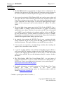
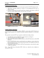
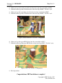
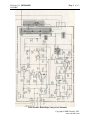
Cinelabs HV-2000 Flyback Installation
Guide for the Wells-Gardner K6100
WARNING: CRT display monitors can produce lethal
voltages. Refer servicing to qualified service personnel.
PLEASE NOTE: This product is intended to be installed following the guidelines contained in
this document, by qualified service personnel. The manufacturer and distributors of this product
will not be held liable for any damage resulting from this product’s use. If you are uncomfortable
with this, you may return the product within seven (7) days, for a full refund.
Revision 1.0
June 3, 2007
Revision 1.0 : RELEASED
6/18/2007
Page 2 of 11
If properly installed by a qualified service person, this product will be warranted for a period of
one year. This period starts on the date of receipt of product, if ordered directly from Cinelabs,
or, from the purchase date on the original receipt, if purchased through an authorized distributor.
Should you ever have to use this warranty, the distributor you purchased your Flyback from will
repair or replace, at their option, the original part. The distributor’s and Cinelabs’ liability is
limited to replacement of the part, and neither party will be responsible for any damages
incidental or consequential to your game or person. This warranty does not cover “abuse”
(physical, environmental, or electrical), and is only valid for parts installed in a genuine WellsGardner High-Voltage unit. Please contact Cinelabs in advance, regarding warranty terms for
components used in third party/aftermarket HV Boards. Please note, the warranty is void if the
Cinelabs sticker is removed.
Terms: By installing this part, you agree to take full responsibility for any damage caused to your
game and/or person, you may incur, due to lack of experience or expertise, lack of having the
correct tools, etc. You agree to read the complete installation manual, prior to installing the part,
and complying with all safety advisements and warnings.
Revision History:
Rev.
0.1
0.2
0.4
0.5
Date
12/10/2006
12/14/2006
12/18/2006
1/22/2007
Author
Shostak
Shostak
Shostak
Shostak
1.0
6/03/2007
Shostak
Comments
Initial Draft
Major Editing
Incorporated Review Feedback
Added revision history, Warranty, T&Cs, comments and
corrections note, and latest revision link
Formal Release
The most recent revision of this document can be found at:
http://www.cinelabs.com/docs/WG_Install.pdf
Please send corrections or comments to: [email protected]
This guide is intended to assist in the replacement of the Flyback Transformer (“FBT”) of WellsGardner 6100 and 6400 series color X-Y Vector monitors, when it has been determined the FBT
is defective. This guide is not intended to explain how to troubleshoot or diagnose these
monitors. Use the original Wells-Gardner monitor service manual for information on
troubleshooting, parts replacement and proper adjustment and alignment of the monitor.
Copyright © 2006 Cinelabs, LLC
www.cinelabs.com
Revision 1.0 : RELEASED
6/18/2007
Page 3 of 11
Be sure to perform the high-voltage adjustment and if you are using a P329 HV PCB, perform
the high-voltage shutdown adjustment.
Be sure to read this entire document *before* working on your 6100 monitor.
CRT displays are dangerous and potentially lethal. There is risk of physical
injury from the glass CRT and danger of electrocution from high-voltage.
We advise always wearing safety glasses when working on CRT displays, as well
as keeping one hand behind your back when working on a CRT display, energized
or not.
Remember, CRT picture tubes can store a High-Voltage charge for extended
periods of time. Always be sure to discharge the CRT prior to FBT replacement
and follow ALL industry safety practices and procedures, regardless of how
long the display has been turned off. Never make any assumptions.
Be sure to perform the high-voltage adjustment and perform the high-voltage
safety shutdown adjustment.
If you are unsure of how to perform any safety related procedures, or are unsure of
how to safely perform this procedure, please contact a trained service technician to
perform the installation or return the never installed FBT, for a full refund.
Please note, there is a factory connection point on the top of the Flyback. This
terminal is only for factory use, and is to remain disconnected during normal
operation.
Copyright © 2006 Cinelabs, LLC
www.cinelabs.com
Revision 1.0 : RELEASED
6/18/2007
Page 4 of 11
Helpful Hints:
The HV-2000 flyback kit can optionally be shipped with an “enhancement” kit,
intended to help protect the WG high voltage unit from more extensive damage in
the event of a failure of a critical component. See page 9 for more information.
Over years of servicing the Wells-Gardner 6100, one issue has come up time and
time again. This issue is the installation of incorrect parts, frequently resistors and
Zener diodes, during previous repairs. This often results in subtle problems such
as poor regulation, low voltage output, or excessively high high-voltage output.
Always use the correct parts, and be on the lookout for “artifacts” of creative
repairs.
The typical high-voltage output range for the Wells-Gardner 6100 HV Cage is
roughly 15,000V to 22,000V. Flyback Transformers are capable of producing
significantly more voltage. Therefore, if your notice your HV Cage is generating
over 24,000V, it may be indicative of a regulation problem. At least one HV Cage
has been encountered by Cinelabs which was producing in excess of 27,000V.
This problem was ultimately traced to resistors of the wrong value having been
installed in the regulator circuit during a previous repair.
On principle, after repairing the WG HV Cage, be sure to perform the highvoltage adjustment. If you are using a P329 HV PCB, perform the high-voltage
shutdown adjustment. This applies whether or not the FBT has been replaced.
If at any point you experience a no high-voltage condition after installing this
upgrade, always remember to check the fuses.
A “cap kit” can help eliminate some problems with the HV Cage. In addition, a
well respected RGVAC member recommends using 470uF High-Frequency caps
in place of the original C901 and C902, as well as using a 7 watt wire-wound
resistor in place of R901. We pass this information along as a courtesy, but have
not tried it.
The “Wells-Gardner 6100 Color Vector Monitor FAQ” is a good source of
background information, as well as specific information on troubleshooting the
WG HV unit. Copies are available across the internet, at sites such as Ionpool:
http://ionpool.net/arcade/tech/6100_faq.pdf
For further information on trouble-shooting the Wells-Gardner Color Vector
monitor,
the
reader
is
directed
to
the
Usenet
group
Rec.Games.Video.Arcade.Collecting, and to the Vectorlist archives, which are
located at http://www.vectorlist.org.
Cinelabs is a proud sponsor of the Vectorlist. :-)
Copyright © 2006 Cinelabs, LLC
www.cinelabs.com
Revision 1.0 : RELEASED
6/18/2007
Page 5 of 11
HV Cage Removal:
1. Determine FBT is defective.
2. Discharge any residual energy from the CRT, following industry standard CRT
discharge procedures.
3. Disconnect the FBT anode cap from the CRT, following industry standard procedures
(we recommend, at minimum, keeping one hand behind your back).
4. Momentarily short the anode cap to the chassis, to ensure the FBT is discharged.
5. Disconnect Focus and Screen connector (3 pin Amp connector) from HV unit.
6. Disconnect power connector (8 position red Molex connector) from HV unit.
7. Remove screws.
8. Remove HV Cage from monitor.
Flyback Replacement:
1.
2.
3.
4.
Disconnect and remove the Focus Assembly from the HV Cage.
Be sure to save the plastic insulator, as this part will be reused.
Unsolder and remove the original FBT from the HV Cage.
Remove the original plastic grommet from the high-voltage wire between the Flyback
and Focus Assembly, as this part will be reused.
5. On the back side of the new Focus Assembly, carefully remove the two plastic alignment
tabs. DO NOT CUT/REMOVE ANY METAL. We’ve found an X-Acto knife works
very well.
Figure 1: Plastic Alignment Tabs
Note: Failure to remove the plastic alignment tabs in step 5 will prevent the Focus Assembly
from lying as closely as possible against the back of the HV Cage.
Copyright © 2006 Cinelabs, LLC
www.cinelabs.com
Revision 1.0 : RELEASED
6/18/2007
Page 6 of 11
6. If installing in a P329 HV Cage, read additional P329 steps NOW (see page 7).
7. Install and solder the new replacement Flyback transformer in the HV Cage. Note: To
make it easier to adjust the pins on the new FBT, it can be temporarily installed from the
bottom of the PCB, as an alignment guide. Once the pins are properly aligned with the
holes in the PCB, install the FBT from the top of the PCB and solder in place.
8. Solder the ground wire to the ground lug on the Focus Assembly (same lug as on the
original Focus Assembly).
9. Attach the Focus Assembly to the HV Cage using the original screws and nuts, being
sure to install the plastic insulator removed from the original Focus Assembly. Do
not tighten the nuts at this time.
10. Attach the Focus and Screen wires to the Focus Assembly, being sure the connectors and
boots are fully seated.
11. Tighten the Focus Assembly screws and nuts. Note: The ground lug can contact the metal
chassis, provided this is NOT a P329 HV Cage (with HV Shutdown adjustment). For
P329 installation, see additional steps on page 7.
12. Install the grommet removed in step 4, on the red HV wire between the new Flyback and
the Focus Assembly. Then press the grommet into the HV Cage (where it was originally
removed from).
13. Reassemble monitor in reverse order of disassembly.
Did you install the plastic insulator behind the Focus Assembly?
We recommend installing the additional HV protection detailed on page 9.
HV Adjustment:
The following adjustment should be performed with no video signal applied to the monitor.
DO NOT attempt to adjust the HV using the Video B+ supply as a reference, as many factors
influence this voltage, and it will most likely result in a significant HV error.
1. With power OFF
2. Center the High Voltage control pot (R918).
3. Connect a high-voltage probe to the monitor (following the probe’s manufactures’
instructions).
4. Apply power to monitor and allow it to warm up for at least 15 minutes.
5. Adjust the HV output control pot (R918) for a reading of 19.5KV.
6. Inject a video signal into the monitor.
7. Adjust the Screen and Focus controls to taste.
Copyright © 2006 Cinelabs, LLC
www.cinelabs.com
Revision 1.0 : RELEASED
6/18/2007
Page 7 of 11
P329 Specific Installation Steps:
These additional steps must be followed to ensure proper operation of the HV shutdown circuit:
1. Check Focus Assembly ground lug to ensure it is not contacting the HV Cage (i.e.
shorted to ground).
2. If required, elongate the screw holes in the Focus Assembly (and insulator), which will
allow you to shift it slightly upwards, and ensure there are no shorts.
GOOD: No Shorts to Chassis
BAD: FA Shorted to Chassis
P329 HV Shutdown Adjustment:
If your HV board is a P329 (WG part number 85X0155), you must adjust the HV Shutdown set
point, for proper operation. We recommend setting the shutdown adjustment to a conservative
23KV.
This procedure assumes the HV Cage is properly assembled and working correctly.
1. Set the HV Trip adjustment (R930) fully counter-clockwise (see Figure 2).
2. Adjust the HV output control (R918) to 23KV1.
3. Rotate the HV Trip adjustment (R930) clockwise, until the HV shuts down, and the LED
illuminates.
4. If you rotate R930 fully clockwise and the unit has not shutdown, you have fault in the
HV cage which needs to be corrected before this procedure can be completed and the unit
returned to normal operation.
5. Center the HV output control (R918) (NOT the Trip adjustment), and perform the regular
19.5KV HV adjustment.
Note1 – Not all HV Cages will produce 23KV. In this case, adjust the unit to shutdown at
maximum HV output.
Copyright © 2006 Cinelabs, LLC
www.cinelabs.com
Revision 1.0 : RELEASED
6/18/2007
Page 8 of 11
Figure 2: R930 HV Trip Adjustment
Copyright © 2006 Cinelabs, LLC
www.cinelabs.com
Revision 1.0 : RELEASED
6/18/2007
Page 9 of 11
Background on WG Over-Current Protection Components:
Over the course of the development of the new HV-2000, many failed HV cages were repaired
for use in the project. Frequently, they were charred to a crisp (see figure 3). Additionally, during
one of the early Alpha tests, the 25 cent NE555 timer chip failed (unrelated to the new FBT :-),
resulting in damage to the output transformer (see figure(s) 4), and rendering the board useless.
At that point, it became clear that the over-current protection in the 6100 was insufficient to
protect the HV Cage.
Figure 3:
Figure(s) 4:
This enhancement adds a simple over-current protection mechanism to the WG6100 HV Cage.
Specifically, a 630ma slow-blow fuse is installed in both the positive and negative power supply
rails and a 250ma PICO®II fuse is installed in the current source for the drive transformer, T901.
Disclaimer: This enhancement will help protect the HV Cage, but problems can and will still
occur. The intent here is to attempt to limit the damage, when a problem does occur.
These parts will be provided with the HV-2000, while supplies last. If you did not receive these
parts, you can obtain them from your “local” electronics parts supplier.
While this protection circuit provides protection on the new FBT, it also provides protection for
your step down transformer, T901, which is otherwise unprotected and actually quite vulnerable.
The over-current protection is recommended, but not required. If the protection is not added, the
HV Cage will merely continue to operate as it has for the last 25+ years. This enhancement can
also be added to HV Cages with an original WG FBT installed, to help protect those units as
well.
Installing Enhanced Protection Components:
1. Unsolder and lift one leg of the following resistors from the HV PCB:
R901
R907
R917
Copyright © 2006 Cinelabs, LLC
www.cinelabs.com
Revision 1.0 : RELEASED
6/18/2007
Page 10 of 11
2. Solder one leg of one of the provided slow-blow fuses into the vacated hole of R901.
3. Solder the other leg of the slow-blow fuse to the raised leg of R901, “Tee-Pee” style.
4. Solder one leg of the remaining slow-blow fuse into the vacated hole of R907.
5. Solder the other leg of the slow-blow fuse to the raised leg of R907, “Tee-Pee” style.
Figure 3: R901 and R907 in “Tee-Pee” Configuration
6. Solder one leg of the green PICO® fuse into the vacated hole of R917.
7. Solder the other leg of the green PICO® fuse to the raised leg of R917, “Tee-Pee” style.
Figure 4: R917 in “Tee-Pee” Configuration
8. End of procedure.
Congratulations. FBT Installation is complete!
Copyright © 2006 Cinelabs, LLC
www.cinelabs.com
Revision 1.0 : RELEASED
6/18/2007
Page 11 of 11
Wells-Gardner K6100 High-Voltage Unit Schematic
Copyright © 2006 Cinelabs, LLC
www.cinelabs.com