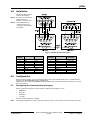
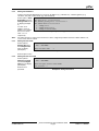
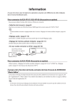
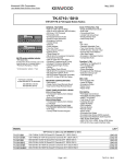
1
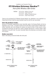
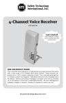
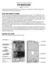
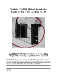
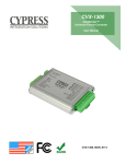
READYKEY pIPer
Serial Ethernet Unit
Installation Guide
1.0
Description
The pIPer is a unit that allows an RS-232 signal to be carried over an
Ethernet network, which makes it ideal for connecting Readykey door
controllers to a Central Network Controller (CNC) by using an existing Local
Area Network (LAN) or Wide Area Network (WAN).
For more technical information, see http://www.mutek.co.uk/piper.htm.
2.0
Modes
The pIPer unit has two modes of operation: modem (recommended) and
direct connection.
2.1
Modem Mode
In modem mode, the pIPer acts as a Hayes-compatible modem, which
allows Readykey site programming and configuration to be performed in the
same way as similar sites connected by a dial-up (PSTN) modem.
Figure 1 shows a modem mode
configuration.
Door Controller
The benefit of this arrangement
is that up to 127 sites can be
supported with one CNC. Since
this is a modem based system,
the same CNC limits (of 32 sites
with up to 8 door controllers and
95 sites with a single door
controller) apply.
Like the standard dial-up
system, the modem mode
connection is not permanent,
and there will be delays in
getting updates to the sites and
events returned from the site.
Dial-back is supported which
allows alarm events to be sent
back immediately to the CNC.
1 2
1 2
1 2
pIPer Unit
WAN
1 2
pIPer Unit
CNC
Figure 1: pIPer Modem Connection
2.2
Direct Connection Mode
Direct connection mode is used to create a permanent serial link between a CNC and a door controller. This
allows a maximum of three sites, each using a pIPer serial port, consisting of up to eight door controllers, to
be supported by one CNC.
For more information on the Central Network Controller, READYKEY K6100/K6300 CNC II Install Manual
(P/N: 46512) and the READYKEY K6100/K6300 CNC II User’s Guide (P/N: 48569).
WHEN USING pIPer IN THE DIRECT CONNECT MODE, IF THE UNIT CONNECTED TO THE CNC
LOOSES POWER, THE COMMUNICATION LINK WILL NOT BE ESTABLISHED AGAIN UNTIL POWER
FOR THE UNIT AT THE CONTROLLER IS CYCLED. IT IS STRONGLY ADVISED THAT THE POWER
FOR UNIT CONNECTED TO THE CNC BE FROM A U.P.S. OR OTHER FORM OF STANDBY POWER.
17408 v1.1 / 46833C
pIPer
Figure 2 shows three sites
connected to a CNC and, since
each pIPer unit has two serial
ports, only two devices are
needed at the CNC.
Door Controller
The advantage of a permanent
connection maintained
between the central point and
the remote sites is that
updates (i.e. changes to the
system) and events are
communicated immediately,
e.g. alarms appear at the
central PC with a minimum of
delay.
1 2
1 2
1 2
pIPer Unit
WAN
1 2
1 2
pIPer Unit
CNC
Figure 2: pIPer Direct Connection
3.0
Requirements
3.1
Hardware and Software
The pIPer works with following equipment and software:
3.2
•
MKII CNC Ver 2.34 and later.
For more information on the Central Network Controller, see READYKEY K6100/K6300 CNC II Install
Manual (P/N: 46512) and the READYKEY K6100/K6300 CNC II User’s Guide (P/N: 48569).
•
READYKEY K2100 Series Door Controllers Ver 3.37 and later.
For more information on the READYKEY K2100 Series Door Controllers, see READYKEY K2100/1100
Install Manual (P/N: 74-06964-000-B, PAC P/N: 17111) and the READYKEY K2100/1100 User Manual
(P/N: 74-07069-000-B, PAC P/N: 17117).
•
READYKEY K2200 Series Door Controllers Ver 1.05 and later.
For more information on the READYKEY K2200 Series Door Controllers, see READYKEY K2200 Series
Installation Guide (P/N: 46513) and the READYKEY K2200 User Guide (P/N: 47491).
Network
To ensure effective operation of the pIPer on a LAN or WAN, the following requirements must be fulfilled:
3.2.1
Ethernet
The pIPer units require a 10baseT twisted pair (RJ45) Ethernet connection to the local network.
Note:
3.2.2
There is no BNC (10base2) alternative and no token ring version available.
IP Address
A fixed IP address is required for each unit. DHCP or BOOTP is not supported.
Before configuring any of these devices, an IP address along with subnet mask and default gateway (or
router) should be provided by the network administrator. If the pIPer units are to operate on the same
subnet, the default gateway is not required.
3.2.3
WAN Issues
These devices use UDP as their communications protocol. On complex networks, or on links that may need
to cross firewalls, it should be verified that a UDP connection can be established between devices.
17408 v1.1 / 46833C
pIPer Serial Ethernet Unit Installation Guide
Page 2
© 2002 Radionics
pIPer
4.0
Installation
Connect the pIPer units as
shown in the Figure 3.
Note 1: All connections shown are
solder side view or
terminal connection view.
Note 2: CTS and DTR are not
connected at the door
controller as this is linked
at the CNC.
Figure 3: PC/CNC & pIPer Connections
Pin
Number
1
2
3
4
5
6
7
8
9
PC/CNC
Not connected
Red
Blue
Link to 8
Black
Not connected
Green
Link to 4
White
pIPer
Red
Blue
Black
Green
White
-
Pin
Number
1
2
3
4
5
6
7
8
9
Table 1: PC to CNC Pinouts
5.0
pIPer
Not connected
Red
White
Not connected
Black
Not connected
Link to 8
Link to 7
Not connected
Door
Controller
Receive RX
Transmit TX
Ground (0V)
-
Table 2: pIPer Pinouts
Configuration
Before the pIPer mode is set, first configure the pIPer units; to do this will require a PC, a communications
program (e.g. Tera Term Pro which is available from
http://www.vector.co.jp/authors/VA002416/teraterm.html), and a serial port connection from the PC to serial
port 2 of the pIPer.
5.1
Configuring the Communications Program
Before connecting to the pIPer ensure that the communication program is set to:
•
9600 baud.
•
No parity.
•
8 data bits.
•
1 stop bit.
No other settings need to be changed.
Note:
The cable provided that is used to connect the CNC to a pIPer, can be used to connect the pIPer to the PC.
© 2002 Radionics
pIPer Serial Ethernet Unit Installation Guide
Page 3
17408 v1.1 / 46833C
pIPer
5.2
Root Menu
PIPER - ROOT MENU
When connected, type ++++
to display the Root menu
(Example 1).
Note:
1
2
3
4
Press [S] to save changes
made before exiting this
menu.
-
Set up Link
Configure Unit
Display units on line
Display statistics
S - Save settings
ESC Quit without save
Enter selection
Example 1: pIPer Root Menu
5.3
Basic Configuration for all pIPer Units
Both the source unit (the pIPer connected to the CNC) and the destination unit (located at the door
controller) need to have the following options configured:
•
Serial Ports.
•
IP numbers (IP address, subnet mask and default gateway).
•
Name.
•
Password.
To do this:
1.
From the Root menu, select option 2 - Configure Unit.
2.
Enter the name of the unit or its IP address; if it is being configured for the first time or it has been reset
to factory defaults, enter its default name: PIPER.
3.
Enter the
password for the
unit; if it is being
configured for the
first time or it has
been reset to
factory defaults,
enter PASS as a
password.
The Configure Unit
menu is displayed
(Example 2).
Note:
Press [S] to save
changes made before
exiting this menu.
CONFIGURE UNIT 192.168.4.12
1
2
3
4
5
6
7
8
9
A
B
-
Set serial port 1 - named port1 - destination port.
Set serial port 2 - named port2 - destination port.
Feature not present (Set parallel port)
Feature not present (Set relay I/O port)
Rename Unit - DC1
Change Password
Enter IP numbers - 192.168.4.12, 192.168.4.1, 255.255.255.0
Packet send values - 100ms from last char, 256bytes, Char= none
Reset to Factory Defaults
Embedded commands - AT commands ON, Auto answer ON
Change Trigger character - +
S - Save settings
P - Return to previous menu
ESC - ROOT MENU
Enter selection -->
Example 2: pIPer Configure Unit Menu
5.3.1
Configuring Serial Ports
Select option 1 or 2 from the Configure Unit menu to display (Example 3).
The only settings that
need to be altered
are:
•
•
Option 2 - Stop
(stop bits), which
needs to be
changed to 2.
Option 5 –
Handshake,
which needs to
be changed to 6
– None (pIPer
only).
PORT CONFIGURE
Port named port1 is setup as - No handshake
9600 Baud No
Parity 2 Stop bits and 8 Data bits
Character delay none
1
2
3
4
5
6
7
8
-
Baud
Stop
Parity
Data bits
Handshake
Rename Port
8 channel receiver
Output delays
S - Save settings
P - Previous Menu
ESC Root Menu
Example 3: pIPer Port Configure Menu
Note:
Press [S] to save changes made before exiting this menu.
pIPer Serial Ethernet Unit Installation Guide
17408 v1.1 / 46833C
Page 4
© 2002 Radionics
pIPer
5.3.2
Setting the IP Address
Contact your network administrator to receive an IP address (e.g. 192.168.1.51), a default gateway (e.g.
192.168.1.254) and a subnet mask (e.g. 255.255.255.0).
Select option 7- Enter
IP Numbers from the
Configure Unit menu
to display (Example
4).
Change IP numbers
The units IP no. is 192.168.4.12
The default gateway IP no. is 192.168.4.1
The subnet mask is 255.255.255.0
1 - Change IP no.
2 - Change Router IP no.
3 - Change Local Net Mask
To enter an IP
number, router IP
number or to change
the local net mask,
enter 1, 2 or 3
respectively.
Example 4: pIPer Change IP numbers menu
Note:
Any pIPer unit that is connected to the network can be configured provided it has had a valid IP address set,
or it is on the same IP subnet.
5.3.3
Setting the Unit Name
Select option 5 Rename Unit from
the Configure Unit
menu to display
(Example 5).
ENTER NEW UNIT NAME
ESC - ROOT MENU
Enter new unit name
->
Example 5: New Unit Name
Enter the pIPer name.
5.3.4
Setting the Unit Password
Select option 6 Change Password
from the Configure
Unit menu to display
(Example 6).
CHANGE PASSWORD
Enter the new
password.
New password -->
© 2002 Radionics
ESC - ROOT MENU
Enter new pass word for unit PIPER
Example 6: Change Password
pIPer Serial Ethernet Unit Installation Guide
Page 5
17408 v1.1 / 46833C
pIPer
5.4
5.4.1
Configuring Modes
Dial-Up Connection
For this configuration, both pIPer units need to be set to accept AT commands. To enable the use of AT
commands follow the instructions in Sections 5.4.1.1 and 5.4.1.2.
5.4.1.1 Change the Trigger Character
The pIPer trigger character, (which is used to enter the command mode) by default is set to +, but since the
+ character is used by modems, it will need to be changed.
Change menu trigger character
1. Select option B Change Trigger
Current character is /
Character from the
Configure Unit menu to
Enter new trigger character -> (CR=none)
display (Example 7).
Example 7: Changing menu trigger character
2.
Note:
Type the character you want to use. It is recommended that you use the / (“forward slash”) character.
To return to the Root Menu, you must use the newly defined trigger character.
5.4.1.2 Enabling Embedded Commands
Note:
If you have not changed the trigger character, you will not be able to set AT command mode.
Embedded Commands –
1. Select option A –
Embedded Commands
1 – Change arming string
from the Configure Unit
2 – Toggle debug messages
menu to display
3 – Modem emulation – AT commands
(Example 8).
4 – Modem emulation – Turn auto answer off
The embedded commands
to be enabled depend on the
type of unit being used.
S – Save
P – Previous Menu
Example 8: Embedded Commands
5.4.1.3 Configuring the Source Unit (CNC Side)
1. Select option 3 - Modem Emulation - AT commands.
2. Select option 4 - Modem Emulation – Turn auto answer off (enabling AT commands and auto
answering, a function that the CNC does not require).
The Embedded Commands menu will now display (see Example 8).
5.4.1.4 Configuring the Destination Unit (Door Controller side)
Select option 3 - Modem Emulation - AT commands (enabling AT commands and auto answering, a
function that the door controller unit requires).
The Embedded Commands menu will now display (see Example 8).
5.4.1.5 IP Addresses as Telephone Numbers
The Telephone Number is based on the IP address of the door controller pIPer:
•
Any number in the IP address which is less than 100, is made up to 3 digits by inserting 0 (zero) on the
left-hand side, e.g. 123.32.4.32 becomes 123.032.004.032.
•
All full stops are removed from the new number, e.g. 123.032.004.032 becomes 123032004032.
•
Finally, letter P followed by the pIPers port number (1 or 2) is added to the end of the number, e.g.
123032004032 becomes 123032004032P2.
5.4.1.6 Readykey for Windows Settings
In Installer: Sites:
1. The Site Type should be set to either Modem (single door controller), or Modem Cluster (master door
controller with up to seven slaves).
2. The Baud Rate should be set to 9600.
3.
The CNC Port Number should be set to 1, 2 or 3 depending on which port the pIPer is connected.
4.
5.
Enter the required Duration, which is the maximum time the Network Master will stay on line to the site.
Enter the Dial Times required. These are the times (in 24 hour format) when the CNC will automatically
dial the controller.
Enter the Telephone Number. Refer to Section 5.4.1.5, above for more details.
6.
5.4.1.7 Door Controller Settings
1. The System Type should be set to 2.
17408 v1.1 / 46833C
pIPer Serial Ethernet Unit Installation Guide
Page 6
© 2002 Radionics
pIPer
5.4.2
2.
The Baud Rate should be set to 9600.
3.
Connect Modem should be set to Y.
4.
Dial Back should be set, if required. Option 2.
5.
The phone to be dialed should be entered (see Section 5.4.1.5, above for more details).
Direct Connection
5.4.2.1 Configuring the Source Unit (CNC Side)
1. From the Root menu, select option 1 - Set Up Link.
2. Enter the IP address of the source unit (you can enter the name but it is recommended that IP
addresses are used).
3. Enter the units password.
A menu similar to
Example 9 will be
displayed.
4.
5.
6.
7.
8.
9.
Enter the port
number of the
source unit (1 or
2).
Enter the IP
address of the
destination unit.
Enter the port
number of the
destination unit
(1 or 2).
Unit IP 192.168.4.12 named DC1. MAC no. 00201D004681
Port name --> port1 is a destination port
Port name --> port2 is a destination port
Port name --> port3 is a destination port
Digital INPUTS are not linked
V420K
Select Source Port of Link
1 - Serial port 1
2 - Serial port 2
3 - Parallel port 3
4 - Digital inputs
ESC - ESCAPE
Enter Port number
Example 9: Select Source Port of Link
Enter the timeout value.
Press [Enter] to accept the default value.
Press [S] to save this setting.
5.4.2.2 Configuring the Destination Unit (Door Controller side)
The destination unit requires no further configuration.
5.4.2.3 Configuring Readykey for Windows for Direct Connection
In Installer: Sites:
1. The Site Type should be set to either Direct RS232 (single door controller), or Direct RS232
Cluster (master door controller with up to seven slaves).
2.
The Baud Rate should be set to 9600.
3.
The CNC Port Number should be set to 1, 2 or 3 depending on the port the pIPer is connected.
5.4.2.4 Configuring the Door Controller for Direct Connection
1. The System Type should be set to 2.
2.
The Baud Rate should be set to 9600.
3.
The Connect Modem should be set to N.
© 2002 Radionics
pIPer Serial Ethernet Unit Installation Guide
Page 7
17408 v1.1 / 46833C
© 2002 Radionics, a division of Detection Systems, Inc.
PO Box 80012, Salinas, CA 93912-0012, USA
Customer Service: (800) 538-5807
17408 v1.1 / 46833C
Installation Guide
6/02
pIPer
Page 8 of 8