1
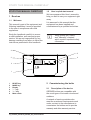
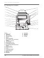
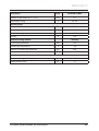
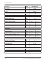
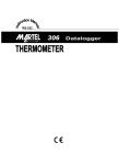
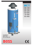
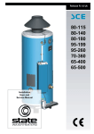
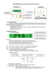
Gepard
User manual
23 MOV v.19
23 MTV v.19
Wall-hang non-condensing boiler
Power 8,5 - 23,3 kW
Flow heating HW
EN
version
CONTENTS
STUDY THIS MANUAL CAREFULLY
1
Read me ..................................................................................................... 3
1.1
1.2
2
Commissioning the boiler ........................................................................... 3
2.1
2.2
2.3
3
Storing of documents........................................................................ 5
Explanation of symbols..................................................................... 6
Safety regulations....................................................................................... 6
4.1
4.2
5
Description of the device .................................................................. 3
Commissioning the boiler ................................................................. 5
Shutting down the boiler ................................................................... 5
Manufacturer’s documentation ................................................................... 5
3.1
3.2
4
Welcome........................................................................................... 3
User’s quick start manual ................................................................. 3
What to do if you smell gas? ............................................................ 6
Safety regulations ............................................................................. 6
Warranty / Obligations ................................................................................ 7
5.1
5.2
Warranty details ................................................................................ 7
Using the device / Obligations of the manufacturer .......................... 7
6
Recycling .................................................................................................... 7
7
Packing list ................................................................................................. 8
HOW TO USE THE BOILER
8
Using the equipment .................................................................................. 9
8.1
8.2
8.3
8.4
8.5
8.6
8.7
8.8
8.9
8.10
8.11
8.12
8.13
8.14
8.15
Overview........................................................................................... 9
Turning on and off............................................................................. 9
User settings..................................................................................... 9
Regulation of the boiler… ............................................................... 10
Boiler connection parameters ..........................................................11
Connecting the boiler to the CH, HW and gas piping ......................11
Operating pressure in the heating circuit ........................................ 12
Admitting water into the heating circuit ........................................... 12
Discharging water from the boiler ................................................... 12
Expansion tank ............................................................................... 12
Safety valve .................................................................................... 13
Hooking up gas............................................................................... 13
Operating sketch of 23 MOV .......................................................... 14
Operating sketch of 23 MTV ........................................................... 15
Air and exhaust lines ...................................................................... 16
-1-
CONTENTS
8.16
8.17
Connecting the boiler to the electricity supply ................................ 21
Boiler wiring diagram ...................................................................... 23
NEED HELP?
9
Troubleshooting ........................................................................................ 24
10
Safety regulations..................................................................................... 26
11
Servicing and maintenance of the boiler .................................................. 26
11.1
11.2
11.3
Cleaning ......................................................................................... 26
Regular servicing ............................................................................ 26
Replacement parts ......................................................................... 26
12
Regulations .............................................................................................. 26
13
Converting to different fuel ....................................................................... 27
14
Contact your sales service centre ............................................................ 27
15
Available system pressure ....................................................................... 27
16
Technical parameters ............................................................................... 28
-2-
STUDY THIS MANUAL CAREFULLY
STUDY THIS MANUAL CAREFULLY
1.2
1 Read me
We have prepared this User’s manual to
help you start to use your equipment right
away.
1.1
Welcome
User’s quick start manual
It is assumed in this manual that the
equipment has been installed and
commissioned by a qualified technician.
This manual is part of the equipment and
following installation it must be provided
to the user in compliance with valid
regulations.
Study the handbook carefully to ensure
a safe installation, safe use and proper
service. We are not responsible for any
damage resulting from failure to follow the
instructions presented in this handbook.
i
Study closely the “Safety”
and “Warranty” chapters,
which contain important safety
information.
4
5
3
6
mode
2
+
–
Gepard
reset
1
1
2
3
4
5
6
RESET key
MODE key
Display
" - " key
" + " key
Main switch
2 Commissioning the boiler
2.1
Description of the device
GEPARD boilers are compatible with
the usual types of hot water circuits and
radiators.
A network of service providers who
meet the mentioned requirements work
under contract to the manufacturer to
commission the boilers and to provide
warranty and after-warranty service.
P2_GEPARD_usermanual_workbasis_EN_02-02/10-Protherm
-3-
STUDY THIS MANUAL CAREFULLY
The boiler (as well as all its optional
accessories) complies with the
requirements of European Directive
90/396/EEC on gas-fuelled appliances
and European Directive 92/42/EEC
on efficiency, the European Directive
2006/95/EC on electrical means of
operation for use in certain voltage ranges
and the European Directive 89/336/EEC
on electromagnetic compatibility.
The appliance is also approved according
to the European norms EN 677, EN 625,
EN 60335-01, EN 50165, EN 55014, EN
61000-3-2 and EN 61000-3-3.
In order to operate and handle the boiler
in accordance with the purpose for which
it is designed in actual conditions of use
(hereafter referred to only as use), it is
necessary to abide also by additional
conditions – the most essential of which
(i.e. those which must not be omitted)
are found in the following regulatory
documents:
- in the design area: STN 06 0310 and
STN 06 0830;
- in the fire safety area: STN 92 0300;
- for installation and fitting (and repairs):
STN EN 1755 or STN 38 6460, as
applicable STN 38 6462, Decree no.
48/1982 Coll. (as amended by the
later prescriptions) and the binding
occupational health regulations;
- in time of running and operation: STN 38
6405;
- in the area of discharge of combustion
gases and air inflow STN EN 483,
company material – “catalogue of dual
piping for discharge of combustion gases
and inflow of combustion air designated
for type C gas appliances, i.e. in closed
“TURBO” version.
-4-
The boiler is designated for operation
within the normal AA5/AB5 environment in
compliance with STN 33 2000-3 and STN
33 2000-5-51 (i.e. a temperature range of
5 – 40°C, temperature-dependent humidity
to a max. of 85%).
GEPARD boilers are suitable for the
conditions of zones 1, 2 and 3, in rooms
with a bath or shower and in washing
areas as set out in STN 33 2000-7-701;
they may not be installed in zone 0 (Fig.8).
Before installation in the areas mentioned,
protection against electric shocks must be
provided for according to the same norms.
The boiler complies with Ministry of Health
Decree No 13/1977 Coll., i.e. on noise, for
installation in residential and public areas.
The boilers are built to operate with
heating water, in compliance with STN 07
7401. (Above all, the water must never
be acidic, i.e. its pH must be higher than
7 and it should have minimal carbonate
hardness.)
The requirements regarding the
characteristics of domestic water are
set out in STN 83 0616 (potable water
STN 75 7111). With regards to water with
total material concentrations of calcium
and magnesium greater than 1.8 mmol/l,
further “non-chemical“ measures against
scale deposits (e.g. operation of magnetic
water treatments in combination with
settling equipment) are advisable.
Silting up of the boiler with contaminants
from the heating system or the settling of
boiler scale on these disturbances, or on
induced disturbances (e.g. silting up of the
exchanger, pump breakdowns) are not
covered by the boiler warranty.
The distance from flammable materials
(e.g. PVC, fibreboard, polyurethane,
synthetic fibres, rubber etc.) must be
P2_GEPARD_usermanual_workbasis_EN_02-02/10-Protherm
STUDY THIS MANUAL CAREFULLY
sufficient to keep the surface temperature
of these materials below 80°C.
The minimum working (unhindered) space
in close proximity to the boiler must be
such that the boiler can be worked with
easily and safely with bare hands and with
the usual hand tools; we recommend a
minimum distance of 300 mm from up and
under, 10 mm from side and a minimum of
600 mm in front of the boiler.
- CH (heating) + HW (hot water)
The GEPARD boilers supplies both central
heating and hot water for the home.
- Non-condensing boiler with exhaust
vented to a chimney
Model MOV must be fitted to a ventilation
system (chimney). The boiler comes
equipped with a safety device that shuts
off the gas feed if the chimney becomes
blocked.
- Non-condensing boiler with forced
extraction of exhaust.
The MTV model is gas model fitted with
a ventilation system for the intake of air
and the venting of exhaust. Thanks to
this ventilation system, the heater can be
installed in any space.
If the ventilator fails or if the chimney
becomes blocked, the pressure switch
shuts down the heater.
The boiler must be installed and
commissioned by a qualified technician.
This ensures proper installation and
operation in compliance with valid norms.
If any maintenance, repair or adjustments
concerning the gas are needed, a qualified
technician must be called.
PROTHERM has developed tailor-made
accessories that will help you use your
heater with maximum efficiency.
P2_GEPARD_usermanual_workbasis_EN_02-02/10-Protherm
2.2
Commissioning the boiler
Installation of the boiler and its first startup must be carried out by authorised
service personnel only!
If you wish to start the boiler after it has
been commissioned, ensure that:
- It is hooked up to the electricity supply
- All the shut-offs and valves (CH, HW,
gas) under the boiler are open
- The CH pressure is within the
recommended range of 1 – 2 bar.
2.3
Shutting down the boiler
Turn off the master switch.
If the boiler is to be shut down for an
extended time, close all the valves
(CH, HW, gas) underneath it. The shutdown must take into account the water
temperature in the boiler and the outside
temperature in the given season. If there
is a danger of frost, drain all water from
the boiler, the heating system and the hot
water piping (see the paragraph 8.9 on
page 12).
3 Manufacturer’s documentation
3.1
Storing of documents
• This manual must be stored near the
equipment to allow it to be accessed
when needed. If you should move
house, you must leave this manual
near the device in order to allow the
new owners to find it.
• To ensure safe and efficient use of
your boiler, study the instructions and
observe them carefully
We bear no responsibility for damages
resulting from failure to observe the
instructions.
-5-
STUDY THIS MANUAL CAREFULLY
3.2
Explanation of symbols
a
DANGER: Risk of injury.
e
DANGER: Risk of electric
shock.
b
PCAUTION: Risk of damage
to the equipment or its edge
parts.
i
IMPORTANT: Useful
information.
4 Safety regulations
4.1
What to do if you smell gas?
If you smell gas:
- Do not search for the leak with an open
flame.
- Do not turn on any electrical switches,
telephones or any other devices that
could spark an explosion.
- Immediately open all windows and
doors to ventilate the area.
- Shut off the flow of gas at the safety
valve.
- Alert all other persons in the building.
- Call from outside from your house the
emergency assistance services of your
gas supplier.
4.2
Safety regulations
The following regulations and safety
instructions must be observed:
• Never tamper with the safety devices.
-6-
• Do not modify the equipment or its
immediate surroundings, as this could
affect the safe use of the boiler.
• Do not under any circumstances
destroy or remove the sealing from any
of the parts.
• Never carry out alone any maintenance
or repairs to the equipment. Only
qualified technicians may work with the
equipment.
• Be careful not to allow children to play
with the boiler.
• Do not plug or obstruct the ventilation
system.
Some home “improvements” may
significantly affect the functioning of
the boiler. Before carrying out any such
intervention you must consult with the
installer.
• Do not site the equipment in excessive
dampness.
• Do not use and do not store explosive
or flammable materials (e.g. gasoline/
petrol, aerosols, thinners, chlorinebased cleaning agents, paints, glues
etc.) in the same space as the boiler.
Under certain conditions these
materials may be corrosive.
• Do not touch the equipment surfaces
- e.g. the ventilation pipes, hydraulic
connectors and so on — even after the
boiler has been turned off, as these
surfaces may be hot. Touching these
surfaces may lead to burns or scalding.
• Be prudent when using the hot water
tap. Water coming out of this tap may
be scalding.
This equipment contains metal parts
(components). In working with it and in
P2_GEPARD_usermanual_workbasis_EN_02-02/10-Protherm
STUDY THIS MANUAL CAREFULLY
cleaning it, particularly its corners, you
must be careful.
• If water leaks from the unit you must
immediately turn off the cold water
intake and the leak must be repaired by
a qualified technician.
• Do not store any objects on top of the
equipment.
5 Warranty / Obligations
5.1
Warranty details
PROTHERM’s Gepard boiler is covered
by warranty as set out by the Warranty,
Service log and other conditions listed in
the service and installation manuals.
5.2
Using the device / Obligations of
the manufacturer
The above-specified warranty is valid if:
- The equipment was installed by a
qualified technician in accordance with
the installation guidelines.
inadequate servicing or incorrect hook
up of gas or water.
- Any type of damage to a system to
which the equipment is connected.
- Any type of damage caused by
incorrect protection against freezing.
- Any type of damage or faulty set-up
caused by changes of character or
pressure of gas or water or changes in
electric voltage.
• For further information please study the
Conditions.
a
This equipment may be
installed only in countries
listed in the descriptive
plaque.
6 Recycling
Most of the boiler is comprised of
recyclable materials.
The equipment packaging must be
properly recycled.
- The equipment is used for domestic
purposes and in compliance with the
operation and maintenance instructions
of the manufacturer.
- All servicing, maintenance, repairs,
dismantling of or working with the
equipment during the warranty period
is carried out by a qualified technician
only.
- Repairs or replacement of parts during
the warranty period do not extend that
period.
The manufacturer bears no responsibility
whatsoever for any damages resulting
from:
- Any type of damage arising from
incorrect or incomplete installation,
P2_GEPARD_usermanual_workbasis_EN_02-02/10-Protherm
-7-
STUDY THIS MANUAL CAREFULLY
7 Packing list
3
2
4
5
1
6
7
9
8
Legend
1
Boiler
2
Draw bar
3
Exhaust gas diffuser (only for MTV)
4
Sealing
5
Template
6
Butt-end of water intake
7
Butt-end of outlet valve
8
Service manual
9
Warranty
-8-
P2_GEPARD_usermanual_workbasis_EN_02-02/10-Protherm
HOW TO USE THE BOILER
HOW TO USE THE BOILER
8 Using the equipment
8.1
Overview
8.2
Turning on and off
The boiler is turned on and off at the main
switch, which is located on the control
panel of the boiler.
8.2.1
Display icons
When you turn on the boiler, the display
shows the current status of the boiler:
- if the boiler is not lit (do not heat HW
eighter CH) - so called ˝stand-by˝
mode, the display shows the current
water pressure in the heating system
and tap symbol and radiator symbol on
the left side of the display
- while heating CH, the symbol flame is
light in bottom left side and the radiator
icon will begin to flash; the display
will show the real-time CH water
temperature
- while heating HW, the upper right
corner will show the flame icon and the
water tap icon will begin to flash. The
display will show the real-time water
pressure in the system
- if the pressure of the heating water
in the system falls below 0.5 bar, the
radiator symbol and current water
pressure value begins flash together. If
the pressure in the system falls furthest,
then when pressure falls below 0.3 bar
the radiator symbol and water pressure
value 0.0 bar begins flash together. In
this situation the system pressure must
be topped up by letting in water. Once
the pressure in the system reaches a
value of 0.5 bar, display shows realtime status of the boiler again
P2_GEPARD_usermanual_workbasis_EN_02-02/10-Protherm
- if pressure rises above 2.4 bar, the
real-time pressure reading begins to
flash. In this case the water pressure
in the heating system must be lowered
by draining water. Once the system
pressure falls below 2.4 bar the display
will again portray the real-time status of
the boiler.
8.3
8.3.1
User settings
Choice of heating mode
The GEPARD boiler can work in various
modes:
- heating mode - press the MODE key
once. The display will portray the realtime pressure in the system and the
radiator icon. In this mode the boiler
heats only CH water; HW heating is
locked out
- SUMMER mode - press the MODE key
twice. The display will portray the water
tap icon and the real-time pressure in
the system. In this mode, the boiler
responds only to requests for hot water;
the central heating is locked out
- VACATION mode - press the MODE
key three times. The display will show
only the real-time pressure in the
system and OFF symbol. In this mode,
both hot water and the central heating
are locked out. All the protective
functions of the boiler are active.
8.3.2
Setting the hot water
temperature
Press the (+) or (-) key, and the tap
icon will begin to flash and °C. Pressing
the (+) or (-) keys sets the desired HW
temperature anywhere in the range of 38 60°C, at one-degree increments.
-9-
HOW TO USE THE BOILER
8.3.3
Setting the temperature of the
central heating water
Press the (+) or (-) key, followed by the
MODE key, and the radiator icon and °C
will begin to flash. Pressing the (+) or (-)
keys sets the desired CH temperature
anywhere in the range of 38 - 80°C, also
at one-degree increments.
8.4
from faulty setting of the boiler or room
regulator.
8.4.3
The boiler will maintain the selected
CH temperature. Boiler operation is
interrupted (turned on and off) according
to the internal temperature in the room in
which the room regulator is located.
Regulation of the boiler
8.4.4
8.4.1
Operating the boiler without a
room regulator
In this mode the boiler will maintain the
chosen CH temperature. A room regulator
is not connected; connection terminals
have to be interconnected (supplied by the
manufacturer).
Set-up:
- Press the main On/Off switch
- Set the desired CH temperature on the
control panel
8.4.2
Operating the boiler with a
room regulator
If a room regulator is used, the CH
temperature must be restricted at the
boiler control panel to the maximum
recommended for your heating system
(to avoid damage to your system), and
which can also cover the thermal losses of
the property at low outside temperatures.
Heating of the central heating water
can then be managed by the regulator,
which will permit only that maximum CH
temperature you have set at the control
panel.
Note: In spaces with a regulator there
should be no thermostatic valves on the
radiators.
Caution: The manufacturer assumes
no responsibility for damages resulting
- 10 -
On/OFF regulator
Regulator with output
modulation function selected
The room regulator continuously regulates
the boiler output into the heating circuit
based on the indoors temperature.
8.4.5
Boiler operation with
isothermal regulation
The boiler regulates the CH temperature
based on changes in the outside
temperature. For this type of regulation
it is necessary to use a regulator with an
isothermal regulation function (Protherm
Thermolink B, Thermolink P or Thermolink
RC) and to connect it to the outside
temperature sensor.
Caution: Setting the maximum CH water
temperature on the boiler control panel
may influence the isothermal regulation.
The CH water temperature selected at
the boiler control panel is also the limiting
temperature; The room regulator setting
cannot override the heat limit temperature
set at the boiler control panel. Setting
an appropriate CH water temperature
at the boiler control panel is one way to
guard against exceeding the maximum
allowed temperatures into the heating
system (floor heating). Despite this, we
recommend placing into the heating
system a supplementary safety armature
that will guard against a harmful increase
in temperature.
Caution: The room regulator and external
sensor may be connected by authorized
service personnel only.
P2_GEPARD_usermanual_workbasis_EN_02-02/10-Protherm
HOW TO USE THE BOILER
Boiler connection parameters
8.5.1
82
65
116
65
82
Gepard 23 MOV
26
179
160
205
134
8.5
25
Ø1
742
205
8.6
410
8.5.2
The boiler connection terminals may not
be placed under undue pressure from
the piping system for the CH circuit,
the HW circuit or from the gas intake.
This assumes a precise observance
of the dimensions of the endings of all
connecting pipes, with regard to height as
well as distance from walls and separation
distances of the interconnected individual
intakes and outlets.
311
Gepard 23 MTV
Ø3
9
184
205
742
410
Connecting the boiler to the CH,
HW and gas piping
311
P2_GEPARD_usermanual_workbasis_EN_02-02/10-Protherm
The heating system circuit should be
connected to the boiler in such a way that
during repairs to the boiler the heating
water need be released only from the
boiler.
During reconstructions, in adverse building
arrangements and so on, the boiler may
be connected to the CH heating system,
the HW system and the gas inlet with
flexible elements (hoses), but only those
designated for this purpose. If flexible
elements are used, these should be as
short as possible and must be protected
from mechanical and chemical stresses
and damages. It must also be ensured
that before the end of their life cycle or
reliability in maintaining their parameters
(according to their manufacturers’ data)
they are always replaced by new ones.
- 11 -
HOW TO USE THE BOILER
Note: The boiler includes filter which is
situated below the HW flow sensor. You
have to take out the HW flow sensor with
filter to clean up the filter.
8.7
Operating pressure in the heating
circuit
The heating system (measured at the
boiler) must be filled to a hydraulic
pressure of at least 1 bar (corresponding
to a hydrostatic height of water of 10 m.)
The recommended pressure range is
between 1 - 2 bar.
8.8
Admitting water into the heating
circuit
Bringing water into the heating system
(small quantities only) can be done via the
inlet valve on the boiler.
A complete draining of water from only
the boiler or the heating circuit and repeat
filling must be carried out at inlet/outlet
valves at appropriate locations in the
heating circuit.
Discharging and filling of water into
the heating circuit and the subsequent
operations (air venting, regulating the
expansion tank) are not covered by the
boiler warranty.
If the HW in the boiler and piping is
threatened with freezing, appropriate
measures must be taken to avoid this
entirely.
Note: The release valve is located on the
right side of the boiler at the pump.
When filling the boiler the following
conditions must be observed:
- The water pressure on entry into the
boiler must always be higher than the
water pressure in the CH circuit.
- Water is drawn into the boiler strictly
in a cold state (CH temperature in the
boiler up to 30°C).
- The recommended water pressure in
the cold boiler (up to 30°C) is between
1 – 2 bar.
- The pressure in the expansion tank
is checked and if necessary adjusted
to the correct value (see technical
parameters on end of this manual).
8.9
Discharging water from the boiler
The outlet valve is designated primarily for
lowering the water pressure in the boiler
during repairs. Only a partial discharge of
water from the boiler is possible through
this outlet.
- 12 -
8.10 Expansion vessel
Before filling the CH system, check the
pressure in the expansion chamber. The
initial pressure in the expansion chamber
should be greater by 0.2 bar than the
static height of the water column of the
heating circuit.
Water may then be released into the CH
system. Filling water pressure should be
0,2 – 0,3 bar higher than the pressure in
the expansion chamber. Filling pressure is
controlled from the cold state by the gauge
on the water side after bleeding.
P2_GEPARD_usermanual_workbasis_EN_02-02/10-Protherm
HOW TO USE THE BOILER
The valve for topping up the pressure in
the expansion chamber is on the right
side.
Caution: Confirm that the expansion
chamber is sufficient for the given quantity
of water in the CH circuit (see the project
installation documentation).
8.11 Safety valve
The safety valve is located the underside
of the boiler on the left of the hydraulic
block. Draining from the safety valve
may lead (if the maximum pressure in
the system is exceeded) to the outflow
of water or the escape of steam. For
overflow that may emerge through the
safety valve, it is therefore recommended
to install a bleeder that feeds into the
sewerage system of the property.
8.12 Hooking up gas
The GEPARD version of the boiler is
designated for operation with natural gas
with a rated pressure in the piping system
of 2 kPa, for which a heating value from 9
to 10 kWh/m3 is most often specified. The
dimensions of the internal gas distribution
piping and gas meter must be adequate
to handle the other gas appliances of the
user.
Gas lines in buildings must be installed in
compliance with STN EN 1775.
Caution: It is recommended that the
gas inlet into the boiler be tightened by
fastening a union nut on the top face of
the socket through the corresponding
sealing (see the Packing list).
a
After completing the
installation of the gas piping
into the boiler the gastightness of the completed
connection must be checked
thoroughly.
Caution: Do not under any circumstances
manipulate the safety valve during the
operation of the boiler. The safety valve
furthermore may not be used for releasing
water from the boiler or the heating
system. The settling in the valve of detritus
from the heating system is not covered by
the warranty.
P2_GEPARD_usermanual_workbasis_EN_02-02/10-Protherm
- 13 -
HOW TO USE THE BOILER
8.13 Operating sketch of 23 MOV
10
11
9
12
1
8
13
14
15
7
6
5
16
4
17
3
18
2
19
1
20
A
Legend
1
Safety valve
2
Gas valve
3
HW exchanger
4
Discharge valve
5
Burner
6
Ignition electrodes
7
NTC CH water intake temperature
sensor
8
Combustion chamber
9
CH exchanger
10 Exhaust gas collector
11 Combustion thermostat
12 NTC CH return water temperature
sensor
13 Expansion tank
14 Ionising electrode
15 Pump
16 CH pressure sensor
17 3–way motor valve
18 HW flow sensor
19 HW filter
20 Inlet valve
- 14 -
B
C
A
B
C
D
E
D
E
CH outlet
HW outlet
Gas inlet
HW inlet
CH inlet
P2_GEPARD_usermanual_workbasis_EN_02-02/10-Protherm
HOW TO USE THE BOILER
8.14 Operating sketch of 23 MTV
11
10
12
9
13
8
14
15
7
16
6
5
4
17
3
18
19
2
20
1
21
A
B
Legend
1
Safety valve
2
Gas valve
3
HW exchanger
4
Discharge valve
5
Burner
6
Ignition electrodes
7
NTC CH water intake temperature sensor
8
Combustion chamber
9
CH exchanger
10 Exhaust gas collector
11 Ventilator
12 Air manostat
13 NTC CH return water temperature sensor
14 Expansion tank
15 Ionising electrode
16 Pump
17 CH pressure sensor
18 3–way motor valve
19 HW flow sensor
20 HW filter
21 Inlet valve
P2_GEPARD_usermanual_workbasis_EN_02-02/10-Protherm
C
A
B
C
D
E
D
E
CH outlet
HW outlet
Gas inlet
HW inlet
CH inlet
- 15 -
HOW TO USE THE BOILER
8.15 Air and exhaust lines
The type MOV is designed for combustion
gases to be removed and discharged into
a chimney (through a chimney inlet) with
a minimum stabilised thrust of 2 Pa. The
boiler is connected to the chimney inlet by
a flue of a diameter corresponding to the
size of the boiler’s gas exhaust outlet. It is
forbidden to place inside the combustion
gases exhaust ducting any objects which
impair the combustion gases flow (e.g.
various types of heat exchangers to utilise
their residual heat). The combustion gases
exhaust ducting is not part of the boiler
accessories.
Construction of the combustion gases
exhaust ducting as well as that of the
chimney must comply with relevant
requirements. Compliance with the
requirements specified by these standards
will prevent undesirable phenomena from
occurring, such as excessive cooling of
the combustion gases, penetration of
dampness into brickwork and fluctuations
in the chimney thrust, and thus prevent
undesirable effects on the boiler’s
functioning.
are installed where possible close to the
passage where the exhaust exits the
boiler. Breakdowns caused by leaking
condensate are not covered by the boiler
warranty.
8.15.1 Methods of air and flue gas
ducting (according to STN
EN 483) and permitted piping
lengths
If not described otherwise for the
individual following methods of placing
coaxial pipe routes and their drainages,
the piping lengths (from connection at the
boiler to the drainage) can be set as in the
following cases.
Note: One Em is considered as either a 1
m direct section or one 90° joint.
Caution: If the lengths described for
individual types are exceeded, the exhaust
diffuser (orifice) must be removed from the
ventilator drain.
The following methods of air intake and
exhaust venting are recommended for the
boiler:
The boiler takes combustion air from
the space in which it is installed. Air
must be supplied in sufficient quantity in
accordance with applicable regulations.
8.15.2 The C12 method
Venting of exhaust and drawing in of
combustion air for the MTV type is done
only through designated pipes.
Length of fume ducting (23 MTV):
The level sections of the piping slope at a
gradient sufficient to let the condensation
drain towards an outside area or
towards a receptacle designed to draw
off condensation. To achieve this, the
elbow joint may be gently bent away
from the straight section. The upright
sections of the piping are always fitted
with devices to draw off condensate. The
devices for drawing off the condensate
- 16 -
Level routes and level venting into an
open area.
- 60 / 100: min. 0.3 m (with one 90°
joint), max. 3 m (with one 90° joint).If
the total fume ducting length is more
than 0.5 m, the diffuser with a diameter
of 39 mm must be removed.
- 80 / 125: min. 0.5 m (with one 90°
joint), max. 9 m (with one 90° joint).If
the total fume ducting length is more
than 1 m, the diffuser with a diameter of
39 mm must be removed.
P2_GEPARD_usermanual_workbasis_EN_02-02/10-Protherm
HOW TO USE THE BOILER
An example of a level coaxial pipe route:
version C12 (complies with STN EN 483)
8.15.4 The C42 method
Connecting to a double shared chimney.
8.15.3 The C32 method
Vertical routes and vertical venting into an
open space.
Length of fume ducting (23 MTV):
- 60 / 100: min. 1 m (with one 90° joint),
max. 4 m (with one 90° joint). If the total
fume ducting length is more than 1.5 m,
the diffuser with a diameter of 39 mm
must be removed.
- 80 / 125: min. 1 m (with one 90° joint),
max. 10 m (with one 90° joint). If the
total fume ducting length is more than
1.5 m, the diffuser with a diameter of 39
mm must be removed.
An example of a vertical coaxial pipe
route: version C32 (complies with STN EN
483)
Double piping from independent boilers
(independent routes) can feed into shared
chimneys; the transport capacity of
the chimney is judged according to the
manufacturer’s data on the chimney. If
the pipes are set into the chimney in two
directions and vertically aligned, there
must be a vertical separation between
the outlets of at least 0.45 m. Where two
outlets vent towards each other, they
must be separated by a minimum vertical
distance of 0.6 m. The exhaust piping into
the shared double chimney never has
terminal elements — the same as with
pipes that vent into open areas!
Both components of the route — external
(air) and internal (exhaust gas) — must
safely feed into the relevant chimney duct
but not protrude so deeply that they create
blockages in the exhaust or air ducts.
Length of fume ducting (23 MTV):
- 60 / 100: min. 0.3 m (with one 90°
joint), max. 3 m (with one 90° joint). If
the total fume ducting length is more
than 0.5 m, the diffuser with a diameter
of 39 mm must be removed.
P2_GEPARD_usermanual_workbasis_EN_02-02/10-Protherm
- 17 -
HOW TO USE THE BOILER
8.15.6 The C82 method
Using piping in cases where the air is
drawn in from an open area and the
exhaust vents into a shared chimney.
Length of fume ducting (23 MTV):
8.15.5 The C52 method
- 80 / 80: min. 2 x 0.5 m, max. 2 x 18
m. If the total fume ducting length is
more than 2 x 2 m, the diffuser with a
diameter of 39 mm must be removed.
Separate double piping and venting into
different areas (with different parameters,
mainly of pressure)
For venting exhaust and bringing in air for
combustion, separate piping may be used.
The separate piping may not be routed on
opposing walls of the building.
Length of fume ducting (23 MTV):
- 80 / 80: min. 2 x 0.5 m, max. 2 x 18
m. If the total fume ducting length is
more than 2 x 2 m, the diffuser with a
diameter of 39 mm must be removed.
Air may in the same way be brought in
from an open space (or a space well
- 18 -
P2_GEPARD_usermanual_workbasis_EN_02-02/10-Protherm
HOW TO USE THE BOILER
supplied with air) and exhaust extracted
into a common chimney (or, again, into a
space with common venting of exhaust
gases). The special case of B22 also
belongs in this category. (See following
text.)
8.15.7 The B22 method
Extraction of exhaust (also in separate
piping) into an open area and intake of
combustion air from an internal space in
the building in close proximity to the boiler
(in coaxial piping with the perforation of its
outer part).
Length of fume ducting (23 MTV):
- 80 / 80: min. 2 m, max. 2 m. The
diffuser must be removed.
When drawing in air for combustion from
internal areas of the building, a sufficient
quantity of that air must be ensured. No
other appliance may be connected to the
exhaust duct (whether chimney or pipe),
and when drawing in air at least 1.2 m3 of
air/hour per kW of boiler output must be
available.
towards the boiler at a nominal gradient
of 3 percent. A device for drawing off
condensate must be placed on the piping
as close as possible to the boiler.
8.15.9 Examples of flue duct
placements according
to Appendix No 7 of the
Government Regulations of the
SR No 92/1996 Coll.
- Independent apertures in a flat wall
Independent aperture creates a zone from
the axis of the aperture of a width a = 0.5
m, radius b = 1.0 m and height c = 5.0 m.
Sketch of the zone created by an
independent aperture of an exhaust stack
If the axis of the aperture is at a distance
d > 0.3 m below the upper part of the
window frame, the zone may not extend
to the window surface. At distances d ≤
0.3 m, the protective zone of radius b may
extend to the upper part of the window.
Sketch of the zone from the axis of the
aperture of the exhaust stack sited close
to the upper part of the window
8.15.8 Piping gradient
The layout of the piping must permit
a down-gradient of the exhaust piping
P2_GEPARD_usermanual_workbasis_EN_02-02/10-Protherm
- 19 -
HOW TO USE THE BOILER
The minimum distances for double
apertures set vertically in a flat exterior
wall are:
a = 0.5 m; b = 1.0 m; c = 5.0 m, a1
depending on x as follows:
x ≥ 5.0 m, then a1 = 0.5 m,
x ≥ 4.0 m, then a1 = 0.6 m,
x ≥ 3.0 m, then a1 = 0.75 m,
x ≥ 2.0 m, then a1 = 1.0 m,
x ≥ 1.0 m, then a1 = 1.2 m,
- Dual apertures set level in a flat exterior
wall
Dual apertures set vertically in a flat
exterior wall
Distances of dual apertures set level with
each other in a flat wall are:
a = 1.5 m; g = 5.0 m; c = 5.0 m.
If g < 5 m, an intersection zone occurs,
making it necessary to maintain the total
8 m width of the zone and also increase
the “a» values proportionally on both sides
(e.g., if g = 4.0 m, then a = 2.0 m).
Dual apertures set level in a flat exterior
wall
Important warning!
The examples cited for placing exhaust
ducts can be used only in repairs or
reconstructions of properties.
- Dual apertures set vertically
- 20 -
Other cases must be approached as
set forth in Decree No 410/2003 of the
Slovak Ministry of the Environment, which
amends and supplements Decree MoE
SR No 706/2002 Coll. on Air pollution
sources, on Emission limits, on Technical
requirements and general operating
conditions, on the List of toxic substances,
on the Classification of air pollution
sources and on Requirements for ensuring
the dispersion of hazardous substances.
P2_GEPARD_usermanual_workbasis_EN_02-02/10-Protherm
HOW TO USE THE BOILER
8.15.10 Safety measures
The distance of flammable materials from
the exhaust component of the separate
piping must be enough to ensure that
the temperature at the surface of these
materials is no higher than 80°C.
Exhaust may not be vented in areas:
• where a danger of explosion is present
(as set forth in STN 33 2320)
• that are interior areas of a building
(lofts, halls, stairwells etc.)
• closeable, i.e. passages or gateways
etc.
• that descend underground (even if
these remain open to the surroundings
and free of obstructions), e.g. tunnels,
underpasses etc.
These basic injunctions for venting
exhaust must always take adequate
account of where independent air intakes
are sited.
Wall apertures for coaxial piping for
drawing in air and venting exhaust are
cut to the appropriate size (approx. 120
to 150 mm) and sealed (with building
construction methods) following the
installation. Non-flammable materials (with
Degree A of flammability according to STN
73 0823) must be used for sealing, e.g.,
masonry mortar, plaster etc. Openings in
combustible walls or roofs must be made
according to the first section of this part.
8.16 Connecting the boiler to the
electricity supply
Hooking up the boiler to the mains voltage
is done through a triple-wire plug with a
flexible cord. The socket for connecting
the boiler to the electrical network must
comply with STN 33 2000-4-46. It must
always have the protective ground (pin)
P2_GEPARD_usermanual_workbasis_EN_02-02/10-Protherm
reliably connected with the PE or PEN
wire (a combination of green and yellow
colours). The boiler must always be
connected through its main to the ground
and must always be installed in a way that
allows access to the socket and plug. The
use of a variety of “adaptors”, “extension
cords” etc. is not permitted.
Caution: The preparation of plugs
and sockets as well as room regulator
connections that extend into the interior
electrical components of the boiler must
under all circumstances be carried
only by a person with electrotechnical
qualifications as set forth in Decree No.
50/1978 Coll. In the same way, servicing
of the electrotechnical components
may be carried out only by a person
with the above-mentioned professional
qualifications. Before servicing the
electrotechnical elements the boiler must
be disconnected from the current by
pulling the mains lead from the socket!
The main body of the boiler is protected
by a tube fuse (T 2A / 250 V), which is
located on the boiler control board.
For regulating the boiler from a room
regulator, only a regulator that has a novoltage input, i.e. that does not send any
external voltage into the boiler, may be
used.
Load carrying capacity of the regulator
with a relay switch is 24V / 0.1 A.
The room regulator must be connected
to the boiler with a two-wire plug. The
recommended cross-section for the room
regulator connection (copper lead) is 1.5
mm2.
Leads for connecting the room regulator
may not be coaxial with the mains voltage
leads.
The terminal for hooking up the room
regulator with the relay switch is supplied
- 21 -
HOW TO USE THE BOILER
by the manufacturer with a connector and
is located in the frame of the boiler control
panel.
Room regulators may be connected to the
GEPARD boiler via eBUS communication.
For this type of equipment, however,
we recommend installing only Protherm
Thermolink B, Thermolink P or Thermolink
RC regulators. Only in this way can the
manufacturer guarantee the optimal
functioning of the boiler.
The room regulator leads are connected to
the terminal board of the boiler.
By means of the above-mentioned
regulators the isothermal regulation
function can be activated. All settings for
isothermal curves are carried out with the
aid of the room regulator.
Note: To activate the isothermal regulation
the external temperature sensor must
be installed. The external sensor lead is
connected to the terminal board of the
boiler.
The external sensor is placed on the
coldest wall of the property (most often the
northern wall).
Caution: The room regulator lead and the
external sensor may not be coaxial with
power cables (230 V current etc.).
- 22 -
P2_GEPARD_usermanual_workbasis_EN_02-02/10-Protherm
HOW TO USE THE BOILER
8.17 Boiler wiring diagram
5
X31
X51
X40
4
6
7
X32
8
3
9
X90
10
X30
X15
2
X2
1
X25
20 19 18 17 16 15 14 13 12 11
10 9 8 7 6 5 4 3 2 1
X17
5 4 3 2 1
1 2 3 4 5 6 7 8 9
X16
X12
FUS
X11
10 9 8 7 6
X101
1 2
10 11 12 13 14 15 16 17 18
3 4
X20
X21
X14
X13
11
X17
NTC
X2
X20
20 19 18 17 16 15 14 13 12 11
10 9 8 7 6 5 4 3 2 1
1 2 3
4 3 2 1
4 5 6
X21
1 2 3 4 5 6 7 8 9
1 2
10 11 12 13 14 15 16 17 18
3 4
4 3
1 2 3
1 2
2 1
1
D
18
17
N L
230 VAC
M
24 V Ebus
16
1
1
T
14
15
Legend
1
Regulation connector
2
Exalink connector
3
NTC solar connector
4
Alternative 24V connection
5
User interface
6
Hydraulic connector
7
Gas valve
8
Ventilator
9
Fuse
10 230 V connection
11 Pump
12 Electrodes
13 NTC CH water intake temperature
sensor
P2_GEPARD_usermanual_workbasis_EN_02-02/10-Protherm
14
15
16
17
18
19
1
1
1 2
1
T
13
12
NTC CH return water temperature
sensor
Thermal fuse
NTC CH flow sensor
NTC HW flow sensor
3–way motor valve
CH pressure sensor
- 23 -
NEED HELP?
NEED HELP?
9 Troubleshooting
This section contains all possible error
codes together with the appropriate
solutions that the USER MAY carry out to
restore the boiler to operation — corrective
measures. Other error codes MUST be
dealt with by a qualified technician.
The external sensor is placed on the
coldest wall of the property (most often the
northern wall). When displaying an error
code a telephone icon and the letter F
will flash on the display together with the
relevant error code.
During the normal course of operation
of the device the ten most recent
error alarms can be displayed by
simultaneously pressing for seven
seconds both keys for setting the CH
temperature.
Code
Description
F0
Failure of NTC CH intake water temperature sensor
F1
Failure of NTC CH water return temperature sensor
F2
Failure of NTC HW sensor
F3
Failure of NTC accumulator
F4
Disruption of NTC collector
F5
Failure of air supply sensor
F6
Failure of draw sensor
F7
Disruption of NTC HW return from solar sensor
F8
Failure of NTC accumulator sensor ground
F9
Failure of NTC exhaust hood sensor
F10
Short circuit in NTC CH intake water temperature sensor
F11
Short circuit in NTC CH return water temperature sensor
F12
Short circuit in NTC accumulator sensor ground
Short circuit in NTC CH sensor
F13
Short circuit in NTC accumulator sensor
F14
Short circuit in NTC collector sensor
F15
Short circuit in air supply sensor
F16
Short circuit in draw sensor
F17
Short circuit in NTC HW return from solar sensor
F18
Short circuit in NTC accumulator sensor ground
F19
Short circuit in NTC exhaust hood sensor
F20
Safe temperature limiter is active: Cut off due to overheating
F21
Boiler locked out – threshold values exceeded
F22
Low water in boiler – pump locked out
F23
Low water level: high temperature difference between outlet and inlet NTC
- 24 -
P2_GEPARD_usermanual_workbasis_EN_02-02/10-Protherm
NEED HELP?
Code
Description
F24
Low water level: rapid temperature rise
F25
High flow temperature
F26
Incorrect flow value from stepmotor gas valve
F27
Flame sensing error – ionisation signal contrary to closed gas valve
F28
Failure to light burner at first attempt
F29
Loss of flame during burner operation
F30
Failure of lock-out sensor
F31
Short circuit in lock-out sensor
F32
Anti-freeze protection valve is active: ventilator rotations are outside tolerance limits
F33
Anti-freeze protection valve is active: Pressure sensor is not on
Pressure sensor is not off (when the ventilator is not running)
F35
Flue system error
F36
Draft detected (chimney version only)
F37
Ventilator rpms during operation are outside tolerance limits
F38
Measured frequency limit is outside tolerance limits
F39
Error in boiler auto-detection
F41
Incorrect gas regulation
F42
Problem with coding resistor
F43
Incorrect value for boiler variant
F49
Low eBus voltage
F55
Error in CO sensor
F58
No feedback from preheater
F60
Error gas valve +
F61
Error gas valve -
F62
Error – gas valve turned off
F63
EEPROM error
F64
ADC error
F65
High electronics temperature
F66
Error in IIC collectors
F67
Flame signal from ASIC is unreliable
Detected flame input signal is outside range (0 or 5V)
F70
Incorrect DSN
F71
Flow sensor permanent failure
F72
Lengthy interval between flow sensor and NTC CH return water sensor
F73
CH pressure sensor not connected or short circuited
F74
CH pressure sensor has electrical fault (or damaged cable)
P2_GEPARD_usermanual_workbasis_EN_02-02/10-Protherm
- 25 -
NEED HELP?
Code
Description
F75
Permanent failure CH pressure sensor. No rise in pressure detected following pump
start
F76
Thermal fuse failure in primary exchanger
F80
Error in SHE entry sensor
F81
Error in charger pump
F82
Error in anode tester
F90
Not connected to APC module
F91
Error in APC module sensor
• When error codes displayed, press
RESET key. If following this measure
the equipment still does not work,
contact a qualified technician.
10 Safety regulations
Insert technical content about the safety
devices of the appliance such as frost
protection, safety valves, etc...
11 Servicing and maintenance of
the boiler
11.1 Cleaning
a
Turn off the device before
cleaning
The boiler cover may be cleaned with a
gentle liquid cleaner and damp cloth, then
wiped with a dry cloth.
i
Do not use abrasive cleaners
or solvents as these may harm
the paintwork.
11.2 Regular servicing
Regular servicing is very important in extending the lifecycle and safe and efficient
use of your device.
- 26 -
b
Incorrect or inappropriate
servicing may negatively
impact the safe operation
of the equipment and may
result in injury.
We recommend annual servicing of the
equipment.
• Always call in a qualified technician.
11.3 Replacement parts
To ensure safe operation and a lengthy
lifecycle for the product, you must use only
original parts from the manufacturer.
12 Regulations
In practice there may arise situations
in which you must take the following
unavoidable measures:
• Protect against (even the accidental)
starting up of the boiler during
inspection and work on the exhaust
gas, gas and water piping by shutting
off the electricity supply to the boiler in
ways other than by merely turning off
the boiler at the main switch (e.g. by
pulling the boiler plug from the electrical
socket),
• Always shut down the boiler when
flammable or explosive vapours are
detected (even temporarily) in the
areas from which the boiler draws in air
P2_GEPARD_usermanual_workbasis_EN_02-02/10-Protherm
NEED HELP?
for combustion (e.g. from oils for mixing
paints, the spreading and spraying of
molten materials, gas leaks etc.),
• If water must be discharged from the
boiler or from the circuit, it must not be
dangerously hot
• If water leaks from the boiler exchanger
or if the exchanger fills with ice do not
attempt to start the boiler until normal
conditions for boiler operation are
restored.
13 Converting to different fuel
The Gepard boilers are in their basic
versions designed to use natural gas as
fuel. The modifications required to switch
to a different fuel must be carried out
by an authorised technician with a valid
manufacturer’s certificate.
For conversion to propane use the
conversion kit for switching from natural
gas to propane gas. The kit contains all
necessary parts and instructions on how
to perform the conversion.
14 Contact your sales service
centre
If gas leaks, there is a failure in supply or
if you suspect the same, shut down the
boiler and gas intake and immediately
contact the gas company or service
centre.
15 Available system pressure
1
2
3
4
A
600
500
400
300
200
100
0
0
500
Legend
1
Pump at setting 1, by-pass at factory
setting
2
Pump at setting 2, by-pass at factory
setting
3
Pump at setting 1, by-pass closed
4
Pump at setting 2, by-pass closed
P2_GEPARD_usermanual_workbasis_EN_02-02/10-Protherm
1000
A
B
B
Available system pressure (mbar)
Flow through the heating system (l/h)
- 27 -
NEED HELP?
16 Technical parameters
Description
Units
GEPARD 23 MOV
Gas category
II2H3P
Distribution
B11BS
Ignition
electronic
Power / fuel
natural gas
propane
Maximum thermal consumption
kW
25,8
Minimum thermal consumption
kW
10,4
Maximum thermal output
kW
23,3
Minimum thermal output
kW
9,0
Efficiency
%
89,9
Maximum gas consumption
m3/h
2,73
Minimum gas consumption
m /h
1,10
Maximum gas consumption
kg/h
2,64
Minimum gas consumption
kg/h
1,13
3
NOx classification
3
Gas pressure
Inlet pressure
mbar
20
37
mm
5,8
4,4
Maximum pressure in discharge nozzles
mbar
11,4
27,8
Minimum pressure in discharge nozzles
mbar
2,2
5,0
mm
1,20
0,73
Membrane diameter
Discharge nozzle diameter
Heating
Maximum working pressure
bar
3
Minimum working pressure
bar
0,5
Recommended operating pressure
bar
1-2
Temperature range
°C
38 - 80
Expansion tank
l
5
mbar
3
bar
10
Minimum pressure
bar
0,5
Minimum HW flow
l/min
1,7
Maximum pressure in the expansion tank
Hot water
Maximum pressure
- 28 -
P2_GEPARD_usermanual_workbasis_EN_02-02/10-Protherm
NEED HELP?
Description
Units
GEPARD 23 MOV
Quantity of HW drawn (at ∆T 30°C)
l/min
11,1
°C
38 - 60
V/Hz
230/50
W
92
Temperature range
Electrical data
Voltage / frequency
Consumption
Electrical casings
Current
IPX4D
A
Exhaust venting method
Fume ducting diameter
0,4
chimney
mm
126
Exhaust gas temperature
°C
110
Quantity of exhaust gas produced
g/s
21,0
Noise
dB
< 50
Dimensions: height / width / depth
mm
740 / 410 / 298
kg
31
Weight without water
P2_GEPARD_usermanual_workbasis_EN_02-02/10-Protherm
- 29 -
NEED HELP?
Description
Units
GEPARD 23 MTV
Gas category
II2H3P
Distribution
C12, C32, C42, C52, C82, B22
Ignition
electronic
Power / fuel
natural gas
propane
Maximum thermal consumption
kW
25,0
Minimum thermal consumption
kW
10,7
Maximum thermal output
kW
23,3
Minimum thermal output
kW
8,5
Efficiency
%
93
Maximum gas consumption
3
m /h
2,64
Minimum gas consumption
m3/h
1,13
Maximum gas consumption
kg/h
1,9
Minimum gas consumption
kg/h
0,8
NOx classification
3
Gas pressure
Inlet pressure
Membrane diameter
mbar
20
37
mm
5,95
4,20
Maximum pressure in discharge nozzles
mbar
12,2
28,1
Minimum pressure in discharge nozzles
mbar
2,4
5,1
mm
1,20
0,73
Discharge nozzle diameter
Heating
Maximum working pressure
bar
3
Minimum working pressure
bar
0,5
Recommended operating pressure
bar
1-2
Temperature range
°C
38 - 80
l
5
mbar
3
Maximum pressure
bar
10
Minimum pressure
bar
0,5
Minimum HW flow
l/min
1,7
Expansion tank
Maximum pressure in the expansion tank
Hot water
- 30 -
P2_GEPARD_usermanual_workbasis_EN_02-02/10-Protherm
NEED HELP?
Description
Units
GEPARD 23 MTV
Quantity of HW drawn (at ∆T 30°C)
l/min
11,1
°C
38 - 60
V/Hz
230/50
W
147
Temperature range
Electrical data
Voltage / frequency
Consumption
Electrical casings
Current
IPX4D
A
Exhaust venting method
Fume ducting diameter
0,4
turbo
mm
60 / 100 , 80 / 125 , 80 / 80
Exhaust gas temperature
°C
122
Quantity of exhaust gas produced
g/s
13,4
Noise
dB
< 50
Dimensions: height / width / depth
mm
740 / 410 / 298
kg
34
Weight without water
P2_GEPARD_usermanual_workbasis_EN_02-02/10-Protherm
- 31 -
Protherm spol. s r.o.
Pplk. Pľjušťa 45
909 01 Skalica
Tel.: 034 6966 101
fax: 034 6966 111
P2_GEPARD_usem
r anua_
lworkbassi_EN_00
2-2/10
Insert the bar code
www.protherm.eu