1
CHAPTER 3
ENGINES
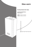
Torque Specifications ......................... 3.1
Torque Patterns - Cylinder Heads, Cylinder Base . 3.2
Torque Patterns - Crankcase ................... 3.3
Piston/Cylinder Clearance Specifications ........ 3.4
Engine Removal and Installation, Typical ........ 3.5-3.12
Disassembly, Fan Cooled Twin Cylinder Series ... 3.13-3.17
Assembly, Fan Cooled Twin Cylinder Series ...... 3.18-3.21
Disassembly, Liquid Twin Cylinder- Fuji ......... 3.22-3.25
Assembly, Liquid Twin Cylinder- Fuji ............ 3.26-3.28
Disassembly, Three Cylinder Monoblock ........ 3.29-3.33
Assembly, Three Cylinder Monoblock ........... 3.24-3.37
Disassembly, 440/500 Domestic Case Reed Twins 3.38-3.44
Assembly, 440/500 Domestic Case Reed Twins .. 3.44-3.49
Disassembly, 600/700 Domestic Case Reed Twins 3.50-3.56
Assembly, 600/700 Domestic Case Reed Twins .. 3.57-3.61
Disassembly, 700/800 Case Reed - Fuji ......... 3.62-3.64
Assembly, 700/800 Case Reed - Fuji ............ 3.65-3.68
700/800 Fuji VES System ...................... 3.69-3.72
General Inspection Procedures ................. 3.73-3.84
Cooling System Bleeding Procedures ........... 3.85
Cooling System, 500, 500 RMK Classic,Ciassic
Touring, Widetrak LX, XLT Classic, XLT Touring .. 3.86
Cooling System, 600 XC/SP, 700 XC/SP ......... 3.87
Cooling System, 600 RMK, 700 RMK, 700 SKS .. 3.88
Cooling System, 440 XCR ..................... 3.89
Cooling System, 500 XC/SP ................... 3.90
Cooling System, XLT Special ................... 3.91
Cooling System, 700/800 XCR ................. 3.92
Recoil Starter Spring Replacement .............. 3.93
Troubleshooting .............................. 3.94-3.95
ENGINES
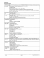
Torque Specifications
When tightening bolts, nuts, or screws, a torque pattern should be followed to ensure uniform equal tension is
applied to all fasteners. Proper torque application prevents fasteners from loosening or breaking in critical service.
It also minimizes wear and eliminates premature or needless repair costs. Following uniform torque application
sequence patterns ensures optimum performance from precision machined, close tolerance assemblies.
The most common units of torque in the English system are ft. lb. and in. lb. In the Metric system, torque is
commonly expressed in units of kg-m or Nm (Newton Meters). Multiply foot pounds by .1383 to obtain kg-m.
Move decimal point one place to the right to obtain Nm from kg-m.
Cylinder Head*
Engine
Fan Cooled
Twin
Cylinder
EC50PL
EC58PL*
EC70PL
EC79PL
18-19 ft. lbs.
(2.5-2.65 kgm)
SN44**
SN50**
20-24 ft.lbs.
(2.9- 3.3 kgm)
20-24 ft. lbs.
(2.8 - 3.3 kgm)
SN60**
SN70**
8mm
17-20 ft. lbs.
(2.4-2.8 kgm)
10 mm
24-26 ft. lbs.
(3.3-3.6 kgm)
Flywheel
Cylinder
Base Nuts
24-28 ft. lbs.
(3.3-3.9 kgm)
Crankcase
8mm
17-18ft.lbs.
(2.2-2.3 kgm)
Crankcase
10mm
23-25 ft. lbs.
(3.2-3.5 kgm)
60-65 ft. lbs.
(8.3-9.0 kgm)
24-28 ft. lbs.
(3.3-3.9 kgm)
17-18 ft. lbs.
(2.2-2.3 kgm)
23-25 ft. lbs.
(3.2-3.5 kgm)
60-65 ft. lbs.
(8.3-9.0 kgm)
30-34 ft.lbs
(4.1-4.7 kg-m)
30-34 ft.lbs
(4.2-4.7 kg-m)
20-24 ft.lbs.
(2.8 - 3.3 kgm)
26-30 Ft lbs
20-24 ft.lbs.
(2.8 - 3.3 kgm) (3.6-4.15 kgm)
90ft. lbs.
(12.4 kgm)
55 ft. lbs.
(7.4 kgm)
* Use high end of torque range on EC58PL
**Torque head bolts prior to torquing cylinder base nuts .. Apply loctite""" 242.
All 6mm Crankcase Bolts . . . . . 108 in. lbs. (1.24 kg-m)
All7/16-14 Engine Mount Strap Bolts ..... 44-48 ft. lbs. (6.0-6.63 kg-m)
Polaris Industries Inc.
3.1
10/98
ENGINES
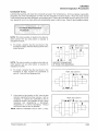
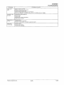
Torque Patterns - Cylinder Heads, Cylinder Base
0
CYLINDER HEAD- 5 STUD
G)
0
CYLINDER HEAD
Domestic Twins 500 I 600 I 700
CYLINDER HEAD- 6 STUD
@
@)
@
® ®cvGfDcvG:{iV@
@@0000@®@
CYLINDER HEAD - EC58PL
000 ®
80
0
000 ®
CYLINDER HEAD- EC45150PL
G)@
00 0PTO G)
G) G)
@
@ SIDE
0G) G) @)
0
CYL. BASE- 5001600/700 Twins
10/98
Cylinder Head - domestic 440
3.2
0
0
0
MAG
SIDE
0
Fuji Liquid Twins
Cylinder Base
Polaris Industries Inc.
ENGINES
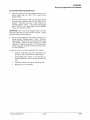
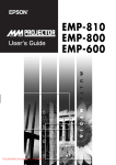
Torque Patterns - Crankcase
0
@
0
0
(j)
@
00 ®
0 0 @
@
®®CV%0®8 ®®
®
CRANKCASE-3CYLINDER
CRANKCASE- TWIN CYLINDER - Fuji
0
0
@
CRANKCASEGOO /700 DOMESTIC TWINS
Polaris Industries Inc.
f11\ @
00G)G)(j)~@
@
3.3
0
CD 0
G) ®
0
®
@@
@@
CRANKCASE - 440 I 500 Domestic Twins
10/98
ENGINES
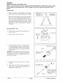
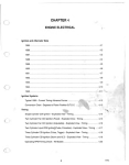
Piston/Cylinder Clearance Specifications
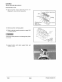
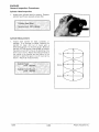
Piston Measurement
Whenever cylinders are honed or bore clearance is
checked, it is important to measure piston diameter
properly to arrive at its major dimension. Measurements
should be taken with piston at room temperature, and at
right angles to the pin as shown. Determine the largest
diameter within this area and refer to the chart below for
clearance specifications.
Cylinder bore must be straight and concentric. Refer to
honing information outlined in this chapter for specific
procedures. Refer to the specifications section in chapter
1 for Target Clearance when re-boring cylinder, or Service
Limit specifications (to determine if piston requires
replacement.
0
FUJI ENGINES- Measure 1/2" (12.7mm) up
from bottom of skirt
DOMESTIC ENGINES - Measure 3/8"
(1 O.Omm) up from bottom of skirt
Piston to Cylinder Clearance
Refer to specifications in chapter 1 for specific models.
Piston Ring Installed Gap
Refer to specifications in chapter 1 for specific models.
Important! Always verify piston to cylinder clearance and piston ring installed gap prior to
assembling an engine.
10/98
3.4
Polaris Industries Inc.
ENGINES
Engine Removal
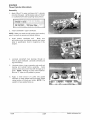
Engine Removal, Typical
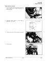
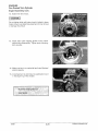
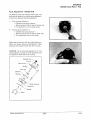
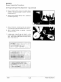
1. On some models, it may be necessary to remove the
hood for earier access to engine components or to
prevent damage.
2.
Disconnect battery ground
applicable). Shut off fuel.
H
from battery (if
Ground Cable
3.
Remove fuel pump or COl from airbox if applicable.
4.
Remove airbox.
Polaris Industries Inc.
3.5
10/98
ENGINES
Engine Removal
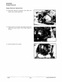
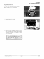
Engine Removal, Typical-Cont.
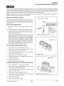
5.
Free recoil rope from chassis.
NOTE: Be sure to tie a knot in recoil rope upon removal
so rope doesn't wind up into recoil housing.
6.
Loosen clamps at carburetor mounting flange. Pull
carbs from adaptors and secure out of the way. Note
routing of all cables and hoses for reassembly.
7.
Disconnect oil pump control cable.
8.
Disconnect and plug oil supply line.
TIP: A bolt or spare water trap plug can be used to plug
the oil line from the oil reservoir.
10/98
3.6
Polaris Industries Inc.
ENGINES
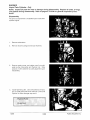
Engine Removal
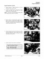
Engine Removal, Typical-Cont.
9.
Remove drive belt.
NOTE: If drive clutch removal is necessary, it may be
done at this time. Refer to Chapter 5, clutches.
10. Remove exhaust system.
NOTE: On triple pipe models, mark pipe location to simplify reassembly.
11. Disconnect coolant supply hoses as necessary at the
most convenient location on liquid cooled models.
Drain coolant into suitable container.
Polaris Industries Inc.
3.7
10/98
ENGINES
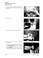
Engine Removal
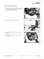
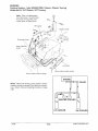
Engine Removal, Typical-Cont.
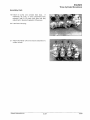
12. Disconnect electrical connections from stator and
starter motor (where applicable).
13. Remove two front and two rear engine mount bolts
(nuts) that secure engine mount plate (straps) to
chassis.
14. Remove engine from chassis.
10/98
3.8
Polaris Industries Inc.
ENGINES
Engine Installation
Engine Installation, Typical
1.
Prepare chassis for engine installation by moving
hoses and wiring out of the way.
2.
If model is equipped with a torque stop, loosen
locking screw and turn torque stop in to gain
clearance when installing engine.
NOTE: Torque stop must be adjusted properly after
clutch alignment (see chapter 5, clutches)
3.
Check condition of bonded rubber engine mounts.
Be sure mounts are tight before installing engine.
With engine mounting plate or mount straps installed
on engine, set engine on rubber mounts and loosely
install mounting bolts and nuts.
4.
Install drive belt (and clutch if removed) and check
clutch offset/alignment. Adjust torque stop (where
applicable). Refer to chapter 5, clutches, for torque
stop adjustment procedure.
5.
Tighten engine mounting bolts to specification.
Engine Mounting Bolt TorqueFront- 28 Ft lbs (6.67 kgm)
Rear- 28 Ft lbs (6.67 kgm)
Polaris Industries Inc.
3.9
10/98
ENGINES
Engine Installation
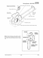
Engine Installation, Typical-Cont.
6.
Apply a light film of Polaris dielectric grease to all
connections. Connect all stator connections and
temperature switch.
Dielectric grease-
PN 2871329- 1/4 oz.
7.
Connect oil supply line to oil pump. Bleed oil pump by
opening bleed screw until oil flows steadily. Tighten
bleed screw securely. Install throttle cable to oil
pump and check adjustment. Refer to General
Inspection Procedures in this chapter for oil pump
adjustment procedure.
8.
Install carburetors and tighten clamps. Make sure
hoses and cables are routed correctly.
9.
Connect oil lines to carburetors
10/98
3.10
Polaris Industries Inc.
ENGINES
Engine Installation
Engine Installation, Typical-Cont.
10. Install coolant hoses where applicable. Make sure
hoses are routed properly and hose clamps are
positioned and tightened securely.
11. Route and install recoil rope to chassis.
12. Install starter and starter cables (electric star
models).
13. Install exhaust
disassembly.
Polaris Industries Inc.
system
in
reverse
order
o
3.11
10/98
ENGINES
Engine Installation
Engine Installation, Typical-Cont.
14. Install hood if previously removed.
15. Install airbox.
16. Secure fuel pump and CDI box.
17. Fill cooling system (liquid models) with Polaris
Premium Antifreeze 60/40 premix.
Polaris Premium Antifreeze
60/40 premix
Quart PN 2871534
Gallon PN 2871323
18. Add a full tank of premix fuel (40:1) to fuel tank.
19. Start engine and check operation. Bleed cooling
system on liquid models. See Cooling System
Bleeding Procedures in this chapter.
10/98
3.12
Polaris Industries Inc.
ENGINES
Fan Cooled Twin Cylinder
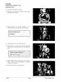
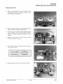
NOTE: Inspect all parts for wear or damage during disassembly. Replace all seals, 0-rings,
and gaskets during disassembly. Refer to pages 3.73-3.84 for general inspection procedures.
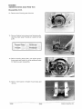
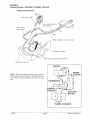
Engine Disassembly
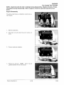
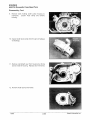
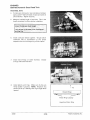
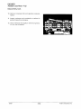
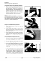
The photo at right shows a complete fan cooled twin cylinder engine.
1.
Remove carburetors.
2.
Disconnect oil pump feed lines and remove oil
pump.
3.
Remove carburetor adaptors.
4.
Remove air shrouds. NOTE: There may be
gaskets between shroud and cylinder.
Polaris Industries Inc.
3.13
10/98
ENGINES
Fan Cooled Twin Cylinder
Engine Disassembly, Cont.
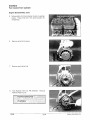
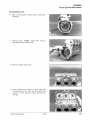
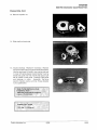
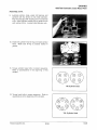
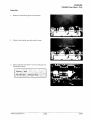
5.
Note position of shroud retainer mounts on cylinder
heads. These must be in the same position for
reassembly.
6.
Remove recoil fan housing.
7.
Remove recoil drive hub.
8.
Hold flywheel with tool PN 8700229.
flywheel retaining nut.
Remove
Flywheel Holding Tool
PN 8700229
10/98
3.14
Polaris Industries Inc.
ENGINES
Fan Cooled Twin Cylinder
Engine Disassembly, Cont.
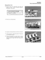
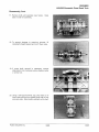
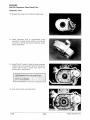
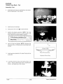
9.
Using flywheel puller, remove flywheel. Use all
available puller bolt holes on flywheel. Do not install
puller bolts more than 5/16" (7mm) into flywheel
threads or stator damage may result.
Flywheel Puller
PN 2871043
10. Mark stator plate and crankcase for reference upon
reassembly. Remove stator plate.
11. Remove two bolts securing inner and upper shroud.
Remove upper shroud.
12. Loosen and remove all bolts securing cylinder
heads to cylinder. Remove heads.
Polaris Industries Inc.
3.15
10/98
ENGINES
Fan Cooled Twin Cylinder
Engine Disassembly, Cont.
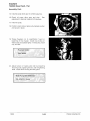
13. Remove cylinder base nuts and cylinders. NOTE:
Refer to General Inspection Procedures for cylinder
inspection.
14. Support piston to prevent damage. Remove piston
c-clip.
15. Remove piston pin and remove pistons. Refer to
General Inspection Procedures in this chapter.
Piston Pin Puller
PN 2870386
16. Remove engine mount plate or straps and remove
all crankcase bolts.
10/98
3.16
Polaris Industries Inc.
ENGINES
Fan Cooled Twin Cylinder
Engine Disassembly, Cont.
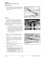
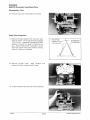
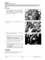
17. Separate crankcase halves.
18. Measure connecting rod side clearance. Refer to
General Inspection section for measurement
procedure.
Connecting Rod Side Clearance
.012"- .016 (.30- .40 mm)
19. Refer to General Inspection section for crankshaft
inspection procedure.
Polaris Industries Inc.
3.17
10/98
ENGINES
Fan Cooled Twin Cylinder
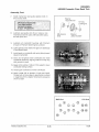
Engine Assembly
1.
Clean all engine components thoroughly in a
solvent tank. Blow dry with compressed air.
2.
Apply 3-Bond™ sealer to top half of crankcase.
Lubricate oil pump drive gear.
3-Bond
TM
1215
PN 2871557
120 Gram Tube
3.
Lightly grease seals and install on crankshaft on
crankshaft with lip (spring) facing inward toward
crankshaft. Place crankshaft in upper crankcase
half. Make sure seal and PTO bearing retainer fit
properly into grooves.
4.
Install bottom crankcase half and insert crankcase
bolts. Torque to specification in proper sequence
shown in beginning of this chapter. Lubricate
crankshaft bearings though oil holes in upper
crankcase.
5.
Install pistons with arrow (.....) on piston facing
flywheel. Install C-clips securely in piston groove.
6.
Lubricate rings and pistons with two stroke oil.
Install rings with letter, mark, or beveled side facing
upward.
7.
Install base gasket with adhesive sealant strip
facing up (if applicable).
10/98
3.18
Polaris Industries Inc.
ENGINES
Fan Cooled Twin Cylinder
Engine Assembly, Cont.
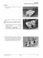
8.
Lubricate cylinder with two stroke oil and install onto
piston while compressing piston rings by hand. Be
sure ring end gap is centered over locating pin or
ring damage may occur. NOTE: Use a piston
support block to help hold piston and prevent piston
damage during assembly.
Piston Support Block
PN 2870390
9.
Torque cylinder base bolts to specification found in
the beginning of this chapter.
1 0. Install head gasket with wide side of fire ring facing
down (narrow side up).
11. Install cylinder heads and torque head bolts to
specification found in the beginning of this chapter.
NOTE: Make sure threaded head nuts are in the
proper position for shroud mounting. See "x" in
photo at right.
Polaris Industries Inc.
3.19
10/98
ENGINES
Fan Cooled Twin Cylinder
Engine Assembly, Cont.
12. Install inner fan shroud.
Do not tighten bolts until outer shroud is bolted in place.
Outer shroud must determine placement of inner shroud,
or damage may result.
13. Install stator plate aligning ignition timing marks
made during disassembly. Tighten stator mounting
bolts securely.
14. Make sure key is on crankshaft and install flywheel
aligning keyway.
15. Install flywheel nut and torque to specification found
in the beginning of this chapter.
Flywheel Holding WrenchPN 8700229
10/98
3.20
Polaris Industries Inc.
ENGINES
Fan Cooled Twin Cylinder
Engine Assembly, Cont.
16. Install recoil starter hub and recoil housing.
NOTE: Tighten two inner shroud bolts.
17. Reassemble cooling shroud.
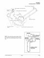
18. Install oil pump. If crankcase, oil pump, or pump
drive components were replaced, refer to General
Inspection Procedures in this chapter to inspect
drive gear end play.
Oil Pump Mounting Screw Torque:
48-72 in.lbs. (.55- .83 kg-m)
Polaris Industries Inc.
3.21
10/98
ENGINES
Liquid Twin Cylinder - Fuji
NOTE: Inspect all parts for wear or damage during disassembly. Replace all seals, 0-rings,
and gaskets during disassembly. Refer to pages 3.73-3.84 for general inspection procedures.
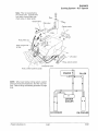
Disassembly
The photo at right shows a complete liquid cooled twin
cylinder engine.
1.
Remove carburetors.
2.
Remove recoil housing and exhaust manifold.
3.
Remove water pump, and starter recoil cup with
water pump drive pulley and flywheel nut. Note
position of shim washers for pulley alignment upon
reassembly.
4.
Install flywheel puller. Use all flywheel bolt holes.
Do no install puller bolts more that 5/16" (7mm) into
flywheel or stator damage may result.
Flywheel Puller
PN 2871043
10/98
3.22
Polaris Industries Inc.
ENGINES
Liquid Twin Cylinder - Fuji
Disassembly, Cont.
5.
Mark stator plate and crankcase for reference when
reassembling the engine.
6.
Using an impact screwdriver, remove stator screws.
7.
Remove oil pump, oil pump feed lines, and banjo
bolts from cylinder.
Clean and inspect all
components.
8.
Remove cylinder head.
Polaris Industries Inc.
3.23
10/98
ENGINES
Liquid Twin Cylinder - Fuji
Disassembly, Cont.
9.
Remove head gasket. Note position of head gasket
inlet and outlet hole sizes for reference during
reassembly.
10. Remove cylinder.
11. Remove C-clip retainers from piston as shown.
12. Using piston pin puller, remove piston pin from
piston as shown.
Piston Pin Puller
PN 2870386
10/98
3.24
Polaris Industries Inc.
ENGINES
Liquid Twin Cylinder - Fuji
Disassembly, Cont.
13. Remove crankcase bolts.
NOTE: Refer to General Inspection Procedures on
pages 3.73-3.84 for engine component inspection (i.e.
crankshaft and crankcase inspection, piston clearance,
oil pump drive gear end play etc.).
Polaris Industries Inc.
3.25
10/98
ENGINES
Liquid Twin Cylinder- Fuji
Assembly
Prior to assembly, refer to page 3.81 and check ring end gap and piston to cylinder clearance.
1.
Grease crankshaft end seals and oil pump drive
gear area as shown. Seals should be installed with
spring and lip facing inward toward crankshaft.
2.
Turn bearing until anti-rotation pins are positioned in
the proper location.
3.
Apply 3-Bond™ sealant to crankcase halves.
3-Bond
TM
1215
PN 2871557
120 Gram Tube
4.
Torque crankcase bolts following
sequence
outlined in beginning of this chapter. Lubricate
crankshaft main bearings through access holes.
5.
Install pistons with "F" mark or arrow (.....) toward
flywheel.
6.
Install C-clip using installation tool PN 2870773.
7.
Install new base gasket.
8.
Lubricate rings and pistons with two stroke oil.
Install rings with letter, mark, or beveled side facing
upward.
10/98
3.26
Polaris Industries Inc.
ENGINES
Liquid Twin Cylinder- Fuji
Assembly, Cont.
9.
Lubricate rings and cylinder with Premium 2 Cycle
Lubricant and compress rings with fingers, aligning
end gaps with locating pins. Install cylinder with a
gentle front-to-back rocking motion, being careful
not to damage rings. Install cylinder base nuts and
tighten to correct specifications found in the
beginning of this chapter
10. Install head gasket. Note proper position of gasket,
"V" notch forward, small intake hole on right (mag)
side, large hole on left (PTO) side.
11. Install cylinder head and torque cylinder head nuts
following torque specs and pattern sequence in the
beginning of this chapter.
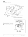
12. Before installing oil pump drive gear, refer to end
play adjustment in General Inspection Procedures.
13. Install oil pump in the sequence shown in photo at
right.
Polaris Industries Inc.
3.27
10/98
ENGINES
Liquid Twin Cylinder- Fuji
Assembly, Cont.
14. Connect oil feed lines to cylinder.
15. Align stator as previously marked on stator plate
and secure with screws.
16. Install flywheel and torque flywheel nut to
specification found in beginning of this chapter.
Flywheel Holding Tool PN 8700229
17. Install water pump and recoil starter cup.
18. Adjust tension on water pump belt by loosening
mounting bolts, applying tension, and re-tightening
bolts.
Water Pump Belt Deflection -
1/8- 3/16"(.3- .4 em)
19. Install recoil housing, carburetors, and oil pump
cable. Refer to oil pump bleeding in General
Inspection Procedures.
20. Connect COl to stator plug connector.
10/98
3.28
Polaris Industries Inc.
ENGINES
Three Cylinder Monoblock
NOTE: Inspect all parts for wear or damage during disassembly. Replace all seals, 0-rings,
and gaskets during disassembly. Refer to pages 3.73-3.84 for general inspection procedures.
Disassembly
1.
Remove carburetors and secondary coils.
2.
Remove oil pump.
3.
Remove recoil housing.
4.
Remove recoil hub.
Polaris Industries Inc.
3.29
10/98
ENGINES
Three Cylinder Monoblock
Disassembly, Cont.
5.
Remove water pump.
6.
Remove flywheel retaining nut. Position flywheel
holder as shown.
Flywheel Holder
PN 8700229
7.
Install flywheel puller. Remove flywheel.
Flywheel Puller
PN 2871043
'CAUTION:,
Do not install puller bolts more than 5/16" (7.9 mm) or
stator damage may result.
10/98
3.30
Polaris Industries Inc.
ENGINES
Three Cylinder Monoblock
Disassembly, Cont.
8.
Mark or note location of stator plate on plate and
crankcase.
9.
Remove stator. NOTE: Stator bolts may be
loosened using an impact driver.
10. Remove cylinder head cover.
11. Note condition and location of spark plug seat
0-rings in head cover. Also note the quantity and
location of shim washers located beneath the
0-rings.
Polaris Industries Inc.
3.31
10/98
ENGINES
Three Cylinder Monoblock
Disassembly, Cont.
12. Remove cylinder heads. Mark PTO, Center, and
Mag head to ensure correct reassembly.
0-Ri
Ring
Cylinder Heads
(Mark For
Reassembly)
Gasket
13. Remove cylinder and base gasket.
14. Refer to cylinder inspection procedure on page 3.86
to inspect cylinder.
Use care to ensure pistons are not damaged as cylinder
is removed.
15. Support pistons with piston support block and
remove C-clips.
10/98
3.32
Polaris Industries Inc.
ENGINES
Three Cylinder Monoblock
Disassembly, Cont.
16. Remove piston pins using piston pin puller and
adaptor as shown. Refer to General Inspection
Procedures in this section.
Piston Pin Puller PN 2870386
Adapter PN 5130971
17. Remove all crankcase bolts.
18. Separate crankcase halves and remove crankshaft.
19. Follow procedure in General Inspection Procedures
for crankshaft inspection.
20. Clean all components in a solvent tank to remove
any dust, dirt, debris, and excess sealant. Inspect
mating surface of upper and lower crankcase for
damage.
Polaris Industries Inc.
3.33
10/98
ENGINES
Three Cylinder Monoblock
Assembly
Apply 3-Bond™ to upper crankcase half. Lubricate
oil pump drive gear. Lightly grease seals and install
on crankshaft with seal lip (spring) facing inward.
1.
3-Bond
TM
1215
PN 2871557
2.
120 Gram Tube
Install crankshaft in upper crankcase.
NOTE: Make sure seals and all locating (anti-rotation)
pins fit correctly in grooves and detent notches.
3.
Install bottom crankcase half.
Make sure
anti-rotation pins are aligned properly and torque
bolts to specification found in beginning of this
chapter.
4.
Lubricate crankshaft main bearings through oil
holes in upper crankcase. Lubricate connecting rod
big end bearing.
5.
Lubricate pistons, rings, connecting rod small end
bearing and cylinder before assembly. Install
pistons, piston pins, and C-clips with end gap up or
down. NOTE: Marking on piston faces flywheel.
Be sure "C" clips are fully seated in groove.
6.
Apply a small amount of Loctite 515 gasket
eliminator to base gasket ends and install gasket
noting location of transfer port reliefs. NOTE: The
sealant on base gasket faces up.
10/98
3.34
Polaris Industries Inc.
ENGINES
Three Cylinder Monoblock
Assembly, Cont.
7.
Before installing cylinder, refer to honing procedure
on pages 3.73-3.74 of this section. Inspect piston to
cylinder clearance and piston ring installed gap as
shown on page 3.81. Install rings on pistons.
Depress rings in alignment with locating pins on
piston using either a ring compressor or your
fingers. Carefully install the cylinder. Install pistons
in the following order:
Mag
•
Center
PTO
8.
Torque base bolts, starting in the middle, alternate
intake to exhaust side, moving toward PTO end and
mag end. Refer to torque patterns in beginning of
this chapter.
9.
Install new head gasket. Be sure cylinder and
cylinder head sealing surfaces are clean.
NOTE: EX stamping should be readable and facing exhaust side.
10. Install heads in the correct position and location as
marked during disassembly. Torque head bolts to
specification found in the beginning of this chapter.
Polaris Industries Inc.
3.35
10/98
ENGINES
Three Cylinder Monoblock
Assembly, Cont.
11. Replace outer 0-ring on cover.
12. Apply Loctite 515 to cover as shown.
Cover
13. Position shim and 0-Ring as shown.
Apply Sealant
To Top Of Shim ~ Shim
0-Ring
0
14. Install head cover.
15. Install and torque head cover mounting bolts to
specification.
Head Cover Mounting Bolt Torque
17-20 Ft lbs (2.4-2.8 kgm)
16. Install stator in the previously marked position and
tighten screws securely.
17. Install and torque flywheel nut to specification found
in beginning of this chapter.
Flywheel Holder Wrench:
PN 8700229
18. Install water pump and belt. Apply proper tension to
belt and tighten pump mounting bolts.
Water Pump Belt Tension
1/8" - 3116"
10/98
(3-4mm)
3.36
Polaris Industries Inc.
ENGINES
Three Cylinder Monoblock
Assembly, Cont.
19. Install oil pump and connect feed lines.
If
crankcase, oil pump, or drive components were
replaced, refer to oil pump drive gear end play
adjustment in General Inspection Procedures.
20. Install recoil housing.
21. Install secondary coils and secure carburetors to
rubber mounts.
Polaris Industries Inc.
3.37
10/98
ENGINES
440/500 Domestic Case Reed Twin
NOTE: Inspect all parts for wear or damage during disassembly. Replace all seals, 0-rings,
and gaskets during disassembly. Refer to pages 3.73-3.84 for general inspection procedures.
Disassembly
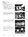
1.
Remove carburetor mount adaptors, reed cages,
stuffers, and oil pump. Note position of stator wire guide.
Measure air gap between fiber reed and reed block
as shown. The air gap should not exceed .015" (.4
mm). If clearance is excessive DO NOT attempt to
reverse the reeds to reduce the air gap. Always
replace them if damaged. Check each fiber reed for
white stress marks or missing material. Replace if
necessary.
Reed Pedal
Clearance .015"
(.38 mm) max.
Exaggerated
for illustration
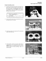
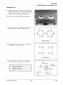
V.E.S. Removal - 440
2.
Pull back cover retainer clip while holding the
cover in place.
3.
Remove cover and return spring.
4.
If the spring stays in the cover, hold the cover
with spring facing toward you. Rotate spring in
a counterclockwise direction while pulling
outward on the spring. Do not distort the spring
upon removal.
1. Hold Cover
2. Slide Clip
Down
Cover
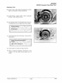
CAUTION: Do not attempt to remove the plastic
valve piston at this time. The bellows must first be
removed from the piston or damage may occur to
the bellows or piston.
5.
Remove two (5mm) hex screws from valve
housing.
6.
Note location of "TOP" marks on housing and
exhaust valve. Lift entire valve assembly from
cylinder along with gasket.
Rotate to
remove~
fromcover
~~
Align TOP marks
j§)
10/98
>...,
Retainer C~ ~
3.38
~
\UP
Housing Bolts: Appl
Loctite ™ 242(blue)
Torque: 108 in. lbs.
(1.24 kg-m)
Polaris Industries Inc.
ENGINES
440/500 Domestic Case Reed Twin
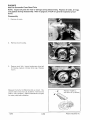
Disassembly, Cleaning, Inspection- VES- 440 XCR
1. Carefully remove the fastener strap in the area
shown. Use care to avoid cutting the bellows.
2. Fold back upper edge of bellows to expose lower edge of piston.
Lower Clamp
3. Hold exhaust valve securely and remove piston
by turning the 1Omm hex counterclockwise.
/
Housing
4. Slide exhaust valve out of housing.
5. Remove 0-ring from exhaust valve shaft.
~
Gasket
6. Compress lower spring clamp and remove bellows and clamp.
0-ring
·~·
·~·
10mm
Hex
\.,
~/)C?
7. Clean 0-ring and bellows in warm water and
mild detergent. Inspect bellows for holes, distortion or damage. Replace if necessary. Inspect 0-ring for damage.
~
~Hold exhaust valve
then remove pisto
8. Clean all other parts with solvent. Be sure all
parts are thoroughly clean.
9. Inspect the actuator port in cylinder and valve
housing. Be sure it is clear and not obstructed
by debris or carbon.
1 O.Carbon deposits can be removed from valve
with a Scotch Brite'" pad or similar soft abrasive brush.
11. Lubricate exhaust valve with Polaris Premium
Gold 2-cycle engine lubricant. Install valve in
cylinder and move it through the entire travel
range to check for free movement without binding. If the valve sticks anywhere in the travel
range, check the valve and valve bore in the cylinder for carbon deposits and clean if necessary.
Polaris Industries Inc.
3.39
10/98
ENGINES
440/500 Domestic Case Reed Twin
V.E.S. Assembly - 440 XCR
1. Install lower clamp over small end of bellows.
2. Assemble dry. Install bellows on housing. Be
sure bellows is completely seated in groove,
and install clamp.
3. Place a new o-ring and gasket on exhaust
valve.
Align TOP marks
4. Insert exhaust valve in housing with TOP marks
aligned. Both the valve housing and valve are
marked with "TOP".
;:§}
5. Apply Loctite"' 242 to threads of exhaust valve
and install the piston. Hold exhaust valve and
torque piston to 25 in. lbs. (.28 kg-m).
6. Install valve assembly in cylinder with TOP
marks on valve and housing facing up. Apply
Loctite 242 (blue) to housing bolt threads. Install
and torque bolts to 1 08 in. lbs. (1.24. kg-m).
$1 \UP
Housing Bolts: Appl
Loctite"' 242(blue)
Torque: 108 in. lbs.
(1.24 kg-m)
7. Fit upper sealing edge of bellows into groove on
piston.
1. Compress
and Hold
Cover
8. Secure the bellows by installing the fastener
strap. NOTE: Move the valve up and down in
the full travel range and check for smooth operation. If the valve binds in any spot, check the
bellows to be sure it is not twisted on the piston.
2. Slide Clip
Up
9. Install spring and cover. Be sure spring is properly positioned on the piston and in the cover.
10/98
3.40
Polaris Industries Inc.
ENGINES
440/500 Domestic Case Reed Twin
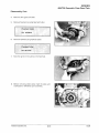
Disassembly, Cont.
7.
Remove cylinder head cover and inspect 0-rings
and sealing surfaces for damage or debris. Use
new 0-rings upon assembly.
8.
Remove cylinder base nuts. Note location of acorn
nuts on exhaust side (where applicable).
9.
Carefully remove cylinders while supporting pistons
and connecting rods to prevent piston damage.
Refer to General Inspection Procedures in this
chapter.
10. Remove outer piston pin C-clips using a scribe
through access slot in piston.
11. Place support block under piston and remove piston
pins using pin puller.
Piston Pin Puller
PN 2870386
Support Block
PN 2870390
12. Remove water pump cover from front of engine.
Polaris Industries Inc.
3.41
10/98
ENGINES
440/500 Domestic Case Reed Twin
Disassembly, Cont.
13. Remove recoil housing and drive hub.
14. Remove flywheel using heavy-duty flywheel puller.
Use drive clutch puller T-handle or a wrench to hold
puller.
Flywheel Puller
PN 2871043
T-Handle
PN 5020326
15. Before removing stator plate, note where ignition
timing marks are located, or scribe additional marks
for reference upon reassembly.
16. Mark or note location of engine mount straps and
remove.
10/98
3.42
Polaris Industries Inc.
ENGINES
440/500 Domestic Case Reed Twin
Disassembly, Cont.
17. Remove bolts and separate case halves.
bolts in order for assembly.
Keep
18. To prevent damage to snap-ring grooves, lift
crankshaft straight upward and out of lower case.
19. If pump shaft removal is necessary, remove
retaining pin from crankcase using a diagonal cutter
or similar tool.
20. Using a soft faced hammer, tap pump shaft out of
lower case half from front (water pump side) to rear
(oil pump side). Note location washers on the shaft.
Polaris Industries Inc.
3.43
10/98
ENGINES
440/500 Domestic Case Reed Twin
Disassembly, Cont.
21. Press front bushing, oil seal and mechanical seal
out of lower crankcase using a suitable (soft) drift
from the oil pump (rear) side. Be careful not to
damage bushing.
Remove bushings, seals
~
Assembly
Insert bushing into case on water pump side
using weep hole to align hole for retaining pin.
Press in until firmly seated in case. Install
retaining pin. Tap in until seated in bushing
1.
NOTE: If front bushing is replaced it may be necessary
to drill a retaining pin hole in the new bushing. If there
is no hole in the bushing:
•
Install bushing in crankcase as described above.
Remove the retaining pin from lower crankcase.
Using the retaining pin hole as a guide, carefully
drill a hole in the new bushing to the same depth
and diameter as the hole in the old bushing. Be
careful not to enlarge the retaining pin hole.
Install new retaining pin.
2.
Install oil seal with spring facing outside of
crankcase (toward you) until seated against
bushing.
3.
Lubricate and install washer on pump shaft
(water pump end). Install shaft with washer
through bushing and oil seal from the oil pump
side of case. Be sure spring stays in position on
seal lip.
4.
Install remaining washer on shaft.
5.
Lubricate and install rear bushing with new
0-ring until seated against shaft.
6.
Install oil pump, being careful to engage pump
shaft in drive shaft.
Oil Pump Mounting Screw Torque:
60 in. lbs. (.70 kg-m)
10/98
3.44
Polaris Industries Inc.
ENGINES
440/500 Domestic Case Reed Twin
Assembly, Cont.
7.
Install mechanical seal guide (special tool) on
end of pump shaft.
Washer
10.3x14x1 mm
I
@-iltbB
Mechanical Seal Guide
Tool1999 440/500
domestic engines
8.4mm: PN 2872010
8.
Lubricate seal guide and drive or press a new
mechanical seal into case until fully seated using
the seal press tool.
9.
Lubricate all crankshaft bearings with Premium
2-Cycle or Premium Gold Engine Lubricant.
Mechanical
Seal
10 ft.lbs.
kg-m)
Washer
.325x.75x.063"
10. Lightly grease pump shaft drive gear and sealing lip
of crankshaft seals.
11. Install seals on crankshaft with spring facing inward
(toward crankshaft).
12. Clean and de-grease lower crankcase and install
crankshaft assembly, aligning seals and snap ring
with grooves in case.
13. Apply a thin coating of 3-Bond 1215 sealant to lower
crankcase mating surface.
14. Install upper crankcase on lower crankcase.
15. Apply Loctite 242 to threads of bolts and install.
Torque bolts in three steps to specification outlined
in beginning of this chapter following the sequence
shown at right
MAG End
®
@
@
Polaris Industries Inc.
3.45
PTO End
®
G) G)
@
GJ
®
®
@
@®
@@
10/98
ENGINES
440/500 Domestic Case Reed Twin
Assembly, Cont.
16. Assemble engine mount straps to crankcase.
Engine Mount Strap Torque:
44-48 ft. lbs. (6.0-6.6 kg-m)
17. Lubricate main bearing oil holes with Polaris
Premium 2 Cycle or Premium Gold engine oil and
rotate crankshaft to distribute oil evenly.
18. Install a new C-clip in both pistons (inside) with gap
facing down. Be sure clip is fully seated in groove.
19. Lubricate and install new connecting rod small end
bearing in rod.
20. Install piston with arrow facing exhaust (ring
locating pins should be facing intake). Warming the
piston may help to ease installation of pin.
21. Install remaining C-clip with gap down. Be sure both
clips are fully seated on the groove.
22. Install new base gasket. Be sure gasket surface is
clean and free of nicks, burrs, or scratches.
23. Lubricate and install piston rings on piston with mark
on end of ring facing upward.
24. Place piston support under skirt and lubricate
pistons and cylinders thoroughly.
25. Align ring end gaps with locating pins and compress
rings. Install cylinder carefully with a gentle front to
rear rocking motion. Install cylinder base nuts
loosely. Do not tighten them at this time. Repeat
Steps 22-25 for other cylinder.
Straight Edge
ez:--4'
Piston Ring Cutaway
Keystone Piston Ring
Do not twist or force cylinder during installation.
26. Install new cylinder head 0-rings and install cylinder
head. Make sure 0-rings are properly seated in
grooves. Apply a light film of grease to hold 0-rings
in place if necessary.
10/98
3.46
Polaris Industries Inc.
ENGINES
440/500 Domestic Case Reed Twin
Assembly, Cont.
27. Install new cylinder head cover 0-rings and install
Make sure 0-rings are
cylinder head cover.
properly seated in grooves. Apply a light film of
grease to hold 0-rings in place if necessary.
28. Loctite 242 to threads of head bolts and install.
29. Torque head bolts to specification outlined in
beginning of this chapter in proper sequence.
00
G®
(00
@
00 0 ®
@
Cylinder Head
30. Torque cylinder base nuts outlined in beginning of
this chapter in proper sequence.
Cylinder Base
31. Install washers and water pump impeller as
shown and torque nut to 10ft. lbs. (1.38 kg-m).
Washer
10.3x14x1mm
I
1o ft.lbs.
@-,,_~Bkgm)
Impeller Nut Torque:
10Ft lbs (1.38 kgm)
Mechanical
Seal
Polaris Industries Inc.
3.47
Washer
.325x.75x.063"
10/98
ENGINES
440/500 Domestic Case Reed Twin
Assembly, Cont.
32. Install water pump cover with new gasket.
Water Pump Cover Bolt Torque:
9 Ft lbs (1.25 kgm)
33. Install new exhaust manifold gaskets and
manifold.
Exhaust Manifold Bolt Torque:
16Ft lbs (2.21 kgm)
34. Assemble V.E.S. valve.
Refer to
procedures in beginning of this section.
V.E.S.
35. Install reed valves, stutters, and carburetor
adaptors. Place stator wire guide on Mag side
carburetor adaptor bolt.
36. Install stator assembly, aligning timing marks or
marks made upon disassembly. Seal stator wires
with high temperature silicone sealant. Install and
tighten stator screws to specification.
37. Measure trigger (pulse) coil gap and compare to
specification.
Stator Screw Torque
60 in. lbs. (.69 kg-m)
Trigger (Pulse) Coil Gap
Minimum:
Maximum:
10/98
.020" (.5mm )
.040" (1.0mm )
3.48
Polaris Industries Inc.
ENGINES
440/500 Domestic Case Reed Twin
Assembly, Cont.
38. Apply Loctite"' 262 evenly to the flywheel mounting
taper on crankshaft. Install woodruff key.
39. Install flywheel. Apply Loctite '" 242 to crankshaft
threads. Install washer and nut.
40. Use flywheel holder to hold flywheel and torque nut
to specification found in beginning of this chapter.
Flywheel Holder:
PN 8700229
41. Install recoil hub and recoil housing. Torque bolts to
specification.
Recoil Hub and Housing Bolt
Torque:
108 in. lbs. (1.25 kg-m)
42. Install engine in chassis and align clutches.
43. Refer to General Inspection Procedures in this
chapter to fill and bleed cooling system and oil
pump.
Polaris Industries Inc.
3.49
10/98
ENGINES
600noo
Domestic Case Reed Twin
NOTE: Inspect all parts for wear or damage during disassembly. Replace all seals, 0-rings,
and gaskets during disassembly. Refer to pages 3.73-3.84 for general inspection procedures.
Disassembly
1.
Remove oil pump.
2.
Remove recoil housing.
3.
Remove recoil hub. Inspect waterpump drive belt
for missing, cracked, or broken drive cogs. Replace
if worn.
Measure the belt at 4 different points as shown. Replace if width is less than .25, (6.35mm). Nominal new
width is .345, (8.75mm). Refer to Maintenance chapter
for water pump belt installation.
10/98
3.50
Replace if width is
less than .25" (6.35mm)
Polaris Industries Inc.
ENGINES
600/700 Domestic Case Reed Twin
Disassembly, Cont.
4.
Remove drive gears and belt.
5.
Remove flywheel nut using flywheel holder.
Flywheel Holder
PN 8700229
6.
Remove flywheel using flywheel puller.
Flywheel Puller
PN 2871043
7.
Note the ignition timing strip on the flywheel.
8.
Before removing stator plate, mark the plate and
crankcase for reference upon assembly.
Polaris Industries Inc.
3.51
10/98
ENGINES
600nOO Domestic Case Reed Twin
Disassembly, Cont.
9.
Remove bolts holding water pump housing to
crankcase.
Loosen hose clamp and remove
housing.
10. Inspect water pump weep hole for signs of leakage
or blockage.
11. Remove crankshaft seal from housing by driving
seal to inside of housing. Replace seal if removed.
12. Remove water pump cover bolts.
10/98
3.52
Polaris Industries Inc.
60onoo
ENGINES
Domestic Case Reed Twin
Disassembly, Cont.
13. Remove impeller nut.
14. Slide shaft out back side.
15. Inspect bearings. Replace if necessary. Replace
mechanical seal using the special tools listed below.
Use the seal press to install a new mechanical seal
in cover with spring sleeve toward impeller housing.
Install seal guide over end of shaft and apply a light
film of grease to seal guide. Carefully install shaft
and bearings in cover.
Assemble 1Ox14mm
washer, impeller, washer, and nut. Torque impeller
nut to specification.
Water Pump Mechanical Seal
Installation Tool 1999 soonoo domestic engines:
8.9mm. PN 2872389
Impeller Nut Torque
10ft. lbs. (1.38 kg-m)
Polaris Industries Inc.
3.53
10/98
ENGINES
60onoo Domestic Case Reed Twin
Disassembly, Cont.
16. Remove reed cover, reed stutters, and reeds.
Reed Valve Inspection
17. Measure air gap between fiber reed and reed
block as shown. The air gap should not exceed
.015" (.4 mm). If clearance is excessive DO NOT
attempt to reverse the reeds to reduce the air
gap. Always replace them if damaged. Check
each fiber reed for white stress marks or missing
material. Replace if necessary.
Reed Pedal
Clearance .015"
(.38 mm) max.
Exaggerated
for illustration
18. Remove cylinder head.
Note condition and
placement of both cylinder head 0-rings.
19. Loosen cylinder base nuts and remove cylinders.
10/98
3.54
Polaris Industries Inc.
6oonoo
ENGINES
Domestic Case Reed Twin
Disassembly, Cont.
20. Carefully remove C-clip holding piston pin in place.
21. Remove piston pin using piston pin puller and
adaptor.
Piston Pin Puller PN 2870386
Adaptor PN 5130971
22. Remove water manifold by removing both retainer
brackets.
23. Remove bottom crankcase bolts and separate
crankcase halves.
Polaris Industries Inc.
3.55
10/98
ENGINES
600/700 Domestic Case Reed Twin
Disassembly, Cont.
24. Remove snap rings and crankshaft seals.
25. Clean thoroughly to remove all grease, oil, dirt, and
old sealant.
10/98
3.56
Polaris Industries Inc.
ENGINES
60onoo Domestic Case Reed Twin
Assembly
1.
Clean all parts
compressed air.
with
solvent
and
dry
with
2.
Apply 3-Bond™ 1215 sealant to upper crankcase
half.
NOTE: Use only 3-Bond™ 1215 sealant. Curing time
and film thickness are critical for proper bearing clearance.
3-Bond
TM
1215
PN 2871557
3.
120 Gram Tube
Set crankshaft in lower crankcase. Lubricate seal
lips with Premium All Season Grease. Make sure
seals are positioned properly with lip and spring
facing inward toward crankshaft. Install snap rings
with gap facing upward toward upper case half.
Polaris Industries Inc.
3.57
10/98
ENGINES
600/700 Domestic Case Reed Twin
Assembly, Cont.
4.
If studs were removed or new crankcase installed,
apply Loctite™ 242 to threads of studs and screw in
until bottomed. Tighten securely.
5.
Measure installed length of stud bolt. This is the
length necessary to allow cylinder installation.
Lower Crankcase Stud Height
121-124 mm (4.76-4.88") from crankshaft
parting line.
6.
Install crankcase halves together. Torque bottom
crankcase bolt to specification in the proper
sequence found in the beginning of this chapter.
7.
Install new 0-rings on water manifold.
0-rings and install manifold.
8.
Install pistons and rings. Make sure C-clips are
firmly seated in grooves. NOTE: Keystone ring
bevel must be up. Marking near ring end gap faces
upward.
Grease
Straight Edge
ez_..~
j
~
Piston Ring Cutaway
Keystone Piston Ring
10/98
3.58
Polaris Industries Inc.
ENGINES
600nOO Domestic Case Reed Twin
Assembly, Cont.
9.
Lubricate pistons, rings, upper rod bearing, and
cylinders with two stroke oil and install cylinders.
Align ring end gaps with locating pins and compress
rings. Install cylinder carefully with a gentle front to
rear rocking motion. Loosely install cylinder nuts.
1 0. Install new cylinder head 0-ring and install cylinder
head. Make sure 0-ring is properly seated in
groove.
11. Torque cylinder base bolts in proper sequence.
Refer to specifications in the beginning of this
chapter.
700 Cylinder Base
12. Torque head bolts in proper sequence. Refer to
specifications in the beginning of this chapter.
700 Cylinder Head
Polaris Industries Inc.
3.59
10/98
ENGINES
600/700 Domestic Case Reed Twin
Assembly, Cont.
13. Reassemble water pump carefully installing seal.
14. Install crankcase seal to ignition/water pump
housing from inside toward outside until bottomed
on housing. Spring and seal lip must face inward
toward crankshaft.
15. Apply 3 Bond™ sealant to pump housing crankcase
mating surface and carefully install onto crankcase.
Tighten water pump to engine hose clamp and
torque bolts to specification.
Ignition/Water Pump Housing Torque
22 Ft. lbs (3.04kgm)
16. Align timing marks and install stator.
10/98
3.60
Polaris Industries Inc.
60onoo
ENGINES
Domestic Case Reed Twin
Assembly, Cont.
17. Install flywheel and torque flywheel nut to
specification found in the beginning of this chapter.
Flywheel Holder
PN 8700229
18. Install water pump belt and recoil hub.
NOTE: See 600/700 domestic twin water pump belt
installation in chapter 2, Maintenance, for correct belt
installation
Recoil Hub Bolt Torque 96-108 in. lbs. (1.11 -1.25 kg-m)
19. Install recoil cover and oil pump. Make sure oil
pump drive slot mates properly with water pump
shaft.
20. Install reed valve, reed stuffer, and reed cover.
Polaris Industries Inc.
3.61
10/98
ENGINES
700/800 Case Reed - Fuji
NOTE: Inspect all parts for wear or damage during disassembly. Replace all seals, 0-rings,
and gaskets during disassembly. Refer to pages 3.73-3.84 for general inspection procedures.
Disassembly
1.
Remove carburetors, water outlet manifold,
secondary coils, oil pump and reed valve cage
assemblies. NOTE: Mark each components mag,
center, and PTO so they will be in the correct
location when reassembling.
2.
Remove exhaust valve assembly from
cylinder.
3.
Remove recoil housing, water pump belt guard,
water pump and flywheel nut.
each
Flywheel Holder PN 8700229
4.
Install flywheel puller and remove flywheel.
Flywheel Puller
PN 2871043
.·.CAUTION:'
Do not thread puller bolts more than 3/8" (0.5 mm) into
flywheel or stator coil damage may occur.
10/98
3.62
Polaris Industries Inc.
ENGINES
700/800 Case Reed - Fuji
Disassembly, Cont.
5.
Mark stator plate at case parting line and remove
plate.
6.
Remove head covers, heads and cylinder base
nuts.
7.
Carefully remove cylinders.
8.
Remove C-clip retainers.
9.
Use piston pin puller to remove piston pins.
Piston Pin Puller
PN 2870386
Polaris Industries Inc.
3.63
10/98
ENGINES
700/800 Case Reed - Fuji
Disassembly, Cont.
10. Remove crankcase bolts and separate crankcase
halves.
11. Inspect crankcase and crankshaft as outlined in
general inspection procedures.
12. Clea11 crankcase thoroughly to remove all grease,
oil, dirt, and old sealant.
10/98
3.64
Polaris Industries Inc.
ENGINES
700/800 Case Reed- Fuji
Assembly
1.
Grease oil pump drive gear and end seals.
2.
Position anti-rotation pins with relief in case.
3.
Apply a light film of 3 Bond™ 1215 to crankcase and
reassemble halves.
3-Bond ™ 1215
PN 2871557
Polaris Industries Inc.
120 Gram Tube
3.65
10/98
ENGINES
700/800 Case Reed- Fuji
Assembly, Cont.
4.
Install bolts and torque to specifications and pattern
found in beginning of this chapter.
5.
Install piston pin bearings.
6.
Install piston with
7.
Install C-clip retainers using tool. NOTE: The C-clip
opening should be in the up or down position. Be
sure C-clips are properly seated in groove.
arrow(~)
toward flywheel.
C-Ciip Retainer Installation Tool
PN 2870773
8.
Lightly oil rings and cylinder. NOTE: Keystone ring
bevel must be up. Marking near ring end gap faces
upward.
Straight Edge
ez_.
9.
Install new base gaskets with sealant facing (where
applicable.
Piston Ring Cutaway
Keystone Piston Ring
10. Carefully compress rings and install cylinder over
piston. Torque cylinder base nuts to specification
found in the beginning of this chapter.
10/98
3.66
Polaris Industries Inc.
ENGINES
700/800 Case Reed- Fuji
Assembly, Cont.
11. Install new head and head cover 0-rings.
0-rings
12. Install heads and torque to specification found in
beginning of this chapter.
Reed Valve Inspection
13. Measure air gap between fiber reed and reed
block as shown. The air gap should not exceed
.015" (.4 mm). If clearance is excessive DO NOT
attempt to reverse the reeds to reduce the air
gap. Always replace them if damaged. Check
each fiber reed for white stress marks or missing
material. Replace if necessary.
Reed Pedal
Clearance .015"
(.38 mm) max.
Reed Air Gap - Maximum
.015" (.4 mm)
14. Install reed cages and carburetor mounting flanges.
Polaris Industries Inc.
3.67
10/98
ENGINES
700/800 Case Reed - Fuji
Assembly, Cont.
15. Install oil pump drive gear in correct sequence.
16. Check oil pump drive gear end play.
See
adjustment in General Inspection Procedures.
17. Install oil pump.
18. Position stator plate at previously marked position
and secure in place.
19. Torque flywheel nut to specification found in
beginning of this chapter. Install new 0-ring on
water pump and grease lightly. Install pump, recoil
cup, and belt.
Flywheel Holder:
PN 8700229
20. Adjust tension on water pump belt by loosening
mounting bolts, applying tension, and re-tightening
bolts. Install recoil housing and belt guard.
Water Pump Belt Deflection -
1/8- 3/16"(.3- .4 em)
10/98
3.68
Polaris Industries Inc.
ENGINES
700/800 Case Reed - Fuji
V.E.S. Adjustment- 700/800 XCR
The RPM at which the exhaust valves open and
close can be tuned by turning the spring adjuster in
or out for the desired valve characteristics.
1.
Turning spring adjuster in:
• Creates more spring pressure
• Allows exhaust valve to open at slower rate
• For applications such as drag racing
2.
Turning spring adjuster out:
• Creates less spring pressure
• Allows exhaust valve to open at faster rate
• For applications such as trail riding
Riders can fine tune the VES to suit their riding conditions and power delivery characteristics. Base
setting is with adjuster screw flush with housing.
CAUTION: Do not turn spring adjuster too far. The
spring adjuster is turned out to its maximum when
the adjuster is flush with top of housing.
Polaris Industries Inc.
3.69
10/98
ENGINES
700/800 Case Reed - Fuji
V.E.S. Removal - 700/800 XCR
1.
Remove two mounting bolts. Remove exhaust
valve assembly from cylinder.
2.
Remove four cover bolts, cover, and return
spring.
CAUTION: Valve is spring loaded. Hold cover in
position until all bolts are removed.
3.
If the spring stays in the cover, hold the cover
with spring facing toward you. Rotate spring in
a counterclockwise direction while pulling
outward on the spring. Do not distort the spring
upon removal.
4.
With a 10 mm wrench, loosen exhaust valve
cap and remove.
NOTE: Top nut is secured to valve with adhesive.
Removing top nut may damage threads on valve.
5.
Remove
exhaust
valve
remaining
components. NOTE: 700 XCR valves are
marked "70 UP" and 800 XCR valves are
marked "79 UP". Upon installation be sure this
marking faces upward.
10/98
3.70
Polaris Industries Inc.
ENGINES
700/800 Case Reed - Fuji
Disassembly, Cleaning, Inspection - VES - 700/800 XCR
1. Clean 0-ring and bellows in warm water and
mild detergent. Inspect bellows for holes, distortion or damage. Replace if necessary. Inspect 0-ring for damage.
0-ring~·
~?
Bellow~.t;t
2. Clean all other parts with solvent. Be sure all
parts are thoroughly clean.
~·.j'
ll!J~
3. Inspect the actuator port in cylinder and valve
housing. Be sure it is clear and not obstructed
by debris or carbon.
4. Carbon deposits can be removed from valve
with a Scotch Brite"' pad or similar soft abrasive brush.
5. Lubricate exhaust valve with Polaris Premium
Gold 2-cycle engine lubricant. Install valve in
cylinder and move it through the entire travel
range to check for free movement without binding. If the valve sticks anywhere in the travel
range, check the valve and valve bore in the cylinder for carbon deposits and clean if necessary.
Polaris Industries Inc.
·./
~
3.71
10/98
ENGINES
700/800 Case Reed - Fuji
V.E.S. Assembly - 700/800 XCR
1. Replace gasket and insert exhaust valve into
valve housing.
Bevel side out
2. Install washer, beveled side out.
3. Install bellows and valve cap.
4. Install spring, valve cover, and adjuster nut.
5. Set adjuster nut according to rider preference.
Refer to page 3.69.
10/98
3.72
Polaris Industries Inc.
ENGINES
General Inspection Procedures
Cylinder Honing
The cylinder bore must be de-glazed whenever new piston rings are installed. A light honing with fine stones
removes only a very small amount of material. A proper crosshatch pattern is important to provide a surface that
will hold oil, and allow rings to seat properly. If the crosshatch is too steep, oil retention will be reduced. A crosshatch angle which is too shallow will cause ring vibration, poor sealing, and overheating of the rings due to blow-by
and reduced contact with the cylinder wall. Service life of the pistons and rings will be greatly reduced.
Cylinder Hone Selection
Selecting a hone which will straighten as well as remove material from the cylinder is very important.
Honing a cylinder with a spring loaded glaze breaker
is never advised. Polaris recommends using a rigid
type hone which also has the capability of oversizing.
These hones are manufactured by such companies as
Sunnen Products Company of St. Louis, Missouri; and
Ammco Tools, Inc., of North Chicago, Illinois.
Shown at right is the Ammco No. 3950 hone. This
hone has roughing and finishing stone sets available
to service engines with cylinder bores up to 75mm in
diameter.
De-glazing
If cylinder wear or damage is minimal, hone the cylinder lightly with finish stones following the procedure
outlined on page 3.74
Honing To Oversize
If cylinder wear or damage is excessive, it will be necessary to oversize the cylinder using a new oversize
piston and rings. This may be accomplished by either
boring the cylinder and then finish honing to the final
bore size, or by rough honing followed by finish honing.
NOTE: Portable rigid hones are not recommended for
oversizing cylinders, cylinder boring, and finish honing. The use of an arbor type honing machine is recommended.
For oversize honing always wet hone using honing oil
and a coarse roughing stone. Measure the new piston
at room temperature (see piston measurement) and
rough hone to the size of the piston or slightly larger.
Always leave .002 - .003'' (.05 - .07 mm) for finish honing. Complete the sizing with fine grit stones to provide
the proper cross-hatch finish and required piston
clearance.
EXAMPLE OF CROSS HATCH PATTERN
Inspect cylinder for taper and out-of-round. Taper or
out-of-round on the finished bore should not exceed
.0004" (.002mm).
NOTE: Always check piston to cylinder clearance and piston ring installed gap after boring/honing is complete!
Polaris Industries Inc.
3.73
10/98
ENGINES
General Inspection Procedures
Honing Procedure
1.
Wash cylinder with solvent. Clamp cylinder in a soft
jawed vise by the exhaust port studs.
2.
Place hone in cylinder and tighten stone adjusting
knob until stone contacts the cylinder walls (DO
NOT OVERTIGHTEN). Cylinders may be wet or
dry honed depending on the hone manufacturer's
recommendations. Wet honing removes more
material faster and leaves a more distinct pattern in
the bore. Using a 1/2" (13 mm) drill motor rotating
at a speed of 300-500 RPM, run the hone in and out
of the cylinder rapidly until cutting tension
decreases. Remember to keep the hone drive
shaft centered to prevent edge loading and always
bring the stone approximately 1/2" (1.3 em)
beyond the bore at the end of each stroke. Release
the hone at regular intervals to inspect bore size
and finish.
Ni-Ca-Sil Honing
Ni-Ca-Sil cylinders can be lightly honed
if the proper stone is used. Ammco
#3955 honing stones (for use with the
Ammco 3950 cylinder hone) are suitable and can be ordered through most
automotive supply stores or VST. See
General Information chapter for tool
ordering information.
Port Chamfering
Remove the sharp edges at the bottom and top of each
port whenever boring or honing is performed. Make
sure there are no sharp edges.
IMPORTANT:
Cleaning the Cylinder After Honing
It is very important that the cylinder be thoroughly
cleaned after honing to remove all grit material. Wash
the cylinder in a solvent, then in hot soapy water. Pay
close attention to areas where the cylinder sleeve
meets the aluminum casting (transfer port area). Use
electrical contact cleaner if necessary to clean these
areas. Rinse thoroughly, dry with compressed air, and
oil the bore immediately with Polaris Premium 2 Cycle
Lubricant.
NOTE: Always check piston to cylinder clearance and piston ring installed gap after boring/honing is complete!
10/98
3.74
Polaris Industries Inc.
ENGINES
General Inspection Procedures
Crankcase Inspection I Bearing Fit
Any time crankshaft bearing failure occurs and the case
is to be reused, Polaris recommends checking the bearing fit into the case halves using the following procedure.
1.
With case halves cleaned, press a replacement
bearing into each of the main bearing journals to
determine a basic amount of press fit. NOTE: Do a
comparison check of all journals by manually
forcing the bearing into the bearing seats noting if
any are noticeably loose or tight. Normal hand
installation will be an indication of the
recommended interference fit. If the bearing falls
out of the case when the case is inverted, or if the
crankcase bearing surface is severly galled or
damaged, the case should be replaced.
Crankcase Bearing Interference Fit:
C-3- .0006" (.015mm)
C-4- .001" (.025mm)
Crankshaft Main Bearing Inspection
1.
Clean crankshaft thoroughly and oil main and
connecting rod bearings with Polaris Premium 2
engine oil. Carefully check each main bearing on
the shaft.
NOTE: Due to extremely close tolerances, the bearings
must be inspected visually, and by feel. Look for signs
of discoloration, scoring or galling. Turn the outer race
of each bearing. The bearings should turn smoothly and
quietly. The inner race of each bearing should fit tightly
on the crankshaft. The outer race should be firm with
minimal side to side movement and no detectable up
and down movement. Replace any loose or rough bearings.
Polaris Industries Inc.
3.75
10/98
ENGINES
General Inspection Procedures
Connecting Rod (Big End) Bearing Inspection
1.
Measure connecting rod big end side clearance with
a feeler gauge. Clearance should be equal on all
rods (within .002"). Rotate rod on crankshaft and
check for rough spots. Check radial end play in rod
by supporting rod against one thrust washer and
alternately applying up and down pressure.
Replace bearing, pin, and thrust washers if side
clearance is excessive or if there is any up and down
movement detectable in the big end bearing.
NOTE: Specialized equipment and a sound knowledge
of crankshaft repair and straightening is required to perform crankshaft work safely and correctly. Crankshaft
repair should be performed by trained Polaris seNice
technicians in a properly equipped shop.
Piston Pin I Needle Bearing Inspection
1.
Clean needle bearing in solvent and dry with
compressed air.
2.
Inspect needle cage carefully for cracks or shiny
spots which indicate wear. Replace needle bearings
if worn or cracked, and always replace them if piston
damage has occurred.
3.
Visually inspect piston pin for damage, discoloration,
or wear. Run your fingernail along the length of the
pin and replace it if any rough spots, galling or wear is
detected.
Connecting Rod Small End Inspection
1.
Clean small end of connecting rod and inspect inner
bore with a magnifying glass. Look for any surface
irregularities including pitting, wear, or dents.
2.
Run your fingernail around the inside of the rod and
check for rough spots, galling, or wear.
3.
Oil and install needle bearing and pin in connecting
rod. Rotate pin slowly and check for rough spots or
any resistance to movement. Slide pin back and
forth through bearing while rotating and check for
rough spots.
4.
With pin and bearing centered in rod, twist ends back
and forth in all directions to check for excessive axial
play. Pull up and down evenly on both ends of pin to
check for radial play. Replace pin and bearing if there
is any resistance to rotation or excessive axial or
radial movement. If play or roughness is evident with
a new pin and bearing, replace the connecting rod.
10/98
3.76
Polaris Industries Inc.
ENGINES
General Inspection Procedures
Crankshaft Truing
Lubricate the bearings and clamp the crankshaft securely in the holding fixture. On three cylinder crankshafts,
straighten one of the ends (Magneto or PTO) and then straighten the center section. Place the center section
in the holding fixture and then straighten the remaining end. If truing the crankshaft requires striking with a hammer, always be sure to re-check previously straightened areas to verify truing. Refer to the illustrations below.
•
Crankshaft Alignment Fixture
PN 2870569
NOTE: The rod pin position in relation to the dial indicator position tells you what action is required to
straighten the shaft.
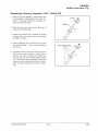
5.
To correct a situation like the one shown in the
illustration at right, strike the shaft at point A with a
brass hammer.
NOTE: The rod pin position in relation to the dial indicator position tells you what action is required to
straighten the shaft.
6.
To correct a situation like the one shown in the
illustration at right, squeeze the crankshaft at
point A. (Use tool from alignment kit).
SUPPORT CRANKSHAFT
AT THESE TWO BEARINGS
HIGH .002 (.05mm)
.HIGH .005 (.13mm)
•
7.
If the crank rod pin location is 180° from the dial
indicator (opposite that shown above), it will be
necessary to spread the crankshaft at the A
position as shown in the illustration at right. When
rebuilding and straightening a crankshaft,
straightness is of utmost importance. Runout
must be as close to zero as possible.
NOTE: Maximum allowable runout is .004" (.1 mm).
Polaris Industries Inc.
3.77
HIGH .002 (.05mm)
14-~A
• HIGH .005 (.13mm)
•
10/98
ENGINES
General Inspection Procedures
Crankshaft Indexing
Polaris crankshafts are pressed together or "indexed" so
the connecting rod journal center lines are 180° (twins) or
120° (triples) apart from each other.
It is sometimes necessary to check multi-cylinder crankshafts to verify that one cylinder has not been forced out
of position relative to the other cylinder or cylinders.
Causes for out-of-index crankshafts include but are not
not limited to:
•
Hydrolock from water or fuel;
Impact to drive clutch from foreign object or accident;
Abrupt piston or other mechanical failure;
Engine lock-up due to drive belt failure;
Following is a method of checking:
Disconnect battery ground cable and all spark plug high
tension leads; ground high tension leads to engine. Disconnect lanyard from engine stop switch before proceeding with the following steps.
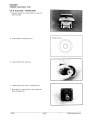
1.
Securely fasten a degree wheel on the flywheel or
PTO end of crankshaft. Use a large degree wheel for
more accuracy, and make sure it is mounted
concentrically with the crankshaft center line.
2.
Sharpen a coat hanger or section of welding rod and
anchor it to a convenient spot. Point the sharpened
end at the outer perimeter of the degree wheel.
3.
Install a dial indicator into the magneto end cylinder
spark plug hole (front) (#1 ). (The ignition timing is
referenced by the magneto end.)
4.
Rotate the engine to bring the piston to top dead
center (TDC) on the cylinder with the indicator
installed.
5.
Locate TDC as accurately as possible by finding the
center of the point where there is no piston
movement. "Zero" the dial indicator at this point.
Continue to rotate the crankshaft in the normal
direction of rotation until the dial indicator reads .1 00"
(2.54mm) after top dead center (ATDC).
Dial Indicator
.100 ATDC
Degree
Wheel
IMPORTANT: Do not allow the crankshaft to move
from this position.
10/98
3.78
Polaris Industries Inc.
ENGINES
General Inspection Procedures
Crankshaft Indexing (Continued)
6.
Bend the pointer or move the degree wheel until the
pointer aligns with the 180 or 120° mark on the
degree wheel.
7.
With the pointer aligned, make sure the degree wheel
and pointer are secured and will not move out of
position. Re-check accuracy of this location by
repeating steps 4. and 5 .. The pointer should align
with the 180 or 120° mark when the dial indicator
reads .1 00" (2.54mm) ATDC.
IMPORTANT: Do not move the degree wheel or pointer
after the initial setting on the mag end cylinder - simply
read the wheel and dial indicator.
8.
Remove the dial indicator and install in cylinder #2 or
center cylinder. Repeat steps 4. and 5. Note the
degree wheel indication when the dial indicator reads
.1 00" ATDC. It should be 180 or 120° (± 2°) from
cylinder #1. Repeat procedure on PTO cylinder (#3)
where applicable. Cylinder #3 should also be 120°(±
2°) from cylinder #1.
Symptoms of an out of index crankshaft can include:
Difficulty calibrating carburetor (repetitive plug
fouling on one cylinder with no other cause);
•
•
Unexplained piston failure on one cylinder (i.e.
severe detonation, broken ring lands, piston holing);
Excessive vibration of engine, backfiring, etc.;
•
Rough idle, poor top speed.
Polaris Industries Inc.
3.79
10/98
ENGINES
General Inspection Procedures
Cylinder Head Inspection
1.
Inspect each cylinder head for warping. Replace
cylinder head if warp exceeds service limit.
Cylinder Head Warp
Service Limit: .003" (.08mm)
Cylinder Measurement
1.
Inspect each cylinder for wear, scratches, or
damage. If no damage is evident, measure the
cylinder for taper and out of round with a
telescoping gauge or a dial bore gauge. Measure
the bore 1/2" from the top of the cylinder; in line with
the piston pin and 90° to the pin to determine if the
bore is out of round. Repeat the measurements at
the middle of the cylinder and the bottom of the
cylinder to determine taper or out of round at the
bottom. Record all measurements.
Cylinder Taper
Limit: .002 Max.
Cylinder Out of Round
Limit: .002 Max.
10/98
3.80
Polaris Industries Inc.
ENGINES
General Inspection Procedures
Piston Inspection/Measurement
1.
Check piston for scoring or cracks in piston crown or
pin area. Excessive carbon buildup below the ring
lands is an indication of piston, ring or cylinder wear.
2.
Measure piston outside diameter at a point 10 mm
(3/8") up from the bottom of the skirt at a 90° angle
to the direction of the piston pin. Record the
measurement for each piston.
NOTE: The piston must be measured at this point to
provide accurate piston-to-cylinder clearance measurement.
3.
Subtract this measurement from the minimum
cylinder measurement recorded previously.
If
clearance exceeds the service limit, the cylinder
should be re-bored and new pistons and rings
installed.
Piston Ring Installed Gap
1.
Position ring 1/2" (1.3 em) from the top of the
cylinder using the piston to push it squarely into
place. Measure installed gap with a feeler gauge at
both the top and bottom of the cylinder.
NOTE: A difference in end gap indicates cylinder taper.
The cylinder should be measured for excessive taper
and out of round. Replace rings if the installed end gap
exceeds the service limit.
NOTE: Always check piston ring installed gap after reboring a cylinder or when installing new rings. Refer to
specifications in chapter 1 for piston ring installed gap.
Straight Edge
12Z-i
Piston Ring Cutaway
Keystone Piston Ring
Polaris Industries Inc.
3.81
10/98
ENGINES
General Inspection Procedures
Oil Pump Operation and Troubleshooting
Any time the engine is disassembled or repaired, it is important that the oil supply from the pump to the engine
be checked.
NOTE: Banjo type or pressed in valves should open with 2 to 71bs. of pressure. Perform this test with 40:1 premix
in fuel tank.
With engine in chassis, oil reservoir full, and pump
bled, remove two oil feed line banjo bolts (A) from
their location on the manifold or carburetors. NOTE:
Install new sealing washers upon installation on
either side of the banjo check valve.
1.
2.
Loosely thread only the banjo bolts back into the
manifold or carburetors.
3.
Place oil feed lines with their check valves away
from the clutch area. Start the engine and let it idle
at normal idle RPM.
4.
Lift oil pump control lever up to its maximum flow
position.
5.
Drops of oil should be visible from the banjo check
valves after the engine is idled one to two minutes,
with a drop occurring approximately every few
seconds.
6.
If oil does not flow from one of the check valves,
remove oil line from check valve and again idle
engine. If oil then flows, the check valve is defective
and must be replaced.
7.
If oil does not flow with check valves removed from
their feed lines, the malfunction is one of the
following:
•
lnline filter blocked
10/98
•
Air not bled from oil pump
•
Feed lines leaking
•
Oil tank vent restricted or kinked
•
Defective pump.
3.82
Pressed
Apply Pressure Here
To Test
Banjo
Polaris Industries Inc.
ENGINES
General Inspection Procedures
Oil Pump Bleeding
The oil pump must always be bled following any service to the injector system or engine which allows the loss
of oil and subsequent entrapped air during reassembly.
1.
Fill oil reservoir with Polaris injector oil.
2.
Loosen bleed screw (A). After a short time oil should
flow from beneath the screw head to indicate the
pump is free of air.
3.
Tighten bleed bleed screw securely.
Oil Pump Adjustment- All Models
NOTE: Adjust carburetor synchronization, idle speed,
and throttle cable free play before adjusting oil pump.
1.
Stop engine.
2.
With throttle in its idle position, the pump lever index
mark (A) must align with the pump housing boss
index mark (B). On domestic 500 cc engines, align
the dot on the pump arm to the mark on pump.
3.
Loosen lock nuts on cable housing sleeve and vary
cable housing length as required until proper marks
are aligned. NOTE: Verify pump lever moves upon
initial throttle opening.
Oil Pump Bushing End Play Adjustment- Fuji
If the oil pump, crankcase, or any pump drive component
is replaced, inspect the drive gear bushing end play using the following procedure:
1.
Assemble oil pump drive gear assembly. Be sure the
bushing is fully seated in the crankcase.
2.
Measure distance from oil pump mounting surface to
bushing. Call this measurement "A".
Polaris Industries Inc.
3.83
10/98
ENGINES
General Inspection Procedures
Oil Pump Bushing End Play Adjustment- Fuji, continued
3.
Measure distance from oil pump mounting flange
surface to end of seal flange as shown. Call this
measurement "B".
4.
Subtract measurement "B" from "A" to determine
total bushing end play.
5.
Measure thickness of existing shims and subtract
from total bushing end play determined in step 3.
6.
Add or subtract shims as required to provide
specified end play.
7.
Lightly grease a new 0-ring and install it on the
pump. Install pump, engaging slot in shaft with drive
gear. Apply Loctite™ 242 to bolts and torque evenly
to 78 in. lbs. (.9 kg-m).
End Play
.008- .016" (.203- .406 mm)
Optional Shims:
PN 3083671 = .006"(.15mm)
PN 3083672 .012" (.3mm)
PN 3083673 .024" (.6mm)
=
=
Oil Pump Mounting Bolt Torque
(242 Blue)
78 in. lbs (.9 kg-m)
10/98
3.84
Polaris Industries Inc.
ENGINES
Cooling System Bleeding Procedures
A
WARNING
Never remove the pressure cap when the engine is warm or hot. If the pressure cap is to be removed, the engine
must be cool. Severe personal injury could result from steam or hot liquid.Use of a non-standard pressure cap
will not allow the recovery system to function properly. If the cap should need replacement, install the correct
Polaris cap with the same pressure rating. Refer to the appropriate parts manual.
NOTE: Always use Polaris premium antifreeze 60/40 premix. Bleed system at specified RPM or air will remain
trapped in system, which may result in overheating.
Filling and Bleeding Procedure
If the cooling system should become low in the reservoirtank and/or filler neck, the system should be bled of any
trapped air using one of the following procedures, depending on model.
Lift Lock L~leed
I
Fuji {except 700/800 XCR)
1.
2.
3.
4.
Elevate front end of machine approximately 10" (25
em).
Fill coolant reservoir to indicated maximum level line.
Remove pressure cap and slowly add coolant until
coolant level iseven with top of filler neck. Install
pressure cap and lift lever.
Install the pressure cap with the lever lock up in its
release position and run the engine at low idle RPM (600
RPM± 100) to allow all air to purge and prevent trapped
air which can lead to overheating and engine damage.
Reset idle to specs after bleeding. System is properly
bled when no air bubbles are visible in overflow line
when RPM is increased slightly. Lock pressure cap and
fill the coolant reservoir to proper level.
;, · .
~
,
r---------,
Remote Filler Neck
Bleed at 600 RPM
Caution:
Increase RPM
slowly when lever
lock is up to avoid
loss of coolant.
Remote Filler Neck Shown
Bleed Screw
700 and 800 XCR Bleeding Procedure
1.
2.
Fill cooling system. Leave pressure cap off.
With engine running at specified idle speed, loosen
bleed screw on water outlet manifold.
3.
Continue adding antifreeze mixture to reservoir bottle
until system is purged of air.
4.
Close bleed screw and tighten securely.
5.
Fill reservoir bottle until it is between the minimum and
maximum fill marks.
6.
Replace pressure cap.
7.
Start engine and check for leaks.
700/800 XCR
Bleed Screw
500/GOOnoo Domestic Twins Bleeding Procedure
1.
Fill cooling system . Leave pressure cap off.
2.
With engine running at specified idle speed, loosen
bleed screw on thermostat housing.
3.
Continue adding antifreeze mixture to reservoir until
system is purged of air.
4.
Close bleed screw and tighten securely.
5.
Fill reservoir bottle until coolant level is between the
minimum and maximum fill marks.
6.
Replace pressure cap.
7.
Start engine and test for leaks.
Polaris Industries Inc.
3.85
500/600/700 Domestic Twins
10/98
ENGINES
Cooling System -Indy 500/500 RMK, Classic, Classic Touring
Widetrak LX, XLT Classic, XLT Touring
Note: Filter is located before
the check valve. Coolant flows
from tank, through filter, then
check valve, to water pump.
RH c oler
Crossover hose
Hose, filler/RH
cooler
LH cooler
Hose, side to center cooler
Hose, center cooler to pump
ENGINE
NOTE: When leak testing cooling system, system
pressure should not exceed 2 lbs. less than cap pressure. Refer to filling and bleeding procedure on page
3.85.
LH COOLER
10/98
3.86
RH COOLER
Polaris Industries Inc.
ENGINES
Cooling System - 600 XC/SP, 700 XC/SP
Bypass Hose Not Shown
wear strip
coolers
Hose, close-off to wear strip cooler
Protective conduit
Hose, engine out to bottom close-off (center cooler)
ENGINE
BRAKE
COOLER
NOTE: When leak testing cooling system, system
pressure should not exceed 2 lbs. less than cap pressure. Refer to filling and bleeding procedure on page
3.85.
CENTER
COOLER
•
t
TUNNEL STRIP
COOLERS
Polaris Industries Inc.
3.87
10/98
ENGINES
Cooling System- 600 RMK, 700 RMK, 700 SKS
Bypass Hose Not Shown
Hose, tee to
brake cooler
Protective conduit
Hose, engine out to bottom close-off
Hose, tee to pump in
ENGINE
\
BRAKE
COOLER
NOTE: When leak testing cooling system, system
pressure should not exceed 2 lbs. less than cap pressure. Refer to filling and bleeding procedure on page
3.85.
COOLANT
BOTTLE
TUNNEL COOLERS
10/98
3.88
Polaris Industries Inc.
ENGINES
Cooling System - 440 XCR
Hose, tee to center
cooler
Hose, close-off to wear strip coolers
ENGINE
~~ COOLANT
'=:=:::::::!~CJ1t--~~ BOTTLE
NOTE: When leak testing cooling system, system
pressure should not exceed 2 lbs. less than cap pressure. Refer to filling and bleeding procedure on page
BRAKE
COOLER
3.85.
t
~
Polaris Industries Inc.
3.89
TUNNEL STRIP
COOLERS
10/98
ENGINES
Cooling System - 500 XC/SP
Hose, rear wear strip coolers
Hose, tee to bottle
Hose, engine out to brake cooler
Hose, tee
to center
cooler
Hose, close-off to wear
strip cooler
Hose, tee out
to pump in
Hose, bypass out to tee in
ENGINE
NOTE: When leak testing cooling system, system
pressure should not exceed 2 lbs. less than cap pressure. Refer to filling and bleeding procedure on page
3.85.
BRAKE
COOLER
•
10/98
3.90
TUNNEL STRIP
COOLERS
Polaris Industries Inc.
ENGINES
Cooling System - XLT Special
RH cooler
Center cooler
Hose, filler out
Hose, engine out
to filler
LH cooler
Hose, side to center
__},
ll
ENGINE i+1
II
I
NOTE: When leak testing cooling system, system
pressure should not exceed 2 lbs. less than cap pressure. Refer to filling and bleeding procedure on page
3.85.
•
/:
l((
'
.
LH COOLER
Polaris Industries Inc.
3.91
..
\\
I
..
CENTER
COOLER
FILLE R
0
~
I
'
.
RH COOLE
10/98
ENGINES
Cooling System - 700/800 XCR
Hose, pump to surge tank, lower
Ho e, tee to rear cooler
Hose, crossover, short
Crossover hose
Hose, center cooler to top surge tank fitting
BRAKE COOLER
NOTE: When leak testing cooling system, system
pressure should not exceed 2 lbs. less than cap pressure. Refer to filling and bleeding procedure on page
3.85.
SURGE
TANK
t+
LH COOLE
u
RH COOLER
TUNNEL COOLERS
10/98
3.92
Polaris Industries Inc.
ENGINES
Recoil Starter Spring Replacement
Disassembly
Wear eye protection when servicing recoil. Spring can unwind suddenly and unexpectedly if dislodged.
1.
Remove recoil handle and allow rope to retract and
spring to unwind completely.
2.
Remove retaining nut, friction plate, and ratchet pawl
from reel face.
3.
Lift reel assembly straight up, out of housing. NOTE:
If spring tension is relieved and the reel is lifted
straight out, the spring will most likely remain in the
housing; however-be sure to heed caution above.
Assembly
1.
If the spring was removed, reinstall it by spiraling
counterclockwise toward the center.
2.
Lubricate center shaft and spring with grease.
Premium All Season Grease
PN 2871423 (14 oz.)
3.
Wind rope in a counterclockwise direction around
outside of reel, as viewed from ratchet side of reel.
4.
Pass end of rope through rope guide and slide reel
down onto shaft and spring. NOTE: Make sure reel
tab engages hook on end of spring.
5.
Reinstall ratchet pawl onto reel face.
NOTE:
Ratchet spring must hold ratchet in retracted
position.
6.
Reinstall friction plate with one end of friction spring
in hole on end of ratchet pawl.
7.
Reinstall flange nut and torque to 5 ft. lbs. (.69 kg/m).
8.
Pull recoil rope to full extension and align notch on
outside edge of reel with housing rope guide hole.
9.
Using a needle nose pliers or hooked wire, pull a loop
of rope through the notch into center of housing.
10. Holding side of rope loop attached to reel, wind reel
counterclockwise until coil bind is felt. Then unwind
reel between one and two turns.
11. Pull loop to outside of housing by pulling on rope
handle.
12. Allow rope to fully retract and check for normal recoil
and ratchet operation.
Polaris Industries Inc.
3.93
10/98
ENGINES
Troubleshooting
PROBABLE CAUSE
PROBLEM
Will not start!
hard starting
-Check ignition switch for run position, moisture contamination
-Check auxiliary shut-off switch operation
-Check fuel supply
-Check wiring from engine to coil(s) or spark plug(s)
-Check spark plug(s)
-Disconnect engine connector to eliminate any shorts that might be in the system
-If starter won't work (electric models), check wires from starter solenoid and battery or check battery
and battery cables
-Open or broken reed valves
Low compression
-Crankcase plug is out
-Head gasket faulty
-Poor ring sealing, piston damage
No spark
-Spark plug fouled
-Secondary coil faulty or wires disconnected; poor ground on secondary coil mount
-Primary coil shorted or open
-Ignition switch shorted, contaminated with moisture
-Auxiliary switch shorted or contaminated with moisture
Engine idles but -Restricted fuel flow/air flow
no acceleration -Clogged main jet
-Timing
-Clutching
-Engine not running on all cylinders
Engine runs but
fails to reach
maximum RPM
-Clogged fuel filter
-Incorrect track tension
-Incorrect main jet
-Throttle slides not fully open
-Chain too tight
-Clutching
-Excessive driveline friction (Hi Fax overheating)
-Engine not running on all cylinders
Engine runs but
fails to idle
-Incorrect air mixture setting
-Throttle stop screw incorrectly adjusted
-Restricted pilot jet
-Low compression
-Tight belt
-Piston damage
-Enricher plunger not seating properly
Engine runs,
but overloads
with fuel
-Enricher plunger are not seating properly
-Fuel pump diaphragm is ruptured (caused by engine backfiring)
-Carburetor slides are not synchronized
-Main jet too large
-Needle and seat not seating properly
-Incorrect float level
-Check reed valve condition
Carburetion and -Verify all tune up adjustments: carb sync, oil pump adjustment, pilot screw setting, spark plug type
and gap, venting for carbs, proper jetting for altitude and temperature, belt tension, clutch operation. If
plug fouling
tune up items are correct, check: float level, jet needle position, jet needle wear, inlet needle and seat
wear, spark quality, etc.
Engine runs but
overheats
-Coolant level low or air in cooling system
-Incorrect main jet
-Incorrect timing
-Incorrect spark plug
-Water pump belt loose or broken
-Cooling restriction
-Inadequate snow for cooling (ice and/or marginal conditions)
Battery will not
charge (battery
equipped models only)
-Check for faulty connections
-Check alternator output
-Check diodes (rectifier)
-Sulphated battery
-Battery electrolyte overfilled or low
-Refer to alternator testing in chapter 9, electrical
10/98
3.94
Polaris Industries Inc.
ENGINES
Troubleshooting
PROBABLE CAUSE
PROBLEM
Lights don't
work
-Engine must be running
-Check wiring harness connector
-Check for burned out bulbs
-Check wiring for shorts or loose connections
-Disconnect taillight if headlight works, short is in taillight wiring or taillight
Unit fails to propel itself
-Check belt (center distance)
-Check clutch
-Check chain
-Check drive sprocket assembly
-Track frozen or stuck
Track wears un- -Check tension
-Check for proper alignment
evenly
-Check for loose, bent, or broken suspension parts
Chain case
overheating
-Check oil level
-Check chain tension
-Check track assembly
Polaris Industries Inc.
3.95
10/98