1
CHAPTER 9
ELECTRICAL
Ignition Timing Specifications . . . . . . . . . . . . . . . . . . . . . . . 9.1
Routing Diagram - Indicator Lights - 340 Touring . . . . . . . . 9.2
Multimeter Usage . . . . . . . . . . . . . . . . . . . . . . . . . . . . . . . . . . . 9.3-9.5
Typical Timing Advance Curves . . . . . . . . . . . . . . . . . . . . . . 9.6
Timing Curves. . . . . . . . . . . . . . . . . . . . . . . . . . . . . . . . . . . . . . 9.7-9.13
Conversion Chart- Degrees to Piston Position . . . . . . . . . 9.14
Timing Procedures - Exploded Views . . . . . . . . . . . . . . . . . . 9.15-9.20
Timing Procedures -All Models . . . . . . . . . . . . . . . . . . . . . . . 9.21
Operating RPM Timing Check . . . . . . . . . . . . . . . . . . . . . . . . 9.22
Battery Service . . . . . . . . . . . . . . . . . . . . . . . . . . . . . . . . . . . . . 9.23-9.24
Dynamic Testing of Electric Starter System . . . . . . . . . . . . . 9.25
Static Electric Starter System Testing . . . . . . . . . . . . . . . . . . 9.26
Electric Starter Assembly . . . . . . . . . . . . . . . . . . . . . . . . . . . . 9.27
Starter Installation . . . . . . . . . . . . . . . . . . . . . . . . . . . . . . . . . . 9.28
Lighting System Output Test . . . . . . . . . . . . . . . . . . . . . . . . . 9.29
Alternator Output Test . . . . . . . . . . . . . . . . . . . . . . . . . . . . . . . 9.29
Alternator Output- Pulse System . . . . . . . . . . . . . . . . . . . . . 9.30
Typical Exciter, Pulser or Lighting Coil Replacement . . . . 9.31
Electrical Testing . . . . . . . . . . . . . . . . . . . . . . . . . . . . . . . . . . . 9.32-9.33
Coolant High Temperature Indicator Testing . . . . . . . . . . . . 9.34
Speed Control Assurance Operation . . . . . . . . . . . . . . . . . . 9.35
Speed Control Assurance Testing . . . . . . . . . . . . . . . . . . . . . 9.36
Electric Fuel Gauge Testing . . . . . . . . . . . . . . . . . . . . . . . . . . 9.37
Handlebar Warmer Testing . . . . . . . . . . . . . . . . . . . . . . . . . . . 9.38
Ignition System Troubleshooting . . . . . . . . . . . . . . . . . . . . . . 9.39
1999 Wiring Diagrams . . . . . . . . . . . . . . . . . . . . . . . . . . . . . . . 9.40-9.49
ELECTRICAL
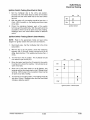
Ignition Specifications
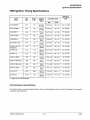
1999 Ignition Timing Specifications
Engine
Model
MM
BTDC
Inches
BTDC
Degrees
BTDC@
RPM
Acceptable Range
MM
Inches
Operating
Timing 0 8TDC
RPM
EC34-2PM051
3.67
.145
26.5±1.5
@ 3000
3.28-4.08
.129-.161
15.5° @ 7000
EC44-3PM025
3.81
.150
26±1.5
@ 3000
3.39-4.25
.133-.167
16° @ 6500
EC45PM011
4.45
.175
27±1.5
3000
3.97-4.93
.157-.195
1r @ 6500
SN44-44-98A 1
3.72
.146
25±1.5
@ 3500
3.29-4.16
.129-.163
16°@ 8250
EC50PM044
3.81
.150
26±1.5
3000
3.39-4.25
.133-.167
16° @ 6500
EC55PM011 (021)
4.45
.175
27±1.5
@3000
3.97-4.93
.157-.195
1r @ 6500
EC50PL 162{172)
(192)(202)
4.40
.173
28±1.5
@3000
3.91-4.87
.156-.191
16° @ 7500
EC58PL 160
4.40
.173
28±1.5
@3000
3.91-4.87
.156-.191
20° @ 7500
EC58PL 131
4.40
.173
28±1.5
@3000
3.91-4.87
.156-.191
20° @ 7500
SN50-44-99A2
.872
.034
12±1.5
@3000
.664-1.08
.026-.042
16° @ 8250
SN60-70-99A 1(A2)
.220
.009
6±1.5
@1750
.115-.325
.004-.013
13°@7500
S N70-70-99A 1(A2)
.220
.009
6±1.5
@1750
.115-.325
.004-.013
1r@ 7500
SN70-70-99A3
.930
.037
12±1.5
3000
.710-1.15
.033-.041
16° @ 8250
EC70PL011
2.476
.098
20±1.5
@1750
2.10-2.81
.083-.111
18°@8100
EC79PL011
4.104
.162
26±1.5
@3250
3.65-4.56
.144-.179
15°@ 8300
* Engine at room temperature
Coil Resistance Specifications
For ignition system component specifications, refer to wiring diagrams at the end of this chapter for the specific
model you are working on.
Polaris Industries Inc.
9.1
10/98
ELECTRI~AL
Routing
Diagram _ Indicator Lights
1999 340 Touring
10/98
9.2
Polaris Industries Inc.
ELECTRICAL
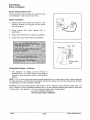
Multimeter Usage
Multimeter Usage
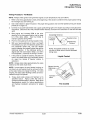
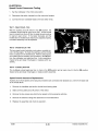
The easiest and most accurate method for testing modern
electrical components is with a digital multitester. Any good
quality multitester will work. However, due to ease of operation and durability, Polaris recommends the Fluke Model73
(PN 2870659), or Tektronix DMM155. See photo at right.
This instrument will provide a digital readout of the measured
value of the test being performed.
Listed below are the dial symbols, their meaning and what
the dial setting can be used for.
Off= Instrument Off
COMMON
(BLACK LEAD)
V- = Volts AC - measuring alternator output
Used to measure AC voltage in an electrical system. AC voltage is produced from every coil on the stator plate when a
magnet is passed by it.
Test Method
1.
Connect black lead to Com (-) meter terminal.
2.
Connect red lead to VQ (+) meter terminal.
3.
Turn selector dial to V-
4.
Connect test leads parallel with test component. The
polarity of the leads is not important.
setting.
Usage
•
Test unregulated voltage output of a stator coil
•
Test regulated voltage to the lights and handwarmers
V :-:-:-
=Volts DC - measuring battery voltage, volt drop, etc.
Used to measure DC voltage produced by a battery or rectifier.
Test Method
1.
Connect black lead to Com (-) meter terminal
2.
Connect red lead to VQ (+) meter terminal.
3.
Turn selector dial to V :-:-:- setting.
4.
Connect test leads parallel with test component.
Observe polarity.
Usage
•
Test battery voltage
•
Test DC regulator
•
Test voltage drop for bad connections
•
Test supply voltage to electric fuel gauge
•
EFI electrical testing
Polaris Industries Inc.
9.3
10/98
ELECTRICAL
Multimeter Usage
= Ohms, resistance - measuring component resistance values -testing coils, wiring, etc.
Q
Used to test resistance to the flow of electricity in a circuit or
component. A reading of OL means an open circuit or infinite
resistance. Sometimes the leads themselves will have some
resistance. Touch the leads together and subtract this resistance from the component reading to achieve the actual
reading.
Test Method
1.
Connect black lead to Com (-) meter terminal
2.
Connect red lead to VD. (+) meter terminal.
3.
Turn selector dial to Q
setting.
4.
Isolate test component from the rest of the electrical
circuit by disconnecting wires from harness.
5. Connect test leads to the circuit to be tested.
Usage
•
•
Testing coil resistance
Testing switch operation
•
Testing wire continuity
A-= Amps AC - used to test lighting coil output
Used to test the power of an alternator coil.
Test Method
1.
2.
3.
4.
5.
Connect black lead to Com (-) meter terminal
Connect red lead to 1OA (+)meter terminal.
Disconnect engine harness from system.
Connect across the specified coil wires.
Start engine and let it idle.
6.
Readings should be above 5 Amps at any RPM. NOTE:
It is not necessary to increase RPM. The reading can be
obtained at idle.
Usage
•
10/98
Testing stator coil power output.
9.4
Polaris Industries Inc.
ELECTRICAL
Multimeter Usage
A -::-:-:- = Amps DC - used to check battery charge rate, system draws, etc.
Used to check the current flow to and from the battery.
Test Method
1.
Make sure red lead is in the 1OA terminal of the meter and the black lead is in the Com (-) terminal of the meter.
2.
3.
Disconnect battery ground wire(s) from battery(-) terminal.
Connect red meter lead to battery (-) terminal.
4.
Connect black meter lead to harness ground wires and cable.
Do not operate electric starter (if equipped) or meter damage may occur.
Usage
• Testing key off current draw
• Testing key on current draw
• Testing charging system break even RPM
• Testing DC current flow (direction), is battery charging?
NOTE: When using the DC Amp settings, the red test lead must be moved to the 1OA socket on the front of the
instrument.
Polaris Industries Inc.
9.5
10/98
ELECTRICAL
Typical Timing Advance Curves
Ignition Timing
Maximum Advance
(Depending on Model)
~
w
a:
(9
w
0
w
()
z
~
Operating RPM
(Depending On
Engine) See
Data
0
<(
(9
z
~
i=
1000
2000
3000
4000
5000
6000
7000
8000
RPM
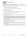
NOTE: Always verify timing of engine at room temperature only (68° F I 20° C) and at the proper RPM.
To obtain the best ignition timing accuracy and reduce the chance of error, the ignition timing specification is given
at a "flat" portion of the advance curve. This flat portion on the curve is where the ignition timing is specified.
Refer to chart on page 9.1. Ignition timing must be checked at the specified RPM, or inaccurate timing will result.
Refer to timing specifications at the beginning of this chapter.
If engine damage has occurred due to a suspected ignition related problem, verify the ignition timing is correct
at the specified operating RPM as outlined on page 9.1.
Dial Indicating The Timing Marks
Due to differences between engines, it is necessary to dial indicate the timing marks on all engines before attempting to adjust the ignition timing. To indicate the marks:
1.
Remove the mag (RH) cylinder spark plug and install the dial indicator.
2.
Rotate the crankshaft by hand while observing the dial indicator. As the piston touches the indicator plunger,
the dial will begin to rotate. Find the point where the pointer stops rotating and reverses direction. This will be
TDC (Top Dead Center).
3.
While holding the crankshaft with the piston at TDC, zero the indicator by rotating the bezel until the 0 on the
dial and the pointer align.
4.
Rotate the crankshaft opposite the direction of rotation about .250 BTDC (2 1/2 pointer revolutions).
5.
Determine the correct ignition timing position from
the ignition data charts and rotate the crankshaft in
the normal direction of rotation to that position.
(Example: If engine timing is .150 BTDC, the
crankshaft must be rotated in the normal direction
of rotation so that the dial indicator pointer does
one complete revolution and stops on 50. This
should be 1 1/2 pointer revolutions before top
center, or .150 BTDC.
6.
While holding the crankshaft at the correct timing
position, mark the flywheel (with chalk or a white
marker) directly in-line with the stationary pointer
(or line) on the fan or recoil housing through the
timing inspection window.
10/98
9.6
Polaris Industries Inc.
ELECTRICAL
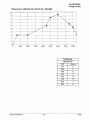
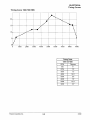
Timing Curves
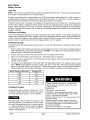
Timing Curve 1999 600 XC /600 XC SP /600 RMK
20
18
,
, ~- .
,
,, ,
16
14
12
10
8
6
,r
,,
4
2
-
.
.
...
.. .
...
.. . .... .
.
~·
...
.. 4
..
.
..
..
J.
..
.
.
..4•
'
'
'
'
'
'
,,
0
0
1000
2000
3000
4000
5000
6000
7000
8000
Timing Table
1999 600 Twin
Polaris Industries Inc.
9.7
RPM
Degrees
600
60
2000
60
4500
5000
12°
1r
6000
19°
7500
8000
13°
110
8500
60
10/98
ELECTRICAL
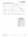
Timing Curves
Timing Curve 1999 700 XC /700 XC SP /700 SKS
20
18
~· .
.
,
,
-- .4
... ....
I
16
.. ..
,,
14
12
10
8
...
-
6
,1"
4
2
..
.. .
..
.. .. .
..
_- .
.. 4..
''
-
. .... . ""
'
'
•
,,
,,
0
0
1000
2000
3000
4000
5000
6000
7000
8000
Timing Table
1999 700 XC, XC SP, SKS
10/98
9.8
RPM
Degrees
600
60
2000
60
4500
12°
5000
17°
6000
19°
7500
16°
8000
15°
8500
11°
Polaris Industries Inc.
ELECTRICAL
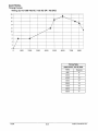
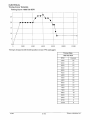
Timing Curves
Timing Curve 1999 700 RMK
....
•
•
•
20
15
10
5
0
~
•• •
•• •
...
•• •
•· ....
•
••
•
••
•
•
•• •
II
•• ••
•• •
•••.
••
''
''
•
''
'~
•
•
••
0
1000
2000
3000
4000
5000
6000
7000
8000
9000
Timing Table
1999 700 RMK
Polaris Industries Inc.
9.9
RPM
Degrees
500
60
2700
12°
3500
12°
4800
18.5°
5500
23°
8000
16°
8400
15.5°
9000
5.5°
10/98
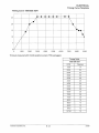
ELECTRICAL
Timing Curve Template
Timing Curve 1999 440 XCR
25
20
15
10
,
,,
5
0 '
0
'
'
'
,,
,,
,,
,,
,,
,
,,
,
,,
-. . .
,
,,
. . ._
-
~
..
..
....
••
\
'
\
'
\
\
'
'
'
_\_
'
'
4
1000
2000
3000
4000
5000
6000
7000
8000
9000
Timing Table
1999 440 XCR
10/98
9.10
RPM
Degrees
500
6
3000
25
4500
25
5500
20
7000
20
8000
16
8300
16
9000
3
Polaris Industries Inc.
ELECTRICAL
Timing Curve Template
Timing Curve 1999 500 XC I 500 XC SP
·--. -----
30
'
.'
25
'
'
•..
.. ..
'
'
'
'
20
15
·-'
10
'
'
------
.. ..
..
..
.. ..
-~
-----· -----·
'
'
'
'
'
'
5 '
'
.._
'
.
-- -~
'
'
0 '
0
1000
2000
3000
4000
5000
6000
7000
8000
9000
Timing Table
500 XC I 500 XC SP
Polaris Industries Inc.
9.11
RPM
Degrees
500
12
3900
12
4500
28
5800
28
7400
15
7900
15
8300
8.5
9000
8.5
10/98
ELECTRICAL
Timing Curve Template
Timing Curve 1999 700 XCR
•
25
20
- ---
,
,,
';'
I
~
__ .. 4
~'
·-· '•
'
'
I
4. .
'
'
'
'
I
15
'
,
'
10
'
'
I
I
I
I
5
.
• ---- --------
I
I
-- 4
,'
I
I
0
0
2000
4000
6000
8000
10000
12000
Timing is measured with throttle position sensor (TPS) unplugged.
Timing Table
1999 700 XCR
10/98
9.12
RPM
Degrees
1500
20
2000
20
2500
20
3000
20
3500
20
4000
20
4500
24
5000
26
5500
26
6000
27
6500
24
7000
24
7500
22
8000
18
8250
18
8500
12
8750
8
12750
8
Polaris Industries Inc.
ELECTRICAL
Timing Curve Template
Timing Curve 1999 800 XCR
25
,,
20
.
,,
.
·- -
, J~- -·- -4 ·-- · - - 4
-- --•-·o'
'
'
'
I
I
I
•
I
I
I
,
10
I
-
'
~
I
15
'
'
'
4~--'
--
,,
•'
'
I
I
5
I
,
I
I
I
0
0
1000
2000
3000
4000
5000
6000
7000
8000
9000
Timing is measured with throttle position sensor (TPS) unplugged.
Timing Table
1999 800 XCR
Polaris Industries Inc.
9.13
RPM
1500
2000
2500
3000
3500
4000
4500
5000
5500
6500
7000
7500
Degrees
8000
16
8250
15
8500
15
8750
12
12750
10
14
20
22
26
26
26
26
26
26
26
26
20
10/98
== s·
.....
~
Q)
DEG.
BTDC
<0
.......
~
\)
0
ill
a-
s-
g.
(/)
~
a;·
(/)
s~
~
eno. ......
1
2
3
4
5
6
7
8
9
10
11
12
13
14
15
16
17
18
19
20
21
22
23
24
25
26
27
28
29
30
31
32
33
34
35
36
37
38
39
40
EC40PL
EC44-2PM
EC44-3PM
EC45PL
EC50PL EC60PL
EC58PL EC65PL
112 MM ROD
60 MM STROKE
MM
INCHES
0.0002
0.0058
0.0232
0.0009
0.0521
0.0021
0.0926
0.0036
0.0057
0.1447
0.2083
0.0082
0.2833
0.0112
0.0146
0.3698
0.4677
0.0184
0.5770
0.0227
0.6976
0.0275
0.8294
0.0327
0.9724
0.0383
1.1265
0.0444
1.2917
0.0509
1.4678
0.0578
1.6548
0.0652
1.8526
0.0729
0.0811
2.0611
0.0898
2.2802
0.0988
2.5098
2.7497
0.1083
0.1181
3.0000
0.1284
3.2603
3.5307
0.1390
3.8110
0.1500
4.1010
0.1615
4.4007
0.1733
4.7098
0.1854
0.1980
5.0282
0.2109
5.3559
0.2241
5.6926
0.2377
6.0381
0.2517
6.3924
6.7552
0.2660
7.1263
0.2806
7.5057
0.2955
0.3108
7.8931
0.3263
8.2883
0.3422
8.6912
EC45PM
EC55PM
EC34-2PM
EC59PL
EC68PL
EC70PL
EC75PL
EC79PL
EC80PL
120 MM ROD
125 MM ROD
103 MM ROD
65MM STROKE
55.6 MM STROKE
65 MM STROKE
MM
INCHES
INCHES
MM
INCHES
MM
0.0063
0.0002
0.0062
0.0002
0.0054
0.0002
0.0252
0.0008
0.0010
0.0249
0.0010
0.0215
0.0566
0.0022
0.0019
0.0561
0.0022
0.0484
0.1006
0.0039
0.0040
0.0997
0.0860
0.0034
0.1558
0.0061
0.1343
0.0053
0.1571
0.0062
0.2261
0.0089
0.2242
0.1933
0.0076
0.0088
0.3076
0.0121
0.3050
0.0120
0.2630
0.0104
0.3981
0.0157
0.3432
0.0135
0.4016
0.0158
0.5079
0.0198
0.4341
0.0171
0.0200
0.5036
0.6265
0.0247
0.6212
0.0245
0.5355
0.0211
0.7575
0.0298
0.7510
0.0296
0.6474
0.0255
0.9006
0.8930
0.7698
0.0303
0.0355
0.0352
1.0559
0.0416
1.0470
0.0355
0.0412
0.9025
1.2232
0.0482
1.2129
0.0478
1.0456
0.0412
1.4026
0.0552
1.3908
0.0548
1.1989
0.0472
1.5804
1.3624
0.0536
1.5938
0.0627
0.0622
1.7969
0.0605
0.0707
1.7818
0.0701
1.5359
2.0117
0.0792
1.9948
0.0785
1.7195
0.0677
2.2193
0.0874
1.9130
0.0753
2.2380
0.0881
2.4759
2.1163
0.0833
0.0975
2.4552
0.0967
2.3294
0.0917
2.7252
0.1073
2.7024
0.1064
2.9857
0.1175
2.9608
0.1166
2.5521
0.1005
3.2574
0.1282
2.7843
0.1096
3.2303
0.1272
3.5401
0.1394
3.5107
0.1382
3.0260
0.1191
0.1290
0.1509
3.8019
0.1497
3.2769
3.8336
0.1393
4.1379
0.1629
4.1038
0.1616
3.5370
0.1498
4.4528
0.1753
4.4161
0.1739
3.8062
0.1608
4.0843
4.7782
0.1881
4.7389
0.1866
0.1721
5.1138
0.2013
5.0719
0.1997
4.3712
0.2149
0.2132
4.6667
0.1837
5.4595
5.4149
4.9708
0.1957
5.8152
0.2289
5.7679
0.2271
6.1807
0.2433
5.2832
0.2080
6.1306
0.2414
6.5559
0.2581
6.5028
5.6039
0.2206
0.2560
0.2336
6.9405
0.2732
6.8845
0.2710
5.9326
7.3343
7.2754
6.2693
0.2468
0.2888
0.2864
7.7372
7.6753
6.6138
0.2604
0.3046
0.3022
0.2742
8.1491
0.3208
8.0840
0.3183
6.9658
8.5015
0.3347
7.3253
0.2884
8.5696
0.3374
0.3515
7.6920
0.3028
0.3543
8.9274
8.9986
8.0659
0.3176
9:3616 ~0.3686
_Jl.4~Q__ ~.37!§
EC25PF
EC25PS
EC44PT
EC44PQ
EC44PM
Domestic 440
Domestic 500
Domestic 600
Domestic 700
136 MM ROD
120 MM ROD
128 MM ROD
68 MM STROKE
64 MM STROKE
60MM STROKE
MM
INCHES
MM
INCHES
INCHES
MM
0.0065
0.0003
0.0057
0.0002
0.0002
0.0061
0.0259
0.0010
0.0010
0.0228
0.0009
0.0244
0.0023
0.0582
0.0514
0.0022
0.0020
0.0548
0.0041
0.1035
0.0913
0.0038
0.0036
0.0974
0.1617
0.0064
0.0060
0.1426
0.0056
0.1522
0.2327
0.0092
0.0086
0.2053
0.0081
0.2190
0.0125
0.3166
0.0117
0.2793
0.0110
0.2979
0.4132
0.0163
0.0153
0.3646
0.3889
0.0144
0.5226
0.0206
0.4919
0.0194
0.4612
0.0182
0.0254
0.6448
0.0239
0.5689
0.0224
0.6068
0.7795
0.0307
0.6878
0.0289
0.0271
0.7336
0.0365
0.9268
0.8178
0.0343
0.0322
0.8723
1.0867
0.0428
0.0403
0.9588
0.0377
1.0227
1.2589
0.0496
1.1108
0.0466
0.0437
1.1849
1.4435
0.0568
1.2737
0.0535
0.0501
1.3586
1.6404
0.0646
0.0608
1.4474
0.0570
1.5439
1.8494
0.0728
0.0685
1.6318
0.0642
1.7406
2.0705
0.0815
0.0767
1.8269
0.0719
1.9487
0.0907
2.3036
2.0326
0.0854
0.0800
2.1681
0.1003
2.5485
0.0944
2.2487
2.3986
0.0885
2.8052
0.1104
0.1039
2.4752
2.6402
0.0974
3.0735
0.1210
0.1139
2.7119
0.1068
2.8927
3.3532
0.1320
0.1243
3.1560
2.9587
0.1165
3.6444
0.1435
0.1350
3.4300
3.2156
0.1266
3.9467
0.1554
3.4824
3.7146
0.1462
0.1371
0.1677
4.2602
0.1579
3.7590
4.0096
0.1480
4.5846
0.1805
0.1699
4.0452
0.1593
4.3149
4.9197
0.1937
0.1823
4.3410
4.6303
0.1709
0.2073
5.2655
0.1951
4.6461
4.9558
0.1829
0.2213
5.6218
4.9604
0.2083
0.1953
5.2911
0.2358
5.9884
0.2219
5.2839
0.2080
5.6361
0.2506
6.3651
0.2359
5.6163
0.2211
5.9907
6.7518
0.2658
0.2502
5.9575
0.2345
6.3546
7.1482
0.2814
0.2649
0.2483
6.7278
6.3073
0.2974
7.5543
0.2799
7.1099
6.6656
0.2624
7.9698
0.3138
7.5010
0.2953
7.0322
0.2769
0.3305
8.3945
0.3111
7.4069
0.2916
7.9007
8.8282
0.3476
7.7896
0.3271
0.3067
8.3089
9.2708
0.3650
0.3435
8.7254
8.1801
0.3221
9.7220
0.3828
8.5782
0.3602
0.3377
9.1501
'
om
or
-C"lCD :::s m
0 OJ -·
<o
() 0 :::J
0 ...... -· CD-i
~ 0 g· CilJJ
. . . . -· ::r
............ (Q
CD < :::J
S.m.-+ 0 0
CD ~ ~r
:::J '< -·
(Q <::!". :::J
I
s· 3
(Q
CD
-·en
•
:::J "0
<OCD
3OJ -·
~
:::s )>
or
::r
Q)
;:l.
c
...... ()
CD
"' OJ
~
g
,,..
Z
:::J
CD
~
-· CD
0 en
en
..rri ro~ o0 0.
c -·
co
:::J
...... 0.
0
CD
"'tJ
-·
en
0-
=ii(D
CD CD
en
:::s
"'tJ
0
0
...... :::J
0
-
-·
-·
O.(Q
:::::!.
:::J
(Q
0.~
en
-
0
ro
8 :::s
:::J :::J
<8.
Cii
::r ......
en ......
OJ.-+
0
0. ~-
:::J
(D.-+
:::J::T
<eCD
s· :.
CD
:::J
()
en::r
qCD
o en
"'o
m...
- 3
83
~OJ
c _,
;::;:0
:Yo
CD OJ
CD :::J
:::J
0.
<9. c
:::J en
CD
CD
3 OJ
Oo.
0. -·
~~
•o::J
~
b
.0
ELECTRICAL
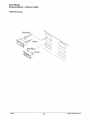
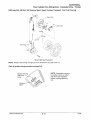
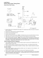
Twin Cylinder Fan COl Ignition - Exploded View - Timing
1999 Indy 340, 340 Dlx, 340 Touring, Sport, Sport Touring, Transport, Trail, Trail Touring
Stator Plate
Lighting Coil
CDI Control Unit
180 and 200 Watt Pulseless
NOTE: Always verify timing of engine at room temperature only (68° F/20° C).
Refer to ignition timing procedure on page 9.22.
NOTE: Acceptable variance
is usually one line on either
side of the dial indicated
blower housing stationary
line.
Blower Housing
Stationary
Lines
Polaris Industries Inc.
9.15
10/98
ELECTRICAL
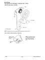
Twin Cylinder Fan COl Ignition - Exploded View -Timing
1999 XCF, Super Sport, Trail RMK
Stator
~
~~\
fP~~
qp~,
o. . .
CDI System
~
~ ~
·~
"
I
RFI Caps
Ignition Coil
240 Watt System
NOTE: Always verify timing of engine at room temperature only (68° F/20° C).
Refer to ignition timing procedure on page 9.22.
NOTE: Acceptable variance
is usually one line on either
side of the dial indicated
blower housing stationary
line.
Blower Housing
Stationary
Lines
Flywheel
Mark
10/98
9.16
Polaris Industries Inc.
ELECTRICAL
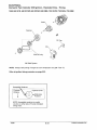
Fuji Twin Cylinder Liquid CDI Ignition - Exploded View -Timing
1999 Indy 500, 500 RMK, 500 Classic, Classic Touring, Widetrak LX
Lighting Coil
200 Watt System
NOTE: Always verify timing of engine at room temperature only (68° F/20° C).
Refer to ignition timing procedure on page 9.22.
Acceptable Variance
Flywheel
Rotation
!
Flywheel Lines
Stationary
Pointers
NOTE: Acceptable variance is usually
one line on either side of the dial indicated
timing mark.
Polaris Industries Inc.
9.17
10/98
ELECTRICAL
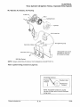
Domestic Twin Cylinder CDI Ignition - Exploded View -Timing
1999 440 XCR, 500 XC/SP, 600 XC/SP, 600 RMK, 700 XC/SP, 700 SKS, 700 RMK
Stator~&
Flywheel
0
~
~!},
<f?
©~
~~a
·---------,
:
I
I
1
0
I
( ) :
~ ~---------:~
CDI~ RF~~
~
600/700 only
280 Watt System
NOTE: Always verify timing of engine at room temperature only (68° F/20° C).
Refer to ignition timing procedure on page 9.22.
Acceptable Variance
Flywheel
Rotation
t
Flywheel Lines
Stationary
Pointers
NOTE: Acceptable variance is usually
one line on either side of the dial indicated
timing mark.
10/98
9.18
Polaris Industries Inc.
ELECTRICAL
Three Cylinder CDI Ignition Timing - Exploded View (Typical)
XLT Special, XLT Classic, XLT Touring
Pulser Coil
Stator
*Lighting/Exciter
COl Control Box
*The Exciter Coil can be
identified by wire color
and smaller windings.
280 Watt System
NOTE: Always verify timing of engine at room temperature only (68° F/20° C).
Refer to ignition timing procedure on page 9.22.
w
Acceptabl( Variance
Flywheel \
Rotation
!
Flywheel Lines
-
Stationary
Pointers
NOTE: Acceptable variance is usually
one line on either side of the dial indicated
timing mark.
Polaris Industries Inc.
9.19
10/98
ELECTRICAL
Three Cylinder COl Ignition - Exploded View
1999 700 XCR, 800 XCR
Stator
*Lighting/Exciter
CDI Control Box
*The Exciter Coil can be
identified by wire color
and smaller windings.
Secondary Coils
280 Watt System
NOTE: Always verify timing of engine at room temperature only (68° F/20° C) with TPS unplugged.
Refer to ignition timing procedure on page 9.22.
Acceptable Variance
Flywheel
Rotation
~
Flywheel Lines
Stationary
Pointers
NOTE: Acceptable variance is usually
one line on either side of the dial indicated
timing mark.
10/98
9.20
Polaris Industries Inc.
ELECTRICAL
CDI Ignition Timing
Timing Procedure - All Models
NOTE: Always check ignition timing with the engine at room temperature only (20°C/68°F).
1.
Refer to the timing specification charts at the beginning of this section to determine the proper ignition timing
for the engine you are working on.
2.
Use a dial indicator to place the piston in the proper timing position and mark the flywheel at this point (follow
procedure on page 9.7).
3.
Connect an accurate tachometer and a good quality timing light to the engine according to manufacturer's
instructions. Disconnect the TPS (Throttle Position Sensor) connector from carburetor on 700 XCR and BOO
XCR.
4.
Start engine and increase RPM to the point
specified in the timing specification chart on page
9.1 (1750, 3000, 3250). Hold the throttle to
maintain specified timing RPM.
5. Point the timing light at the timing inspection hole.
6. With your head positioned so there is a straight
line between your eye, the stationary pointer and
the crankshaft center line, note the relative
position between the marked flywheel line and the
stationary pointer. If the stationary pointer is
aligned with the mark made in Step 2, (or within
the acceptable ± variance) the timing is correct.
7. If the pointer is outside the variance, the stator will
have to be rotated either with crankshaft rotation
(to retard the timing) or against rotation to
advance it.
NOTE: Rotate stator plate approximately the same
distance as the marks must move.
NOTE: In most cases, the recoil starter housing, recoil drive hub, and flywheel must be removed to loosen the stator bolts and change the timing. On some
engines, the stator plate retaining screws can be accessed through the flywheel.
8.
Torque stator plate screws and flywheel nut to
specified torque. Apply Loctite 262 (red) to
crankshaft flywheel taper if required. Refer to the
Specifications section for torque specifications
and flywheel installation procedure for engine
type.
Polaris Industries Inc.
9.21
Acceptable Variance
Flywheel
Rotation
!
NOTE: Acceptable variance is usually
one line on either side of the dial indicated
timing mark.
Liquid Cooled
Blower Housing
Stationa
Lines
Flywheel
Mark
Fan Cooled
10/98
Due to the high RPM necessary and the possible danger involved, special care must be obseNed whenever performing an operating RPM timing check to avoid serious personal injury.
This check need not be performed unless symptoms leading to poor performance and possible engine damage
are present.
•
Never operate the engine with the clutch guard open or removed.
•
Do not stand over or around the clutch while performing this test.
•
Perform the test as quickly as possible. Avoid prolonged periods of engine free-rev.
Operating RPM Timing Test Procedure
1.
Using the charts at the beginning of this unit, determine the ignition advance BTDC at the operating RPM.
2.
Remove the mag side spark plug and install a dial indicator in that cylinder.
3.
Zero the dial indicator as explained on page 9.6.
4.
Turn the crankshaft in the opposite direction of rotation to a point approximately .1 00" (2.5 mm) before the
operating ignition timing point.
5.
Turn the crankshaft in the proper direction of rotation until the dial indicator shows the proper piston position
BTDC for operating RPM ignition timing. NOTE: The charts only indicate degrees BTDC. This figure must be
converted using the tables on page 9.14. Example: The operating timing and RPM for an engine is 16° at
7500 RPM. Using the chart, 16° on this engine is .058 BTDC at 7500 RPM. Using a properly installed and
zeroed dial indicator, back the engine up to approximately .150 BTDC. Then rotate the crank in the proper
direction of rotation to .058 BTDC.
6.
While holding the crankshaft at the ignition timing point (as shown on dial indicator), make a timing mark on the
flywheel or fan blade using a piece of chalk or marker.
7.
Remove the dial indicator and reinstall spark plug.
8.
Start the engine. Advance and hold the throttle at the operating RPM specified on the charts. View the timing
mark with the timing light. The marks should be between the allowable +1- variance indicated on the operating
RPM timing specification.
9.
If the operating RPM timing greatly varies from the specification, but the standard ignition timing (1750, 3000,
or 3250 RPM) is correct, refer to the ignition troubleshooting section in this unit for corrective action.
10/98
9.22
Polaris Industries Inc.
ELECTRICAL
Battery Service
Preparing a New Battery for Service
To ensure maximum service life and performance from a battery, it must have proper initial servicing. To service
a new battery, the following steps must be taken. NOTE: Do not service the battery unless it will be put into regular
service within 30 days.
1.
Remove vent plug from vent fitting.
2.
Fill battery with electrolyte to the upper level marks on the case.
3.
Set battery aside and allow it to cool and stabilize for 30 minutes.
4.
Add electrolyte to bring the level back to the upper level mark on the case. NOTE: This is the last time that
electrolyte should be added. If the level becomes low after this point, add only distilled water.
5.
Charge battery at 1/10 of its amp/hour rating.
Example:1/10 of 9 amp battery= .9 amps, 1/10 of 14 amp battery= 1.4 amps, 1/10 of 18 amp battery= 1.8
amps (recommended charging rates).
6.
Check specific gravity of each cell with a hydrometer to ensure each has a reading of 1.270 or higher.
Battery Testing
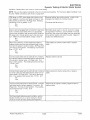
There are three easy tests which can determine battery condition. Whenever the complaint is related to either
the starting or charging systems, the battery should be checked first.
Lead-acid batteries should be kept at or as near full charge as possible. If the battery is stored or used in a partially
charged condition, hard crystal sulfation will form on the plates, reducing their efficiency and possibly ruining the
battery.
Open Circuit Voltage Test (OCV)
Battery voltage should be checked with a digital multitester. Readings of 12.6 or less require further battery testing
and charging.
Specific Gravity Test
A tool such as the battery hydrometer (PN 2870836) can be used to measure electrolyte strength or specific gravity. As the battery goes through the charge/discharge cycle, the electrolyte goes from a heavy , more acidic state
at full charge to a light, more water state when discharged. The hydrometer can measure state of charge and
differences between cells in a multi-cell battery. Readings of 1.270 or greater should be observed in a fully
charged battery. Differences of more than .025 between the lowest and highest cell readings indicate a need to
replace the battery.
State Of Charge
Conventional
Lead-acid
Yumacron
Type
100% Charged
12.60V
12.70V
75% Charged
12.40V
12.50V
50% Charged
12.10V
12.20V
25% Charged
11.90V
12.0V
0% Charged
Less Than
11.80V
Less Than
11.9V
State Of Charge*
Conventional
Lead-acid
Yumacron
Type
100% Charged
1.265
1.275
75% Charged
1.210
1.225
50% Charged
1.160
1.175
25% Charged
1.120
1.135
0% Charged
Less Than
1.100
Less Than
1.115
*at 80° F
NOTE: Subtract .01 from the specific gravity for electrolyte at 40° F and compare these values to the chart.
Polaris Industries Inc.
9.23
10/98
ELECTRICAL
Battery Service
Load Test
NOTE: This test can only be performed on machines equipped with electric start. This test cannot be performed
if the engine or starting system is not working properly.
A battery may indicate a fully charge condition on the OCV test and the specific gravity test, but still not have the
storage capacity necessary to properly function in the electrical system. For this reason, a battery capacity or
load test should be conducted whenever poor battery performance is encountered.
To perform the test, hook a multitester to the battery in the same manner as in the OCV test. The reading should
be 12.6 volts or greater. Engage the electric starter and view the registered battery voltage while cranking the
engine. Continue the test for 15 seconds. During this cranking period, the observed voltage should not drop below
9.5 volts. If the beginning voltage is 12.6 or higher and the cranking voltage drops below 9.5 volts during the test,
replace the battery.
Refilling a Low Battery
The normal charge/discharge cycle of a battery causes the cells to give off gases. These gases, hydrogen and
oxygen, are the components of water. Because of the loss of these gases and the lowering of the electrolyte level,
it will be necessary to add pure, clean distilled water to bring the fluid to the proper level. After filling, charge the
battery to raise the specific gravity to the fully charged position (1.270 or greater).
Off Season Storage
To prevent battery damage during extended periods of non-use, the following basic maintenance items must be
performed.
1.
Remove battery from machine and wash the case and battery tray with a mild solution of baking soda and
water. Rinse with lots of fresh water after cleaning. CAUTION: Do not allow any of the baking soda solution to
enter the battery or the acid will be neutralized.
Using a wire brush or knife, remove any corrosion from the cables and terminals.
2.
3.
4.
Make sure the electrolyte is at the proper level. Add distilled water if necessary.
Charge at a rate no greater than 1/10 of the battery's amp/hr capacity until the electrolyte's specific gravity
reaches 1.270 or greater.
5.
The battery may be stored either in the machine with the cables disconnected, or on a piece of wood in a cool
place. NOTE: Stored batteries lose their charge at the rate of 1% per day. They should be fully recharged
every 30 to 60 days during a non-use period. If stored during winter months, the electrolyte will freeze at
higher temperatures as the battery discharges. The chart indicates freezing points by specific gravity.
Specific Gravity of Electrolyte
Freezing Point
1.265
-75° F
1.225
-35° F
1.200
-17" F
1.150
+5° F
1.100
+18° F
1.050
+27" F
A WARNING
Battery electrolyte is poisonous. It contains acid!
Serious burns can result from contact with the skin,
eyes, or clothing.
ANTIDOTE:
Charging Procedure
Charge battery with a charger no larger than 1/10 of
the battery's amp/hr rating for as many hours as needed to raise the specific gravity to 1.270 or greater.
A
WARNING
The gases given off by a battery are explosive. Any
spark or open flame near a battery can cause an explosion which will spray battery acid on anyone close to
it. If battery acid gets on anyone, wash the affected
area with large quantities of cool water and seek immediate medical attention.
10/98
9.24
EXTERNAL: Flush with water.
INTERNAL: Drink large quantities of water or milk.
Follow with milk of magnesia, beaten egg, or vegetable oil. Call physician immediately.
EYES: Flush with water for 15 minutes and get prompt
medical attention.
Batteries produce explosive gases. Keep sparks,
flame, cigarettes, etc. away. Ventilate when charging
or using in closed space. Always shield eyes when
working near batteries.
KEEP OUT OF REACH OF CHILDREN.
Polaris Industries Inc.
ELECTRICAL
Dynamic Testing of Electric Starter System
Condition: Starter fails to turn motor or motor turns slowly.
NOTE: Be sure the engine crankshaft is free to turn before proceeding. For this test a digital multitester must
be used. Meter connections are shown on page 9.24.
With tester on VDC, place tester black lead on battery negative (-)terminal and tester red lead on battery positive (+)terminal. (A) Page 9.26. Reading
should be 12.6V or greater. Is it?
No_,
Yest
Remove battery, test and/or service. Install a fully
charged shop battery to continue the test.
Disconnect red engagement coil wire from start solenoid. Connect black tester wire to an appropriate
ground and red lead to red harness wire at solenoid.
(F) page 9.26. Rotate ignition key to the start position. Meter should read battery voltage. Does it?
NO->
Yest
With black tester lead on ground, check for voltage
at large relay in terminal, circuit breaker in and out
terminals, and across both sides (red and red/white)
of the ignition switch with switch on start. Repair or
replace any defective parts.
Reconnect solenoid, connect tester black lead to
battery positive terminal and red tester lead to solenoid end of battery to solenoid cable. (B) Page 9.26.
Turn key to start position. The reading must be less
than .1 V DC. Is it?
NO->
Yest
Clean battery to solenoid cable ends or replace
cable.
Connect black tester lead to solenoid end of battery
to solenoid cable and red tester lead to solenoid end
of solenoid to starter cable. (C) Page 9.26. Turn
key to start position. The reading must be less than
.1VDC. lsit?
No_,
Yest
Replace starter solenoid.
Connect black tester lead to solenoid end of solenoid
to starter cable and red tester lead to starter end of
same cable. (D) Page 9.26. Turn key to start position. The reading must be less than .1 V DC. Is it?
No_,
Yest
Clean solenoid to starter cable ends or replace
cable.
Connect black tester lead to starter frame. Connect
red tester lead to battery negative (-)terminal. (E)
Page 9.26. Turn key to start position. The reading
should be less than .1 V DC. Is it?
NO->
Yest
Clean ends of engine to battery negative cable or
replace cable.
(Continue with left column)
If all these tests indicate a good condition, yet the
starter still fails to turn, or turns slowly, the starter
must be remove for static testing and inspection.
Polaris Industries Inc.
9.25
10/98
ELECTRICAL
Electric Starter System Testing (Static)
Starter Motor Static Testing
IGNITION
SWITCH
IGNITION SWITCH
SYSTEM
BAN- GRO\JND
IGNITION WIRE COLORS
G TERMINAL · BROWN · GROUND
fl TERMINAL · RED · flATTERY
M TERMINAL · BLACK - IGNITION
S TERMINAL - RED/WHITE · STARTER
OFF
RUN
~:
START
::~:
A
B
R/W
S
}J_-,
'u
ALTERNATOR
OUTPUT
r
'
I
-'-
' - - - - - - - R'.W-------f(F) (Disconnect RIW Wire)
R
(.C)
CIRCUIT BREAKER
18 liMP!
IGNITION SWITCH
li"'""--~-H-
_________
{8)
'
'
''
STARTER RELAY
CHASSIS GND
1
COLOR CODE
A ' RED
BAN = BROWN
flLK = BLACK
Y ' YELLOW
R/W = RED WITH WHITE TRACER
,----------(E) _________ ! I
I
I
I
ENGINE GND
-=-
I
! --=I
BATTERY
"':""
1
I
t_.S:t!il..!'!.E_G_tJQ. _______ _!
A-E See page 9.25
1.
Remove starter motor and disassemble. (See page 9.27 for exploded view) Mark end covers and housing for
proper reassembly.
2.
Remove pinion retaining snap ring, spring and pinion gear.
3.
Remove brush end bushing dust cover.
4.
Remove housing through bolts.
5.
Slide brush end frame off end of starter. NOTE: The electrical input post must stay with the field coil housing.
6.
Slide positive brush springs to the side, pull brushes out of their guides and remove brush plate.
7.
Clean and inspect starter components. NOTE: Some cleaning solvents may damage the insulation in the
starter. Care should be exercised when selecting an appropriate solvent. The brushes must slide freely in
their holders. If the commutator needs cleaning, use only an electrical contact cleaner and/or a non-metallic
grit sandpaper. Replace brush assembly when worn to 5/16" (.8 em) or less.
Starter Housing and Field Coil Inspection
1.
Using a digital multitester, measure resistance between starter input terminal and insulated brushes. The
reading should be .3 ohms or less.
2.
Measure resistance between insulated brushes and field coil housing. The reading should be infinite.
3.
Inspect insulated brush wire and field coil insulation for damage. Repair or replace components as required.
Armature Testing
1.
Using a digital multitester, measure resistance between each of the segments of the commutator. The
reading should indicate .3 ohms or less.
2.
Measure resistance between commutator and armature shaft. Reading should be infinity.
3.
Place armature in a growler. With the growler on, position a hacksaw blade lengthwise 1/8" (.03 em) above
armature coil laminates. Rotate armature 360°. If hacksaw blade is drawn to the armature on any pole, the
armature is shorted and must be replaced.
10/98
9.26
Polaris Industries Inc.
ELECTRICAL
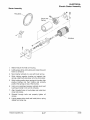
Electric Starter Assembly
Starter Assembly
Ring Gear
ffi~
~w
/
{
G~
® ®
Armature
1.
Slide armature into field coil housing.
2.
Lightly grease drive end bushing and install drive end
frame on armature.
3.
Mount starter vertically in a vice with brush end up.
4.
While holding negative brushes out against their
springs, slide brush plate down onto the commutator.
5.
While holding positive brush springs to the side, slide
positive brushes into their holders and correctly
position the springs on top of the brushes.
6.
Using a non-petroleum grease, lubricate brush end
bushing and slide it onto end of armature.
7.
Align threaded holes in brush plate and install dust
cover and screws.
8.
Reinstall through bolts and properly tighten all
screws.
9.
Lightly grease pinion shaft and install pinion, spring
stopper and snap ring.
Polaris Industries Inc.
9.27
10/98
ELECTRICAL
Starter Installation
Starter Solenoid Bench Test
The only test which can be done on the bench is the pull
in coil resistance, which should be 3.4 ohms.
Starter Installation
1.
Position starter motor so there is no less than .1 00"
clearance between the ring gear and the starter
motor pinion gear.
2.
Torque through
specification.
3.
Torque 8mm (drive end) mount bolts to specification.
4.
Torque 6mm (brush end) bracket to specification.
bolt mount bracket nuts to
Starter Pinion
Gear
Unregulated Voltage - continued
1.
Test resistance of lighting coil and compare to
specifications in the model specific wiring diagram.
Reminder: Meter resistance must be subtracted from
reading.
NOTE: 0.3 to 0.5 ohms may be less than the internal resistance of your meter leads or meter. Before measuring
the stator resistance, short the meter leads together and read the display and record this measurement. Subtract
this reading from the stator resistance readings.
EXAMPLE: Short meter leads together, meter reads 0.7 ohms. Measure stator resistance, meter reads 1.10
ohms. Subtract 0.7 ohms (meter/lead resistance) from 1.10 ohms (reading obtained when checking yellow lead
to brown lead). True reading is: 1.10 ohms (observed reading when checking stator)
-0.7 ohms (meter/lead resistance)
0.4 ohms (true stator resistance)
=
10/98
9.28
Polaris Industries Inc.
ELECTRICAL
Lighting System Output
Unregulated Voltage - continued
2.
3.
Turn the multitester dial to the Volts AC (Vr-v) position.
Disconnect the alternator to main harness connector at
engine.
4.
Connect one of the tester leads to the yellow alternator
wire and the other lead to the brown alternator wire.
NOTE: On floating alternators, the yellow/red stator
wire should connect to the brown stator wire. If it does
not, the system will not have a ground and will not
operate.
Start the engine. While observing the voltage reading,
increase the engine speed to about 3000 RPM.
Readings of between 15 and 45 VAC are considered
normal.
5.
( 15-45 VAC)
0
+
Short Circuit Current (AC Amp Test)
1.
2.
3.
4.
5.
Turn multitester dial to Ar-v.
Connect red lead to 1OA terminal.
Connect black lead to Com (-) meter terminal.
Disconnect lighting/charge coil wires from system.
Connect meter leads to coil wires leading to stator coils.
Start and idle engine. Readings should be above 5
amps. Refer to Amps AC on page 9.4.
Regulated Voltage
1.
2.
Connect the alternator to main harness connector.
Insert one of the tester leads along the side of the yellow
regulator wire connector between the insulation and the
terminal.
3. Ground the other tester lead.
4. Start engine and observe headlight output. Increase
engine RPM. If the headlights seem dim above 3500
RPM, let the engine return to idle and disconnect the
yellow wire from the regulator. Carefully observe the
voltage reading. Do not allow voltage to increase above
14.0 volts.
5. Slowly increase RPM. Voltage above 12 volts at 2500 3000 and a bright headlight, indicates a good lighting
coil. Voltage below 10 volts at 3000 indicates excessive
system loads, poor flywheel magnets, lighting coil
problems, or wires harness problems. Check for
partially grounded (shorted) yellow wire.
6. Reconnect the yellow regulator wire and increase the
RPM. If the headlight was bright with the regulator
disconnected and dim when connected at the same
RPM, the regulator or regulator ground is at fault.
Polaris Industries Inc.
9.29
10/98
ELECTRICAL
Alternator Output- Pulse System
2-pulse, 3-pulse, 6 pulse Alternators
The difference between a 2 pulse, 3 pulse, and 6 pulse alternator system is the number of AC sine waves created
by the alternator in one revolution of the crankshaft. For example, on a 6 pulse system, the alternator will create 6
pulses, or 6 complete AC sine waves, in one crankshaft revolution. The tachometer reads these sine waves,
therefore giving you accurate RPM readings. A 3 pulse tachometer cannot be used on a 6 pulse system. If this is
done, the tachometer will read double RPM. Refer to the following text for applications.
All Polaris Snowmobiles:
All Fuji single cylinder and twin cylinder engines . . . . . . . . . . . . . . . . . . . . .
All Polaris Domestic twin cylinder engines/1999 440 & 550 fan cooled . .
Early model three cylinder engines (500, 600, 650, 750, early 800) . . . .
Late model three cylinder engines (580, 600, 680, 700, 800) ..........
2
6
3
6
pulse
pulse
pulse
pulse
All Polaris ATVs:
All 150 watt alternators and earlier ..... 2 pulse
All 200 watt and 250 watt ............. 6 pulse
All Polaris PWC:
All PWC ...... 6 pulse
6 Pulse
3 Pulse
2 Pulse
Tachometers:
Tachometers for snowmobiles will have an identification marking on the back side. For example: The tachomter
for a 500 XC will have "6 pulse" (or 6P) written on it.
10/98
9.30
Polaris Industries Inc.
ELECTRICAL
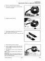
Typical Exciter, Pulser or Lighting Coil Replacement
1.
Remove coil retaining screws and spacers.
2.
Using a pliers, remove epoxy from solder joints (A)
on the coil to be replaced.
3.
Unsolder connection from coil.
4.
Clean solder terminals (B) on the replacement coil
and re-solder to their proper wires.
NOTE: Always position with numbers towards the outsid1
5.
Reinstall retaining screws and spacers.
6.
Using a moisture-proof sealant, seal solder joints
as shown. NOTE: All soldering must be done using
rosin core solder.
7.
Test resistance of each coil prior to stator plate
installation.
NOTE: Lighting and pulseless coils are replaced in a
similar manner.
IMPORTANT: After the stator plate is reinstalled on the
engine, check placement of all coil leads to prevent possible contact with the flywheel.
Polaris Industries Inc.
9.31
10/98
ELECTRICAL
Electrical Testing
Headlight Bulb Filament Continuity Test
1.
Turn the Multitester dial to the ohms (Q) position.
2.
Disconnect the wire harness from the headlight bulb.
3.
Viewing the end of the bulb with the terminal blades at
the 9, 12 and 3 o'clock position, connect the black
multitester lead to the 9 o'clock blade.
4.
Touch the red tester lead to the 12 o'clock terminal and
then to the 3 o'clock terminal, noting the resistance
value of each. A reading of between 2 and 5 ohms is
good. An open reading indicates a bad element.
Hi/Lo Beam Switch Testing
1.
Set the multitester dial to the ohms (Q) position.
2.
If the Hi/Lo switch has not been removed from the
machine, disconnect the switch to harness plug in
connector.
3.
With the Hi/Lo switch in the La beam position, check the
resistance between the yellow and the green switch
wires. The reading should be less than .4 ohms.
4.
Turn the Hi!Lo switch to the Hi beam position and the
multitester should indicate an open circuit (OL)
reading.
5.
Move one of the tester leads from the green to the red
switch wire. The multitester should now read less than
.4 ohms.
6.
Turn the Hi!Lo Switch back to the La beam position and
the meter should again read an open circuit (OL}.
Grn
Yel
Yei/Rd
Seat Harness Troubleshooting
High/Low Switch
1.
Remove the taillight lens.
2.
Remove the two taillight bulbs and the brakelight bulb.
3.
Separate the seat harness from the main harness by
unplugging the connector at the right rear of the tank.
4.
With the multitester dial set on ohms (Q) connect either
meter test lead to the brown seat harness wire.
5.
Touch the other tester lead to first the yellow wire and
then the orange wire. Observe the readings. Readings
other than an open circuit indicate a shorted harness or
bulb socket. NOTE: The bulb socket tangs sometimes
short to ground with the bulb removed.
6.
Check between the yellow and orange wires in the
same manner to check for a short between the brake
and running lights. If damaged wiring is found, remove
the seat.
7.
Tip the seat over and remove the right side seat cover
staples. Locate and repair the harness problem.
8.
Reinstall the staples and re-check the seat harness.
10/98
9.32
Polaris Industries Inc.
ELECTRICAL
Electrical Testing
Ignition Switch Testing (Non-Electric Start)
1.
2.
3.
Set the multitester dial to the ohms (.Q) position.
Connect one of the tester leads to either of the switch
terminals and the other tester lead to the other switch
terminal.
With the switch off, the reading should be less than .4
ohms. With the switch on, the reading must be an open
circuit (OL).
Check the resistance between each of the switch
terminals and the switch body. With the switch still in the
on position, there must be an open circuit (OL) reading.
Readings other than those listed indicate a defective
switch.
Off
Blk
I I
Brn
On
!
Ignition Switch
Ignition Switch Testing (Electric Start Models)
NOTE: Refer to the appropriate model and year wiring
diagram for ignition switch wire colors and connections.
1.
Disconnect wires. Set the multitester dial to the ohms
(.Q) position.
2.
With the key in the off position, check the resistance
between the G (Ground, brown) terminal and the M
(Mag, black) terminal. This reading must be less than .4
ohms.
3.
Turn the key to the on position. The multitester should
now read an open circuit (OL).
4.
Move the tester lead from the G terminal to the switch
housing and re-check the reading. It should also be an
open circuit (OL).
5.
Place one of the tester leads on the B (Battery, red)
terminal and the other tester lead on the S (Starter, blue)
terminal. With the key in the on position, there must be
an open circuit (OL) reading.
6.
Turn the key to the start position. The reading should be
less than .4 ohms. Readings other than the ones listed
indicate a defective switch.
Off
Brn
Blk
R
On
Start
T
•
~~
~
R/W
Ignition Switch - Electric Start
Polaris Industries Inc.
9.33
10/98
ELECTRICAL
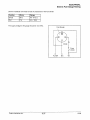
Coolant High Temperature Indicator Testing
Circuit
Power
In
Blk!W------..
- Yel------,1
II
Temp
Ground the Black/White wire here
(with the engine running) to test
the light.
II
Engine
Ground
The indicator light is controlled by a temperature/warning switch installed into the engine cooling system. When
engine coolant temperature reaches approximately 205° F, the switch closes, completing the circuit through the
indicator light to ground. The system should be tested periodically for proper operation.
Lamp Circuit Test
1.
Remove wire from temperature sensing switch located under thermostat housing.
2.
With engine idling, ground wire to engine. The temperature warning lamp on the console should light. If not,
replace the lamp assembly or inspect wiring for shorts or open circuit.
Temp Light Temperature Sensor Test
The temperature/warning switch is normally open.
1.
Set the multitester on the ohms (Q) scale.
2.
Disconnect the lamp wire.
3.
Connect one test probe to the switch terminal and the other to engine ground. The meter should show an open
circuit (OL). This indicates a normally open switch. If the switch were heated to approximately 205° F, the
contact in the switch would close and the reading would be less than .4 ohms.
If attempting to heat the sensor to close the contacts, heat only in a water bath. Never subject the sensor to an
open flame to attempt to close the contacts as sensor damage will result.
10/98
9.34
Polaris Industries Inc.
ELECTRICAL
Speed Control Assurance Operation
Insulator
Auxiliary Kill
Switch Contacts
Ignition Primary
Engine Ground
B
Throttle Control
Cutaway
The speed control assurance consists of two series connected switches. If one or both switch plungers are positioned inward, the circuit is open and the engine will run.
At idle, with the throttle lever properly adjusted, the bottom switch circuit is open and the plunger is inward. The
top switch circuit is closed, and the plunger is outward. The speed control circuit is open, allowing the engine to
run.
As the throttle lever is actuated to an off idle position, the top switch circuit is opened (plunger in) and the bottom
switch circuit is closed (plunger out). The speed control circuit is still open, allowing the engine to run.
In the event the carburetor or controls malfunction and allow the throttle cable to become slack, the circuit will
close (both switch plungers out), grounding the ignition system and causing the engine to stop.
Speed Control Assurance Adjustment
Throttle lever free play must always provide a specified
clearance between throttle lever (A) and throttle block (B).
This clearance is controlled by the throttle cable sleeve(s)
and the idle speed screw(s).
Throttle Lever Freeplay Regular Throttle- .010 • .030" (.25- .8 mm)
EZ Throttle - .050 - .060" (1.27 - 1.5 mm)
If the idle speed screw(s) is adjusted inward and the cable
sleeve(s) is not adjusted to take up the throttle lever to
throttle block clearance, the engine may misfire or kill upon
initial throttle opening.
After any idle speed adjustments are made, the throttle lever to throttle block clearance and oil pump adjustment
must be checked and adjusted.
NOTE: When adjustments are made on models which have more than one carburetor, refer to Section 6, Carburetion, for proper carburetor synchronization adjustments.
Polaris Industries Inc.
9.35
10/98
ELECTRICAL
Speed Control Assurance Testing
1.
Set the multitester in the ohms (Q) position.
2.
Disconnect the switch harness from the main wire harness.
3.
Connect the two multitester leads to the two switch wires.
Test 1 - Open Circuit - Run
With the auxiliary shut-off switch in the ON position, the
multitester should read an open circuit (OL). As the throttle
lever is moved from idle to off idle, the tester should continue
to read an open circuit. If the tester fluctuates and the
throttle lever to throttle block clearance is adjusted properly,
the switch assembly must be replaced.
Test 2 - Closed Circuit - Kill
The two speed control switches must make a complete circuit to kill the engine. To check the switches, pull the throttle
lever out away from the throttle block. With the switch plungers outward and the auxiliary shut-off switch in the ON position, the multitester must read less than .4 ohms resistance.
Inspect wires and repair if damaged, or replace switch assembly.
Test 3 - Auxiliary Shut-Off
The multitester should read less than .4 ohms in the OFF position and an open circuit in the the ON position.
Inspect wires and repair if damaged, or replace switch assembly.
Speed Control Assurance Replacement
Auxiliary shut-off and speed control assurance switches are connected and replaced as a unit from the back side
of the throttle block.
1.
Remove the handlebar pad and/or throttle block backing plate.
2.
Slide oat the auxiliary shut-off portion of the switch.
3.
Remove the two screws securing the two speed control assurance switches.
4.
Remove the switches noting their placement in the throttle block.
5.
Replace the assembly and check its operation.
10/98
9.36
Polaris Industries Inc.
ELECTRICAL
Electric Fuel Gauge Testing
Use the multitester ohmmeter to test the resistance of the fuel sender.
Position
Ohms
Range
Empty
95Q
Full
7Q
n
4.5- 13 n
90-97.5
The supply voltage to the gauge should be 13.5 VAC.
Fuel Gauge
Fuse
(0.2A}
Pur/Wh
Polaris Industries Inc.
9.37
Brn
Yel
10/98
ELECTRICAL
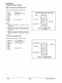
Handlebar Warmer Testing
High-Low Handwarmer Toggle Switch
Below are the correct wire to PIN numbers:
1.
2.
3.
4.
5.
6.
7.
8.
Blue
Yellow
Blue/Red
Blank
Blank
Blank
Brown
Blank
-
High Circuit
Regulated Power (A.C.)
Low Circuit
-
Ground Circuit
HANDLEBAR HARNESS WIRE CONN.
BLUE
YELLOW
BROWN
Testing
1.
2.
3.
BLUE/RED
Disconnect handwarmer connector at the
handwarmer.
Measure the low range resistance between the
Blue and Brown wires. The resistance should
be 19.2 D..
Measure the high range resistance between the
Brown and Blue/Red. The resistance should be
SWITCH- HANDWARMER
HI-LOW
9.6Q.
Thumbwarmer Toggle Switch
Below are the correct wire to PIN numbers:
1.
2.
3.
4.
5.
6.
7.
8.
White/Gray
Yellow
White/Gray
Blank
Blank
Blank
Brown
Blank
-
To Thumbwarmer
Regulated Power (A.C.)
To Thumbwarmer
WHITE/GRAY
BROWN
YELLOW
-
Ground Circuit
WHITE/GRAY
SWITCH - THUMBWARMER
10/98
9.38
Polaris Industries Inc.
ELECTRICAL
Ignition System Troubleshooting
Condition: No Spark
Disconnect the single black (black/white) wire from the CDI Module to
the ignition kill circuit. Does it have a spark?
Yes-+
Not
Check the ignition switch, wire harness, throttle safety switches
and kill switch for proper adjustment or short to ground. Repair
or replace as necessary.
Disconnect the stator to CDI module wires. Test the resistance values
of the stator coils as per the wiring diagrams. Are the resistance values within specs?
All except 3 cylinders: If the parts of the ignition system under
the flywheel check OK, the only remaining component is the
coii/CDI module assembly. Replace the module with another
with the same CU number. (See ignition data)
All 3 cylinders: Disconnect and check the secondary ignition coil
resistances. Refer to the resistance values listed in wiring
diagrams. If the coil resistance values are within specs, replace
the CDI module.
Yes-+
Not
Isolate which component's resistance is not within specs. Remove
the flywheel and stator. Recheck the resistances; look for pinched or
bare harness wires; or replace the coil. Refer to page 9.31 for coil
replacement procedures.
Condition: Incorrect Advance/Retard
Follow the engine timing procedure for checking running timing at
recommended RPM. Is the timing within limits?
No-+
Yes t
Adjust the ignition timing by rotating the stator plate to correct the
timing. After adjusting the recommended RPM timing, continue
with operating RPM timing if poor performance exists. (Continue
on with left column.) See ignition timing page 9.1.
Follow the engine timing procedure for checking operating RPM timing
from page 9.22. Is the timing within limits?
If the running and operating RPM timing are within limits, no
other testing is necessary.
Yes-+
Not
Remove the ignition kill circuit by disconnecting the single black wire
between the CDI module and the machine harness. Is the timing now
correct?
Check the ignition switch, throttle safety switches, kill switch and
harness for damage which can cause intermittent shorting
problems. Correct the problem.
Yes-+
Not
Verify the correct CDI module by comparing the CU code on the box
to the information listed in the ignition data charts at the beginning of
this section. Is it the right module?
Replace the module with the correct part and readjust the ignition
timing.
-
No-+
Vest
Check the resistance of the coils under the flywheel. Compare these
values on wiring diagram. Are they within limits?
Check the wiring connecting the coils and/or replace the coils as
necessary.
No-+
Vest
If the running RPM timing is within limits but the operating RPM timing
is not acceptable, replace the CDI module.
NOTE: 3 cylinder engines fire three times per revolution. At 7500 RPM the ignition is firing 21 ,500 times per
minute. Use of a timing light not capable of handling these RPMs may provide an incorrect operating RPM timing
reading. Use timing light PN 2870630 or equivalent.
Polaris Industries Inc.
9.39
10/98