1
No. 99MAM024A1
USB-ITPAK
User’s Manual
Read this User’s Manual thoroughly before using the
instrument. After reading, retain it close at hand for future
reference.
Second Edition December 2014 Ver 2.001
First Edition March 2013
Ver 2.000
This manual is subject to change without notice for improvement and other purposes.
© Copyright Mitutoyo Corporation 2010-2014
The product names and company names mentioned in this manual are registered trademarks or
trademarks of their respective companies.
Mitutoyo Software End User License Agreement
IMPORTANT – PLEASE READ THIS MITUTOYO SOFTWARE END USER LICENSE
AGREEMENT ("EULA") CAREFULLY BEFORE USING THE MITUTOYO SOFTWARE
PRODUCTS. THIS EULA SHALL CONSTITUTE A LEGAL AGREEMENT BETWEEN
YOU/CUSTOMER AND MITUTOYO CORPORATION (“MITUTOYO”) FOR THE
MITUTOYO SOFTWARE PRODUCT DISTRIBUTED WITH THIS EULA, WHICH
SOFTWARE PRODUCT INCLUDES, WITHOUT LIMITATION, COMPUTER SOFTWARE
AND MAY ALSO INCLUDE ASSOCIATED MEDIA, PROGRAM DISK(S), DONGLES,
MANUALS, OTHER PRINTED MATERIALS, AND/OR OTHER “ONLINE” OR
ELECTRONIC DOCUMENTATION (COLLECTIVELY, “SOFTWARE PRODUCT”). BY
CLICKING ON THE "ACCEPT" BUTTON, OPENING THE PACKAGE, DOWNLOADING
THE SOFTWARE PRODUCT, INSTALLING THE SOFTWARE PRODUCT ON AND/OR
USING THE EQUIPMENT THAT CONTAINS THIS SOFTWARE PRODUCT, YOU ARE
CONSENTING TO BE BOUND BY THE TERMS OF THIS EULA. IF YOU DO NOT
AGREE TO ALL OF THE TERMS AND CONDITIONS OF THIS EULA, DO NOT CLICK
ON THE “ACCEPT” BUTTON AND DO NOT USE, OPEN OR DOWNLOAD THE
SOFTWARE PRODUCT. THIS SOFTWARE PRODUCT IS LICENSED, NOT SOLD,
SUBJECT TO THE TERMS AND CONDITIONS SET FORTH IN THIS EULA. THE
GRANT OF LICENSE SET FORTH BELOW WILL BE EFFECTIVE ONLY WHEN YOU
AGREE TO ALL TERMS AND CONDITIONS SET FORTH IN THIS EULA.
1
License
Mitutoyo grants to you/customer (“Customer”) a non-transferable and non-exclusive and
limited license to install and use on copy of the Software Product (in object code form only)
on a single computer system, under the terms and conditions of this EULA. In the event
that Customer wishes to use the Software Product on another computer, Customer must
obtain another license therefor.
Customer acknowledges and agrees that (a) Mitutoyo is and shall remain the sole and
exclusive owner of all right, title and interest in and to the Software Product and (b)
Customer has no right, title or interest of any nature whatsoever in and to the Software
Product, except the right to use the Software Product in accordance with and subject to
the terms and conditions of this EULA. All rights not expressly granted herein by Mitutoyo
are reserved by Mitutoyo for the exclusive benefit and use of Mitutoyo and its affiliated and
related companies as Mitutoyo deems appropriate.
2
Restrictions
EXCEPT AS EXPRESSLY AUTHORIZED HEREIN, CUSTOMER SHALL NOT PRINT
OR COPY, IN WHOLE OR IN PART, THE SOFTWARE PRODUCT; MODIFY THE
SOFTWARE PRODUCT; REVERSE COMPILE OR REVERSE ASSEMBLE/ENGINEER
ALL OR ANY PORTION OF THE SOFTWARE PRODUCT; OR RENT, LEASE,
SUBLICENSE, DISTRIBUTE, SELL, OR CREATE DERIVATIVE WORKS OF THE
SOFTWARE PRODUCT.
No. 99MAM024A
i
Customer may permanently transfer all of its rights under this EULA and the Software
Product, on the conditions that (a) Customer notifies Mitutoyo of its intention of transfer
prior to such transfer; (b) Customer retains no copies thereof, (c) Customer transfers all of
the Software Product (including all component parts, the media and printed materials, any
upgrades, this EULA, and, if applicable, the Certificate of Authenticity) to the transferee
and (d) the transferee agrees to abide by all of the terms of this EULA. If the Software
Product is an upgrade, any transfer must include all prior versions of the Software Product
and all of Customer’s rights therein, if any.
3
Copyright
Copyright in and to the Software Product shall remain exclusively with Mitutoyo and/or its
licensors. Customer may not remove, modify or alter any copyright, trademark or any
other intellectual property legend/notice from any part of the Software Product.
4
Limited warranty
If Customer discovers a physical defect in the media on which the Software Product is
distributed, or in a documentation of the Software Product within one year from the date of
original purchase by Customer, Mitutoyo will replace the media or documentation free of
charge. Except for the foregoing, the Software Product is provided “AS IS”; provided
however, that if a malfunction which Mitutoyo judges as fatal defect affecting an intended
material performance or functions of the Software Product within one year from the date of
original purchase by Customer, Mitutoyo will at its option repair such defect or provide
replacement software. This limited warranty extends only to Customer as the original
licensee. Customer's exclusive remedy and the entire liability of Mitutoyo and its suppliers
and related companies under this limited warranty will be, at Mitutoyo's sole and exclusive
option, repair, or replacement as aforesaid.
In no event does Mitutoyo warrant that the Software Product is error free or that Customer
will be able to operate the Software Product without problems or interruptions or that the
Software Product will work in combination with any hardware or application software
products provided by third parties.
This warranty does not apply if the Software Product or any component or element thereof
(or the equipment upon which such Software Product is intended to operate) (a) has been
altered or modified, (b) has not been installed, operated, repaired, or maintained in
accordance with instructions supplied by Mitutoyo, (c) has been subjected to abnormal
physical or electrical stress, misuse, negligence, or accident, or (d) is used in
ultra-hazardous activities.
Any warranty provided by Mitutoyo or its affiliated companies relative to the
equipment/hardware upon which the Software Product is installed shall not expand,
extend or otherwise modify the limited warranty set forth herein or provide any rights to
Customer which are not otherwise expressly set forth herein.
ii
No. 99MAM024A
EXCEPT AS SPECIFIED IN THIS WARRANTY, ALL EXPRESS OR IMPLIED
CONDITIONS, REPRESENTATIONS, AND WARRANTIES OF ANY NATURE
WHATSOEVER INCLUDING, WITHOUT LIMITATION, ANY IMPLIED WARRANTY OF
MERCHANTABILITY, FITNESS FOR A PARTICULAR PURPOSE, NONINFRINGEMENT
OR WARRANTY ARISING FROM A COURSE OF DEALING, USAGE, OR TRADE
PRACTICE, ARE HEREBY EXCLUDED TO THE MAXIMUM EXTENT ALLOWED BY
APPLICABLE LAW.
Customer assumes all responsibility for all results arising out of its selection of the
Software Product to achieve its intended results.
5
Disclaimer
IN NO EVENT WILL MITUTOYO, ITS AFFILIATED AND RELATED COMPANIES AND
SUPPLIERS BE LIABLE FOR ANY LOST REVENUE, PROFIT, OR DATA, OR FOR
SPECIAL, DIRECT, INDIRECT, CONSEQUENTIAL, INCIDENTAL, OR PUNITIVE
DAMAGES HOWEVER CAUSED AND REGARDLESS OF THE THEORY OF LIABILITY
ARISING OUT OF THE USE OF OR INABILITY TO USE THE SOFTWARE PRODUCT
EVEN IF MITUTOYO OR ITS AFFILIATED AND RELATED COMPANIES AND/OR
SUPPLIERS HAVE BEEN ADVISED OF THE POSSIBILITY OF SUCH DAMAGES.
If, notwithstanding the other provisions of this EULA, Mitutoyo is found to be liable to
Customer for any damage or loss which arises out of or is in any way connected with use
of the Software Product by Customer, in no event shall Mitutoyo's and/or its affiliated and
related companies’ and suppliers' liability to Customer, whether in contract, tort (including
negligence), or otherwise, exceed the price paid by Customer for the Software Product
only.
The foregoing limitations shall apply even if the above-stated warranty fails of its essential
purpose.
BECAUSE SOME COUNTRIES, STATES OR JURISDICTIONS DO NOT ALLOW THE
EXCLUSION OR THE LIMITATION OF LIABILITY FOR CONSEQUENTIAL OR
INCIDENTAL DAMAGES, IN SUCH COUNTRIES, STATES OR JURISDICTIONS,
MITUTOYO'S LIABILITY SHALL BE LIMITED TO THE EXTENT PERMITTED BY LAW.
6
Termination
The license under this EULA is effective until terminated. Customer may terminate this
EULA at any time by destroying all copies of the Software Product including all media and
documentation. This EULA will terminate immediately without notice from Mitutoyo if
Customer fails to comply with any provision of this EULA. Upon termination, Customer
must destroy all copies of Software Product including all media and documentation.
No. 99MAM024A
iii
7
Export control
The Software Product is subject to Japanese export control laws as well as any other
applicable export or import control laws and regulations in other countries. Customer
agrees to comply strictly with all such applicable regulations and acknowledges that it has
the responsibility to obtain licenses to export, re-export, or import the Software Product.
8
Miscellaneous
This EULA shall be governed by and construed in accordance with the laws of Japan,
without giving effect to the principles of conflict of law. Customer agrees to submit to the
exclusive jurisdiction of the district courts in Tokyo, Japan with respect to any dispute,
controversy or claim arising out of or relating to this EULA and the parties respective rights
and obligations hereunder. This EULA shall not be governed by the United Nations
Convention on Contracts for the International Sale of Goods, the application which is
expressly excluded.
If any portion hereof is found to be void or unenforceable, the remaining provisions of this
EULA shall remain in full force and effect.
This EULA constitutes the entire agreement between Customer and Mitutoyo with respect
to the subject matter hereof.
Customer shall indemnify, defend and hold harmless Mitutoyo from and against any and
all claims and liability of any nature whatsoever arising out of or in connection with
Customer’s breach of this EULA.
iv
No. 99MAM024A
CONVENTIONS USED IN THIS MANUAL
Types of Notes
The following types of notes are used in this manual to help the operator obtain reliable
measurement data through correct instrument operation.
IMPORTANT
An important note provides information essential to use the product.
You cannot
disregard this note.
An important note is a type of precaution, which if neglected could result in degraded
performance or accuracy, or instrument malfunction/failure.
NOTE
A note provides information to be especially noted or supplemented to use the product.
A note also supplies information to be noted for specific operations (e.g., memory
limitation, instrument configuration, or details that apply to specific versions of a
program).
TIP
A tip is a type of note that helps the user to apply the operation method and procedures
to his or her specific conditions.
A tip also indicates the reference destination if there is information to be referred to.
The specifications and information in this manual are subject to change without notice.
Copyright 2010-2014 Mitutoyo Corporation.
No. 99MAM024A
All rights reserved.
v
Electromagnetic Compatibility
This product complies with the EMC Directive.
Note that in environments where
electromagnetic interference exceeds EMC requirements defined in this directive,
appropriate countermeasures are required to assure the product performance.
• EMC directive
EN61326-1
Immunity test requirement : Clause 6.2 Table 2
Emission limit : Class B
Mitutoyo Corporation
20-1, Sakado 1-Chome, Takatsu-ku, Kawasaki-shi, Kanagawa 213-8533, Japan
http://www.mitutoyo.co.jp
A display value on this product may flicker or disappear temporarily due to electromagnetic
interference caused by electrostatic discharge. However, this product will return to normal
after removing the interference.
External power supply models may not acquire correct measurement data due to
electromagnetic interference acting on the AC or DC power line.
If this is the case, check the circumference of the power line and then perform
measurement again.
External power supply models will be turned off automatically if a brownout occurs.
However, this product will return to normal after the recovery from the low voltage.
Conventions for Describing Software Operation
This software runs on Windows operating systems.
This manual assumes that the reader is familiar with the operation of Windows-based
software. If you are not familiar with the operation of Windows, refer to a Windows
operation manual such as the "Microsoft Windows First Step Guide".
This manual features screen displays and operation explanations for when the software is
used on Windows 7, but the functions and operation method of the software are the same
regardless of the Windows platform.
Microsoft, Windows, Windows Vista and Excel are registered trademarks and/or
trademarks of Microsoft Corporation in the United States and/or other countries.
vi
No. 99MAM024A
Warranty
In the event that this product should prove defective in workmanship or material, within
one year from the date of original purchase for use, it will be repaired or replaced, at
Mitutoyo’s option, free of charge upon its prepaid return to Mitutoyo, without prejudice to
the provisions of the Mitutoyo Software End User License Agreement.
If the product fails or is damaged for any of the following reasons, it will be subject to a
repair charge, even if it is still under warranty.
(a) Failure or damage owing to fair wear and tear.
(b) Failure or damage owing to inappropriate handling, maintenance or repair, or to
unauthorized modification.
(c) Failure or damage owing to transport, dropping, or relocation of the instrument after
purchase.
(d) Failure or damage owing to fire, salt, gas, abnormal voltage, lightning surge, or
natural disaster.
(e) Failure or damage owing to use in combination with hardware or software other than
those designated or permitted by Mitutoyo.
(f)
Failure or damage owing to use in ultra-hazardous activities.
This warranty is effective only where the instrument is properly installed and operated in
conformance with the instructions in this manual within the original country of the
installation.
EXCEPT AS SPECIFIED IN THIS WARRANTY, ALL EXPRESS OR IMPLIED
CONDITIONS,
REPRESENTATIONS,
AND
WARRANTIES
OF
ANY
NATURE
WHATSOEVER INCLUDING, WITHOUT LIMITATION, ANY IMPLIED WARRANTY OF
MERCHANTABILITY, FITNESS FOR A PARTICULAR PURPOSE, NONINFRINGEMENT
OR WARRANTY ARISING FROM A COURSE OF DEALING, USAGE, OR TRADE
PRACTICE, ARE HEREBY EXCLUDED TO THE MAXIMUM EXTENT ALLOWED BY
APPLICABLE LAW.
You assume all responsibility for all results arising out of its selection of this product to
achieve its intended results.
No. 99MAM024A
vii
Export Control Compliance
This Product falls into the Listed-Controlled Goods and/or Listed-Controlled Technologies
(including Programs) under Category 1 through 15 of Separate Table 1 of Export Trade
Control Order or under Category 1 through 15 of Separate Table of Foreign Exchange
Control Order, based on Foreign Exchange and Foreign Trade Law of Japan.
If you intend re-exporting the product from a country other than Japan, re-selling the
product in a country other than Japan, or re-providing the technology (including program),
you shall observe the regulations of your country.
Please contact Mitutoyo prior to such
re-exporting, re-selling or re-providing.
Disposal of Old Electrical & Electronic Equipment
(Applicable in the European Union and other European
countries with separate collection systems)
This symbol on the product or on its packaging is based on WEEE Directive (Directive on
Waste Electrical and Electronic Equipment), which is a regulation in EU member
countries, and this symbol indicates that this product shall not be treated as household
waste.
To reduce the environmental impact and minimize the volume of landfills, please
cooperate in reuse and recycle.
For how to dispose of the product, please contact your dealer or the nearest Mitutoyo
sales office.
viii
No. 99MAM024A
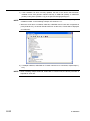
Contents
Mitutoyo Software End User License Agreement ..........................................................................................i
CONVENTIONS USED IN THIS MANUAL ........................................................................................................v
Electromagnetic Compatibility .......................................................................................................................vi
Conventions for Describing Software Operation .........................................................................................vi
Warranty ..........................................................................................................................................................vii
Export Control Compliance ..........................................................................................................................viii
Disposal of Old Electrical & Electronic Equipment (Applicable in the European Union and other
European countries with separate collection systems) ............................................................................viii
1
2
BASIC KNOWLEDGE ........................................................................................................................... 1-1
1.1
Overview ........................................................................................................................................ 1-1
1.2
System Configuration ................................................................................................................... 1-3
1.3
PC Specification Requirements ................................................................................................... 1-5
1.4
Tools that work with USB-ITPAK ................................................................................................. 1-6
1.5
Technical Terms............................................................................................................................. 1-8
1.5.1
Device No. .............................................................................................................................. 1-8
1.5.2
Dedicated VCP driver ............................................................................................................ 1-8
1.5.3
Procedure ............................................................................................................................... 1-8
1.5.4
Setting files ............................................................................................................................ 1-8
1.5.5
Sequential measurement ...................................................................................................... 1-9
1.5.6
Batch measurement .............................................................................................................. 1-9
1.5.7
Individual measurement........................................................................................................ 1-9
1.5.8
Data entry application ........................................................................................................... 1-9
INSTALLATION AND UNINSTALLATION............................................................................................. 2-1
2.1
2.1.1
Installing USB-ITPAK ............................................................................................................. 2-1
2.1.2
Uninstalling USB-ITPAK ........................................................................................................ 2-9
2.2
3
Installing and Uninstalling USB-ITPAK ....................................................................................... 2-1
Installing and Uninstalling the VCP Driver ............................................................................... 2-10
2.2.1
Installing the VCP driver (Windows XP) ............................................................................ 2-10
2.2.2
Installing the VCP driver (Windows 8/8.1 / Windows 7 / Windows Vista) ........................ 2-17
2.2.3
Installing the VCP driver (Windows 2000) ......................................................................... 2-25
2.2.4
Uninstalling the VCP driver (Windows XP) ....................................................................... 2-31
2.2.5
Uninstalling the VCP driver (Windows 8/8.1 / Windows 7 / Windows Vista) .................. 2-32
2.2.6
Uninstalling the VCP driver (Windows 2000) .................................................................... 2-34
STARTUP AND TERMINATION OF USB-ITPAK .................................................................................. 3-1
3.1
Starting up USB-ITPAK ................................................................................................................. 3-1
3.1.1
Connecting the measuring tool and foot switch to the PC ............................................... 3-1
3.1.2
Connecting the USB dongle to the PC ................................................................................ 3-2
No. 99MAM024A
ix
4
3.1.3
Starting up USB-ITPAK .......................................................................................................... 3-3
3.1.4
Exiting USB-ITPAK ................................................................................................................. 3-5
3.1.5
Disconnecting the USB dongle from the PC ....................................................................... 3-5
3.1.6
Disconnecting the measuring tool and foot switch from the PC ...................................... 3-5
MEASUREMENT DATA COLLECTION (BASICS) ............................................................................... 4-1
4.1
General Cautions Regarding Use ................................................................................................ 4-1
4.2
Sequential Measurement (Basics) ............................................................................................... 4-2
4.2.1
Overview ................................................................................................................................. 4-2
4.2.2
Setting ..................................................................................................................................... 4-4
4.2.3
Measurement ........................................................................................................................ 4-12
4.3
4.3.1
Overview ............................................................................................................................... 4-15
4.3.2
Setting ................................................................................................................................... 4-17
4.3.3
Measurement ........................................................................................................................ 4-26
4.4
Individual Measurement (Basics)............................................................................................... 4-29
4.4.1
Overview ............................................................................................................................... 4-29
4.4.2
Setting ................................................................................................................................... 4-31
4.4.3
Measurement ........................................................................................................................ 4-39
4.5
Sequential Measurement (Basics) using U-WAVE ................................................................... 4-42
4.5.1
Overview ............................................................................................................................... 4-42
4.5.2
Setting ................................................................................................................................... 4-44
4.5.3
Measurement ........................................................................................................................ 4-52
4.6
Batch Measurement (Basics) using U-WAVE ........................................................................... 4-55
4.6.1
Overview ............................................................................................................................... 4-55
4.6.2
Setting ................................................................................................................................... 4-57
4.6.3
Measurement ........................................................................................................................ 4-66
4.7
5
Batch Measurement (Basics) ..................................................................................................... 4-15
Individual Measurement (Basics) using U-WAVE ..................................................................... 4-69
4.7.1
Overview ............................................................................................................................... 4-69
4.7.2
Setting ................................................................................................................................... 4-71
4.7.3
Measurement ........................................................................................................................ 4-79
MEASUREMENT DATA COLLECTION (ADVANCED) ......................................................................... 5-1
5.1
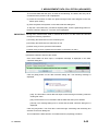
Data Input Request Using Foot Switch ....................................................................................... 5-1
5.1.1
Overview ................................................................................................................................. 5-1
5.1.2
Setting ..................................................................................................................................... 5-4
5.1.3
Measurement ........................................................................................................................ 5-10
5.2
Setting File That Includes Two Procedures .............................................................................. 5-13
5.2.1
5.2.2
Setting ................................................................................................................................... 5-15
5.2.3
Measurement ........................................................................................................................ 5-26
5.3
x
Overview ............................................................................................................................... 5-13
Measurement by Repeating Procedure ..................................................................................... 5-29
5.3.1
Overview ............................................................................................................................... 5-29
5.3.2
Setting ................................................................................................................................... 5-32
5.3.3
Measurement ........................................................................................................................ 5-43
No. 99MAM024A
5.4
5.4.1
Overview ............................................................................................................................... 5-46
5.4.2
Setting ................................................................................................................................... 5-48
5.4.3
Measurement ........................................................................................................................ 5-55
5.5
Data Input to an Optional Application ....................................................................................... 5-58
5.5.1
Overview ............................................................................................................................... 5-58
5.5.2
Setting ................................................................................................................................... 5-60
5.5.3
Measurement ........................................................................................................................ 5-68
5.6
DateTime data entry (When using Excel) .................................................................................. 5-70
5.6.1
Overview ............................................................................................................................... 5-70
5.6.2
Setting ................................................................................................................................... 5-72
5.6.3
Measurement ........................................................................................................................ 5-82
5.7
6
Character Input Using Foot Switch ........................................................................................... 5-46
Timer Job ..................................................................................................................................... 5-86
5.7.1
Overview ............................................................................................................................... 5-86
5.7.2
Setting ................................................................................................................................... 5-88
5.7.3
Measurement ........................................................................................................................ 5-91
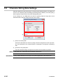
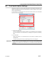
DIALOG BOX CONFIGURATIONS OF USB-ITPAK ............................................................................ 6-1
6.1
Quick Menu .................................................................................................................................... 6-3
6.1.1
[Data collection] button ......................................................................................................... 6-4
6.1.2
[Save (Excel file)] button ....................................................................................................... 6-4
6.1.3
[Save (Text file)] button ......................................................................................................... 6-5
6.2
Main Dialog Box ............................................................................................................................ 6-6
6.2.1
[File] menu .............................................................................................................................. 6-9
6.2.2
[Setting] menu ...................................................................................................................... 6-10
6.2.3
Data Collection menu ...........................................................................................................6-11
6.2.4
[About] menu ........................................................................................................................6-11
6.3
Device Information ...................................................................................................................... 6-12
6.4
Device Information Setting ......................................................................................................... 6-13
6.5
Options ......................................................................................................................................... 6-15
6.6
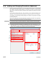
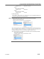
Adding and Changing Procedures (Excel/Sequential or Batch) ............................................ 6-17
6.6.1
Selection of data entry cell range in Excel ........................................................................ 6-20
6.6.2
Cell movement direction & cell displacement interval .................................................... 6-21
6.6.3
Cell address assign rules ................................................................................................... 6-23
6.7
Data Entry Device Settings (Excel/Sequential or Batch) ......................................................... 6-24
6.7.1
[Excel cells assignment] field input ................................................................................... 6-26
6.7.2
Data entry device setting for date and time ...................................................................... 6-27
6.8
Character String Data Settings .................................................................................................. 6-30
6.9
Foot Switch Option Settings ...................................................................................................... 6-31
6.10
Adding and Changing Procedures (Excel/Individual) ............................................................. 6-32
6.11
Data Entry Device Settings (Excel/Individual) .......................................................................... 6-34
6.12
Adding and Changing Procedures (Optional) .......................................................................... 6-36
6.13
Data Entry Device Settings (Optional) ...................................................................................... 6-40
6.14
Data Collection ............................................................................................................................ 6-42
No. 99MAM024A
xi
6.14.1
[Pause/Resume] button ....................................................................................................... 6-44
6.14.2
Resuming operation (For the timer job option) ................................................................ 6-45
6.15
7
Timer Job Option Setting ............................................................................................................ 6-46
COMMUNICATION COMMAND SPECIFICATIONS ............................................................................. 7-1
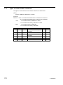
7.1
7.1.1
API of VCP communication ................................................................................................... 7-1
7.1.2
Common specifications of communication commands .................................................... 7-1
7.1.3
Types of communication commands ................................................................................... 7-2
7.2
8
Overview ......................................................................................................................................... 7-1
Format of Communication Commands ....................................................................................... 7-3
7.2.1
Device information request command (V) (down) .............................................................. 7-3
7.2.2
Device information command (1) (up) ................................................................................. 7-3
7.2.3
Measurement data request command (1) (down) ............................................................... 7-3
7.2.4
Measurement data command (0) (up) .................................................................................. 7-4
7.2.5
Foot switch signal command (8) (up) .................................................................................. 7-4
7.2.6
Status command (9) (up) ....................................................................................................... 7-5
APPENDIX ............................................................................................................................................. 8-1
8.1
Product Specifications .................................................................................................................. 8-1
8.1.1
Configuration of USB-ITPAK ................................................................................................. 8-1
8.1.2
Main specifications of USB-ITPAK ....................................................................................... 8-1
8.2
Supplementary Explanation of Use ............................................................................................. 8-2
8.2.1
Using setting files on another PC ........................................................................................ 8-2
8.2.2
Operation when data request to measuring tool times out ............................................... 8-2
8.2.3
Sound output during data input ........................................................................................... 8-3
8.2.4
Precautions for the measurement when using U-WAVE.................................................... 8-4
8.2.5
To resume the Excel data collection previously paused ................................................... 8-6
8.3
Troubleshooting ............................................................................................................................ 8-8
8.3.1
Problems related to installing VCP driver ........................................................................... 8-8
8.3.2
Problems related to starting up USB-ITPAK ....................................................................... 8-8
8.3.3
Problems related to connecting USB-ITN,USB-FSW,U-WAVE, and/or IT-016U ............. 8-10
8.3.4
Problems related to data collection ................................................................................... 8-11
8.3.5
Problems related to the U-WAVE connection ................................................................... 8-13
8.4
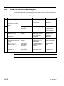
USB-ITPAK Error Messages ....................................................................................................... 8-14
8.4.1
Error messages common to all dialog boxes ................................................................... 8-14
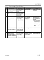
8.4.2
Error message of main dialog box ..................................................................................... 8-15
8.4.3
Error messages of [Device information setting] dialog box ........................................... 8-16
8.4.4
Error messages of [Add/change procedure] dialog box ................................................. 8-17
8.4.5
Error messages of [Data entry device settings] dialog box ............................................ 8-19
8.4.6
Error messages of [Character string data settings] dialog box ...................................... 8-19
8.4.7
Error messages of data collection dialog box .................................................................. 8-20
SERVICE NETWORK
xii
No. 99MAM024A
1
1.1
1
BASIC KNOWLEDGE
Overview
USB-ITPAK is software for inputting measurement data of measuring tools connected to
the USB Input Tool Direct (hereafter referred to as USB-ITN) (separately sold), U-WAVE
(separately sold) and USB Input Tool (hereafter referred to IT-016U) (separately sold) to
Microsoft Excel (hereafter referred to as Excel).
Users can create their own software that captures measurement data via virtual RS-232C
interface using a dedicated VCP driver supplied with USB-ITPAK.
TIP For the specifications of the virtual RS-232C interface of USB-ITN / IT-016U, refer to
"CHAPTER 7 COMMUNICATION COMMAND SPECIFICATIONS".
For details about the U-WAVE, refer to the instruction manuals supplied with U-WAVE.
USB-ITPAK supports the following functions to input data to Excel.
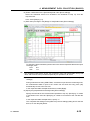
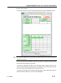
1) Inputting measurement data directly to inspection table sheets on Excel
Input cells can be specified for respective measuring tools when multiple measuring
tools are connected using USB-ITN, U-WAVE, and/or IT-016U, such as "1st measuring
tool data input to cells of column A, 2nd measuring tool data input to cells of column B".
Further, when measuring three dimensions using one measuring tool, the location of
the input cells for the dimension can be specified, such as "length data input to cell A,
width data to cell B, height data to cell C".
By specifying the location of the input cells according to the measurement procedure
of the user, inspection certificates can easily be created with Excel, and inspection
data for manufacturing processes can easily be managed.
2) Inputting multi-point measurement data using measurement jigs at a time
USB-ITPAK allows the user to issue a request from a PC for the output of
measurement data from a measuring tool connected to USB-ITN, U-WAVE and/or
IT-016U.
No. 99MAM024A
1-1
Optional USB Foot Switch Adapter (hereafter referred to as USB-FSW) and foot switch
allows acquiring measurement data of a measuring tool in batch by simply pressing a
foot switch.
NOTE When using U-WAVE, the event driven mode (special order) must be set. For details,
refer to the U-WAVEPAK User’s Manual (for the event driven).
3) Randomly inputting measurement data from multiple measuring tools to worksheets
USB-ITPAK allows you to individually set the worksheets and cells to which
measurement data is to be input for each measuring tool. This allows multiple
operators to randomly perform measurements and input the measurement data from
each measuring tool to the respectively specified cells.
4) Request for data output to measuring tool using foot switch
With the USB-FSW and a foot switch, USB-ITPAK allows you to instruct a measuring
tool to output measurement data without having to operate the PC, by using the foot
switch.
Measurement data output can also be requested from the PC if there is no foot switch.
Connecting a foot switch (option) to IT-016U enables data request using the foot
switch.
NOTE When using U-WAVE, the event driven mode (special order) must be set. For details,
refer to the U-WAVEPAK User’s Manual (for the event driven).
5) Data cancellation using foot switch
With the USB-FSW and a foot switch, USB-ITPAK allows you to cancel measurement
data without having to operate the PC, by using the foot switch, in order to restore the
state before measurement.
Measurement data can also be canceled via the PC if there is no foot switch.
6) Inputting character string such as "PASS" or "FAIL" using foot switch
When preparing inspection certificates, there are items such as visual inspection
results that need character input. However, inputting character strings such as "PASS"
and "FAIL" from the keyboard at each inspection takes time and effort. Also, it may not
be possible to operate the keyboard in some work environments.
With USB-ITPAK, character strings such as "PASS" and "FAIL" can be registered in
advance and input to the specified cells by simply pressing a foot switch, when the
USB-FSW and a foot switch are used.
1-2
No. 99MAM024A
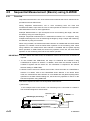
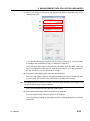
1. BASIC KNOWLEDGE
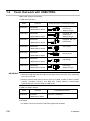
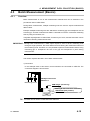
1.2
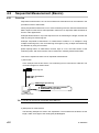
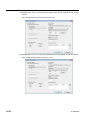
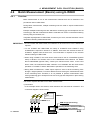
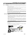
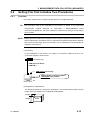
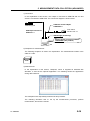
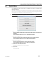
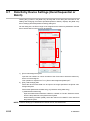
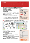
System Configuration
An example of the system configuration of USB Input Tool Direct is shown in the figure
below.
Foot Switch
No.937179T / 12AAJ088
Measuring tool
USB Input Tool Direct "USB-ITN"
Nos.06ADV380A to 06ADV380G
/ 06AEJ480A to 06AEJ480G
for Korea
Software for setup and data collection
USB-ITPAK (This product)
No.06AEN846
PC
Digimatic Connecting Cable
USB Input Tool "IT-016U"
No.264-016 / 264-016K for Korea
Measuring tool
Foot Switch
No. 937179T / 12AAJ088
USB Foot Switch Adapter "USB-FSW"
No.06ADV384 / 06AEJ484 for Korea
U-WAVE
USB dongle
(accessory)
Measuring tool
Provide the measuring tool(s) and PC according to the system to be used.
If any of multiple USB-ITN, USB-FSW, U-WAVE, or IT-016U units (more than 1 model is
allowed) are used, a corresponding number of USB ports are required. If the PC does
not have the required number of USB ports, use a USB hub (commercially available).
Select USB-ITN or U-WAVE that is suitable for the connector of the measuring tool to
be used.
Supported connectors can be identified by suffixes A to G. Choose an appropriate
device.
For details about the USB-ITN, refer to any of "1.4 Tools that work with USB-ITPAK", the
user’s manual of the USB-ITN, or each instruction manual supplied with U-WAVE.
Provide USB-FSW and foot switch units only if required.
IT-016U requires a Digimatic connecting cable to be connected with the measuring tool.
The data request sent from the foot switch connected to IT-016U also functions in the
HID mode, however it will only be input to the connection source IT-016U.
IMPORTANT When processing data collection with USB-ITPAK, it requires the autosave function of
Excel to be disabled.
(For operations regarding Excel, refer to instructions of Excel.)
No. 99MAM024A
1-3
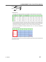
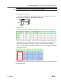
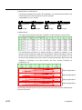
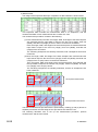
USB-ITPAK operates only when the supplied USB dongle is connected to the PC.
Connect the USB dongle to the PC before using USB-ITPAK. In addition, USB-ITPAK
operates only when the version of USB dongle is the same or higher than that of
USB-ITPAK. When using a USB dongle not supplied, check the version.
Serial label
USB dongle(Serial side)
###:Version display
Example: 010 ~ 999
USB dongles that can be used with USB-ITPAK
Version of USB-ITPAK
Version of USB dongle
V1.0(010) V2.0(020) V99.9(999)
V1.0xx
✓
✓
✓
V2.0xx
-
✓
✓
V99.9xx
-
-
✓
1-4
No. 99MAM024A
1. BASIC KNOWLEDGE
1.3
PC Specification Requirements
The following specifications are required of the PC on which USB-ITPAK is used.
<Hardware Specifications>
Monitor (800 x 600 or higher resolution, 256 or more colors)
10 MB or more hard disk space
(5 MB is the minimum required amount for installation.)
CD-ROM drive
(required to install USB-ITPAK)
2 or more USB ports
(required to connect any of the USB dongle, or USB-ITN / USB-FSW / U-WAVE-R / IT-016U)
NOTE Other hardware specifications must meet those required by the OS on which
USB-ITPAK runs.
<Software Specifications>
OS:
Microsoft Windows 2000
Professional
SP4
Microsoft Windows XP
Professional
SP2 or higher
Microsoft Windows XP
Home Edition
SP2 or higher
Microsoft Windows Vista
Ultimate
Microsoft Windows Vista
Enterprise
Microsoft Windows Vista
Business
Microsoft Windows Vista
Home Premium
Microsoft Windows Vista
Home Basic
Microsoft Windows 7
Ultimate
Microsoft Windows 7
Enterprise
Microsoft Windows 7
Professional
Microsoft Windows 7
Home Premium
Microsoft Windows 7
Home Basic
Microsoft Windows 7
Starter
Microsoft Windows 8 / 8.1
Microsoft Windows 8 / 8.1
Pro
Microsoft Windows 8 / 8.1
Enterprise
(Update included in Windows 8.1)
IMPORTANT Use the same OS language as the USB-ITPAK language. The operation on an OS with
a different language is not guaranteed.
To input measurement data to Excel using USB-ITPAK, Excel 2000 or higher is
required.
No. 99MAM024A
1-5
1.4
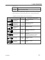
Tools that work with USB-ITPAK
USB-ITPAK supports the following.
1) USB Input Tool Direct
Model
USB-ITN-A
Code No.
Connector type on measuring tool side
Equipped with the
DATA switch
Waterproof type
06ADV380A
/ 06AEJ480A for Korea
USB-ITN-B
Equipped with the
DATA switch
Waterproof type
06ADV380B
/ 06AEJ480B for Korea
USB-ITN-C
06ADV380C
Equipped with the
DATA switch
/ 06AEJ480C for Korea
USB-ITN-D
06ADV380D
Flat (10-pin)
/ 06AEJ480D for Korea
USB-ITN-E
06ADV380E
Round (6-pin)
/ 06AEJ480E for Korea
USB-ITN-F
06ADV380F
Flat straight
/ 06AEJ480F for Korea
USB-ITN-G
06ADV380G
Flat straight
Waterproof type
/ 06AEJ480G for Korea
IMPORTANT Select the USB-ITN model according to the shape of the connector of the measuring
tool to be connected.
Mitutoyo products other than the above (such as IT-005D, IT-006N, IT-007R, IT-008Z,
IT-012U, IT-013UD, IT-014UT, and MUX-10F) employ different communication
methods and thus cannot be used for USB-ITPAK.
2) USB Foot Switch Adapter
Model
USB-FSW
Code No.
06ADV384
/ 06AEJ484 for Korea
Compatible foot switch
937179T / 12AAJ088
3) U-WAVE
For details, refer to the instruction manuals supplied with U-WAVE.
1-6
No. 99MAM024A
1. BASIC KNOWLEDGE
4) USB Input Tool
Model
IT-016U
Code No.
264-016 / 264-016K for Korea
A Digimatic connecting cable (option) is required to connect with the measuring tool.
Select the digimatic connecting cable suitable for the connected measuring tool.
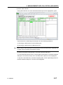
<Digimatic connecting cables for each connected device>
The connector style of measuring tool
Part Nos.
Equipped with the
output switch
Waterproof type
1m: 05CZA624
Equipped with the
output switch
Waterproof type
1m: 05CZA662
Equipped with the
output switch
Straight
1m: 959149
2m: 05CZA625
2m: 05CZA663
2m: 965014
1m: 937387
Round (6-pin)
2m: 965013
1m: 905338
Flat straight
Flat straight
Waterproof type
No. 99MAM024A
ABS coolant proof caliper
IP65/66/67
Coolant proof micrometer
Quantumike IP65
ABS digimatic caliper
2m: 959150
1m: 936937
Flat (10-pin)
Main Applicable measuring tool
2m: 905409
1m: 21EAA194
2m: 21EAA190
ABS digimatic indicator ID-H/F
QM-Height
Quick micro
Digimatic Holtest (Models before 2007)
ABS Borematic (Models before 2011)
ABS digimatic indicator
ID-C/S/U
ABS digimatic indicator
ID-N/B
1-7
1.5
Technical Terms
1.5.1
Device No.
The device No. displayed on each the USB connector ("A" plug) of the USB-ITN unit,
USB-FSW unit, USB dongle, U-WAVE, and IT-016U unit is individual identification
information. These devices Nos. are fixed and cannot be changed.
USB-ITPAK displays the device No. of the USB-ITN, USB-FSW, U-WAVE, and IT-016U
units as the default.
The device Nos. displayed by USB-ITPAK can be changed.
NOTE The "Device ID" of U-WAVE means the "Device No." of USB-ITPAK.
TIP For how to change device Nos., refer to "CHAPTER 4 MEASUREMENT DATA
COLLECTION (BASICS)".
1.5.2
Dedicated VCP driver
USB-ITN / IT-016U operates in either the Human Interface Device (HID) or Virtual COM
Port (VCP) mode.
USB-ITPAK uses USB-ITN / IT-016U in the VCP mode to achieve various functions.
The dedicated VCP driver is required to use USB-ITN / IT-016U in the VCP mode, and is
included on the CD supplied with USB-ITPAK.
TIP For how to install the dedicated VCP driver, refer to "2.2 Installing and Uninstalling the
VCP driver".
1.5.3
Procedure
The procedure consists of information that specifies the data collection method in
USB-ITPAK. This information includes the Excel file that is the output destination, the
USB-ITN / U-WAVE / IT-016U unit to be used, the input method ("sequential", "batch", etc.),
the cell movement direction following input ("down", "right", etc.).
The procedure is saved as a "setting file" by USB-ITPAK.
Inspections can be performed efficiently by preparing in-process inspection and
acceptance inspection procedures in advance.
1.5.4
Setting files
These are the files for saving the "procedures" used in USB-ITPAK (file extension: itp ,it2).
1-8
No. 99MAM024A
1. BASIC KNOWLEDGE
1.5.5
Sequential measurement
Sequential measurement is a measurement method that can be selected in the
"procedure" used by USB-ITPAK.
During sequential measurement, one or more measuring tools are used and the
measurement data is input from the measuring tool(s) registered beforehand in the
procedure to an Excel inspection table sheet.
Example: Measurements in a pre-set sequence using one measuring tool, such as
measuring the length and then the width
Example: Measurements using multiple measuring tools, such as measuring the length
with a caliper and then the diameter using a micrometer
1.5.6
Batch measurement
Batch measurement is a measurement method that can be selected in the "procedure"
used by USB-ITPAK.
During batch measurement, measurement data is acquired in batch from multiple
measuring tools.
Example: Batch collection of measurement data from all measuring tools registered in the
procedure by attaching multiple measuring tools to measurement jigs, setting workpieces
to these tools, and operating a foot switch
1.5.7
Individual measurement
Individual measurement is a measurement method that can be selected in the "procedure"
used in USB-ITPAK.
For individual measurement, the worksheet and cells to which the measurement data is
input are set for each measuring tool. This method allows multiple operators to randomly
perform measurement, and the measurement data from each measuring tool is input to
the respectively specified cells.
Example: Data collection from three measuring tools operated by respective operators
1.5.8
Data entry application
When selecting [Excel], data input is available only in Excel (2000 or higher).
Data input is not available using spreadsheet software other than Excel (such as
OpenOffice Calc).
When selecting [Optional], data input is available in an active application (that means
keyboard input is available) at the time of data collection.
Data input is also available using spreadsheet software equivalent to Excel (such as
OpenOffice Calc).
No. 99MAM024A
1-9
MEMO
1-10
No. 99MAM024A
2
2
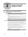
INSTALLATION AND
UNINSTALLATION
2.1
Installing and Uninstalling USB-ITPAK
2.1.1
Installing USB-ITPAK
NOTE To install USB-ITPAK, log in to Windows with "Administrator" authority.
Do not connect USB-ITN, USB-FSW or IT-016U to the PC before USB-ITPAK has been
installed.
To use USB-ITN, USB-FSW or IT-016U with USB-ITPAK, a dedicated VCP driver must
be installed for each USB-ITN, USB-FSW or IT-016U unit.
For how to install the dedicated VCP driver, refer to "2.2 Installing and Uninstalling the
VCP driver".
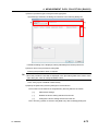
IMPORTANT When using USB-ITPAK on Windows 8/8.1, ".NET Framework 3.5" is required.
If ".NET Framework 3.5" has not been installed on Windows 8/8.1, connect the PC to
the Internet before installing USB-ITPAK. While installing USB-ITPAK, ".NET
Framework 3.5", which is required for operation, will be downloaded from the Internet.
After USB-ITPAK has been installed on Windows 8/8.1, connection of the PC to the
Internet is not required. The Internet connection is neither required when ".NET
Framework 3.5" has already been installed on Windows 8/8.1.
When using U-WAVE, U-WAVEPAK supplied with U-WAVE-R is required.
For details about the U-WAVE, refer to the instruction manuals supplied with U-WAVE.
To use U-WAVE with USB-ITPAK, perform the following in advance.
1) Install the exclusive VCP driver for each U-WAVE-R from the supplied CD with
U-WAVEPAK.
2) Register U-WAVE-T to U-WAVE-R using U-WAVEPAK.
1) Start the PC and insert the supplied CD in the CD drive.
No. 99MAM024A
2-1
2) From Windows Explorer, execute "Setup.exe" in the "Setup" folder of the supplied
CD.
If the [User Account Control] warning is displayed in Windows Vista / Windows 7/
Windows 8/8.1, perform as follows.
Windows Vista: Select [Allow].
Windows 7/ Windows 8/8.1: Click the [Yes] button.
2-2
No. 99MAM024A
2. INSTALLATION AND UNINSTALLATION
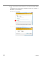
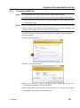
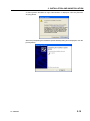
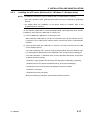
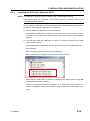
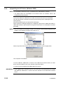
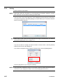
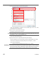
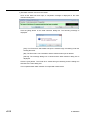
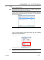
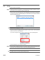
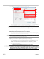
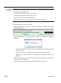
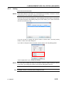
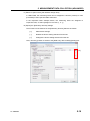
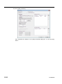
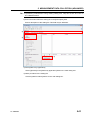
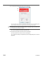
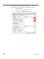
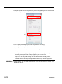
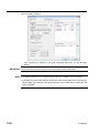
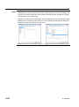
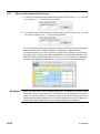
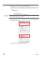
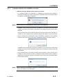
3) When the [Welcome to the USB-ITPAK Setup Wizard] dialog box is displayed, click
the [Next] button.
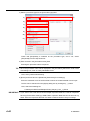
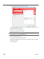
4) Read the [License Agreement] and if you accept this agreement, select [I accept the
agreement] and then click the [Next] button.
5) When the [Select Destination Location] dialog box is displayed, click the [Next]
button.
No. 99MAM024A
2-3
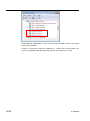
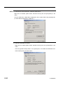
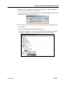
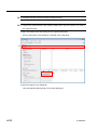
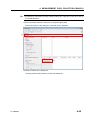
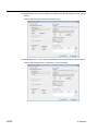
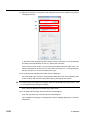
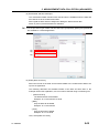
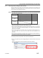
6) When the [Select Additional Tasks] dialog box is displayed, click the [Next] button. To
create an icon on the desktop, follow steps a) and b), in this sequence.
b)
a)
Click the [Next] button.
Select [Create a desktop icon].
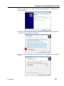
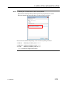
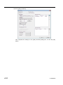
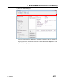
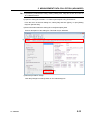
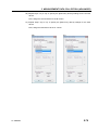
7) When the [Ready to Install] dialog box is displayed, click the [Install] button.
NOTE When USB-ITPAK has been installed, a "Sample Inspection Table File" is installed in the
"Sample" folder in the install destination folder.
If a "Sample Inspection Table File" already exists in the "Sample" folder, back up this file
to a different folder if it will be needed later before installing USB-ITPAK.
2-4
No. 99MAM024A
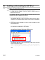
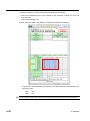
2. INSTALLATION AND UNINSTALLATION
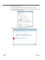
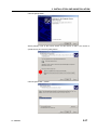
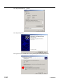
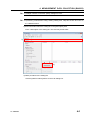
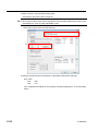
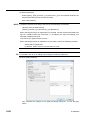
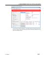
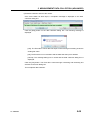
8) If Windows Installer 3.1 is not yet installed, the [Windows Installer 3.1 (KB893803)]
dialog box is displayed. Click the [Next] button.
NOTE If Windows Installer 3.1 is already installed, step 8) is skipped.
This section explains using the screenshots of Windows XP.
Read the [License Agreement] and if you accept this agreement, select [I Agree] and
then click the [Next] button.
No. 99MAM024A
2-5
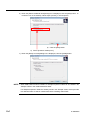
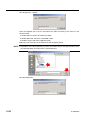
When the [Completing the Windows Installer 3.1 (KB893803) Installation Wizard]
dialog box is displayed, select [Do not restart now] and click the [Finish] button.
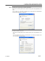
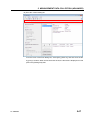
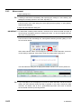
9) If Microsoft .NET Framework 2.0 is not yet installed, the [Welcome to Microsoft .NET
Framework 2.0 Setup] dialog box is displayed. Click the [Next] button.
NOTE If Microsoft .NET Framework 2.0 is already installed, step 9) is skipped.
This section explains using the screenshots of Windows XP.
2-6
No. 99MAM024A
2. INSTALLATION AND UNINSTALLATION
Read the [License Agreement] and if you accept this agreement, select [I accept the
terms of the License Agreement] and click the [Install] button.
When the [Setup Complete] dialog box is displayed, click the [Finish] button.
No. 99MAM024A
2-7
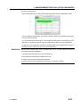
10) When the following dialog box is displayed, click the [Finish] button to complete the
installation procedure.
2-8
No. 99MAM024A
2. INSTALLATION AND UNINSTALLATION
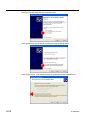
2.1.2
Uninstalling USB-ITPAK
NOTE To uninstall USB-ITPAK, log in to Windows with "Administrator" authority.
For details about the U-WAVE, refer to the instruction manuals supplied with U-WAVE.
1) Click the Start button of Windows and select [All Programs] - [USB-ITPAK], and then
[Uninstall USB-ITPAK].
NOTE If the OS is Windows 8/8.1, press the [X] key while holding down the Windows logo key.
Select [Programs and Features] from the displayed menu and open [Programs and
Features]. Select USB-ITPAK from the list and click [Uninstall].
If the [User Account Control] warning is displayed in Windows Vista / Windows 7,
perform as follows.
Windows Vista: Select [Allow].
Windows 7: Click the [Yes] button.
2) When [Are you sure you want to completely remove USB-ITPAK and all of its
components?] is displayed, click the [Yes] button.
3) When [USB-ITPAK was successfully removed from your computer.] is displayed,
uninstallation is successful. Click the [OK] button.
No. 99MAM024A
2-9
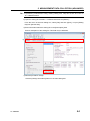
2.2
Installing and Uninstalling the VCP Driver
2.2.1
Installing the VCP driver (Windows XP)
NOTE To install the VCP driver, log in to Windows with "Administrator" authority.
For details about the installation of the device driver for U-WAVE, refer to the
U-WAVEPAK User’s Manual.
To use USB-ITN, USB-FSW or IT-016U with USB-ITPAK, a dedicated VCP driver must be
installed for each USB-ITN, USB-FSW or IT-016U unit.
1) Connect USB-ITN, USB-FSW or IT-016U to the PC.
When USB-ITN, USB-FSW or IT-016U is connected to a PC for the first time, the PC
recognizes it as a USB human interface device and the HID driver is automatically
installed.
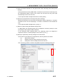
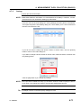
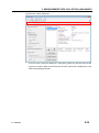
2) Check whether USB-ITN, USB-FSW or IT-016U is correctly connected as the USB
human interface device.
Click the Start button of Windows and open [Control Panel].
From [Performance and Maintenance], open [System].
Select the [Hardware] tab and open [Device Manager].
When the following is displayed, open [Human Interface Devices].
When USB-ITN, USB-FSW or IT-016U is connected to the USB connector, one [USB
Human Interface Device] is added.
Connect or disconnect USB-ITN, USB-FSW or IT-016U and check whether the
number of displayed [USB Human Interface Device] increases or decreases as a
result.
2-10
No. 99MAM024A
2. INSTALLATION AND UNINSTALLATION
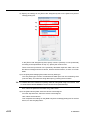
NOTE To identify the connected device, follow the steps below.
Right-click the desired [USB Human Interface Device] and click [Properties] in the
menu.
Check if USB-ITN or USB-FSW is displayed in the Location field of the [General] tab.
(IT-016U will be displayed as "USB-ITN".)
3) Install the dedicated VCP driver.
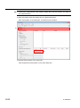
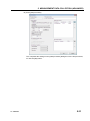
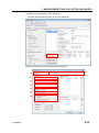
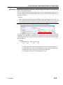
Right-click the added [USB Human Interface Device] and click [Properties] in the
menu.
Click the [Update Driver] button in the [Driver] tab, and install the dedicated VCP
driver following the procedure below.
No. 99MAM024A
2-11
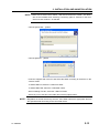
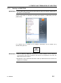
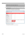
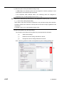
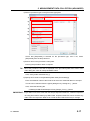
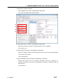
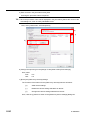
Select [No, not this time] and click the [Next] button.
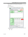
Select [Install from a list or specific location] and click the [Next] button.
Select [Don’t search. I will choose the driver to install.] and click the [Next] button.
2-12
No. 99MAM024A
2. INSTALLATION AND UNINSTALLATION
NOTE Make sure to select "Don't search. I will choose the driver to install.". The driver
will not be installed when selecting a searching place if "Search for the best
driver in these locations." is selected.
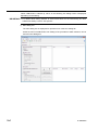
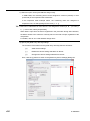
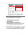
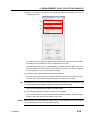
Click the [Have Disk…] button.
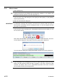
Click the [Browse…] button.
Insert the supplied CD in the PC and select the folder according to the device in the
"Drivers" folder.
To install USB-ITN, select the "USB-ITN" folder.
To install USB-FSW, select the "USB-FSW" folder.
When installing IT-016U, select the "USB-ITN" folder.
Select any one of the files in the folder and click the [Open] button.
NOTE Regardless of the file selected by the user, the installer selects the appropriate file from
the specified folder according to the connected device.
No. 99MAM024A
2-13
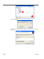
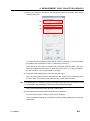
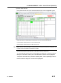
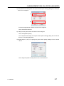
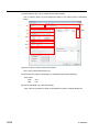
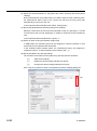
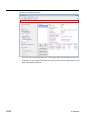
Click the [OK] button.
Check that USB-ITN or USB-FSW is selected in the Model field, and then click the
[Next] button.
2-14
No. 99MAM024A
2. INSTALLATION AND UNINSTALLATION
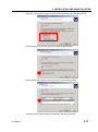
A warning about Windows XP logo authentication is displayed. Click the [Continue
Anyway] button.
When the [Completing the Hardware Update Wizard] dialog box is displayed, click the
[Finish] button.
No. 99MAM024A
2-15
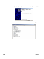
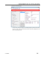
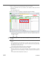
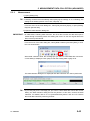
4) If the hardware has been correctly updated, the item of the device that has been
installed moves from [Human Interface Device] to USB-ITN (COMx) or USB-FSW
(COMx) under [Ports (COM & LPT)] in the [Device Manager] dialog box.
NOTE The "x" in COMx is the COM port number; the installer automatically assigns an
available number. In the following example, this number is "3".
When the VCP driver is installed, USB-ITN, USB-FSW and IT-016U are recognized as
ports (COM & LPT), not human interface devices. At this time, IT-016U will be displayed
as "USB-ITN".
5) If multiple USB-ITN, USB-FSW or IT-016U units are to be connected, repeat steps 1)
to 4).
NOTE When installing multiple USB-ITN, USB-FSW or IT-016U units, the above procedure is
required for each unit.
2-16
No. 99MAM024A
2. INSTALLATION AND UNINSTALLATION
2.2.2
Installing the VCP driver (Windows 8/8.1 / Windows 7 / Windows Vista)
NOTE To install the VCP driver, log in to Windows with "PC administrator" authority.
If the OS is Windows Vista, [USB Human Interface Device] corresponds to [USB Input
Device].
For details about the installation of the device driver for U-WAVE, refer to the
U-WAVEPAK User’s Manual.
To use USB-ITN, USB-FSW or IT-016U with USB-ITPAK, a dedicated VCP driver must be
installed for each USB-ITN, USB-FSW or IT-016U unit.
1) Connect USB-ITN, USB-FSW or IT-016U to the PC.
When USB-ITN, USB-FSW or IT-016U is connected to a PC for the first time, the PC
recognizes it as a USB human interface device and the HID driver is automatically
installed.
2) Check whether USB-ITN, USB-FSW or IT-016U is correctly connected as the USB
human interface device.
If the OS is Windows 8/8.1, press the [X] key while holding down the Windows logo
key. Select [Device Manager] from the displayed menu and open [Device Manager].
If the OS is Windows 7 / Windows Vista, click the Windows Start button and perform
as follows in [Control Panel].
Windows 7: Open [System and Security], and open [Device Manager] in [System].
Windows Vista: From [System and Maintenance], open [Device Manager].
If the [User Account Control] warning is displayed, perform as follows.
Windows 7: click [Yes].
Windows Vista: click [Continue].
When the following is displayed, open [Human Interface Devices].
No. 99MAM024A
2-17
When USB-ITN, USB-FSW or IT-016U is connected to the USB connector, one [USB
Input Device] is added.
Connect or disconnect USB-ITN, USB-FSW or IT-016U and check whether the
number of displayed [USB Input Device] increases or decreases as a result.
2-18
No. 99MAM024A
2. INSTALLATION AND UNINSTALLATION
NOTE To identify the connected device, follow the steps below.
Right-click the desired [USB Input Device] and click [Properties] in the menu.
Select the [Details] tab and select [Device Instance Path] in Property.
Devices can be identified depending on the contents of [Value] as follows.
USB-ITN :USB\VID_0FE7&PID_4001\ ********
USB-FSW:USB\VID_0FE7&PID_4002\ ********
IT-016U
:USB\VID_0FE7&PID_4001\ 8*******
******** indicates an 8-digit serial number.
No. 99MAM024A
2-19
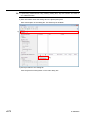
3) Install the dedicated VCP driver.
Right-click the added [USB Input Device] and click [Properties] in the menu.
Click the [Update Driver] button in the [Driver] tab, and install the dedicated VCP
driver following the procedure below.
Select [Browse my computer for driver software].
2-20
No. 99MAM024A
2. INSTALLATION AND UNINSTALLATION
Select [Let me pick from a list of device drivers on my computer].
Click the [Have Disk…] button.
No. 99MAM024A
2-21
Click the [Browse…] button.
Insert the supplied CD in the PC and select the folder according to the device in the
"Drivers" folder.
To install USB-ITN, select the "USB-ITN" folder.
To install USB-FSW, select the "USB-FSW" folder.
To install IT-016U, select the "USB-ITN" folder.
Select any one of the files in the folder and click the [Open] button.
NOTE Regardless of the file selected by the user, the installer selects the appropriate file from
the specified folder according to the connected device.
Click the [OK] button.
2-22
No. 99MAM024A
2. INSTALLATION AND UNINSTALLATION
Check that USB-ITN or USB-FSW is selected in the Model field, and then click the [Next]
button.
Click the [Install] button.
No. 99MAM024A
2-23
When the message [Windows has successfully updated your driver software] is displayed,
the installation is completed. Click the [Close] button.
4) If the hardware has been correctly updated, the item of the device that has been
installed moves from [Human Interface Device] to USB-ITN (COMx) or USB-FSW
(COMx) under [Ports (COM & LPT)] in the [Device Manager] dialog box.
NOTE The "x" in COMx is the COM port number; the installer automatically assigns an
available number. In the following example, this number is "4".
When the VCP driver is installed, USB-ITN, USB-FSW and IT-016U are recognized as
ports (COM & LPT), not human interface devices. At this time, IT-016U will be displayed
as "USB-ITN".
5) If multiple USB-ITN, USB-FSW or IT-016U units are to be connected, repeat steps 1)
to 4).
NOTE When installing multiple USB-ITN, USB-FSW or IT-016U units, the above procedure is
required for each unit.
2-24
No. 99MAM024A
2. INSTALLATION AND UNINSTALLATION
2.2.3
Installing the VCP driver (Windows 2000)
NOTE To install the VCP driver, log in to Windows with "Administrator" authority.
For details about the installation of the device driver for U-WAVE, refer to the
U-WAVEPAK User’s Manual.
To use USB-ITN, USB-FSW or IT-016U with USB-ITPAK, a dedicated VCP driver must be
installed for each USB-ITN, USB-FSW or IT-016U unit.
1) Connect USB-ITN, USB-FSW or IT-016U to the PC.
When USB-ITN, USB-FSW or IT-016U is connected to a PC for the first time, the PC
recognizes it as a USB human interface device and the HID driver is automatically
installed.
2) Check whether USB-ITN, USB-FSW or IT-016U is correctly connected as the USB
human interface device.
Click the Start button of Windows and open [Control Panel] from the [Settings] menu.
Open [System].
Select the [Hardware] tab and open [Device Manager].
When the following is displayed, open [Human Interface Devices].
When USB-ITN, USB-FSW or IT-016U is connected to the USB connector, one [USB
Human Interface Device] is added.
Connect or disconnect USB-ITN, USB-FSW or IT-016U and check whether the
number of displayed [USB Human Interface Device] increases or decreases as a
result.
No. 99MAM024A
2-25
NOTE To identify the connected device, follow the steps below.
Right-click the desired [USB Human Interface Device] and click [Properties] in the
menu.
Check if USB-ITN or USB-FSW is displayed in the Location field of the [General] tab.
(IT-016U will be displayed as "USB-ITN".)
3) Install the dedicated VCP driver.
Right-click the added [USB Human Interface Device] and click [Properties] in the
menu.
Click the [Update Driver] button in the [Driver] tab, and install the dedicated VCP
driver following the procedure below.
2-26
No. 99MAM024A
2. INSTALLATION AND UNINSTALLATION
Click the [Next] button.
Select [Display a list of the known drivers for this device so that I can choose a
specific driver] and click the [Next] button.
Click the [Have Disk...] button.
No. 99MAM024A
2-27
Click the [Browse…] button.
Insert the supplied CD in the PC and select the folder according to the device in the
"Drivers" folder.
To install USB-ITN, select the "USB-ITN" folder.
To install USB-FSW, select the "USB-FSW" folder.
To install IT-016U, select the "USB-ITN" folder.
Select any one of the files in the folder and click the [Open] button.
NOTE Regardless of the file selected by the user, the installer selects the appropriate file from
the specified folder according to the connected device.
Click the [OK] button.
2-28
No. 99MAM024A
2. INSTALLATION AND UNINSTALLATION
NOTE When the [OK] button on the above dialog box is clicked, the "The specified location
does not contain information about your hardware." message may be displayed and the
VCP driver may not be recognized. In this case, select again the folder according to the
model in the "Drivers" folder on the supplied CD. For details, refer to "8.3.1 Problems
related to installing VCP driver".
Check that USB-ITN or USB-FSW is selected in the Model field, and then click the [Next]
button.
When the [Start Device Driver Installation] dialog box is displayed, click the [Next] button.
When the [Completing the Upgrade Device Driver Wizard] dialog box is displayed, click
the [Finish] button.
No. 99MAM024A
2-29
4) If the hardware has been correctly updated, the item of the device that has been
installed moves from [Human Interface Device] to USB-ITN (COMx) or USB-FSW
(COMx) under [Ports (COM & LPT)] in the [Device Manager] dialog box.
NOTE The "x" in COMx is the COM port number; the installer automatically assigns an
available number. In the following example, this number is "4".
When the VCP driver is installed, USB-ITN, USB-FSW and IT-016U are recognized as
ports (COM & LPT), not human interface devices. At this time, IT-016U will be displayed
as "USB-ITN".
5) If multiple USB-ITN, USB-FSW or IT-016U units are to be connected, repeat steps 1)
to 4).
NOTE When installing multiple USB-ITN, USB-FSW or IT-016U units, the above procedure is
required for each unit.
2-30
No. 99MAM024A
2. INSTALLATION AND UNINSTALLATION
2.2.4
Uninstalling the VCP driver (Windows XP)
NOTE To uninstall the VCP driver, log in to Windows with "Administrator" authority.
For details about the uninstallation of the device driver for U-WAVE, refer to the
U-WAVEPAK User’s Manual.
Connect the USB-ITN, USB-FSW or IT-016U unit whose VCP driver is to be removed.
Click the Start button of Windows and open [Control Panel].
Open [System] from [Performance and Maintenance].
Select the [Hardware] tab and open [Device Manager].
When the [Device Manager] dialog box is displayed, right-click the USB-ITN (COMx) or
USB-FSW (COMx) in [Ports (COM & LPT)] whose VCP driver is to be deleted, and select
[Uninstall].
NOTE The "x" in COMx is the COM port number. This number is automatically assigned by the
installer. In the following example, this number is "4".
When the [Confirm Device Removal] dialog box is displayed, click the [OK] button.
This completes uninstallation.
If the OS is restarted or USB-ITN, USB-FSW or IT-016U is disconnected and then
reconnected, the PC recognizes USB-ITN, USB-FSW or IT-016U as a USB human
interface device similarly to when it is connected to the PC for the first time and the HID
driver is automatically installed.
No. 99MAM024A
2-31
2.2.5
Uninstalling the VCP driver (Windows 8/8.1 / Windows 7 / Windows Vista)
NOTE To uninstall the VCP driver, log in to Windows with "PC administrator" authority.
For details about the uninstallation of the device driver for U-WAVE, refer to the
U-WAVEPAK User’s Manual.
Connect the USB-ITN, USB-FSW or IT-016U unit whose VCP driver is to be removed.
If the OS is Windows 8/8.1, press the [X] key while holding down the Windows logo key.
Select [Device Manager] from the displayed menu and open [Device Manager].
If the OS is Windows 7 / Windows Vista, click the Windows Start button and perform as
follows in [Control Panel].
Windows 7: Open [System and Security], and open [Device Manager] in [System].
Windows Vista: From [System and Maintenance], open [Device Manager].
If the [User Account Control] warning is displayed, perform as follows.
Windows 7: click [Yes].
Windows Vista: click [Continue].
When the [Device Manager] dialog box is displayed, right-click the USB-ITN (COMx) or
USB-FSW (COMx) in [Ports (COM & LPT)] whose VCP driver is to be deleted, and select
[Uninstall].
NOTE The "x" in COMx is the COM port number. This number is automatically assigned by the
installer. In the following example, this number is "4".
When the [Confirm Device Uninstall] dialog box is displayed, select the [Delete the driver
software for this device.] and click the [OK] button.
✓
This completes uninstallation.
If the OS is restarted or USB-ITN, USB-FSW or IT-016U is disconnected and then
2-32
No. 99MAM024A
2. INSTALLATION AND UNINSTALLATION
reconnected, the PC recognizes USB-ITN, USB-FSW or IT-016U as a USB human
interface device similarly to when it is connected to the PC for the first time and the HID
driver is automatically installed.
No. 99MAM024A
2-33
2.2.6
Uninstalling the VCP driver (Windows 2000)
NOTE To uninstall the VCP driver, log in to Windows with "Administrator" authority.
For details about the uninstallation of the device driver for U-WAVE, refer to the
U-WAVEPAK User’s Manual.
Connect the USB-ITN, USB-FSW or IT-016U unit whose VCP driver is to be deleted.
Click the Start button of Windows and open [Control Panel] from the [Settings] menu.
Open [System].
Select the [Hardware] tab and open [Device Manager].
When the [Device Manager] dialog box is displayed, right-click the USB-ITN (COMx) or
USB-FSW (COMx) in [Ports (COM & LPT)] whose VCP driver is to be deleted, and select
[Uninstall].
NOTE The "x" in COMx is the COM port number. This number is automatically assigned by the
installer. In the following example, this number is "4".
When the [Confirm Device Removal] dialog box is displayed, click the [OK] button.
This completes uninstallation.
To return USB-ITN, USB-FSW or IT-016U to the USB human interface device, the HID
driver must be installed. In this case, follow the procedure below.
1) Remove the CD supplied with USB-ITPAK from the PC.
IMPORTANT If the supplied CD is inserted in the PC, the VCP driver will automatically be installed
and USB-ITN, USB-FSW or IT-016U cannot be returned to the USB human interface
device.
2-34
No. 99MAM024A
2. INSTALLATION AND UNINSTALLATION
2) Restart the OS or disconnect and connect back again the USB-ITN, USB-FSW or
IT-016U unit whose HID driver is to be installed.
When the [New Hardware Detected] dialog box is displayed followed by the [Insert
Disk] dialog box, click the [Cancel] button.
3) Click the Start button of Windows and open [Control Panel] from the [Settings] menu.
Open [System].
Select the [Hardware] tab and open [Device Manager].
The USB-ITN, USB-FSW or IT-016U is recognized as [Port (COM & LPT)]. Right-click
the USB-ITN, USB-FSW or IT-016U with the [!] mark, and select [Properties].
No. 99MAM024A
2-35
Click the [Reinstall Driver…] button.
Click the [Next] button.
Select [Search for a suitable driver for my device] and click the [Next] button.
2-36
No. 99MAM024A
2. INSTALLATION AND UNINSTALLATION
Clear all the check box for [Option search locations] and then click the [Next] button.
Select [Install one of the other drivers] and click the [Next] button.
Select [USB Human Interface Device] and then click the [Next] button.
If a warning about digital signature is displayed, click the [Yes] button.
No. 99MAM024A
2-37
When the [Completing the Upgrade Device Driver Wizard] dialog box is displayed,
click the [Finish] button.
This completes the HID driver installation procedure. From Device Manager, check
that USB-ITN, USB-FSW or IT-016U is connected as a USB human interface device.
2-38
No. 99MAM024A
3
3
STARTUP AND
TERMINATION OF
USB-ITPAK
3.1
Starting up USB-ITPAK
3.1.1
Connecting the measuring tool and foot switch to the PC
1) Connect the measuring tool to USB-ITN and connect USB-ITN to a USB port of the
PC.
2) Connect the foot switch to USB-FSW and connect USB-FSW to a USB port of the PC.
3) Connect the measuring tools to U-WAVE-T and connect U-WAVE-R to the USB port of
the PC.
4) Connect the measuring tool to IT-016U using a Digimatic connecting cable, and
connect IT-016U to a USB port of the PC.
IMPORTANT Select the USB-ITN and U-WAVE-T appropriate for the measuring tool to be used.
For details, refer to "1.4 Tools that work with USB-ITPAK".
For details about the U-WAVE, refer to the instruction manuals supplied with U-WAVE.
If any of multiple USB-ITN, USB-FSW, U-WAVE-R or IT-016U units (more than 1 model
is possible) are used, a corresponding number of USB ports are required. If the PC
does not have the required number of USB ports, use a USB hub (commercially
available).
To use USB-ITN, USB-FSW or IT-016U with USB-ITPAK, a dedicated VCP driver must
be installed for each USB-ITN or USB-FSW unit.
For how to install the dedicated VCP driver, refer to "2.2 Installing and Uninstalling the
VCP driver".
To use U-WAVE with USB-ITPAK, the installation of device driver for each U-WAVE-R is
required.
When using U-WAVE, U-WAVEPAK supplied with U-WAVE-R is required.
For details about the U-WAVE, refer to the instruction manuals supplied with U-WAVE.
To use U-WAVE with USB-ITPAK, perform the following in advance.
1) Install the exclusive VCP driver for each U-WAVE-R from the supplied CD with
No. 99MAM024A
3-1
U-WAVEPAK.
2) Register U-WAVE-T to U-WAVE-R using U-WAVEPAK.
Do not use USB-ITPAK and U-WAVEPAK at the same time.
Be sure to exit U-WAVEPAK before starting up USB-ITPAK.
Be sure to exit USB-ITPAK before starting up U-WAVEPAK.
The VCP communication may fail when both of them are used at the same time.
TIP USB-ITPAK and U-WAVEPAK are not required to be installed on the same PC. Even if
U-WAVE-T has been registered to U-WAVE-R using U-WAVEPAK on a different PC, the
registered settings will be valid on the PC on which USB-ITPAK has been installed.
3.1.2
Connecting the USB dongle to the PC
Connect the supplied USB dongle to a USB port on the PC to be used.
IMPORTANT USB-ITPAK can be installed even if the USB dongle is not inserted, but the USB dongle
is required to start up USB-ITPAK.
3-2
No. 99MAM024A
3. STARTUP AND TERMINATION OF USB-ITPAK
3.1.3
Starting up USB-ITPAK
IMPORTANT To use USB-ITPAK, Microsoft Excel (Excel 2000 or higher) is required. Install Excel on
the same PC as USB-ITPAK.
Click the Start button of Windows and select [All Programs] - [USB-ITPAK], and then
[USB-ITPAK].
If a shortcut icon is created on the desktop, USB-ITPAK can be started up by
double-clicking this icon.
IMPORTANT If any of USB-ITN, USB-FSW, U-WAVE-R or IT-016U (multiple choices allowed) is
connected after USB-ITPAK is started up, the device is not recognized. In this case, exit
USB-ITPAK and then restart it.
Windows 8/8.1 has no Windows Start button. Start up USB-ITPAK from the shortcut icon
created on the desktop.
No. 99MAM024A
3-3
When USB-ITPAK is started up, either of the following two dialog boxes is displayed,
depending on the setting.
IMPORTANT For details about setting whether to select Quick Menu as the initial dialog box after
USB-ITPAK startup, refer to "6.5 Options".
1) Main dialog box
The main dialog box is displayed for operators who create the setting file.
All the functions of USB-ITPAK, from setting of the procedure to data collection, can be
used from this dialog box.
3-4
No. 99MAM024A
3. STARTUP AND TERMINATION OF USB-ITPAK
2) Quick Menu
Quick Menu is displayed for operators who collect data.
Operators can start measurement by clicking the [Data collection] button to open an
already set procedure (setting file). Quick Menu is very useful for performing actual
measurement work.
3.1.4
Exiting USB-ITPAK
IMPORTANT Save data if it is not saved, before exiting USB-ITPAK.
Perform one of the two following ways to exit USB-ITPAK.
1: Click [Exit] button in Quick Menu.
2: Select [File] and then [Exit] on the main dialog box.
3.1.5
Disconnecting the USB dongle from the PC
Exit USB-ITPAK before disconnecting the USB dongle from the PC.
NOTE To continuously use USB-ITPAK, keep the USB dongle connected.
3.1.6
Disconnecting the measuring tool and foot switch from the PC
Exit USB-ITPAK before disconnecting any of USB-ITN, USB-FSW, U-WAVE-R or IT-016U
from the USB ports of the PC.
NOTE To continuously use USB-ITPAK, keep USB-ITN, USB-FSW, U-WAVE-R or IT-016U
connected.
No. 99MAM024A
3-5
MEMO
3-6
No. 99MAM024A
4
4
MEASUREMENT DATA
COLLECTION (BASICS)
This chapter explains the basic use of USB-ITPAK.
"CHAPTER 5 MEASUREMENT DATA COLLECTION (ADVANCED)" explains the
advanced use of USB-ITPAK, such as collecting data by using the foot switch and
combining multiple procedures.
"CHAPTER 6 DIALOG BOX CONFIGURATIONS OF USB-ITPAK" describes the menus
and dialog box configuration for all the functions of USB-ITPAK.
4.1
General Cautions Regarding Use
Carefully read the following cautions before using USB-ITPAK.
1. Handling Excel files registered in USB-ITPAK procedures
USB-ITPAK manages Excel files by using the Excel workbook and worksheet names
registered to procedures.
Therefore, do not make the following changes to Excel files registered to procedures in
Excel:
・Deleting or changing workbook and worksheet names
・Saving a workbook in a different folder
2. Handling Excel files currently used for data collection
Do not perform the following manipulations in Excel while collecting data by executing a
procedure in USB-ITPAK:
・Exiting Excel
・Closing an Excel file registered to a procedure
・Changing the contents of an Excel file registered to a procedure.
3. Executing procedure test (recommended)
Multiple procedures can be registered to the setting file of USB-ITPAK to provide a
complex procedure that can be run as a whole. Before running procedures, it is
recommended to check their operation by testing them beforehand.
No. 99MAM024A
4-1
4.2
Sequential Measurement (Basics)
4.2.1
Overview
Sequential measurement is one of the measurement methods that can be selected in the
procedures used in USB-ITPAK.
During sequential measurement, one or more measuring tools are used and measurement
data is input from the tools to cells specified in advance in an inspection table worksheet in
Excel or other applications.
Example: Measurement in a pre-set sequence such as measuring the length, and then the
width by using one measuring tool
Example: Sequential measurement of measurement locations on a workpiece using
multiple measuring tools, such as measuring the length by using a caliper and measuring
the diameter by using a micrometer
[Data request] button of USB-ITPAK, function keys of a PC, the DATA switch of the
measuring tools, and the foot switch can be used when collecting measurement data.
This section explains the basic use of sequential measurement.
1) Connection
In the example used in this section, one measuring tool is connected to USB-ITN. The
connection diagram is shown below.
Measuring tool
USB Input Tool Direct
USB-ITN x 1
USB dongle (accessory)
Setting & data collection software
USB-ITPAK (this product)
PC
TIP IT-016U can be used in combination with USB-ITN.
2) Workpiece for measurement
The following workpiece is used in the explanation. The measurement locations are the
length, width, and height of the rectangular parallelepiped.
4-2
No. 99MAM024A
4. MEASUREMENT DATA COLLECTION (BASICS)
Length
Height
Width
3) Measurement
The image of the inspection table upon completion of data collection is shown below.
In this measurement procedure, the length, width, and height of the first workpiece are
measured and the input data is output to the first row (Length), the second row (Width),
and the third row (Height), respectively, of the X1 column on the Excel worksheet.
Next, the second workpiece is similarly measured, and so on, until all five workpieces
have been measured.
Length (1)
↓
Width (1)
↓
Height (1)
Height (5)
The following describes how to set up the measurement procedure, perform measurement,
and save the results.
No. 99MAM024A
4-3
4.2.2
Setting
1) Check the device information.
NOTE USB-ITPAK loads the information of connected devices at startup. Therefore, connect
all the devices to be used before starting up USB-ITPAK.
From the menu of the main dialog box, select [Settings] and then [Device information].
This opens the [Device information] dialog box, which allows you to check the devices
that are connected to the PC.
TIP When using IT-016U, also it will be recognized as ITN type. The Serial No. of IT-016U is
represented starting with "8" as "ITN-8*******".
If you do not want to change the device number or device name, click the [Cancel]
button to return to the main dialog box.
If you want to change the device number or device name, click the [Setting] button.
Click the [OK] button if you change any settings.
NOTE In the procedure created from step "2)", the device number is used to specify the device
to be used. If you change the number, revise all the setting files that use it.
4-4
No. 99MAM024A
4. MEASUREMENT DATA COLLECTION (BASICS)
TIP If multiple units are connected, specify settings for each.
TIP If performing measurement using existing setting files, skip this section and refer to
"4.2.3 Measurement".
2) Enter information about the setting file in the [Description] field.
Enter a description of the setting file. This field may be left blank.
2)
3)
3) Add a procedure to the setting file.
Click the [Add Procedure] button on the main dialog box.
No. 99MAM024A
4-5
4) Select a procedure type for the [Procedure type] field.
4)
5)
6)
7)
8)
9)
10)
11)
Check that [Sequential] is selected as the procedure type, and if not, select
[Sequential] from the drop-down list.
5) Enter a name in the [Procedure name] field.
Entering the procedure name is required.
TIP Since the procedure name will be displayed in the [Procedure] field at the center of the
main dialog box, enter an easily identifiable name.
Here, enter [3 side measurement].
6) Specify an Excel file in the [Workbook] field under [Excel settings].
Enter the workbook name of the Excel file to which the measured data is to be input.
The file can be selected from the [Open] dialog box by clicking the […] button.
Here, select the following file.
C:\Mitutoyo\USB-ITPAK\Sample\ITPAK_Sample_Form_1_GB.xls
IMPORTANT If you want to use a file other than the sample inspection table file, create an inspection
file using Excel before starting up USB-ITPAK. Inspection table files can be saved to any
folder. Save the inspection table file to a folder location that will be easy to manage.
4-6
No. 99MAM024A
4. MEASUREMENT DATA COLLECTION (BASICS)
7) Select a worksheet for the [Worksheet] field under [Excel settings].
Select the worksheet name to be included in the workbook of step "6)" from the
drop-down list.
Here, select [Sample_F1].
8) Enter the input range in the [Range of cells] fields under [Excel settings].
To specify the area indicated by the dot-line in the above inspection table as the input
cell range, enter:
First:
H11
Last:
L13
TIP The inspection table above is shown with the [Inspection item] and [Permissible value]
cells filled.
9)
Select the desired direction for the [Move after return direction] field under [Excel
settings].
During measurement using USB-ITPAK, once data is input from the measuring tools,
the measurement data is input to the current cell and then the entry point (cell)
automatically moves to the next cell.
In the inspection table example shown above, select [Down].
10) Specify the [Displacement intervals] under [Excel settings].
Specify the interval for the cell movement specified in step 9). Specifying "1" results in
movement to the next cell. Specifying "2" results in movement to the cell after the
next.
In the inspection table example above, specify "1".
No. 99MAM024A
4-7
11) Select an option under [Cell address assign rules].
In USB-ITPAK, the measuring items can be assigned to columns (vertical) or rows
(horizontal) of the inspection table worksheet.
In the inspection table example above, the measuring items are assigned to
respective rows, so select [Assign for the rows (1, 2…)].
TIP Data can be collected even if the device is not assigned to columns (A, B, ...) or rows (1,
2, ...). In this case, select [Unspecified].
When data is input from the device registered in the procedure during data collection,
the data is written to the cell that is currently active in the order of input, regardless of the
cell position.
For details, refer to "6.6.3 Cell address assign rules".
12) Specify the [Data entry devices] settings.
The functions of the buttons for the [Data entry devices] field are as follows:
[+]:
Adds device settings.
[]:
Deletes the device setting selected from the list.
[]:
Changes the device setting selected from the list.
Here, click the [+] button to switch to the [Data entry device settings] dialog box.
12)
4-8
No. 99MAM024A
4. MEASUREMENT DATA COLLECTION (BASICS)
13) Specify the settings in the [Excel cells assignment] field on the [Data entry device
settings] dialog box.
13)
14)
15)
In the [Excel cells assignment] field, specify columns (vertical) or rows (horizontal)
according to the specification in step 11). Specify the rows here.
There are three input areas in the previously described inspection table. Here, one
device is assigned on all the rows, so enter start row number "11" in the input field on
the left, and input "13" in the input field on the right.
14) In the [Entry data settings] field, select the entry data type.
The entry data types consist of measurement data input from the measuring tools
(numeric data), and character string data input by pressing the foot switch.
TIP For details about the method for inputting character string data using a foot switch, refer
to "CHAPTER 5 MEASUREMENT DATA COLLECTION (ADVANCED)".
Here, select the [Measurement data entry] radio button.
15) In the [Select device] field, select the device to be assigned.
From the drop-down list, select the device to be assigned.
This completes the settings on the [Data entry device settings] dialog box, so click the
[OK] button.
No. 99MAM024A
4-9
16) Close [Add procedure].
This completes the settings on the [Add procedure] dialog box, so click the [OK]
button.
4-10
No. 99MAM024A
4. MEASUREMENT DATA COLLECTION (BASICS)
17) Save the created setting file.
From the menu of the main dialog box, select [File], [Save As], and then save the file
by giving it a name. When the file has been saved, the file name is displayed as a full
path in the [Setting File] field.
No. 99MAM024A
4-11
4.2.3
Measurement
1) Open [Setting File].
TIP If starting measurement immediately after specifying the settings in "4.2.2 Setting", the
setting file is already opened. In this case, skip step "1)".
From the menu of the main dialog box, select [File] and then [Open], or open [Setting
file] from [Recent files].
2) Open the data collection dialog box.
IMPORTANT In USB-ITPAK, following data collection, the Excel file to which the data was input is
saved through overwriting under the existing file name. To use the original Excel file
later, back it up beforehand.
From the menu of the main dialog box, select [Data Collection] and then [Start], or click
the icon shown below.
When data collection starts, the message [Do you want to collect data after cancel the
current data?] is displayed. Click [Yes] to clear the existing data or [No] not to.
The data collection dialog box is displayed and data collection can now be performed.
TIP If you click [No] for the message [Do you want to collect data after cancel the current
data?], the data collection dialog box will be paused. In this case, resume the data
collection. For details, refer to "6.14.1 [Pause/Resume] button" and "8.2.5 To resume
the Excel data collection previously paused".
4-12
No. 99MAM024A
4. MEASUREMENT DATA COLLECTION (BASICS)
3) Perform data collection.
During data collection, the cell to which data will be input next is highlighted in green.
Input data from the measuring tools through one of the following operations:
(1) Pressing the DATA switch on the measuring tool.
(2) Pressing the DATA switch if USB-ITN has one.
TIP When using IT-016U, data input can be performed using the DATA switch equipped with
IT-016U or the foot switch connected to IT-016U.
(3) Clicking the [Data request] button on the data collection dialog box.
To cancel data that has been input, click the [Data cancel] button on the data collection
dialog box. The data in the entry cell is canceled and the previous cell is highlighted.
To skip the current data entry cell without inputting data, click the [Data skip] button on
the data collection dialog box. The next cell is highlighted.
No. 99MAM024A
4-13
4) End data collection and save the results.
Once all the data has been input, a completion message is displayed on the data
collection dialog box.
Click the [Stop] button on the data collection dialog box. The following message is
displayed.
[Yes]: The Excel file to which data was input is saved through overwriting under the
existing file name.
[No]: The Excel file is not overwritten and the data that was input is deleted.
[Cancel]: The message dialog box is closed and the data collection dialog box is
displayed.
Click the [Yes] button. The Excel file is saved through overwriting and the dialog box
switches to the main dialog box.
This completes basic data collection for sequential measurement.
4-14
No. 99MAM024A
4. MEASUREMENT DATA COLLECTION (BASICS)
4.3
Batch Measurement (Basics)
4.3.1
Overview
Batch measurement is one of the measurement methods that can be selected in the
procedures used in USB-ITPAK.
During batch measurement, multiple measuring tools are used to acquire measurement
data in batch.
Example: Multiple measuring tools are attached to measuring jigs and workpieces are set
to these jigs, and then measurement data is collected from all the connected measuring
tools by using a foot switch, etc.
The [Data request] button of USB-ITPAK, function keys of a PC, and the foot switch can be
used when collecting measurement data.
IMPORTANT During batch measurement, a data output request is sent to all the measuring tools
through a single operation, but some differences arise among the measurement times of
the measuring tools. Therefore, it is not possible to perform measurement while moving
measuring jigs or workpieces. Be sure to fix jigs and workpieces in place during
measurement.
This section explains the basic use of batch measurement.
1) Connection
In the example used in this section, three indicators are connected to USB-ITN. The
connection diagram is shown below.
USB Input Tool Direct
USB-ITN x 3
Measuring tool x 3
USB dongle (accessory)
Setting & data collection software
USB-ITPAK (this product)
PC
TIP IT-016U can be used in combination with USB-ITN.
No. 99MAM024A
4-15
2) Workpiece for measurement
The following workpiece is used in the explanation. Three indicators are used and
measurement is done with measuring jigs. "Size A", "Size B", and "Size C", which are
shown in the figure below, are measured.
Size B
Size A
Size C
3) Measurement
The image of the inspection table upon completion of data collection is shown below.
The measurement procedure is as follows. The three locations of the first workpiece are
measured, and the input data is output to the "Size A", "Size B", and "Size C" columns.
Next, the three locations of the second workpiece are measured, and the input data is
output to the "Size A", "Size B", and "Size C" columns in the "Sample 2" row of the Excel
worksheet.
The remaining workpieces up to the tenth one are measured in the same manner.
Batch (1)
Batch (2)
Batch (10)
The following describes how to set up the measurement procedure, perform measurement,
and save the results.
4-16
No. 99MAM024A
4. MEASUREMENT DATA COLLECTION (BASICS)
4.3.2
Setting
1) Check the device information.
NOTE USB-ITPAK loads the information of connected devices at startup. Therefore, connect
all the devices to be used before starting up USB-ITPAK.
From the menu of the main dialog box, select [Settings] and then [Device information].
This opens the [Device information] dialog box, which allows you to check the devices
that are connected to the PC.
TIP When using IT-016U, also it will be recognized as ITN type. The Serial No. of IT-016U is
represented starting with "8" as "ITN-8*******".
If you do not want to change the device number or device name, click the [Cancel]
button to return to the main dialog box.
If you want to change a device number or device name, select the device, and then click
the [Setting] button.
Click the [OK] button if you change any settings.
NOTE In the procedure created from step "2)", the device number is used to specify the device
to be used. If you change the number, revise all the setting files that use it.
No. 99MAM024A
4-17
TIP If multiple units are connected, specify settings for each.
TIP If performing measurement using existing setting files, skip this section and refer to
"4.3.3 Measurement".
2) Enter information about the setting file in the [Description] field.
Enter a description of the setting file. This field may be left blank.
2)
3)
3) Add a procedure to the setting file.
Click the [Add Procedure] button on the main dialog box.
4-18
No. 99MAM024A
4. MEASUREMENT DATA COLLECTION (BASICS)
4) Select a procedure type for the [Procedure type] field.
4)
5)
6)
7)
8)
9)
10)
11)
Check that [Batch] is selected as the procedure type, and if not, select [Batch] from the
drop-down list.
5) Enter a name in the [Procedure name] field.
Entering the procedure name is required.
TIP Since the procedure name will be displayed in the [Procedure] field at the center of the
main dialog box, enter an easily identifiable name.
Here, enter [3 position batch measurement].
6) Specify an Excel file in the [Workbook] field under [Excel settings].
Enter the workbook name of the Excel file to which the measured data is to be input.
The file can be selected from the [Open] dialog box by clicking the […] button.
Here, select the following file.
C:\Mitutoyo\USB-ITPAK\Sample\ITPAK_Sample_Form_3_GB.xls
IMPORTANT If you want to use a file other than the sample inspection table file, create an inspection
file using Excel before starting up USB-ITPAK. Inspection table files can be saved to any
folder. Save the inspection table file to a folder location that will be easy to manage.
No. 99MAM024A
4-19
7) Select a worksheet for the [Worksheet] field under [Excel settings].
Select the worksheet name to be included in the workbook of step "6)" from the
drop-down list.
Here, select [Sample_F3].
8) Enter the input range in the [Range of cells] fields under [Excel settings].
To specify the area indicated by the dot-line in the above inspection table as the input
cell range, enter:
First:
D18
Last:
F27
TIP The inspection table above is shown with the [Upper limit] and [Lower limit] cells filled.
4-20
No. 99MAM024A
4. MEASUREMENT DATA COLLECTION (BASICS)
9) Select the desired direction for the [Move after return direction] field under [Excel
settings].
During measurement using USB-ITPAK, once data is input from the measuring tools,
the measurement data is input to the current cell and then the entry point (cell)
automatically moves to the next cell.
In the inspection table example shown above, select [Down].
10) Specify the [Displacement intervals] under [Excel settings].
Specify the interval for the cell movement specified in step 9). Specifying "1" results in
movement to the next cell. Specifying "2" results in movement to the cell after the
next.
In the inspection table example above, specify "1".
11) Select an option under [Cell address assign rules].
In USB-ITPAK, the measuring items can be assigned to columns (vertical) or rows
(horizontal) of the inspection table worksheet.
In the inspection table example above, the measuring items are assigned to
respective columns, so select [Assign for the columns (A, B…)].
12) Specify the [Data entry devices] settings for the first device.
The functions of the buttons for the [Data entry devices] field are as follows:
[+]:
[]:
[]:
Adds device settings.
Deletes the device setting selected from the list.
Changes the device setting selected from the list.
Here, click the [+] button to switch to the [Data entry device settings] dialog box.
12)
No. 99MAM024A
4-21
13) Specify the settings in the [Excel cells assignment] field on the [Data entry device
settings] dialog box.
13)
14)
15)
In the [Excel cells assignment] field, specify columns (vertical) or rows (horizontal)
according to the specification in step 11). Specify the columns here.
There are three input areas in the previously described inspection table. Here, the
first device is assigned to the D column, which is the first column, so enter "D" in both
fields.
14) In the [Entry data settings] field, select the entry data type.
The entry data types consist of measurement data input from the measuring tools
(numeric data), and character string data input by pressing the foot switch.
TIP For details about the method for inputting character string data using a foot switch, refer
to "CHAPTER 5 MEASUREMENT DATA COLLECTION (ADVANCED)".
Here, select the [Measurement data entry] radio button.
15) In the [Select device] field, select the device to be assigned.
From the drop-down list, select the device to be assigned.
Here, select the first device.
This completes the settings on the [Data entry device settings] dialog box for the first
device, so click the [OK] button.
4-22
No. 99MAM024A
4. MEASUREMENT DATA COLLECTION (BASICS)
16) Repeat steps "12) to 15)" to specify the [Data entry device] settings for the second
device.
Here, assign the second device to the E column.
17) Repeat steps "12) to 15)" to specify the [Data entry device] settings for the third
device.
Here, assign the third device to the F column.
16)
No. 99MAM024A
17)
4-23
18) Close [Add procedure].
This completes the settings on the [Add procedure] dialog box, so click the [OK]
button.
4-24
No. 99MAM024A
4. MEASUREMENT DATA COLLECTION (BASICS)
19) Save the created setting file.
From the menu of the main dialog box, select [File], [Save As], and then save the file
by giving it a name. When the file has been saved, the file name is displayed as a full
path in the [Setting File] field.
No. 99MAM024A
4-25
4.3.3
Measurement
1) Open [Setting File].
TIP If starting measurement immediately after specifying the settings in "4.3.2 Setting", the
setting file is already opened. In this case, skip step "1)".
From the menu of the main dialog box, select [File] and then [Open], or open [Setting
file] from [Recent files].
2) Open the data collection dialog box.
IMPORTANT In USB-ITPAK, following data collection, the Excel file to which the data was input is
saved through overwriting under the existing file name. To use the original Excel file
later, back it up beforehand.
From the menu of the main dialog box, select [Data Collection] and then [Start], or click
the icon shown below.
When data collection starts, the message [Do you want to collect data after cancel the
current data?] is displayed. Click [Yes] to clear the existing data or [No] not to.
The data collection dialog box is displayed and data collection can now be performed.
TIP If you click [No] for the message [Do you want to collect data after cancel the current
data?], the data collection dialog box will be paused. In this case, resume the data
collection. For details, refer to "6.14.1 [Pause/Resume] button" and "8.2.5 To resume
the Excel data collection previously paused".
4-26
No. 99MAM024A
4. MEASUREMENT DATA COLLECTION (BASICS)
3) Perform data collection.
During data collection, the cell to which data will be input next is highlighted in green.
Click the [Data request] button on the data collection dialog box and perform data input
from the measuring tools.
To cancel data that has been input, click the [Data cancel] button on the data collection
dialog box. The data in the entry cell is canceled and the previous cell is highlighted.
To skip the current data entry cell without inputting data, click the [Data skip] button on
the data collection dialog box. The next cell is highlighted.
IMPORTANT During batch measurement, data is collected all at once, so data cannot be collected
through the following operations:
(1) Pressing the DATA switch on the measuring tool
(2) Pressing the DATA switch if USB-ITN has one
No. 99MAM024A
4-27
(3) When using IT-016U, press the DATA switch.
(4) When using IT-016U, operate the foot switch connected to IT-016U.
4) End data collection and save the results.
Once all the data has been input, a completion message is displayed on the data
collection dialog box.
Click the [Stop] button on the data collection dialog box. The following message is
displayed.
[Yes]: The Excel file to which data was input is saved through overwriting under the
existing file name.
[No]: The Excel file is not overwritten and the data that was input is deleted.
[Cancel]: The message dialog box is closed and the data collection dialog box is
displayed.
Click the [Yes] button. The Excel file is saved through overwriting and the dialog box
switches to the main dialog box.
This completes basic data collection for batch measurement.
4-28
No. 99MAM024A
4. MEASUREMENT DATA COLLECTION (BASICS)
4.4
Individual Measurement (Basics)
4.4.1
Overview
Individual measurement is one of the measurement methods that can be selected in the
procedures used in USB-ITPAK.
During individual measurement, measurement data from multiple operators can be input
to the respectively assigned cells in the specified Excel worksheet.
Example: Collection of data while three operators perform measurements with their
respective measuring tools.
The DATA switch of the measuring tool and the foot switch can be used when collecting
measurement data.
This section explains the basic use of individual measurement.
1) Connection
In the example used in this section, three measuring tools are connected to USB-ITN.
The connection diagram is shown below.
Measuring tool x 3
USB Input Tool Direct
USB-ITN x 3
USB dongle (accessory)
Setting & data collection software
USB-ITPAK (this product)
PC
TIP IT-016U can be used in combination with USB-ITN.
2) Workpieces for measurement
The following workpieces are used in the explanation. The measurement location is the
overall length of the same workpiece for all three operators (designated as A, B, and C).
Operator A
Overall length
No. 99MAM024A
Operator B
Overall length
Operator C
Overall length
4-29
3) Measurement
The image of the inspection table upon completion of data collection is shown below.
The measurement procedure is as follows. Operator A, Operator B, and Operator C
each measure the width of the first workpiece, and the input data is output to the first row
(for Operator A), fourth row (for Operator B), and seventh row (for Operator C) of the X1
column on the Excel worksheet. Next, the second workpiece is measured in the same
manner, with each operator measuring 15 workpieces in all.
A(1)
A(2)
Input by Operator A
A(15)
B(1)
B(2)
Input by Operator B
B(15)
C(1)
C(2)
Input by Operator C
C(15)
The following describes how to set up the measurement procedure, perform measurement,
and save the results.
4-30
No. 99MAM024A
4. MEASUREMENT DATA COLLECTION (BASICS)
4.4.2
Setting
1) Check the device information.
NOTE USB-ITPAK loads the information of connected devices at startup. Therefore, connect
all the devices to be used before starting up USB-ITPAK.
From the menu of the main dialog box, select [Settings] and then [Device information].
This opens the [Device information] dialog box, which allows you to check the devices
that are connected to the PC.
TIP When using IT-016U, also it will be recognized as ITN type. The Serial No. of IT-016U is
represented starting with "8" as "ITN-8*******".
If you do not want to change the device number or device name, click the [Cancel]
button to return to the main dialog box.
If you want to change a device number or device name, select the device, and then click
the [Setting] button.
Click the [OK] button if you change any settings.
NOTE In the procedure created from step "2)", the device number is used to specify the device
to be used. If you change the number, revise all the setting files that use it.
No. 99MAM024A
4-31
TIP If multiple units are connected, specify settings for each.
TIP If performing measurement using existing setting files, skip this section and refer to
"4.4.3 Measurement".
2) Enter information about the setting file in the [Description] field.
Enter a description of the setting file. This field may be left blank.
2)
3)
3) Add a procedure to the setting file.
Click the [Add Procedure] button on the main dialog box.
4-32
No. 99MAM024A
4. MEASUREMENT DATA COLLECTION (BASICS)
4) Select a procedure type for the [Procedure type] field.
If [Individual] is selected, the dialog box switches to the following dialog box.
5)
4)
6)
If a different dialog box is displayed, select [Individual] from the drop-down list.
5) Enter a name in the [Procedure name] field.
Entering the procedure name is required.
TIP Since the procedure name will be displayed in the [Procedure] field at the center of the
main dialog box, enter an easily identifiable name.
Here, enter [3 posi. individual measurement].
6) Specify the [Data entry devices] settings for the first device.
The functions of the buttons for the [Data entry devices] field are as follows:
[+]:
Adds device settings.
[]:
Deletes the device setting selected from the list.
[]:
Changes the device setting selected from the list.
Here, click the [+] button to switch to the [Data entry device settings] dialog box.
No. 99MAM024A
4-33
7) In the [Entry data settings] field, select the entry data type.
7)
9)
8)
10)
11)
12)
13)
The entry data types consist of measurement data input from the measuring tools
(numeric data), and character string data input by pressing the foot switch.
TIP For details about the method for inputting character string data using a foot switch, refer
to "CHAPTER 5 MEASUREMENT DATA COLLECTION (ADVANCED)".
Here, select the [Measurement data entry] radio button.
8) In the [Select device] field, select the device to be assigned.
From the drop-down list, select the device to be assigned.
Here, select the first device.
9) Specify an Excel file in the [Workbook] field under [Excel settings]
Enter the workbook name of the Excel file to which the measured data is to be input.
The file can be selected from the [Open] dialog box by clicking the […] button.
Here, select the following file.
C:\Mitutoyo\USB-ITPAK\Sample\ITPAK_Sample_Form_4_GB.xls
IMPORTANT If you want to use a file other than the sample inspection table file, create an inspection
file using Excel before starting up USB-ITPAK. Inspection table files can be saved to any
folder. Save the inspection table file to a folder location that will be easy to manage.
4-34
No. 99MAM024A
4. MEASUREMENT DATA COLLECTION (BASICS)
10) Select a worksheet for the [Worksheet] field under [Excel settings].
Select the worksheet name to be included in the workbook of step "9)" from the
drop-down list.
Here, select [Sample_F4].
11) Enter the input range in the [Range of cells] fields under [Excel settings].
To specify the area indicated by the dot-line in the above inspection table as the input
cell range, enter:
First:
H11
Last:
L13
TIP The inspection table above shows the [Inspection item] and [Permissible value] cells
filled, and the three rows provided respectively for operators A, B, and C.
12) Select the desired direction for the [Move after return direction] field under [Excel
settings].
During measurement using USB-ITPAK, once data is input from the measuring tools,
the measurement data is input to the current cell and then the entry point (cell)
automatically moves to the next cell.
In the inspection table example shown above, select [Right].
13) Specify the [Displacement intervals] under [Excel settings].
Specify the interval for the cell movement specified in step 12). Specifying "1" results
in movement to the next cell. Specifying "2" results in movement to the cell after the
next.
In the inspection table example above, specify "1".
This completes the settings on the [Data entry device settings] dialog box for the first
device, so click the [OK] button.
No. 99MAM024A
4-35
14) Repeat steps "6) to 13)" to specify the [Data entry device] settings for the second
device.
Here, assign the second device to the [H14:L16].
15) Repeat steps "6) to 13)" to specify the [Data entry device] settings for the third device.
Here, assign the third device to the [H17:L19].
4-36
No. 99MAM024A
4. MEASUREMENT DATA COLLECTION (BASICS)
16) Close [Add procedure].
This completes the settings on the [Add procedure] dialog box, so click the [OK]
button.
No. 99MAM024A
4-37
17) Save the created setting file.
From the menu of the main dialog box, select [File], [Save As], and then save the file
by giving it a name. When the file has been saved, the file name is displayed as a full
path in the [Setting File] field.
4-38
No. 99MAM024A
4. MEASUREMENT DATA COLLECTION (BASICS)
4.4.3
Measurement
1) Open [Setting File].
TIP If starting measurement immediately after specifying the settings in "4.4.2 Setting", the
setting file is already opened. In this case, skip step "1)".
From the menu of the main dialog box, select [File] and then [Open], or open [Setting
file] from [Recent files].
2) Open the data collection dialog box.
IMPORTANT In USB-ITPAK, following data collection, the Excel file to which the data was input is
saved through overwriting under the existing file name. To use the original Excel file
later, back it up beforehand.
From the menu of the main dialog box, select [Data Collection] and then [Start], or click
the icon shown below.
When data collection starts, the message [Do you want to collect data after cancel the
current data?] is displayed. Click [Yes] to clear the existing data or [No] not to.
The data collection dialog box is displayed and data collection can now be performed.
TIP If you click [No] for the message [Do you want to collect data after cancel the current
data?], the data collection dialog box will be paused. In this case, resume the data
collection. For details, refer to "6.14.1 [Pause/Resume] button" and "8.2.5 To resume
the Excel data collection previously paused".
No. 99MAM024A
4-39
3) Perform data collection.
During data collection, the cell to which data will be input next is highlighted in green.
Input data from the measuring tools through one of the following operations:
(1) Pressing the DATA switch on the measuring tool.
(2) Pressing the DATA switch if USB-ITN has one.
TIP When using IT-016U, data input can be performed using the DATA switch equipped with
IT-016U or the foot switch connected to IT-016U.
IMPORTANT During individual measurement, data is collected separately for each measuring tool, so
data cannot be collected by clicking the [Data request] button on the data collection
dialog box.
4-40
No. 99MAM024A
4. MEASUREMENT DATA COLLECTION (BASICS)
4) End data collection and save the results.
Once all the data has been input, a completion message is displayed on the data
collection dialog box.
Click the [Stop] button on the data collection dialog box. The following message is
displayed.
[Yes]: The Excel file to which data was input is saved through overwriting under the
existing file name.
[No]: The Excel file is not overwritten and the data that was input is deleted.
[Cancel]: The message dialog box is closed and the data collection dialog box is
displayed.
Click the [Yes] button. The Excel file is saved through overwriting and the dialog box
switches to the main dialog box.
This completes basic data collection for individual measurement.
No. 99MAM024A
4-41
4.5
Sequential Measurement (Basics) using U-WAVE
4.5.1
Overview
Sequential measurement is one of the measurement methods that can be selected in the
procedures used in USB-ITPAK.
During sequential measurement, one or more measuring tools are used and
measurement data is input from the tools to cells specified in advance in an inspection
table worksheet in Excel or other applications.
Example: Measurement in a pre-set sequence such as measuring the length, and then
the width by using one measuring tool
Example: Sequential measurement of measurement locations on a workpiece using
multiple measuring tools, such as measuring the length by using a caliper and measuring
the diameter by using a micrometer
When using U-WAVE, the measurement data collection is available with the DATA switch
operation on U-WAVE-T and the DATA switch operation on the measuring tools. When
using USB-ITN, the measurement data collection is available with the [Data request]
button operation on USB-ITPAK, the function key operation on the PC, the DATA switch
operation on the measuring tools and the foot switch operation.
IMPORTANT To use U-WAVE with USB-ITPAK, the installation of device driver for each U-WAVE-R is
required.
To use U-WAVE with USB-ITPAK, the setup of U-WAVE-R and U-WAVE-T using
U-WAVEPAK is required in advance. In addition, write down the selected channel of
U-WAVE-T together with the device ID. The information is required for the channel
selection setting on USB-ITPAK.
U-WAVE-T will be used in the button driven mode. Check the mode on U-WAVEPAK in
advance. For details, refer to the U-WAVEPAK User’s Manual. In the button driven
mode, the measurement data collection is not available with the [Data request] button
operation on the data collection dialog box, the function key operation on the PC or the
foot switch operation using USB-FSW.
This section explains the basic use of sequential measurement.
1) Connection
In the example used in this section, one measuring tool is connected to U-WAVE-T.
The connection diagram is shown below.
USB dongle (accessory)
Measuring tool
×1
U-WAVE-T ×1
U-WAVE-R _
Setting & data collection software
USB-ITPAK (this product)
PC
4-42
No. 99MAM024A
4. MEASUREMENT DATA COLLECTION (BASICS)
TIP USB-ITN / IT-016U can be used in combination with U-WAVE.
2) Workpiece for measurement
The following workpiece is used in the explanation. The measurement locations are the
length, width, and height of the rectangular parallelepiped.
Length
Height
Width
3) Measurement
The image of the inspection table upon completion of data collection is shown below.
In this measurement procedure, the length, width, and height of the first workpiece are
measured and the input data is output to the first row ( Length), the second row (Width),
and the third row (Height), respectively, of the X1 column on the Excel worksheet.
Next, the second workpiece is similarly measured, and so on, until all five workpieces
have been measured.
Length (1)
↓
Width (1)
↓
Height (1)
Height (5)
The following describes how to set up the measurement procedure, perform measurement,
and save the results.
No. 99MAM024A
4-43
4.5.2
Setting
1) Check the device information.
NOTE USB-ITPAK loads the information of connected devices at startup. Therefore, connect
all the devices to be used before starting up USB-ITPAK.
From the menu of the main dialog box, select [Settings] and then [Device information].
This opens the [Device information] dialog box, which allows you to check the devices
that are connected to the PC.
TIP U-WAVE-R will be displayed as "UWR".
If you do not want to change the device number or device name, click the [Cancel]
button to return to the main dialog box.
If you want to change the device number or device name, click the [Setting] button.
Click the [OK] button if you change any settings.
NOTE In the procedure created from step "2)", the device number is used to specify the device
to be used. If you change the number, revise all the setting files that use it.
TIP If multiple units are connected, specify settings for each.
4-44
No. 99MAM024A
4. MEASUREMENT DATA COLLECTION (BASICS)
TIP If performing measurement using existing setting files, skip this section and refer to
"4.5.3 Measurement".
2) Enter information about the setting file in the [Description] field.
Enter a description of the setting file. This field may be left blank.
2)
3)
3) Add a procedure to the setting file.
Click the [Add Procedure] button on the main dialog box.
No. 99MAM024A
4-45
4) Select a procedure type for the [Procedure type] field.
4)
5)
6)
7)
8)
9)
10)
11)
Check that [Sequential] is selected as the procedure type, and if not, select
[Sequential] from the drop-down list.
5) Enter a name in the [Procedure name] field.
Entering the procedure name is required.
TIP Since the procedure name will be displayed in the [Procedure] field at the center of the
main dialog box, enter an easily identifiable name.
Here, enter [3 side measurement].
6) Specify an Excel file in the [Workbook] field under [Excel settings].
Enter the workbook name of the Excel file to which the measured data is to be input.
The file can be selected from the [Open] dialog box by clicking the […] button.
Here, select the following file.
C:\Mitutoyo\USB-ITPAK\Sample\ITPAK_Sample_Form_1_GB.xls
IMPORTANT If you want to use a file other than the sample inspection table file, create an inspection
file using Excel before starting up USB-ITPAK. Inspection table files can be saved to any
folder. Save the inspection table file to a folder location that will be easy to manage.
4-46
No. 99MAM024A
4. MEASUREMENT DATA COLLECTION (BASICS)
7) Select a worksheet for the [Worksheet] field under [Excel settings].
Select the worksheet name to be included in the workbook of step "6)" from the
drop-down list.
Here, select [Sample_F1].
8) Enter the input range in the [Range of cells] fields under [Excel settings].
To specify the area indicated by the dot-line in the above inspection table as the input
cell range, enter:
First:
H11
Last:
L13
TIP The inspection table above is shown with the [Inspection item] and [Permissible value]
cells filled.
9)
Select the desired direction for the [Move after return direction] field under [Excel
settings].
During measurement using USB-ITPAK, once data is input from the measuring tools,
the measurement data is input to the current cell and then the entry point (cell)
automatically moves to the next cell.
In the inspection table example shown above, select [Down].
10) Specify the [Displacement intervals] under [Excel settings].
Specify the interval for the cell movement specified in step 9). Specifying "1" results in
movement to the next cell. Specifying "2" results in movement to the cell after the
next.
In the inspection table example above, specify "1".
No. 99MAM024A
4-47
11) Select an option under [Cell address assign rules].
In USB-ITPAK, the measuring items can be assigned to columns (vertical) or rows
(horizontal) of the inspection table worksheet.
In the inspection table example above, the measuring items are assigned to
respective rows, so select [Assign for the rows (1, 2…)].
TIP Data can be collected even if the device is not assigned to columns (A, B, ...) or rows (1,
2, ...). In this case, select [Unspecified].
When data is input from the device registered in the procedure during data collection,
the data is written to the cell that is currently active in the order of input, regardless of the
cell position.
For details, refer to "6.6.3 Cell address assign rules".
12) Specify the [Data entry devices] settings.
The functions of the buttons for the [Data entry devices] field are as follows:
[+]:
Adds device settings.
[]:
Deletes the device setting selected from the list.
[]:
Changes the device setting selected from the list.
Here, click the [+] button to switch to the [Data entry device settings] dialog box.
12)
4-48
No. 99MAM024A
4. MEASUREMENT DATA COLLECTION (BASICS)
13) Specify the settings in the [Excel cells assignment] field on the [Data entry device
settings] dialog box.
13)
14)
15)
In the [Excel cells assignment] field, specify columns (vertical) or rows (horizontal)
according to the specification in step 11). Specify the rows here.
There are three input areas in the previously described inspection table. Here, one
device is assigned on all the rows, so enter start row number "11" in the input field on
the left, and input "13" in the input field on the right.
14) In the [Entry data settings] field, select the entry data type.
The entry data types consist of measurement data input from the measuring tools
(numeric data), and character string data input by pressing the foot switch.
TIP For details about the method for inputting character string data using a foot switch, refer
to "CHAPTER 5 MEASUREMENT DATA COLLECTION (ADVANCED)".
Here, select the [Measurement data entry] radio button.
15) In the [Select device] field, select the device to be assigned.
From the drop-down list, select the device to be assigned. Select U-WAVE-R (UWR)
and then select the channel of U-WAVE-T to be used.
NOTE Before starting up U-WAVEPAK for channel check, exit USB-ITPAK. In this case, return
to "4.5.2 Setting" and retry the USB-ITPAK settings.
No. 99MAM024A
4-49
This completes the settings on the [Data entry device settings] dialog box, so click the
[OK] button.
16) Close [Add procedure].
This completes the settings on the [Add procedure] dialog box, so click the [OK]
button.
4-50
No. 99MAM024A
4. MEASUREMENT DATA COLLECTION (BASICS)
17) Save the created setting file.
From the menu of the main dialog box, select [File], [Save As], and then save the file
by giving it a name. When the file has been saved, the file name is displayed as a full
path in the [Setting File] field.
No. 99MAM024A
4-51
4.5.3
Measurement
1) Open [Setting File].
TIP If starting measurement immediately after specifying the settings in "4.5.2 Setting", the
setting file is already opened. In this case, skip step "1)".
From the menu of the main dialog box, select [File] and then [Open], or open [Setting
file] from [Recent files].
2) Open the data collection dialog box.
IMPORTANT In USB-ITPAK, following data collection, the Excel file to which the data was input is
saved through overwriting under the existing file name. To use the original Excel file
later, back it up beforehand.
From the menu of the main dialog box, select [Data Collection] and then [Start], or click
the icon shown below.
When data collection starts, the message [Do you want to collect data after cancel the
current data?] is displayed. Click [Yes] to clear the existing data or [No] not to.
The data collection dialog box is displayed and data collection can now be performed.
TIP If you click [No] for the message [Do you want to collect data after cancel the current
data?], the data collection dialog box will be paused. In this case, resume the data
collection. For details, refer to "6.14.1 [Pause/Resume] button" and "8.2.5 To resume
the Excel data collection previously paused".
4-52
No. 99MAM024A
4. MEASUREMENT DATA COLLECTION (BASICS)
3) Perform data collection.
During data collection, the cell to which data will be input next is highlighted in green.
Input data from the measuring tools through one of the following operations:
(1) Pressing the DATA switch on the measuring tool.
(2) Pressing the DATA switch on U-WAVE-T. (Within about 2 seconds)
(3) Clicking the [Data request] button on the data collection dialog box.
To cancel data that has been input, click the [Data cancel] button on the data collection
dialog box. The data in the entry cell is canceled and the previous cell is highlighted.
To skip the current data entry cell without inputting data, click the [Data skip] button on
the data collection dialog box. The next cell is highlighted.
TIP For details about the "measurement mode (button driven, event driven)" and "data
cancel" of U-WAVE, refer to the U-WAVEPAK User’s Manual. For details about the
precautions for "data cancel" of U-WAVE, refer to "8.2 Supplementary Explanation of
Use".
No. 99MAM024A
4-53
4) End data collection and save the results.
Once all the data has been input, a completion message is displayed on the data
collection dialog box.
Click the [Stop] button on the data collection dialog box. The following message is
displayed.
[Yes]: The Excel file to which data was input is saved through overwriting under the
existing file name.
[No]: The Excel file is not overwritten and the data that was input is deleted.
[Cancel]: The message dialog box is closed and the data collection dialog box is
displayed.
Click the [Yes] button. The Excel file is saved through overwriting and the dialog box
switches to the main dialog box.
This completes basic data collection for sequential measurement.
4-54
No. 99MAM024A
4. MEASUREMENT DATA COLLECTION (BASICS)
4.6
Batch Measurement (Basics) using U-WAVE
4.6.1
Overview
Batch measurement is one of the measurement methods that can be selected in the
procedures used in USB-ITPAK.
During batch measurement, multiple measuring tools are used to acquire measurement
data in batch.
Example: Multiple measuring tools are attached to measuring jigs and workpieces are set
to these jigs, and then measurement data is collected from all the connected measuring
tools by using a foot switch, etc.
The [Data request] button of USB-ITPAK, function keys of a PC, and the foot switch can be
used when collecting measurement data.
IMPORTANT To use U-WAVE with USB-ITPAK, the installation of device driver for each U-WAVE-R is
required.
To use U-WAVE with USB-ITPAK, the setup of U-WAVE-R and U-WAVE-T using
U-WAVEPAK is required in advance. In addition, write down the selected channel of
U-WAVE-T together with the device ID. The information is required for the channel
selection setting on USB-ITPAK.
When using U-WAVE-T, the event driven mode must be set on U-WAVEPAK (special
order) in advance. For details, refer to the U-WAVEPAK User’s Manual. For details
about U-WAVEPAK (special order), contact your nearest service center. In the event
driven mode, the measurement data collection is not available with the DATA switch
operation on U-WAVE-T and the DATA switch operation on the measuring tools.
During batch measurement, a data output request is sent to all the measuring tools
through a single operation, but some differences arise among the measurement times
of the measuring tools. Therefore, it is not possible to perform measurement while
moving measuring jigs or workpieces. Be sure to fix jigs and workpieces in place during
measurement.
This section explains the basic use of batch measurement.
1) Connection
In the example used in this section, three indicators are connected to U-WAVE-T. The
connection diagram is shown below.
U-WAVE-R
U-WAVE-T ×3
USB dongle (accessory)
Setting & data collection software
USB-ITPAK (this product)
No. 99MAM024A
Measuring tool ×3
PC
4-55
TIP USB-ITN / IT-016U can be used in combination with U-WAVE.
2) Workpiece for measurement
The following workpiece is used in the explanation. Three indicators are used and
measurement is done with measuring jigs. "Size A", "Size B", and "Size C", which are
shown in the figure below, are measured.
Size B
Size A
Size C
3) Measurement
The image of the inspection table upon completion of data collection is shown below.
The measurement procedure is as follows. The three locations of the first workpiece are
measured, and the input data is output to the "Size A", "Size B", and "Size C" columns.
Next, the three locations of the second workpiece are measured, and the input data is
output to the "Size A", "Size B", and "Size C" columns in the "Sample 2" row of the Excel
worksheet.
The remaining workpieces up to the tenth one are measured in the same manner.
Batch (1)
Batch (2)
Batch (10)
The following describes how to set up the measurement procedure, perform
measurement, and save the results.
4-56
No. 99MAM024A
4. MEASUREMENT DATA COLLECTION (BASICS)
4.6.2
Setting
1) Check the device information.
NOTE USB-ITPAK loads the information of connected devices at startup. Therefore, connect
all the devices to be used before starting up USB-ITPAK.
From the menu of the main dialog box, select [Settings] and then [Device information].
This opens the [Device information] dialog box, which allows you to check the devices
that are connected to the PC.
TIP U-WAVE-R will be displayed as "UWR".
If you do not want to change the device number or device name, click the [Cancel]
button to return to the main dialog box.
If you want to change a device number or device name, select the device, and then click
the [Setting] button.
Click the [OK] button if you change any settings.
NOTE In the procedure created from step "2)", the device number is used to specify the device
to be used. If you change the number, revise all the setting files that use it.
No. 99MAM024A
4-57
TIP If multiple units are connected, specify settings for each.
TIP If performing measurement using existing setting files, skip this section and refer to
"4.6.3 Measurement".
2) Enter information about the setting file in the [Description] field.
Enter a description of the setting file. This field may be left blank.
2)
3)
3) Add a procedure to the setting file.
Click the [Add Procedure] button on the main dialog box.
4-58
No. 99MAM024A
4. MEASUREMENT DATA COLLECTION (BASICS)
4) Select a procedure type for the [Procedure type] field.
4)
5)
6)
7)
8)
9)
10)
11)
Check that [Batch] is selected as the procedure type, and if not, select [Batch] from the
drop-down list.
5) Enter a name in the [Procedure name] field.
Entering the procedure name is required.
TIP Since the procedure name will be displayed in the [Procedure] field at the center of the
main dialog box, enter an easily identifiable name.
Here, enter [3 position batch measurement].
6) Specify an Excel file in the [Workbook] field under [Excel settings].
Enter the workbook name of the Excel file to which the measured data is to be input.
The file can be selected from the [Open] dialog box by clicking the […] button.
Here, select the following file.
C:\Mitutoyo\USB-ITPAK\Sample\ITPAK_Sample_Form_3_GB.xls
IMPORTANT If you want to use a file other than the sample inspection table file, create an inspection
file using Excel before starting up USB-ITPAK. Inspection table files can be saved to any
folder. Save the inspection table file to a folder location that will be easy to manage.
No. 99MAM024A
4-59
7) Select a worksheet for the [Worksheet] field under [Excel settings].
Select the worksheet name to be included in the workbook of step "6)" from the
drop-down list.
Here, select [Sample_F3].
8) Enter the input range in the [Range of cells] fields under [Excel settings].
To specify the area indicated by the dot-line in the above inspection table as the input
cell range, enter:
First:
D18
Last:
F27
TIP The inspection table above is shown with the [Upper limit] and [Lower limit] cells filled.
4-60
No. 99MAM024A
4. MEASUREMENT DATA COLLECTION (BASICS)
9) Select the desired direction for the [Move after return direction] field under [Excel
settings].
During measurement using USB-ITPAK, once data is input from the measuring tools,
the measurement data is input to the current cell and then the entry point (cell)
automatically moves to the next cell.
In the inspection table example shown above, select [Down].
10) Specify the [Displacement intervals] under [Excel settings].
Specify the interval for the cell movement specified in step 9). Specifying "1" results in
movement to the next cell. Specifying "2" results in movement to the cell after the
next.
In the inspection table example above, specify "1".
11) Select an option under [Cell address assign rules].
In USB-ITPAK, the measuring items can be assigned to columns (vertical) or rows
(horizontal) of the inspection table worksheet.
In the inspection table example above, the measuring items are assigned to
respective columns, so select [Assign for the columns (A, B…)].
12) Specify the [Data entry devices] settings for the first device.
The functions of the buttons for the [Data entry devices] field are as follows:
[+]:
Adds device settings.
[]:
Deletes the device setting selected from the list.
[]:
Changes the device setting selected from the list.
Here, click the [+] button to switch to the [Data entry device settings] dialog box.
12)
No. 99MAM024A
4-61
13) Specify the settings in the [Excel cells assignment] field on the [Data entry device
settings] dialog box.
13)
14)
15)
In the [Excel cells assignment] field, specify columns (vertical) or rows (horizontal)
according to the specification in step 11). Specify the columns here.
There are three input areas in the previously described inspection table. Here, the
first device is assigned to the D column, which is the first column, so enter "D" in both
fields.
14) In the [Entry data settings] field, select the entry data type.
The entry data types consist of measurement data input from the measuring tools
(numeric data), and character string data input by pressing the foot switch.
TIP For details about the method for inputting character string data using a foot switch, refer
to "CHAPTER 5 MEASUREMENT DATA COLLECTION (ADVANCED)".
Here, select the [Measurement data entry] radio button.
15) In the [Select device] field, select the device to be assigned.
From the drop-down list, select the device to be assigned. Select U-WAVE-R (UWR)
and then select the channel of U-WAVE-T to be used.
NOTE Before starting up U-WAVEPAK for channel check, exit USB-ITPAK. In this case, return
to "4.6.2 Setting" and retry the USB-ITPAK settings.
4-62
No. 99MAM024A
4. MEASUREMENT DATA COLLECTION (BASICS)
This completes the settings on the [Data entry device settings] dialog box for the first
device, so click the [OK] button.
16) Repeat steps "12) to 15)" to specify the [Data entry device] settings for the second
device.
Here, assign the second device to the E column.
17) Repeat steps "12) to 15)" to specify the [Data entry device] settings for the third
device.
Here, assign the third device to the F column.
16)
No. 99MAM024A
17)
4-63
18) Close [Add procedure].
This completes the settings on the [Add procedure] dialog box, so click the [OK]
button.
4-64
No. 99MAM024A
4. MEASUREMENT DATA COLLECTION (BASICS)
19) Save the created setting file.
From the menu of the main dialog box, select [File], [Save As], and then save the file
by giving it a name. When the file has been saved, the file name is displayed as a full
path in the [Setting File] field.
No. 99MAM024A
4-65
4.6.3
Measurement
1) Open [Setting File].
TIP If starting measurement immediately after specifying the settings in "4.6.2 Setting", the
setting file is already opened. In this case, skip step "1)".
From the menu of the main dialog box, select [File] and then [Open], or open [Setting
file] from [Recent files].
2) Open the data collection dialog box.
IMPORTANT In USB-ITPAK, following data collection, the Excel file to which the data was input is
saved through overwriting under the existing file name. To use the original Excel file
later, back it up beforehand.
From the menu of the main dialog box, select [Data Collection] and then [Start], or click
the icon shown below.
When data collection starts, the message [Do you want to collect data after cancel the
current data?] is displayed. Click [Yes] to clear the existing data or [No] not to.
The data collection dialog box is displayed and data collection can now be performed.
TIP If you click [No] for the message [Do you want to collect data after cancel the current
data?], the data collection dialog box will be paused. In this case, resume the data
collection. For details, refer to "6.14.1 [Pause/Resume] button" and "8.2.5 To resume
the Excel data collection previously paused".
4-66
No. 99MAM024A
4. MEASUREMENT DATA COLLECTION (BASICS)
3) Perform data collection.
During data collection, the cell to which data will be input next is highlighted in green.
Click the [Data request] button on the data collection dialog box and perform data input
from the measuring tools.
To cancel data that has been input, click the [Data cancel] button on the data collection
dialog box. The data in the entry cell is canceled and the previous cell is highlighted.
To skip the current data entry cell without inputting data, click the [Data skip] button on
the data collection dialog box. The next cell is highlighted.
IMPORTANT During batch measurement, data is collected all at once, so data cannot be collected
through the following operations:
(1) Pressing the DATA switch on the measuring tool
(2) Pressing the DATA switch on U-WAVE-T.
No. 99MAM024A
4-67
IMPORTANT When using U-WAVE-T in the event driven mode, the next data will not be input until the
data of connected measuring tool is changed. For details, refer to the U-WAVEPAK
User’s Manual.
4) End data collection and save the results.
Once all the data has been input, a completion message is displayed on the data
collection dialog box.
Click the [Stop] button on the data collection dialog box. The following message is
displayed.
[Yes]: The Excel file to which data was input is saved through overwriting under the
existing file name.
[No]: The Excel file is not overwritten and the data that was input is deleted.
[Cancel]: The message dialog box is closed and the data collection dialog box is
displayed.
Click the [Yes] button. The Excel file is saved through overwriting and the dialog box
switches to the main dialog box.
This completes basic data collection for batch measurement.
4-68
No. 99MAM024A
4. MEASUREMENT DATA COLLECTION (BASICS)
4.7
Individual Measurement (Basics) using U-WAVE
4.7.1
Overview
Individual measurement is one of the measurement methods that can be selected in the
procedures used in USB-ITPAK.
During individual measurement, measurement data from multiple operators can be input
to the respectively assigned cells in the specified Excel worksheet.
Example: Collection of data while four operators perform measurements with their
respective measuring tools.
When using U-WAVE, the measurement data collection is available with the DATA switch
operation on U-WAVE-T and the DATA switch operation on the measuring tools. When
using USB-ITN, the measurement data collection is available with the DATA switch
operation on the measuring tools and the foot switch operation.
IMPORTANT To use U-WAVE with USB-ITPAK, the installation of device driver for each U-WAVE-R is
required.
To use U-WAVE with USB-ITPAK, the setup of U-WAVE-R and U-WAVE-T using
U-WAVEPAK is required in advance. In addition, write down the selected channel of
U-WAVE-T together with the device ID. The information is required for the channel
selection setting on USB-ITPAK.
U-WAVE-T will be used in the button driven mode. Check the mode on U-WAVEPAK in
advance. For details, refer to the U-WAVEPAK User’s Manual. In the button driven
mode, the measurement data collection is not available with the [Data request] button
operation on the data collection dialog box, the function key operation on the PC or the
foot switch operation using USB-FSW.
This section explains the basic use of individual measurement.
1) Connection
In the example used in this section, four measuring tools are connected to U-WAVE-T
and USB-ITN. The connection diagram is shown below.
Measuring tool x 4
U-WAVE-T ×2
USB Input Tool Direct
USB-ITN x 2
USB dongle (accessory)
Setting & data collection software
USB-ITPAK (this product)
U-WAVE-R
PC
No. 99MAM024A
4-69
2) Workpieces for measurement
The following workpieces are used in the explanation. The measurement location is the
overall length of the same workpiece for all four operators
(designated as A, B, C, and D).
Operator A
Operator B
Overall length
Overall length
Operator C
Overall length
Operator D
Overall length
3) Measurement
The image of the inspection table upon completion of data collection is shown below.
The measurement procedure is as follows. Operator A, Operator B, Operator C, and
Operator D each measure the width of the first workpiece, and the input data is output to
the first row (for Operator A), third row (for Operator B), fifth row (for Operator C), and
seventh row (for Operator D) of the X1 column on the Excel worksheet. Next, the second
workpiece is measured in the same manner, with each operator measuring 10
workpieces in all.
A(1)
B(1)
C(1)
D(1)
A(2)
A(10)
Input by Operator A
B(10)
Input by Operator B
C(10)
Input by Operator C
D(10)
Input by Operator D
B(2)
C(2)
D(2)
The following describes how to set up the measurement procedure, perform measurement,
and save the results.
4-70
No. 99MAM024A
4. MEASUREMENT DATA COLLECTION (BASICS)
4.7.2
Setting
1) Check the device information.
NOTE USB-ITPAK loads the information of connected devices at startup. Therefore, connect
all the devices to be used before starting up USB-ITPAK.
From the menu of the main dialog box, select [Settings] and then [Device information].
This opens the [Device information] dialog box, which allows you to check the devices
that are connected to the PC.
If you do not want to change the device number or device name, click the [Cancel]
button to return to the main dialog box.
If you want to change a device number or device name, select the device, and then click
the [Setting] button.
Click the [OK] button if you change any settings.
NOTE In the procedure created from step "2)", the device number is used to specify the device
to be used. If you change the number, revise all the setting files that use it.
TIP If multiple units are connected, specify settings for each.
No. 99MAM024A
4-71
TIP If performing measurement using existing setting files, skip this section and refer to
"4.7.3 Measurement".
2) Enter information about the setting file in the [Description] field.
Enter a description of the setting file. This field may be left blank.
2)
3)
3) Add a procedure to the setting file.
Click the [Add Procedure] button on the main dialog box.
4-72
No. 99MAM024A
4. MEASUREMENT DATA COLLECTION (BASICS)
4) Select a procedure type for the [Procedure type] field.
If [Individual] is selected, the dialog box switches to the following dialog box.
5)
4)
6)
If a different dialog box is displayed, select [Individual] from the drop-down list.
5) Enter a name in the [Procedure name] field.
Entering the procedure name is required.
TIP Since the procedure name will be displayed in the [Procedure] field at the center of the
main dialog box, enter an easily identifiable name.
Here, enter [4 posi. individual measurement].
6) Specify the [Data entry devices] settings for the first device.
The functions of the buttons for the [Data entry devices] field are as follows:
[+]:
Adds device settings.
[]:
Deletes the device setting selected from the list.
[]:
Changes the device setting selected from the list.
Here, click the [+] button to switch to the [Data entry device settings] dialog box.
No. 99MAM024A
4-73
7) In the [Entry data settings] field, select the entry data type.
7)
9)
8)
10)
11)
12)
13)
The entry data types consist of measurement data input from the measuring tools
(numeric data), and character string data input by pressing the foot switch.
TIP For details about the method for inputting character string data using a foot switch, refer
to "CHAPTER 5 MEASUREMENT DATA COLLECTION (ADVANCED)".
Here, select the [Measurement data entry] radio button.
8) In the [Select device] field, select the device to be assigned.
From the drop-down list, select the device to be assigned. Select U-WAVE-R (UWR)
and then select the channel of U-WAVE-T to be used.
NOTE Before starting up U-WAVEPAK for channel check, exit USB-ITPAK. In this case, return
to "4.7.2 Setting" and retry the USB-ITPAK settings.
9) Specify an Excel file in the [Workbook] field under [Excel settings]
Enter the workbook name of the Excel file to which the measured data is to be input.
The file can be selected from the [Open] dialog box by clicking the […] button.
Here, select the following file.
C:\Mitutoyo\USB-ITPAK\Sample\ITPAK_Sample_Form_2_GB.xls
IMPORTANT If you want to use a file other than the sample inspection table file, create an inspection
file using Excel before starting up USB-ITPAK. Inspection table files can be saved to any
folder. Save the inspection table file to a folder location that will be easy to manage.
4-74
No. 99MAM024A
4. MEASUREMENT DATA COLLECTION (BASICS)
10) Select a worksheet for the [Worksheet] field under [Excel settings].
Select the worksheet name to be included in the workbook of step "9)" from the
drop-down list.
Here, select [Sample_F2].
11) Enter the input range in the [Range of cells] fields under [Excel settings].
To specify the area indicated by the dot-line in the above inspection table as the input
cell range, enter:
First:
G11
Last:
K12
TIP The inspection table above shows the [Inspection item] and [Permissible value] cells
filled, and the three rows provided respectively for operators A, B, and C.
12) Select the desired direction for the [Move after return direction] field under [Excel
settings].
During measurement using USB-ITPAK, once data is input from the measuring tools,
the measurement data is input to the current cell and then the entry point (cell)
automatically moves to the next cell.
In the inspection table example shown above, select [Right].
13) Specify the [Displacement intervals] under [Excel settings].
Specify the interval for the cell movement specified in step 12). Specifying "1" results
in movement to the next cell. Specifying "2" results in movement to the cell after the
next.
In the inspection table example above, specify "1".
This completes the settings on the [Data entry device settings] dialog box for the first
device, so click the [OK] button.
No. 99MAM024A
4-75
14) Repeat steps "6) to 13)" to specify the [Data entry device] settings for the second
device.
Here, assign the second device to the [G13:K14].
15) Repeat steps "6) to 13)" to specify the [Data entry device] settings for the third device.
Here, assign the third device(USB-ITN) to the [G15:K16].
4-76
No. 99MAM024A
4. MEASUREMENT DATA COLLECTION (BASICS)
16) Repeat steps "6) to 13)" to specify the [Data entry device] settings for the fourth
device. Here, assign the fourth device(USB-ITN) to the [G17:K18].
17) Close [Add procedure].
This completes the settings on the [Add procedure] dialog box, so click the [OK]
button.
No. 99MAM024A
4-77
18) Save the created setting file.
From the menu of the main dialog box, select [File], [Save As], and then save the file
by giving it a name. When the file has been saved, the file name is displayed as a full
path in the [Setting File] field.
4-78
No. 99MAM024A
4. MEASUREMENT DATA COLLECTION (BASICS)
4.7.3
Measurement
1) Open [Setting File].
TIP If starting measurement immediately after specifying the settings in "4.7.2 Setting", the
setting file is already opened. In this case, skip step "1)".
From the menu of the main dialog box, select [File] and then [Open], or open [Setting
file] from [Recent files].
2) Open the data collection dialog box.
IMPORTANT In USB-ITPAK, following data collection, the Excel file to which the data was input is
saved through overwriting under the existing file name. To use the original Excel file
later, back it up beforehand.
From the menu of the main dialog box, select [Data Collection] and then [Start], or click
the icon shown below.
When data collection starts, the message [Do you want to collect data after cancel the
current data?] is displayed. Click [Yes] to clear the existing data or [No] not to.
The data collection dialog box is displayed and data collection can now be performed.
TIP If you click [No] for the message [Do you want to collect data after cancel the current
data?], the data collection dialog box will be paused. In this case, resume the data
collection. For details, refer to "6.14.1 [Pause/Resume] button" and "8.2.5 To resume
the Excel data collection previously paused".
No. 99MAM024A
4-79
3) Perform data collection.
During data collection, the cell to which data will be input next is highlighted in green.
Input data from the measuring tools through one of the following operations:
(1) Pressing the DATA switch on the measuring tool.
(2) Pressing the DATA switch if USB-ITN has one.
(3) Pressing the DATA switch on U-WAVE-T. (Within about 2 seconds)
IMPORTANT During individual measurement, data is collected separately for each measuring tool, so
data cannot be collected by clicking the [Data request] button on the data collection
dialog box.
For details about the "measurement mode (button driven, event driven)" and "data
cancel" of U-WAVE, refer to the U-WAVEPAK User’s Manual. For details about the
precautions for "data cancel" of U-WAVE, refer to "8.2 Supplementary Explanation of
Use".
4-80
No. 99MAM024A
4. MEASUREMENT DATA COLLECTION (BASICS)
4) End data collection and save the results.
Once all the data has been input, a completion message is displayed on the data
collection dialog box.
Click the [Stop] button on the data collection dialog box. The following message is
displayed.
[Yes]: The Excel file to which data was input is saved through overwriting under the
existing file name.
[No]: The Excel file is not overwritten and the data that was input is deleted.
[Cancel]: The message dialog box is closed and the data collection dialog box is
displayed.
Click the [Yes] button. The Excel file is saved through overwriting and the dialog box
switches to the main dialog box.
This completes basic data collection for individual measurement.
No. 99MAM024A
4-81
MEMO
4-82
No. 99MAM024A
5
5
MEASUREMENT DATA
COLLECTION
(ADVANCED)
This chapter explains the advanced use of USB-ITPAK, such as the data collection using
the foot switch and the combination of multiple procedures. This chapter covers the
following contents.
5.1 Data Input Request Using Foot Switch
5.2 Setting File That Includes Two Procedures
5.3 Measurement by Repeating Procedure
5.4 Character Input Using Foot Switch
5.5 Data Input to an Optional Application
5.6 DateTime data entry
5.7 Timer Job
"CHAPTER 4 MEASUREMENT DATA COLLECTION (BASICS)" explains the basic use of
USB-ITPAK.
"CHAPTER 6 DIALOG BOX CONFIGURATIONS OF USB-ITPAK" describes the menus
and dialog box configuration for all the functions of USB-ITPAK.
5.1
Data Input Request Using Foot Switch
5.1.1
Overview
This section explains how to issue data input requests and how to cancel data by using
the foot switch (via USB-FSW).
TIP The procedure used in the explanation in this section is based on the batch
measurement
method
described
in
"CHAPTER
4
MEASUREMENT
DATA
COLLECTION (BASICS)". The setting file created in "CHAPTER 4 MEASUREMENT
DATA COLLECTION (BASICS)" is used with some modifications.
No. 99MAM024A
5-1
NOTE The foot switch can be used to issue data input requests or cancel data for all
measurement methods, i.e. sequential, batch, and individual measurement. When using
U-WAVE, data input can be requested on U-WAVE-T in the event driven mode with the
foot switch operation.
1) Connection
In the explanation in this section, three indicators are connected to USB-ITN, and two
foot switches are connected to USB-FSW. The connection diagram is shown below.
USB foot switch adapter
USB-FSW x 2
Foot switch
No.937179T x 2
Measuring tool x 3
USB dongle (accessory)
USB Input Tool
Direct
USB-ITN x 3
Setting & data collection software
USB-ITPAK (this product)
PC
2) Workpiece for measurement
The following workpiece is used in the explanation. Three indicators are used and
measurement is done with measuring jigs. "Size A", "Size B", and "Size C", which are
shown in the figure below, are measured.
Size B
Size A
5-2
Size C
No. 99MAM024A
5. MEASUREMENT DATA COLLECTION (ADVANCED)
3) Measurement
The image of the inspection table upon completion of data collection is shown below.
The measurement procedure is as follows. The three locations of the first workpiece are
measured, and the input data is output to the "Size A", "Size B", and "Size C" columns.
Next, the three locations of the second workpiece are measured, and the input data is
output to the "Size A", "Size B", and "Size C" columns in the "Sample 2" row of the Excel
worksheet.
The remaining workpieces up to the tenth one are measured in the same manner.
Batch (1)
Batch (2)
Batch (10)
The following describes how to set up the measurement procedure, perform
measurement, and save the results.
No. 99MAM024A
5-3
5.1.2
Setting
1) Check the device information.
NOTE USB-ITPAK loads the information of connected devices at startup. Therefore, connect
all the devices to be used before starting up USB-ITPAK.
From the menu of the main dialog box, select [Settings] and then [Device information].
This opens the [Device information] dialog box, which allows you to check the devices
that are connected to the PC.
If you do not want to change the device number or device name, click the [Cancel]
button to return to the main dialog box.
If you want to change a device number or device name, select the device, and then click
the [Setting] button.
Click the [OK] button if you change any settings.
NOTE In the procedure created from step "2)", the device number is used to specify the device
to be used. If you change the number, revise all the setting files that use it.
TIP If multiple units are connected, specify settings for each.
5-4
No. 99MAM024A
5. MEASUREMENT DATA COLLECTION (ADVANCED)
TIP If performing measurement using existing setting files, skip this section and refer to
"5.1.3 Measurement".
2) Open the setting file created in "4.3 Batch Measurement (Basics)".
From the menu of the main dialog box, select [File] and then [Open], or open [Setting
file] from [Recent files].
3) Enter information about the setting file in the [Description] field.
Enter a description of the setting file. This field may be left blank.
3)
4)
4) Start the procedure change.
Click the [Change Procedure] button on the main dialog box.
No. 99MAM024A
5-5
5) Enter a name in the [Procedure name] field.
Entering the procedure name is required.
TIP Since the procedure name will be displayed in the [Procedure] field at the center of the
main dialog box, enter an easily identifiable name.
Here, enter [3 position batch and foot switch].
5)
6)
6) Specify the [Foot switch option] settings for the first device.
The functions of the buttons for the [Foot switch option] field are as follows:
[+]:
Adds device settings.
[]:
Deletes the device setting selected from the list.
[]:
Changes the device setting selected from the list.
Here, click the [+] button to switch to the [Data entry device settings] dialog box.
5-6
No. 99MAM024A
5. MEASUREMENT DATA COLLECTION (ADVANCED)
7) In the [Select foot switch] field on the [Foot switch option settings] dialog box, select the
device to be assigned.
7)
8)
From the drop-down list, select the device to be assigned.
Here, select the first device.
8) In the [Function] field, select the function to be assigned.
Here, select [Data request].
This completes the setting on the [Foot switch option settings] dialog box for the first
device, so click the [OK] button.
9) Repeat steps "6) to 8)" to specify the [Foot switch option] settings for the second
device.
Here, assign the [Data cancel] function to the second device.
No. 99MAM024A
5-7
10) Close [Change Procedure].
This completes the settings on the [Change Procedure] dialog box, so click the [OK]
button.
5-8
No. 99MAM024A
5. MEASUREMENT DATA COLLECTION (ADVANCED)
11) Save the created setting file.
From the menu of the main dialog box, select [File], [Save As], and then save the file
by giving it a name. When the file has been saved, the file name is displayed as a full
path in the [Setting File] field.
No. 99MAM024A
5-9
5.1.3
Measurement
1) Open [Setting File].
TIP If starting measurement immediately after specifying the settings in "5.1.2 Setting", the
setting file is already opened. In this case, skip step "1)".
From the menu of the main dialog box, select [File] and then [Open], or open [Setting
file] from [Recent files].
2) Open the data collection dialog box.
IMPORTANT In USB-ITPAK, following data collection, the Excel file to which the data was input is
saved through overwriting under the existing file name. To use the original Excel file
later, back it up beforehand.
From the menu of the main dialog box, select [Data Collection] and then [Start], or click
the icon shown below.
When data collection starts, the message [Do you want to collect data after cancel the
current data?] is displayed. Click [Yes] to clear the existing data or [No] not to.
The data collection dialog box is displayed and data collection can now be performed.
TIP If you click [No] for the message [Do you want to collect data after cancel the current
data?], the data collection dialog box will be paused. In this case, resume the data
collection. For details, refer to "6.14.1 [Pause/Resume] button" and "8.2.5 To resume
the Excel data collection previously paused".
5-10
No. 99MAM024A
5. MEASUREMENT DATA COLLECTION (ADVANCED)
3) Perform data collection.
During data collection, the cell to which data will be input next is highlighted in green.
TIP The inspection table above is shown with the [Upper limit] and [Lower limit] cells filled for
explanatory purposes.
In the foot switch option settings, press the foot switch to which the [Data request]
function has been assigned to input data.
To cancel the data that was input, in the foot switch option settings, press the foot
switch to which the [Data cancel] function was assigned. This cancels the data of the
input cell and the green highlight moves to the previous cell.
To skip the current data entry cell without inputting data, click the [Data skip] button on
the data collection dialog box. The next cell is highlighted.
No. 99MAM024A
5-11
IMPORTANT During batch measurement, data is collected all at once, so data cannot be collected
through the following operations:
(1) Pressing the DATA switch on the measuring tool
(2) Pressing the DATA switch if USB-ITN has one
(3) When using IT-016U, press the DATA switch.
(4) When using IT-016U, operate the foot switch connected to IT-016U.
4) End data collection and save the results.
Once all the data has been input, a completion message is displayed on the data
collection dialog box.
Click the [Stop] button on the data collection dialog box. The following message is
displayed.
[Yes]: The Excel file to which data was input is saved through overwriting under the
existing file name.
[No]: The Excel file is not overwritten and the data that was input is deleted.
[Cancel]: The message dialog box is closed and the data collection dialog box is
displayed.
Click the [Yes] button. The Excel file is saved through overwriting and the dialog box
switches to the main dialog box.
This completes data collection for batch measurement using a foot switch.
5-12
No. 99MAM024A
5. MEASUREMENT DATA COLLECTION (ADVANCED)
5.2
Setting File That Includes Two Procedures
5.2.1
Overview
This section explains how to register two procedures to a single setting file.
TIP The procedure used in the explanation in this section is based on the sequential
measurement
method
described
in
"CHAPTER
4
MEASUREMENT
DATA
COLLECTION (BASICS)". Since the setting file requires many changes, a new setting
file is created.
NOTE Setting files that include two procedures can be used for sequential measurement and
batch measurement. Procedures can be combined and registered regardless of whether
they are of the same type. Only one procedure can be registered to one setting file for
individual measurement.
1) Connection
In the explanation in this section, one caliper is connected to USB-ITN for use. The
connection diagram is shown below.
Measuring tool
USB Input Tool Direct
USB-ITN x 1
USB dongle (accessory)
Setting & data collection software
USB-ITPAK (this product)
PC
2) Workpiece for measurement
The following workpiece is used in the explanation. The measurement locations are the
length, width, and height of the rectangular parallelepiped.
Length
Height
No. 99MAM024A
Width
5-13
3) Measurement
The image of the inspection table upon completion of data collection is shown below.
This inspection table includes the measurement data of 10 workpieces, and the
measurement data of each measurement item consists of 2 rows.
The measurement procedure consists in the following:
(1) In this measurement procedure, the length, width, and height of the first workpiece
are measured and the input data is output to the first row (Length), third row
(Width), and fifth row (Height) of the X1 column on the Excel worksheet.
Next, the length, width, and height of the second workpiece are measured and the
input data is output to the first row (Length), third row (Width), and fifth row
(Height) of the X2 column.
The remaining workpieces are similarly measured, until 5 workpieces have been
measured.
(2) Next, the length, width, and height of the sixth workpiece are measured and the
input data is output to the second row (Length), fourth row (Width), and sixth row
(Height) of the X1 (X6) column on the Excel worksheet.
Then, the length, width, and height of the seventh workpiece are measured and
the input data is output to the second row (Length), fourth row (Width), and sixth
row (Height) of the X2 (X7) column.
The remaining workpieces are similarly measured, until all 10 workpieces have
been measured.
Length (1) Length (2)
↓
Width (1) Width (2)
↓
Height (1)
Length (6) Length (7)
↓
Width (6) Width (7)
↓
Height (6)
1st sequential measurement
Height (5)
2nd sequential measurement
Height (10)
The above measurement procedure flow is performed by creating (1) and (2) above as
separate procedures and executing the two procedures one after the next.
The following describes how to set up the measurement procedure, perform
measurement, and save the results.
5-14
No. 99MAM024A
5. MEASUREMENT DATA COLLECTION (ADVANCED)
5.2.2
Setting
1) Check the device information.
NOTE USB-ITPAK loads the information of connected devices at startup. Therefore, connect
all the devices to be used before starting up USB-ITPAK.
From the menu of the main dialog box, select [Settings] and then [Device information].
This opens the [Device information] dialog box, which allows you to check the devices
that are connected to the PC.
If you do not wish to change the device number or device name, click the [Cancel]
button to return to the main dialog box.
If you want to change the device number or device name, click the [Setting] button.
Click the [OK] button if you change any settings.
NOTE In the procedure created from step "2)", the device number is used to specify the device
to be used. If you change the number, revise all the setting files that use it.
TIP If multiple units are connected, specify settings for each.
No. 99MAM024A
5-15
TIP If performing measurement using existing setting files, skip this section and refer to
"5.2.3 Measurement".
2) Enter information about the setting file in the [Description] field.
Enter a description of the setting file. This field may be left blank.
2)
3)
3) Add the first procedure to the setting file.
Click the [Add Procedure] button on the main dialog box.
5-16
No. 99MAM024A
5. MEASUREMENT DATA COLLECTION (ADVANCED)
4) Select a procedure type for the [Procedure type] field.
4)
5)
6)
7)
8)
9)
10)
11)
Check that [Sequential] is selected as the procedure type, and if not, select
[Sequential] from the drop-down list.
5) Enter a name in the [Procedure name] field.
Entering the procedure name is required.
TIP Since the procedure name will be displayed in the [Procedure] field at the center of the
main dialog box, enter an easily identifiable name.
Here, enter [3 side measurement_1].
6) Specify an Excel file in the [Workbook] field under [Excel settings].
Enter the workbook name of the Excel file to which the measured data is to be input.
The file can be selected from the [Open] dialog box by clicking the […] button.
Here, select the following file.
C:\Mitutoyo\USB-ITPAK\Sample\ ITPAK_Sample_Form_2_GB.xls
IMPORTANT If you want to use a file other than the sample inspection table file, create an inspection
file using Excel before starting up USB-ITPAK. Inspection table files can be saved to any
folder. Save the inspection table file to a folder location that will be easy to manage.
No. 99MAM024A
5-17
7) Select a worksheet for the [Worksheet] field under [Excel settings].
Select the worksheet name to be included in the workbook of step "6)" from the
drop-down list.
Here, select [Sample_F2].
8) Enter the input range in the [Range of cells] fields under [Excel settings].
To specify the area indicated by the bold lines in the above inspection table as the
input cell range, enter:
First:
G11
Last:
K16
TIP The inspection table above is shown with the [Inspection item] and [Permissible value]
cells filled.
9) Select the desired direction for the [Move after return direction] field under [Excel
settings].
During measurement using USB-ITPAK, once data is input from the measuring tools,
the measurement data is input to the current cell and then the entry point (cell)
automatically moves to the next cell.
In the inspection table example shown above, select [Down].
10) Specify the [Displacement intervals] under [Excel settings].
Specify the interval for the cell movement specified in step "9)". Specifying "1" results
in movement to the next cell. Specifying "2" results in movement to the cell after the
next.
In the inspection table example above, specify "2".
5-18
No. 99MAM024A
5. MEASUREMENT DATA COLLECTION (ADVANCED)
11) Select an option under [Cell address assign rules].
In USB-ITPAK, the measuring items can be assigned to columns (vertical) or rows
(horizontal) of the inspection table worksheet.
In the inspection table example above, the measuring items are assigned to
respective rows, so select [Assign for the rows (1, 2…)].
12) Specify the [Data entry devices] settings.
The functions of the buttons for the [Data entry devices] field are as follows:
[+]:
Adds device settings.
[]:
Deletes the device setting selected from the list.
[]:
Changes the device setting selected from the list.
Here, click the [+] button to switch to the [Data entry device settings] dialog box.
12)
No. 99MAM024A
5-19
13) Specify the settings in the [Excel cells assignment] field on the [Data entry device
settings] dialog box.
13)
14)
15)
In the [Excel cells assignment] field, specify columns (vertical) or rows (horizontal)
according to the specification in step 11). Specify the rows here.
There are three input areas in the previously described inspection table. Here, one
device is assigned on all the rows, so enter start row number "11" in the input field on
the left, and input "16" in the input field on the right.
14) In the [Entry data settings] field, select the entry data type.
The entry data types consist of measurement data input from the measuring tools
(numeric data), and character string data input by pressing the foot switch.
TIP For details about the method for inputting character string data using a foot switch, refer
to "5.4 Character Input Using Foot Switch".
Here, select the [Measurement data entry] radio button.
15) In the [Select device] field, select the device to be assigned.
From the drop-down list, select the device to be assigned.
This completes the settings on the [Data entry device settings] dialog box, so click the
[OK] button.
5-20
No. 99MAM024A
5. MEASUREMENT DATA COLLECTION (ADVANCED)
16) Close [Add procedure].
This completes the settings on the [Add procedure] dialog box for the first procedure,
so click the [OK] button.
No. 99MAM024A
5-21
17) Repeat steps "3) to 16)" to create the second procedure.
How to perform steps 18) and subsequent steps in the figure below is described
below.
18)
4)
20)
6)
7)
19)
9)
10)
11)
18) Enter a name in the [Procedure name] field.
Here, enter [3 side measurement_2].
19) Enter the input range in the [Range of cells] fields under [Excel settings].
Here, enter:
First:
G12
Last:
K17
20) Specify the [Data entry devices] settings.
Here, click the [+] button to switch to the [Data entry device settings] dialog box.
5-22
No. 99MAM024A
5. MEASUREMENT DATA COLLECTION (ADVANCED)
21) Specify the settings in the [Excel cells assignment] field on the [Data entry device
settings] dialog box.
21)
22)
23)
In the [Excel cells assignment] field, specify columns (vertical) or rows (horizontal)
according to the specification in step 11). Specify the rows here.
There are three input areas in the previously described inspection table. Here, one
device is assigned on all the rows, so enter start row number "12" in the input field on
the left, and input "17" in the input field on the right.
22) In the [Entry data settings] field, select the entry data type.
The entry data types consist of measurement data input from the measuring tools
(numeric data), and character string data input by pressing the foot switch.
TIP For details about the method for inputting character string data using a foot switch, refer
to "5.4 Character Input Using Foot Switch".
Here, select the [Measurement data entry] radio button.
23) In the [Select device] field, select the device to be assigned.
From the drop-down list, select the device to be assigned.
This completes the settings on the [Data entry device settings] dialog box, so click the
[OK] button.
No. 99MAM024A
5-23
24) Close [Add procedure].
This completes the settings on the [Add procedure] dialog box, so click the [OK]
button.
5-24
No. 99MAM024A
5. MEASUREMENT DATA COLLECTION (ADVANCED)
25) Save the created setting file.
From the menu of the main dialog box, select [File], [Save As], and then save the file
by giving it a name. When the file has been saved, the file name is displayed as a full
path in the [Setting File] field.
No. 99MAM024A
5-25
5.2.3
Measurement
1) Open [Setting File].
TIP If starting measurement immediately after specifying the settings in "5.2.2 Setting", the
setting file is already opened. In this case, skip step "1)".
From the menu of the main dialog box, select [File] and then [Open], or open [Setting
file] from [Recent files].
2) Open the data collection dialog box.
IMPORTANT In USB-ITPAK, following data collection, the Excel file to which the data was input is
saved through overwriting under the existing file name. To use the original Excel file
later, back it up beforehand.
From the menu of the main dialog box, select [Data Collection] and then [Start], or click
the icon shown below.
When data collection starts, the message [Do you want to collect data after cancel the
current data?] is displayed. Click [Yes] to clear the existing data or [No] not to.
The data collection dialog box is displayed and data collection can now be performed.
TIP If you click [No] for the message [Do you want to collect data after cancel the current
data?], the data collection dialog box will be paused. In this case, resume the data
collection. For details, refer to "6.14.1 [Pause/Resume] button" and "8.2.5 To resume
the Excel data collection previously paused".
5-26
No. 99MAM024A
5. MEASUREMENT DATA COLLECTION (ADVANCED)
3) Perform data collection.
During data collection, the cell to which data will be input next is highlighted in green.
Input data from the measuring tools through one of the following operations:
(1) Pressing the DATA switch on the measuring tool.
(2) Pressing the DATA switch if USB-ITN has one.
TIP When using IT-016U, data input can be performed using the DATA switch equipped with
IT-016U or the foot switch connected to IT-016U.
(3) Clicking the [Data request] button on the data collection dialog box.
To cancel data that has been input, click the [Data cancel] button on the data collection
dialog box. The data in the entry cell is canceled and the previous cell is highlighted.
To skip the current data entry cell without inputting data, click the [Data skip] button on
the data collection dialog box. The next cell is highlighted.
No. 99MAM024A
5-27
4) End data collection and save the results.
Once all the data has been input, a completion message is displayed on the data
collection dialog box.
Click the [Stop] button on the data collection dialog box. The following message is
displayed.
[Yes]: The Excel file to which data was input is saved through overwriting under the
existing file name.
[No]: The Excel file is not overwritten and the data that was input is deleted.
[Cancel]: The message dialog box is closed and the data collection dialog box is
displayed.
Click the [Yes] button. The Excel file is saved through overwriting and the dialog box
switches to the main dialog box.
This completes data collection for measurement that includes two procedures.
5-28
No. 99MAM024A
5. MEASUREMENT DATA COLLECTION (ADVANCED)
5.3
Measurement by Repeating Procedure
5.3.1
Overview
This section explains how to register two procedures to a single setting file and execute
these two procedures repeatedly.
TIP The procedure used in the explanation in this section is based on the batch
measurement method described in "5.1 Data Input Request Using Foot Switch". The
setting file created in "5.1 Data Input Request Using Foot Switch" is used with some
modifications.
NOTE Measurement by repeating the procedure can be used for both sequential measurement
and batch measurement. This function cannot be used for individual measurement.
1) Connection
In the explanation in this section, measurement is done with three indicators connected,
along with one caliper connected to USB-ITN, and two foot switches connected to
USB-FSW. The connection diagram is shown below.
USB Input Tool Direct
USB-ITN x 1
Measuring tool
USB foot switch adapter
USB-FSW x 2
Foot switch
No.937179T x 2
Measuring tool x 3
USB dongle (accessory)
USB Input Tool
Direct
USB-ITN x 3
Setting & data collection software
USB-ITPAK (this product)
PC
No. 99MAM024A
5-29
2) Workpiece for measurement
The following workpiece is used in the explanation. Three indicators are used and
measurement is done with the measuring jigs. "Size A", "Size B", and "Size C", which
are shown in the figure below, are measured.
A caliper is then used to measure the width at the top of the work.
Size B
Size A
Size C
Width
3) Measurement
The image of the inspection table upon completion of data collection is shown below.
5-30
No. 99MAM024A
5. MEASUREMENT DATA COLLECTION (ADVANCED)
The measurement procedure consists of the measurement of ten workpieces using the
following procedure.
(1) "Size A", "Size B", and "Size C" of the first workpiece are measured in batch by
using the measuring jigs, and the input data is output to the respective columns of
the Sample 1 row on the Excel worksheet.
(2) Next, "Size E" is measured using the caliper and the input data is output to the
"Size E" column of the Sample 1 row on the Excel worksheet.
The above steps are performed for the second to tenth workpieces, and the input
data is output to the Sample 2 row to the Sample 10 row on the Excel worksheet.
Batch (1)
Sequential (1)
Batch (2)
Sequential (2)
Batch (3)
Sequential (3)
Batch (10)
Sequential (10)
To perform such procedures, create (1) and (2) above as separate procedures, and set
up the procedures so they are repeated a total of 10 times. By executing these
procedures, the measurements for one workpiece are performed by executing
procedures (1) and (2) in series one time, and the measurements for all workpieces are
done by doing this total of 10 times.
The following describes how to set up the measurement procedure, perform measurement,
and save the results.
No. 99MAM024A
5-31
5.3.2
Setting
1) Check the device information.
NOTE USB-ITPAK loads the information of connected devices at startup. Therefore, connect
all the devices to be used before starting up USB-ITPAK.
From the menu of the main dialog box, select [Settings] and then [Device information].
This opens the [Device information] dialog box, which allows you to check the devices
that are connected to the PC.
If you do not want to change the device number or device name, click the [Cancel]
button to return to the main dialog box.
If you want to change a device number or device name, select the device, and then click
the [Setting] button.
Click the [OK] button if you change any settings.
NOTE In the procedure created from step "2)", the device number is used to specify the device
to be used. If you change the number, revise all the setting files that use it.
TIP If multiple units are connected, specify settings for each.
5-32
No. 99MAM024A
5. MEASUREMENT DATA COLLECTION (ADVANCED)
TIP If performing measurement using existing setting files, skip this section and refer to
"5.3.3 Measurement".
2) Open the setting file created in "5.1 Data Input Request Using Foot Switch".
From the menu of the main dialog box, select [File] and then [Open], or open [Setting
file] from [Recent files].
3) Enter information about the setting file in the [Description] field.
Enter a description of the setting file. This field may be left blank.
3)
4)
4) Start the procedure change.
Click the [Change Procedure] button on the main dialog box.
No. 99MAM024A
5-33
5) Enter a name in the [Procedure name] field.
Entering the procedure name is required.
TIP Since the procedure name will be displayed in the [Procedure] field at the center of the
main dialog box, enter an easily identifiable name.
Here, enter [3 posi. batch and foot switch 2].
5)
6)
6) Change the input range in the [Range of cells] fields under [Excel settings].
Here, enter:
First:
D18
Last:
F18
This completes the settings on the [Change Procedure] dialog box, so click the [OK]
button.
5-34
No. 99MAM024A
5. MEASUREMENT DATA COLLECTION (ADVANCED)
7) Add the second procedure to the setting file.
Click the [Add Procedure] button on the main dialog box.
7)
8) Select a procedure type for the [Procedure type] field.
8)
9)
10)
11)
12)
13)
14)
15)
No. 99MAM024A
5-35
Check that [Sequential] is selected as the procedure type, and if not, select
[Sequential] from the drop-down list.
9) Enter a name in the [Procedure name] field.
Entering the procedure name is required.
TIP Since the procedure name will be displayed in the [Procedure] field at the center of the
main dialog box, enter an easily identifiable name.
Here, enter [Caliper measurement].
10) Specify an Excel file in the [Workbook] field under [Excel settings].
Enter the workbook name of the Excel file to which the measured data is to be input.
The file can be selected from the [Open] dialog box by clicking the […] button.
Here, select the following file.
C:\Mitutoyo\USB-ITPAK\Sample\ ITPAK_Sample_Form_3_GB.xls
IMPORTANT If you want to use a file other than the sample inspection table file, create an inspection
file using Excel before starting up USB-ITPAK. Inspection table files can be saved to any
folder. Save the inspection table file to a folder location that will be easy to manage.
5-36
No. 99MAM024A
5. MEASUREMENT DATA COLLECTION (ADVANCED)
11) Select a worksheet for the [Worksheet] field under [Excel settings].
Select the worksheet name to be included in the workbook of step "10)" from the
drop-down list.
Here, select [Sample_F3].
12) Enter the input range in the [Range of cells] fields under [Excel settings].
To specify the area indicated by the bold lines in the above inspection table as the
input cell range, enter:
No. 99MAM024A
First:
H18
Last:
H18
5-37
13) Select the desired direction for the [Move after return direction] field under [Excel
settings].
During measurement using USB-ITPAK, once data is input from the measuring tools,
the measurement data is input to the current cell and then the entry point (cell)
automatically moves to the next cell.
In the inspection table example shown above, select [Down].
14) Specify the [Displacement intervals] under [Excel settings].
Specify the interval for the cell movement specified in step 13). Specifying "1" results
in movement to the next cell. Specifying "2" results in movement to the cell after the
next.
In the inspection table example above, specify "1".
15) Select an option under [Cell address assign rules].
In USB-ITPAK, the measuring items can be assigned to columns (vertical) or rows
(horizontal) of the inspection table worksheet.
In the inspection table example above, the measurement items are assigned to
respective columns, so select [Assign for the columns (A,B,…)].
16) Specify the [Data entry devices] settings.
The functions of the buttons for the [Data entry devices] field are as follows:
[+]:
Adds device settings.
[]:
Deletes the device setting selected from the list.
[]:
Changes the device setting selected from the list.
Here, click the [+] button to switch to the [Data entry device settings] dialog box.
16)
5-38
No. 99MAM024A
5. MEASUREMENT DATA COLLECTION (ADVANCED)
17) Specify the settings in the [Excel cells assignment] field on the [Data entry device
settings] dialog box.
17)
18)
19)
In the [Excel cells assignment] field, specify columns (vertical) or rows (horizontal)
according to the specification in step 11). Specify the columns here.
Here, the device is assigned to one column, the H column, so enter "H" in both input
fields.
18) In the [Entry data settings] field, select the entry data type.
The entry data types consist of measurement data input from the measuring tools
(numeric data), and character string data input by pressing the foot switch.
TIP For details about the method for inputting character string data using a foot switch, refer
to "5.4 Character Input Using Foot Switch".
Here, select the [Measurement data entry] radio button.
19) In the [Select device] field, select the device to be assigned.
From the drop-down list, select the device to be assigned.
This completes the settings on the [Data entry device settings] dialog box, so click the
[OK] button.
No. 99MAM024A
5-39
20) Close [Add procedure].
This completes the settings on the [Add procedure] dialog box, so click the [OK]
button.
5-40
No. 99MAM024A
5. MEASUREMENT DATA COLLECTION (ADVANCED)
21) Specify the repetition settings.
Select [Repeat procedure] in the [Repetition option] field.
The "22) to 24)" fields shown below activate.
21)
22)
23)
24)
22) Specify [Number of repeat] in the [Repetition option] field.
Specify the number of times the created procedure is to be repeated.
Here, specify "10".
23) Specify [Move direction] in the [Repetition option] field.
After the created procedure has been performed, the entry point (cell) automatically
moves to the next position.
Here, select [Down].
24) Specify [Displacement intervals] in the [Repetition option] field.
Specify the interval for the cell movement specified in step "23)". Specifying "1"
results in movement to the next cell. Specifying "2" results in movement to the cell
after the next.
Here, specify "1".
No. 99MAM024A
5-41
25) Save the created setting file.
From the menu of the main dialog box, select [File], [Save As], and then save the file
by giving it a name. When the file has been saved, the file name is displayed as a full
path in the [Setting File] field.
5-42
No. 99MAM024A
5. MEASUREMENT DATA COLLECTION (ADVANCED)
5.3.3
Measurement
1) Open [Setting File].
TIP If starting measurement immediately after specifying the settings in "5.3.2 Setting", the
setting file is already opened. In this case, skip step "1)".
From the menu of the main dialog box, select [File] and then [Open], or open [Setting
file] from [Recent files].
2) Open the data collection dialog box.
IMPORTANT In USB-ITPAK, following data collection, the Excel file to which the data was input is
saved through overwriting under the existing file name. To use the original Excel file
later, back it up beforehand.
From the menu of the main dialog box, select [Data Collection] and then [Start], or click
the icon shown below.
When data collection starts, the message [Do you want to collect data after cancel the
current data?] is displayed. Click [Yes] to clear the existing data or [No] not to.
The data collection dialog box is displayed and data collection can now be performed.
TIP If you click [No] for the message [Do you want to collect data after cancel the current
data?], the data collection dialog box will be paused. In this case, resume the data
collection. For details, refer to "6.14.1 [Pause/Resume] button" and "8.2.5 To resume
the Excel data collection previously paused".
No. 99MAM024A
5-43
3) Perform data collection.
During data collection, the cell to which data will be input next is highlighted in green.
Input data from the measuring tools through one of the following operations:
(1) Press the foot switch to which the [Data request] function was assigned in the foot
switch option setting.
(2) Click the [Data request] button on the data collection dialog box.
5-44
No. 99MAM024A
5. MEASUREMENT DATA COLLECTION (ADVANCED)
To cancel the data that was input, do either of the following. The data in the entry cell is
canceled and the previous cell is highlighted.
(1) Press the foot switch to which the [Data cancel] function was assigned in the foot
switch option setting.
(2) Click the [Data cancel] button on the data collection dialog box.
To skip the current data entry cell without inputting data, click the [Data skip] button on
the data collection dialog box. The next cell is highlighted.
IMPORTANT During batch measurement, data is collected all at once, so data cannot be collected
through the following operations:
(1) Pressing the DATA switch on the measuring tool
(2) Pressing the DATA switch if USB-ITN has one
(3) When using IT-016U, press the DATA switch.
(4) When using IT-016U, operate the foot switch connected to IT-016U.
4) End data collection and save the results.
Once all the data has been input, a completion message is displayed on the data
collection dialog box.
Click the [Stop] button on the data collection dialog box. The following message is
displayed.
[Yes]: The Excel file to which data was input is saved through overwriting under the
existing file name.
[No]: The Excel file is not overwritten and the data that was input is deleted.
[Cancel]: The message dialog box is closed and the data collection dialog box is
displayed.
Click the [Yes] button. The Excel file is saved through overwriting and the dialog box
switches to the main dialog box.
This completes the data collection for measurement by repeating procedure.
No. 99MAM024A
5-45
5.4
Character Input Using Foot Switch
5.4.1
Overview
This section explains how to input pre-registered characters in the inspection table using
the foot switch (via USB-FSW). This function is used for inputting sensory inspection
results (PASS/FAIL), etc.
TIP The procedure used in the explanation in this section is based on the sequential
measurement
method
described
in
"CHAPTER
4
MEASUREMENT
DATA
COLLECTION (BASICS)". The setting file created in "CHAPTER 4 MEASUREMENT
DATA COLLECTION (BASICS)" is used with some modifications.
NOTE Character input using the foot switch can be used for both sequential measurement and
individual measurement. This function cannot be used for batch measurement.
1) Connection
In the explanation in this section, one caliper is connected to USB-ITN and two foot
switches are connected to USB-FSW. The connection diagram is shown below.
USB foot switch adapter
USB-FSW x 2
Measuring tool
Foot switch
No.937179T x 2
USB Input Tool Direct
USB-ITN x 1
USB dongle (accessory)
Setting & data collection software
USB-ITPAK (this product)
PC
2) Workpieces for measurement
The following workpiece is used in the explanation. The measurement locations are the
length, width, height, and appearance (visual) of the rectangular parallelepiped.
Length
Appearance
Height
5-46
Width
No. 99MAM024A
5. MEASUREMENT DATA COLLECTION (ADVANCED)
3) Measurement
The image of the inspection table upon completion of data collection is shown below.
In this measurement procedure, the length, width, and height of the first workpiece are
measured and the input data is output to the first row (Length), the second row (Width),
and the third row (Height), respectively, of the X1 column on the Excel worksheet. Next,
the first workpiece is visually inspected and the result is output to the fourth row (Visual)
of the X1 column.
Next, the second workpiece is similarly measured, and so on, until all five workpieces
have been measured.
Length (1)
↓
Width (1)
↓
Height (1)
↓
Judgment
(1)
Length (2)
Width (2)
Height
(5)
Judgment (5)
The following describes how to set up the measurement procedure, perform
measurement, and save the results.
No. 99MAM024A
5-47
5.4.2
Setting
1) Check the device information.
NOTE USB-ITPAK loads the information of connected devices at startup. Therefore, connect
all the devices to be used before starting up USB-ITPAK.
From the menu of the main dialog box, select [Settings] and then [Device information].
This opens the [Device information] dialog box, which allows you to check the devices
that are connected to the PC.
If you do not want to change the device number or device name, click the [Cancel]
button to return to the main dialog box.
If you want to change a device number or device name, select the device, and then click
the [Setting] button.
Click the [OK] button if you change any settings.
NOTE In the procedure created from step "2)", the device number is used to specify the device
to be used. If you change the number, revise all the setting files that use it.
TIP If multiple units are connected, specify settings for each.
5-48
No. 99MAM024A
5. MEASUREMENT DATA COLLECTION (ADVANCED)
TIP If performing measurement using existing setting files, skip this section and refer to
"5.4.3 Measurement".
2) Open the setting file created in "4.2 Sequential Measurement (Basics)".
From the menu of the main dialog box, select [File] and then [Open], or open [Setting
file] from [Recent files].
3) Enter information about the setting file in the [Description] field.
Enter a description of the setting file. This field may be left blank.
3)
4)
4) Start the procedure change.
Click the [Change Procedure] button on the main dialog box.
No. 99MAM024A
5-49
5) Enter a name in the [Procedure name] field.
Entering the procedure name is required.
TIP Since the procedure name will be displayed in the [Procedure] field at the center of the
main dialog box, enter an easily identifiable name.
Here, enter [3 side meas. visual inspection].
5)
7)
6)
6) Change the input range in the [Range of cells] fields under [Excel settings].
Here, enter:
First:
H11
Last:
L14
7) Specify the [Data entry devices] settings.
The functions of the buttons for the [Data entry devices] field are as follows:
[+]:
Adds device settings.
[]:
Deletes the device setting selected from the list.
[]:
Changes the device setting selected from the list.
Here, click the [+] button to switch to the [Data entry device settings] dialog box.
5-50
No. 99MAM024A
5. MEASUREMENT DATA COLLECTION (ADVANCED)
8) Specify the settings in the [Excel cells assignment] field on the [Data entry device
settings] dialog box.
8)
9)
10)
In the [Excel cells assignment] field, specify columns (vertical) or rows (horizontal)
according to the specification in the [Cell address assign rules] field on the main
dialog box. Specify the rows here.
Here, enter "14" in both input fields to assign the device to one row, [Row 14].
9) In the [Entry data settings] field, select the entry data type.
The entry data types consist of measurement data input from the measuring tools
(numeric data), and character string data input by pressing the foot switch.
Here, select [Character string data entry].
10) Specify the settings of the first device for inputting character strings.
The functions of the buttons for the [Entry data settings] field are as follows:
[+]:
Adds device settings.
[]:
Deletes the device setting selected from the list.
[]:
Changes the device setting selected from the list.
Here, click the [+] button to switch to the [Character string data settings] dialog box.
No. 99MAM024A
5-51
11) Select the device to be assigned in the [Select foot switch] field of the [Character
string data settings] dialog box.
11)
12)
Select the device to be assigned from the drop-down list.
Here, select the first device.
12) In the [Character string data] field, enter the character string to be input in the Excel
cell.
Here, enter [OK].
NOTE If [Optional] was selected in the [Data entry application] field on the main dialog box,
only ASCII code character strings (strings consisting of alphanumeric characters and
some symbols that can be entered directly from the keyboard) can be input.
This completes the settings on the [Character string data settings] dialog box for the
first device, so click the [OK] button.
13) Repeat steps "10) to 12)" to specify the settings of the second device for inputting
character strings.
Here, specify settings so that [NG] is input from the second device.
5-52
No. 99MAM024A
5. MEASUREMENT DATA COLLECTION (ADVANCED)
14) Close [Data entry device settings].
This completes the settings on the [Data entry device settings] dialog box, so click the
[OK] button.
15) Close [Change Procedure].
This completes the settings on the [Change Procedure] dialog box, so click the [OK]
button.
No. 99MAM024A
5-53
16) Save the created setting file.
From the menu of the main dialog box, select [File], [Save As], and then save the file
by giving it a name. When the file has been saved, the file name is displayed as a full
path in the [Setting File] field.
5-54
No. 99MAM024A
5. MEASUREMENT DATA COLLECTION (ADVANCED)
5.4.3
Measurement
1) Open [Setting File].
TIP If starting measurement immediately after specifying the settings in "5.4.2 Setting", the
setting file is already opened. In this case, skip step "1)".
From the menu of the main dialog box, select [File] and then [Open], or open [Setting
file] from [Recent files].
2) Open the data collection dialog box.
IMPORTANT In USB-ITPAK, following data collection, the Excel file to which the data was input is
saved through overwriting under the existing file name. To use the original Excel file
later, back it up beforehand.
From the menu of the main dialog box, select [Data Collection] and then [Start], or click
the icon shown below.
When data collection starts, the message [Do you want to collect data after cancel the
current data?] is displayed. Click [Yes] to clear the existing data or [No] not to.
The data collection dialog box is displayed and data collection can now be performed.
TIP If you click [No] for the message [Do you want to collect data after cancel the current
data?], the data collection dialog box will be paused. In this case, resume the data
collection. For details, refer to "6.14.1 [Pause/Resume] button" and "8.2.5 To resume
the Excel data collection previously paused".
No. 99MAM024A
5-55
3) Perform data collection.
During data collection, the cell to which data will be input next is highlighted in green.
TIP The inspection table above is shown with the [Inspection item] and [Permissible value]
cells filled.
The cells from [row 11] to [row 13] in the above inspection table are those input from the
measurement data input device. Input data from the measuring tools through one of the
following operations:
(1) Pressing the DATA switch on the measuring tool.
(2) Pressing the DATA switch if USB-ITN has one.
TIP When using IT-016U, data input can be performed using the DATA switch equipped with
IT-016U or the foot switch connected to IT-016U.
(3) Clicking the [Data request] button on the data collection dialog box.
The cells of [row 14] in the above inspection table are those input from the character
string data input device. Press the foot switch to which the characters to be input are
assigned.
To cancel data that has been input, click the [Data cancel] button on the data collection
dialog box. The data in the entry cell is canceled and the previous cell is highlighted.
To skip the current data entry cell without inputting data, click the [Data skip] button on
the data collection dialog box. The next cell is highlighted.
5-56
No. 99MAM024A
5. MEASUREMENT DATA COLLECTION (ADVANCED)
4) End data collection and save the results.
Once all the data has been input, a completion message is displayed on the data
collection dialog box.
Click the [Stop] button on the data collection dialog box. The following message is
displayed.
[Yes]: The Excel file to which data was input is saved through overwriting under the
existing file name.
[No]: The Excel file is not overwritten and the data that was input is deleted.
[Cancel]: The message dialog box is closed and the data collection dialog box is
displayed.
Click the [Yes] button. The Excel file is saved through overwriting and the dialog box
switches to the main dialog box.
This completes data collection for sequential measurement using a foot switch for
character input.
No. 99MAM024A
5-57
5.5
Data Input to an Optional Application
5.5.1
Overview
This section explains how to input measurement data to an optional application.
By using this function, it is possible to input measurement data to an optional application in
the same way as through regular keyboard input.
NOTE Data input to an optional application is possible for all measurement methods, i.e.,
sequential, batch, and individual measurement.
NOTE During data input to an optional application, the measurement data is input to the current
position of the cursor in the currently active application. Unlike the case when Excel is
selected as the data input application, the input position cannot be specified in the
setting file.
The DATA switch of the measuring tools, the [Data request] button of USB-ITPAK, and the
foot switch can be used when collecting measurement data.
NOTE A foot switch can be used only to request data, not to cancel or skip data.
5-58
No. 99MAM024A
5. MEASUREMENT DATA COLLECTION (ADVANCED)
1) Connection
In the explanation in this section, one caliper is connected to USB-ITN and one foot
switch is connected to USB-FSW. The connection diagram is shown below.
USB foot switch adapter
USB-FSW x 1
Measuring tool
Foot switch
No.937179T x 1
USB Input Tool Direct
USB-ITN x 1
USB dongle (accessory)
Setting & data collection software
USB-ITPAK (this product)
PC
2) Workpiece for measurement
The following workpiece is used in the explanation. The measurement location is the
width of a cube.
Width
3) Measurement
In the explanation in this section, "Notepad", which is supplied as standard with
Windows, is used as the optional application. The following shows the appearance
during data collection.
The workpieces are sequentially measured in this procedure.
The following describes how to set up the measurement procedure, perform
measurement, and save the results.
No. 99MAM024A
5-59
5.5.2
Setting
1) Check the device information.
NOTE USB-ITPAK loads the information of connected devices at startup. Therefore, connect
all the devices to be used before starting up USB-ITPAK.
From the menu of the main dialog box, select [Settings] and then [Device information].
This opens the [Device information] dialog box, which allows you to check the devices
that are connected to the PC.
If you do not want to change the device number or device name, click the [Cancel]
button to return to the main dialog box.
If you want to change a device number or device name, select the device, and then click
the [Setting] button.
Click the [OK] button if you change any settings.
NOTE In the procedure created from step "2)", the device number is used to specify the device
to be used. If you change the number, revise all the setting files that use it.
TIP If multiple units are connected, specify settings for each.
5-60
No. 99MAM024A
5. MEASUREMENT DATA COLLECTION (ADVANCED)
TIP If performing measurement using existing setting files, skip this section and refer to
"5.5.3 Measurement".
2) Enter information about the setting file in the [Description] field.
Enter a description of the setting file. This field may be left blank.
2)
3)
4)
3) Select [Data entry application].
Select [Optional] in the [Data entry application] field on the main dialog box.
4) Add a procedure to the setting file.
Click the [Add Procedure] button on the main dialog box.
No. 99MAM024A
5-61
5) Select a procedure type for the [Procedure type] field.
5)
7)
6)
9)
8)
Check that [Sequential] is selected for the procedure type, and if not, select
[Sequential] from the drop-down list.
6) Enter a name in the [Procedure name] field.
Entering the procedure name is required.
TIP Since the procedure name will be displayed in the [Procedure] field at the center of the
main dialog box, enter an easily identifiable name.
Here, enter [Optional data input].
7) Select [Control Code] in the [Data settings] field.
Select the code to be added after data input from [Unspecified], [Enter], [Up], [Down],
[Right], [Left], and [Tab].
Here, select [Enter].
5-62
No. 99MAM024A
5. MEASUREMENT DATA COLLECTION (ADVANCED)
8) Select [Data format] in the [Data settings] field.
Select the format of the data to be input to the application.
The data formats below can be selected. In the example used in this explanation,
32.14 mm was measured using a measuring tool on channel 1 and with COM number
13.
[Numeric form]:
Only the measurement data is input.
Example: "32.14"
[Command form]:
The channel No. and measurement data are input.
Example: "01A+00032.14"
[COM No. + Command form]:
The COM number (3 digits), channel number and measurement data are input.
Example: "01301A+00032.14"
Here, select [Numeric form].
9) Specify the [Data entry devices] settings.
The functions of the buttons for the [Data entry devices] field are as follows:
[+]:
Adds device settings.
[]:
Deletes the device setting selected from the list.
[]:
Changes the device setting selected from the list.
Here, click the [+] button to switch to the [Data entry device settings] dialog box.
No. 99MAM024A
5-63
10) In the [Entry data settings] field, select the entry data type.
10)
11)
The entry data types consist of measurement data input from the measuring tools
(numeric data), and character string data input by pressing the foot switch.
TIP For details about the method for inputting character string data using a foot switch, refer
to "5.4 Character Input Using Foot Switch".
Here, select the [Measurement data entry] radio button.
11) In the [Select device] field, select the device to be assigned.
From the drop-down list, select the device to be assigned.
This completes the settings on the [Data entry device settings] dialog box, so click the
[OK] button.
5-64
No. 99MAM024A
5. MEASUREMENT DATA COLLECTION (ADVANCED)
12) Set the date and time data input.
The measurement data collection with date and time is available when the date and
time data is set to the measurement data.
Select [Add the date and time data] when adding the date and time data.
Items 13) and 14) will be activated for selection.
TIP For the procedure type of date and time data input, [Sequential], [Batch] and [Individual]
are available to a desired application.
12)
13)
14)
13) Select [Date and Time].
Select the format of the date and time data added to the measurement data to be
input to an application.
The following describes the available formats of the date and time data. In the
example used in this explanation, 32.14 mm was measured using a measuring tool.
・ [Date and Time]
The date and time will be added.
Example: 32.14 2013/01/23 12:34:56
・[Date]
Only the date will be added.
Example: 32.14 2013/01/23
・[Time]
Only the time will be added.
Example: 32.14 12:34:56
Here, select [Date and Time].
No. 99MAM024A
5-65
14) Select [Separator].
Select [Space], [Tab], [Comma (,)] or [Semicolon (,)] for the separator between the
measurement data and the date and time data.
Here, select [Space].
NOTE If [Add the date and time data] is selected and the following are selected:
[Numeric form] for [Data format]
[Space], [Comma (,)] or [Semicolon (,)] for [Separator]
When selecting [Excel] for an application to input data, and the measurement data to be
input is a negative value (the minus-sign ("-") is added to the top), the following error
message is displayed in Excel.
"The formula you typed contains an error."
When selecting [Excel] for an application to input data, perform the following remedies.
・Select [Tab] for [Separator].
・In advance, select "Text" for "Format Cells" in Excel.
TIP For details, refer to "6.12 Adding and Changing Procedures (Optional)".
15) Close [Add procedure].
This completes the settings on the [Add procedure] dialog box, so click the [OK]
button.
5-66
No. 99MAM024A
5. MEASUREMENT DATA COLLECTION (ADVANCED)
16) Save the created setting file.
From the menu of the main dialog box, select [File], [Save As], and then save the file
by giving it a name. When the file has been saved, the file name is displayed as a full
path in the [Setting File] field.
No. 99MAM024A
5-67
5.5.3
Measurement
1) Open [Setting File].
TIP If starting measurement immediately after specifying the settings in "5.5.2 Setting", the
setting file is already opened. In this case, skip step "1)".
From the menu of the main dialog box, select [File] and then [Open], or open [Setting
file] from [Recent files].
2) Open the data collection dialog box.
From the menu of the main dialog box, select [Data Collection] and then [Start], or click
the icon shown below.
When the [Do you want to start data collection processing?] message is displayed, click
[Yes].
The data collection dialog box is displayed and data collection can now be performed.
5-68
No. 99MAM024A
5. MEASUREMENT DATA COLLECTION (ADVANCED)
3) Open the application to which the measurement data is to be input and start data
collection.
Open "Notepad", which is supplied as standard with Windows, and make it the active
(currently selected) application.
Input data from the measuring tool through one of the following operations:
(1) Pressing the DATA switch on the measuring tool.
(2) Pressing the DATA switch if USB-ITN has one.
(3) Clicking the [Data request] button on the data collection dialog box.
TIP When using IT-016U, data input can be performed using the DATA switch equipped with
IT-016U or the foot switch connected to IT-016U.
4) End data collection.
Click the [Stop] button on the data collection dialog box.
Click the [OK] button. The dialog box switches to the main dialog box.
NOTE The function to input data to an optional application does not allow saving the result.
Save the measurement data using the save function of the application.
This completes data collection to an optional application.
No. 99MAM024A
5-69
5.6
DateTime data entry (When using Excel)
5.6.1
Overview
This section explains how to input the date and time data together with the measurement
data.
NOTE For details about the measurement procedures in which the date and time data can be
input, refer to the following table.
Procedure type
Sequential
Batch
Cell address assign rules
・Unspecified
・Assign for the columns(A,B,...)
・Assign for the rows(1,2,...)
・Unspecified
・Assign for the columns(A,B,...)
・Assign for the rows(1,2,...)
Availability
-
✓
✓
-
✓
✓
-
Individual
1) Connection
In the example used in this section, three indicators are connected to USB-ITN. The
connection diagram is shown below.
USB Input Tool Direct
USB-ITN x 3
USB dongle (accessory)
Measuring tool x 3
Setting & data collection software
USB-ITPAK (this product)
PC
2) Workpiece for measurement
The following workpiece is used in the explanation. Three indicators are used and
measurement is done with measuring jigs. "Size A", "Size B", and "Size C", which are
shown in the figure below, are measured.
Size B
Size A
5-70
Size C
No. 99MAM024A
5. MEASUREMENT DATA COLLECTION (ADVANCED)
3) Measurement
The image of the inspection table upon completion of data collection is shown below.
The measurement procedure is as follows: measure three positions on a workpiece at
one time and then output the input data in the columns "Inspection 1", "Inspection 2" and
"Inspection 3" of an Excel sheet.
Then, measure other three positions on the same workpiece at one time and then output
the input data in the subsequent columns of "Inspection 1", "Inspection 2" and
"Inspection 3" of the same Excel sheet.
Continue the measurement on the workpiece in the same procedure.
Batch (1)
Batch (2)
Batch (9)
The following describes how to set up the measurement procedure, perform
measurement, and save the results.
No. 99MAM024A
5-71
5.6.2
Setting
1) Check the device information.
NOTE USB-ITPAK loads the information of connected devices at startup. Therefore, connect
all the devices to be used before starting up USB-ITPAK.
From the menu of the main dialog box, select [Settings] and then [Device information].
This opens the [Device information] dialog box, which allows you to check the devices
that are connected to the PC.
If you do not want to change the device number or device name, click the [Cancel]
button to return to the main dialog box.
If you want to change a device number or device name, select the device, and then click
the [Setting] button.
Click the [OK] button if you change any settings.
NOTE In the procedure created from step "2)", the device number is used to specify the device
to be used. If you change the number, revise all the setting files that use it.
TIP If multiple units are connected, specify settings for each.
5-72
No. 99MAM024A
5. MEASUREMENT DATA COLLECTION (ADVANCED)
TIP If performing measurement using existing setting files, skip this section and refer to
"5.6.3 Measurement".
2) Enter information about the setting file in the [Description] field.
Enter a description of the setting file. This field may be left blank.
2)
3)
3) Add a procedure to the setting file.
Click the [Add Procedure] button on the main dialog box.
No. 99MAM024A
5-73
4) Select a procedure type for the [Procedure type] field.
4)
5)
6)
7)
8)
9)
10)
11)
Check that [Batch] is selected as the procedure type, and if not, select [Batch] from the
drop-down list.
5) Enter a name in the [Procedure name] field.
Entering the procedure name is required.
TIP Since the procedure name will be displayed in the [Procedure] field at the center of the
main dialog box, enter an easily identifiable name.
Here, enter [3 position batch measurement + date and time input].
6) Specify an Excel file in the [Workbook] field under [Excel settings].
Enter the workbook name of the Excel file to which the measured data is to be input.
The file can be selected from the [Open] dialog box by clicking the […] button.
Here, select the following file.
C:\Mitutoyo\USB-ITPAK\Sample\test.xls
IMPORTANT Refer to "5.6.1 Overview" and create the file mentioned above.
If you want to use a file other than the sample inspection table file, create an inspection
file using Excel before starting up USB-ITPAK. Inspection table files can be saved to any
folder. Save the inspection table file to a folder location that will be easy to manage.
7) Select a worksheet for the [Worksheet] field under [Excel settings].
5-74
No. 99MAM024A
5. MEASUREMENT DATA COLLECTION (ADVANCED)
Select the worksheet name to be included in the workbook of step "6)" from the
drop-down list.
Here, select [Sample_F3].
8) Enter the input range in the [Range of cells] fields under [Excel settings].
To specify the area indicated by the dot-line in the above inspection table as the input
cell range, enter:
First:
A2
Last:
D10
9) Select the desired direction for the [Move after return direction] field under [Excel
settings].
During measurement using USB-ITPAK, once data is input from the measuring tools,
the measurement data is input to the current cell and then the entry point (cell)
automatically moves to the next cell.
In the inspection table example shown above, select [Down].
10) Specify the [Displacement intervals] under [Excel settings].
Specify the interval for the cell movement specified in step 9). Specifying "1" results in
movement to the next cell. Specifying "2" results in movement to the cell after the
next.
In the inspection table example above, specify "1".
11) Select an option under [Cell address assign rules].
In USB-ITPAK, the measuring items can be assigned to columns (vertical) or rows
(horizontal) of the inspection table worksheet.
In the inspection table example above, the measuring items are assigned to
respective columns, so select [Assign for the columns (A, B…)].
No. 99MAM024A
5-75
12) Specify the [Data entry devices] settings for the first device.
The functions of the buttons for the [Data entry devices] field are as follows:
[+]:
Adds device settings.
[]:
Deletes the device setting selected from the list.
[]:
Changes the device setting selected from the list.
Here, click the [+] button to switch to the [Data entry device settings] dialog box.
12)
5-76
No. 99MAM024A
5. MEASUREMENT DATA COLLECTION (ADVANCED)
13) Specify the settings in the [Excel cells assignment] field on the [Data entry device
settings] dialog box.
13)
14)
15)
In the [Excel cells assignment] field, specify columns (vertical) or rows (horizontal)
according to the specification in step 11). Specify the columns here.
There are four input areas in the previously described inspection table. Here, the first
device is assigned to the A column, which is the first column, so enter "A" in both
fields.
14) In the [Entry data settings] field, select the entry data type.
The entry data types consist of measurement data input from the measuring tools
(numeric data), and character string data input by pressing the foot switch.
TIP For details about the method for inputting character string data using a foot switch, refer
to "CHAPTER 5 MEASUREMENT DATA COLLECTION (ADVANCED)".
Here, select the [Measurement data entry] radio button.
15) In the [Select device] field, select the device to be assigned.
From the drop-down list, select the device to be assigned.
Here, select the first device.
This completes the settings on the [Data entry device settings] dialog box for the first
device, so click the [OK] button.
No. 99MAM024A
5-77
16) Repeat 12) and switch to the [Data entry device settings] dialog box to select the date
and time input settings.
19)
17)
18)
17) In the [Entry data settings] field, select the [DateTime data entry].
18) In the [Select device:] field, select the device to add the date and time data.
From the drop-down list, select the device to be assigned.
Here, select the first device.
19) In the [Excel cells assignment] field, specify columns (vertical) or rows (horizontal)
according to the specification in step 11). Specify the columns here.
Input "D" in the entry field to assign the date and time data to the [D] column.
The date and time data input setting is finished at this step. Click the [OK] button.
IMPORTANT Before the date and time data setting, one or more data entry devices must be set for
[Data entry devices].
5-78
No. 99MAM024A
5. MEASUREMENT DATA COLLECTION (ADVANCED)
20) Repeat steps "12) to 15)" to specify the [Data entry device] settings for the second
device.
Here, assign the second device to the B column.
21) Repeat steps "12) to 15)" to specify the [Data entry device] settings for the third
device.
Here, assign the third device to the C column.
20)
No. 99MAM024A
21)
5-79
22) Close [Add procedure].
This completes the settings on the [Add procedure] dialog box, so click the [OK]
button.
IMPORTANT Check whether the Excel cells are correctly assigned without duplication.
NOTE For batch measurement, the date and time data can be added to only one device.
If the data entry device information including the date and time data input is deleted from
the list [Data entry devices], the setting information on the date and time data input will
also be deleted.
5-80
No. 99MAM024A
5. MEASUREMENT DATA COLLECTION (ADVANCED)
23) Save the created setting file.
From the menu of the main dialog box, select [File], [Save As], and then save the file
by giving it a name. When the file has been saved, the file name is displayed as a full
path in the [Setting File] field.
No. 99MAM024A
5-81
5.6.3
Measurement
1) Open [Setting File].
TIP If starting measurement immediately after specifying the settings in "5.6.2 Setting", the
setting file is already opened. In this case, skip step "1)".
From the menu of the main dialog box, select [File] and then [Open], or open [Setting
file] from [Recent files].
2) Open the data collection dialog box.
IMPORTANT In USB-ITPAK, following data collection, the Excel file to which the data was input is
saved through overwriting under the existing file name. To use the original Excel file
later, back it up beforehand.
From the menu of the main dialog box, select [Data Collection] and then [Start], or click
the icon shown below.
When data collection starts, the message [Do you want to collect data after cancel the
current data?] is displayed. Click [Yes] to clear the existing data or [No] not to.
The data collection dialog box is displayed and data collection can now be performed.
TIP If you click [No] for the message [Do you want to collect data after cancel the current
data?], the data collection dialog box will be paused. In this case, resume the data
collection. For details, refer to "6.14.1 [Pause/Resume] button" and "8.2.5 To resume
the Excel data collection previously paused".
5-82
No. 99MAM024A
5. MEASUREMENT DATA COLLECTION (ADVANCED)
3) Perform data collection.
During data collection, the cell to which data will be input next is highlighted in green.
Click the [Data request] button on the data collection dialog box and perform data input
from the measuring tools.
To cancel data that has been input, click the [Data cancel] button on the data collection
dialog box. The data in the entry cell is canceled and the previous cell is highlighted.
To skip the current data entry cell without inputting data, click the [Data skip] button on
the data collection dialog box. The next cell is highlighted.
IMPORTANT During batch measurement, data is collected all at once, so data cannot be collected
through the following operations:
(1) Pressing the DATA switch on the measuring tool
(2) Pressing the DATA switch if USB-ITN has one
(3) When using IT-016U, press the DATA switch.
(4) When using IT-016U, operate the foot switch connected to IT-016U.
No. 99MAM024A
5-83
NOTE When the date and time data is input to a cell for which [General] is selected for
[Category] of the [Number] tab in the [Format Cells] dialog box in Excel, [Category] and
[Type] for the cells including the date and time data input will be changed to "Custom"
and "m/d/yyyy h:mm" respectively.
Therefore, if a value other than the date and time data (such as the measurement data
obtained from a measuring tool) is input to a cell including the date and time data input,
the display format of the cell may not be correct.
<Display format before the date and time is input> <Display format after the date and time is input>
5-84
No. 99MAM024A
5. MEASUREMENT DATA COLLECTION (ADVANCED)
4) End data collection and save the results.
Once all the data has been input, a completion message is displayed on the data
collection dialog box.
Click the [Stop] button on the data collection dialog box. The following message is
displayed.
[Yes]: The Excel file to which data was input is saved through overwriting under the
existing file name.
[No]: The Excel file is not overwritten and the data that was input is deleted.
[Cancel]: The message dialog box is closed and the data collection dialog box is
displayed.
Click the [Yes] button. The Excel file is saved through overwriting and the dialog box
switches to the main dialog box.
This completes data collection.
No. 99MAM024A
5-85
5.7
Timer Job
5.7.1
Overview
This section explains how to use the timer job option.
By using the timer job option, the automatic input of the measurement data is available in
the specified interval.
TIP The procedure used in this explanation is based on the batch measurement described in
"5.6 Date and time Data Input (When using Excel)". The setting file used here is the
modification of the file created in "5.6 Date and time Data Input (When using Excel)".
NOTE The automatic input of measurement data using the timer job option is available only
with the batch measurement.
IMPORTANT As the operating condition, the autosave function of Excel needs to be disabled. If the
autosave runs while the timer input option is used, an error may occur. (For operations
regarding Excel, refer to instructions of Excel.)
1) Connection
In the example used in this section, three indicators are connected to USB-ITN. The
connection diagram is shown below.
USB Input Tool Direct
USB-ITN x 3
USB dongle (accessory)
Setting & data collection software
USB-ITPAK (this product)
Measuring tool x 3
PC
2) Workpiece for measurement
The following workpiece is used in the explanation. Three indicators are used and
measurement is done with measuring jigs. "Size A", "Size B", and "Size C", which are
shown in the figure below, are measured.
Size B
Size A
5-86
Size C
No. 99MAM024A
5. MEASUREMENT DATA COLLECTION (ADVANCED)
3) Measurement
The image of the inspection table upon completion of data collection is shown below.
The measurement procedure is as follows: measure three positions on a workpiece at
one time and then output the input data in the columns "Inspection 1", "Inspection 2" and
"Inspection 3" of an Excel sheet.
Then, measure other three positions on the same workpiece at one time and then output
the input data in the subsequent columns of "Inspection 1", "Inspection 2" and
"Inspection 3" of the same Excel sheet.
Continue the measurement on the workpiece in the same procedure. Data will be
automatically requested using the timer job option.
Batch (1)
Batch (2)
Batch (9)
The following describes how to set up the measurement procedure, perform
measurement, and save the results.
No. 99MAM024A
5-87
5.7.2
Setting
1) Check the device information.
NOTE USB-ITPAK loads the information of connected devices at startup. Therefore, connect
all the devices to be used before starting up USB-ITPAK.
From the menu of the main dialog box, select [Settings] and then [Device information].
This opens the [Device information] dialog box, which allows you to check the devices
that are connected to the PC.
If you do not want to change the device number or device name, click the [Cancel]
button to return to the main dialog box.
If you want to change a device number or device name, select the device, and then click
the [Setting] button.
Click the [OK] button if you change any settings.
NOTE In the procedure created from step "2)", the device number is used to specify the device
to be used. If you change the number, revise all the setting files that use it.
TIP If multiple units are connected, specify settings for each.
5-88
No. 99MAM024A
5. MEASUREMENT DATA COLLECTION (ADVANCED)
TIP If performing measurement using existing setting files, skip this section and refer to
"5.7.3 Measurement".
2) Open the setting file created in "5.6 Date and time Data Input (When using Excel)".
3) Enter information about the setting file in the [Description] field.
Enter a description of the setting file. This field may be left blank.
3)
4)
5)
4) Specify the Timer job settings.
Select [Enable] in the [Timer job option] field.
The "5)" fields shown below activate.
5) Select [hour], [min] and [sec] in the [Interval] field.
Specify the interval for data request.
Here, select "5" (sec).
NOTE A value between 0.0 seconds and 24 hours (0:0:0.0 - 24:0:0.0) can be specified for
[Interval].
For details, refer to "6.15 Timer job option setting".
NOTE When selecting [Excel] for an application to input data, [Count] cannot be selected in the
[Timer job option] field.
No. 99MAM024A
5-89
6) Save the created setting file.
From the menu of the main dialog box, select [File], [Save As], and then save the file
by giving it a name. When the file has been saved, the file name is displayed as a full
path in the [Setting File] field.
5-90
No. 99MAM024A
5. MEASUREMENT DATA COLLECTION (ADVANCED)
5.7.3
Measurement
1) Open [Setting File].
TIP If starting measurement immediately after specifying the settings in "5.7.2 Setting", the
setting file is already opened. In this case, skip step "1)".
From the menu of the main dialog box, select [File] and then [Open], or open [Setting
file] from [Recent files].
2) Open the data collection dialog box.
IMPORTANT In USB-ITPAK, following data collection, the Excel file to which the data was input is
saved through overwriting under the existing file name. To use the original Excel file
later, back it up beforehand.
From the menu of the main dialog box, select [Data Collection] and then [Start], or click
the icon shown below.
Click [Yes] for the message [Do you want to collect data after cancel the current data?]
displayed before the data collection starts.
TIP If you click [No] for the message [Do you want to collect data after cancel the current
data?], the data collection dialog box will be paused. In this case, resume the data
collection. For details, refer to "6.14.1 [Pause/Resume] button" and "8.2.5 To resume the
Excel data collection previously paused".
No. 99MAM024A
5-91
3) The data collection dialog box will be displayed to request the data automatically in the
specified interval.
The screenshot shown below is an example of the data collection dialog box during
timer job.
As the information on the timer job, "4s" that means the remaining time before the next
data request and "3" that means the number of times for the data collection.
During data collection, the cell to which data will be input next is highlighted in green.
IMPORTANT For the batch measurement using the timer job option, the measurement data collection
is not available with the following operations.
(1) Pressing the DATA switch on the measuring tool
(2) Pressing the DATA switch if USB-ITN has one
(3) Clicking the [Data request] button on the data collection dialog box.
(4) When using IT-016U, press the DATA switch.
(5) When using IT-016U, operate the foot switch connected to IT-016U.
5-92
No. 99MAM024A
5. MEASUREMENT DATA COLLECTION (ADVANCED)
4) End data collection and save the results.
Once all the data has been input, a completion message is displayed on the data
collection dialog box.
Click the [Stop] button on the data collection dialog box. The following message is
displayed.
[Yes]: The Excel file to which data was input is saved through overwriting under the
existing file name.
[No]: The Excel file is not overwritten and the data that was input is deleted.
[Cancel]: The message dialog box is closed and the data collection dialog box is
displayed.
Click the [Yes] button. The Excel file is saved through overwriting and the dialog box
switches to the main dialog box.
This completes data collection.
No. 99MAM024A
5-93
MEMO
5-94
No. 99MAM024A
6
6
DIALOG BOX
CONFIGURATIONS OF
USB-ITPAK
"CHAPTER 4 MEASUREMENT DATA COLNDLECTION (BASICS)" explains the basic
use of USB-ITPAK.
"CHAPTER 5 MEASUREMENT DATA COLLECTION (ADVANCED)" explains the applied
use of USB-ITPAK, such as data collection using the foot switch and the combination of
multiple procedures.
"CHAPTER 6 DIALOG BOX CONFIGURATIONS OF USB-ITPAK" explains the
configuration and contents of all the dialog boxes of USB-ITPAK. This chapter also
explains functions not described in "CHAPTER 4 MEASUREMENT DATA COLLECTION
(BASICS)" and "CHAPTER 5 MEASUREMENT DATA COLLECTION (ADVANCED)".
The hierarchy of the dialog boxes of USB-ITPAK is shown below. The numbers in
parentheses are the numbers of the sections explaining the corresponding dialog boxes.
1. Quick Menu (6.1)
2. Main Dialog Box (6.2)
2.1 Device Information (6.3)
2.1.1 Device Information Setting (6.4)
2.2 Options (6.5)
2.3 Adding and Changing Procedures (Excel/Sequential or Batch) (6.6)
2.3.1 Data Entry Device Settings (Excel/Sequential or Batch)
(6.7)
2.3.2 Character String Data Settings (6.8)
2.3.4 Foot Switch Option Settings (6.9)
2.3 Adding and Changing Procedures (Excel/Individual) (6.10)
2.3.1 Data Entry Device Settings (Excel/Individual) (6.11)
2.4 Adding and Changing Procedures (Optional) (6.12)
2.4.1 Data Entry Device Settings (Optional) (6.13)
2.4.2 Character String Data Settings (6.8)
2.4.3 Foot Switch Option Settings (6.9)
3. Data Collection (6.14)
No. 99MAM024A
6-1
1. Quick Menu (6.1)
2. Main Dialog Box (6.2)
2.1 Device Information (6.3)
2.1.1 Device Information Setting
(6.4)
2.2 Options (6.5)
2.3 Adding and Changing
Procedures (Excel/Sequential
or Batch) (6.6)
2.3.1 Data Entry Device Settings
(Excel/Sequential or Batch)
(6.7)
2.3.2 Character String Data
Settings (6.8)
2.3.4 Foot Switch Option Settings
(6.9)
2.3 Adding and Changing
Procedures (Excel/Individual)
(6.10)
2.3.1 Data Entry Device Settings
(Excel/Individual) (6.11)
2.4 Adding and Changing
Procedures (Optional) (6.12)
2.4.1 Data Entry Device Settings
(Optional) (6.13)
3. Data Collection (6.14)
6-2
No. 99MAM024A
6. DIALOG BOX CONFIGURATIONS OF USB-ITPAK
6.1
Quick Menu
If the [Display the Quick menu] option is enabled, Quick Menu is displayed when
USB-ITPAK starts up.
Quick Menu is a dialog box for operators who collect data. By clicking the [Data collection]
button to open the setting file, measurement can be started quickly, making Quick Menu a
useful feature for the execution of actual measurement work.
TIP
For the [Display the Quick menu] options, refer to "6.5 Options".
1)
2)
3)
4)
5)
1)
[Data collection] button
Opens an already created setting file and executes data collection according to that
procedure.
For the operation method, refer to "6.1.1 [Data collection] button".
2)
[Save (Excel file)] button
Saves the Excel file to which measurement data is input, after data collection.
For the operation method, refer to "6.1.2 [Save (Excel file)] button".
3)
[Save (Text file)] button
Saves the measurement data as a text file, after data collection.
For the operation method, refer to "6.1.3 [Save (Text file)] button".
4)
[Switch to the main dialog box] button
Switches the dialog box to the main dialog box.
5)
[Exit] button
Exits USB-ITPAK.
No. 99MAM024A
6-3
6.1.1
[Data collection] button
An already created setting file is opened and data is collected according to the procedure
in the file.
1)
Select the setting file to be executed on the [Open] dialog box.
Select the setting file (extension: itp, it2) from the list of files, and then click the
[Open] button.
NOTE If [Load the setting file previously used] was selected in the [Startup processing] field in
"6.5 Options", the setting file that was used last is loaded when USB-ITPAK starts up,
so step "1)" is skipped in this case.
2)
Collect data.
When the [Do you want to collect data after cancel the current data?] message is
displayed, click either the [Yes] or [No] button.
The data collection dialog box is displayed and the Excel inspection table file
specified in the setting file is opened, so data collection starts.
TIP For details about the data collection dialog box, refer to "6.14 Data Collection".
6.1.2
[Save (Excel file)] button
After data has been collected, the Excel file to which measurement data is input is saved.
NOTE The [Save (Excel file)] button can be used only after data has been collected.
1)
2)
1)
In the [Select the save workbook] field, select the file that is to be saved.
Select the file to be saved from the drop-down list.
2)
Select the method for saving the file.
In the [Save] field, select either [Overwrite] or [Save Copy As].
3)
Click the [OK] button to save the file.
When [Save Copy As] is selected in the [Save] field, the [Save As] dialog box is
displayed, so enter the file name and save the Excel file.
If multiple Excel workbooks are used in the setting file, perform steps 1) to 3) above for
each file to be saved.
6-4
No. 99MAM024A
6. DIALOG BOX CONFIGURATIONS OF USB-ITPAK
6.1.3
[Save (Text file)] button
The measurement data is saved to a text file after data has been collected.
NOTE The [Save (Text file)] button can be used only after data has been collected.
1)
2)
3)
1)
Select the desired method in the [Save method] field.
Select the method for specifying the range of data to be saved from the
measurement data on the Excel worksheet.
[Follow the procedure setting range]
The range specified for [Range of cells (specify the A1 reference style)] on the [Add
procedure] dialog box for the setting file is selected.
[Selected range]
Directly select the cell range on the displayed Excel worksheet.
2)
Select the separator in the [Separator] field.
Select the character for separating Excel columns when saving Excel worksheet data
to a text file. Select either [TAB], [Comma], or [Semicolon].
3)
Specify the settings in the [Select an Excel subject for save] field.
Select the procedure to save in the [Select procedure] field.
Select the Excel workbook registered to the procedure to be saved, in the
[Workbook] field.
4)
Click the [OK] button to save the file.
The [Save As] dialog box is displayed, so enter the file name and click the [Save]
button.
No. 99MAM024A
6-5
6.2
Main Dialog Box
If the [Display the Quick menu] option is disabled, the main dialog box is displayed when
USB-ITPAK starts up.
The main dialog box is a window for operators creating setting files. All the functions of
USB-ITPAK, from procedure setting to data collection, can be used from this dialog box.
TIP For details on the [Display the Quick menu] option, refer to "6.5 Options".
1)
2)
3)
4)
2)
5)
16)
6)
11)
7)
8)
9)
12)
10)
17)
18)
14)
13)
15)
1)
Menu bar
The functions of USB-ITPAK can be accessed using the menu bar.
For details about how to use the menu bar, refer to "6.2.1 [File] menu" and
subsequent sections.
2)
Tool bar
The functions of USB-ITPAK can also be accessed using the tool bar.
For details about how to use the tool bar, refer to "6.2.1 [File] menu" and subsequent
sections.
3)
[Setting file] field
Displays the path name of the setting file that is currently opened.
4)
[Description] field
Enter a description of the setting file in this field. This field can be left blank.
NOTE Up to one hundred 1-byte or 2-byte characters can be entered in the [Description] field.
6-6
No. 99MAM024A
6. DIALOG BOX CONFIGURATIONS OF USB-ITPAK
5)
[Data entry application] field
Select the application to which data is input in this field.
[Excel]
Data is input to Excel.
[Optional]
Data is input to an optional application (such as the Notepad or Word) that is active
during data collection.
6)
[Repetition option] field
If [Repeat procedure] is selected in this field, the procedure registered in step "11)" is
performed multiple times during data collection.
7)
[Number of repeat] field
This field can be specified only if [Repeat procedure] is selected.
Enter how many times to repeat the procedure.
8)
[Move direction] field
This field can be specified only if [Repeat procedure] is selected.
When the procedure is repeated during data collection, the data entry cell is shifted
at each execution. The cell movement direction at such time is selected in this field.
Either [Right] or [Down] can be selected.
9)
[Displacement intervals] field
This field can be specified only if [Repeat procedure] is selected.
When the procedure is repeated during data collection, the data entry cell is shifted
at each execution. The cell displacement interval is selected in this field.
10) [Error option] field
If the following errors occur during data collection, select whether to ignore them.
Error Message
1
The used device is wrong.
2
An error occurred during data reception.
Device No. = [Device]
Click Ignore to proceed anyway or Retry to try again.
TIP For details about the error messages, refer to "8.4.7 Error messages of data collection
dialog box" in "8.4 USB-ITPAK Error Messages".
11) [Procedure] field
This field lists the names of the procedures that have been created.
Multiple procedures can be registered in the setting file.
12) [][] field
The sequence of procedures can be changed by clicking these buttons after
selecting procedures in the [Procedure] field.
No. 99MAM024A
6-7
13) [Add Procedure] button
This button is used to add a new procedure.
For the operation method, refer to "6.2.2 [Setting] menu".
14) [Delete Procedure] button
This button is used to delete the procedure selected in the [Procedure] field.
For the operation method, refer to "6.2.2 [Setting] menu".
15) [Change Procedure] button
This button is used to change the procedure selected in the [Procedure] field.
For the operation method, refer to "6.2.2 [Setting] menu".
16) Procedure details display field
This field displays the information of the procedure selected in the [Procedure] field.
17) Field for displaying detailed information of device used for data collection
This field displays the information of the device (USB-ITN, USB-FSW, U-WAVE,
IT-016U) used for data collection in the procedure selected in the [Procedure] field.
NOTE If USB-FSW is used for character string data input, this is displayed in "17)".
If USB-FSW is used for data requests or data cancellation, this is displayed in the [Foot
switch option] of the "16)" field.
When using IT-016U, also it will be recognized as ITN type. The Serial No. of IT-016U
is represented starting with "8" as "ITN-8*******".
18) [Timer job option] field
If selecting this field, the automatic input of the measurement data is available in the
specified interval. For details, refer to "6.15 Timer option setting".
6-8
No. 99MAM024A
6. DIALOG BOX CONFIGURATIONS OF USB-ITPAK
6.2.1
[File] menu
The [File] menu is used to load and save setting files.
1)
2)
3)
4)
5)
6)
7)
1)
1)
2)
3)
4)
6)
[New]
Creates a new setting file.
This operation can also be performed by clicking icon 1) on the tool bar.
2)
[Open]
Loads a setting file that was saved.
This operation can also be performed by clicking 2) on the tool bar.
3)
[Save]
Overwrite and saves the setting file.
This operation can also be performed by clicking icon 3) on the tool bar.
4)
[Save As...]
Saves the setting file with a different name.
This operation can also be performed by clicking icon 4) on the tool bar.
5)
[Recent Files]
When the setting file displayed in the sub-menu of this menu is selected, that setting
file is loaded. The five files that have been loaded or saved the most recently are
registered to the sub-menu.
6)
[Switch to the quick menu]
Switches the dialog box to the Quick Menu.
This operation can also be performed by clicking icon 6) on the tool bar.
7)
[Exit]
Exits USB-ITPAK.
No. 99MAM024A
6-9
6.2.2
[Setting] menu
The [Setting] menu is used to display device information, add, delete, and change
procedures, and also specify option settings related to the operation of USB-ITPAK.
1)
2)
3)
4)
5)
2)
3)
4)
2)
1)
3)
4)
[Device Information]
Displays the [Device information] dialog box.
TIP For details about the [Device information] dialog box, refer to "6.3 Device information".
2)
[Add Procedure]
Adds a new procedure to the setting file that is opened.
This operation can also be performed by clicking icon 2) on the tool bar or button 2)
on the main dialog box.
3)
[Delete Procedure]
Deletes the procedure selected in the [Procedure] field on the main dialog box.
This operation can also be performed by clicking icon 3) on the tool bar or button 3)
on the main dialog box.
4)
[Change Procedure]
Changes the procedure that is selected in the [Procedure] field on the main dialog
box.
This operation can also be performed by clicking icon 4) on the tool bar or button 4)
on the main dialog box.
5)
[Option]
Displays the [Option] dialog box.
TIP For the option functions, refer to "6.5 Options".
6-10
No. 99MAM024A
6. DIALOG BOX CONFIGURATIONS OF USB-ITPAK
6.2.3
Data Collection menu
The Data Collection menu on the menu bar is used to start data collection and save data
after data collection.
1)
2)
3)
1)
[Start]
1)
2)
3)
Collects data according to the setting file.
This operation can also be performed by clicking icon 1) on the tool bar.
2)
[Save to Excel file]
Saves the Excel file to which the collected data was input.
This operation can also be performed by clicking icon 2) on the tool bar.
TIP For how to save an Excel file, refer to "6.1.2 [Save (Excel file)] button]".
3)
[Save to Text file]
Saves the collected data as a text file.
This operation can also be performed by clicking icon 3) on the tool bar.
TIP For how to save a text file, refer to "6.1.3 [Save (Text file)] button]".
6.2.4
[About] menu
Displays the version information of USB-ITPAK.
No. 99MAM024A
6-11
6.3
Device Information
The [Device information] dialog box is displayed by selecting [Setting] and then [Device
information] from the menu described in "6.2 Main Dialog Box".
This dialog box displays any of the USB-ITN, USB-FSW, U-WAVE-R, or IT-016U
connected to the PC.
1)
2)
1)
[Device lists] field
Displays all the USB-ITN, USB-FSW, U-WAVE-R and IT-016U units connected to the
PC and to which the dedicated VCP driver has been installed.
2)
[Setting] button
When a device is selected in the [Device lists] field and then the [Setting] button is
clicked, the [Device information setting] dialog box is displayed.
TIP For details about the [Device information setting] dialog box, refer to "6.4 Device
Information Setting".
3)
[OK] button
Applies the changes on the [Device information setting] dialog box and returns to the
main dialog box.
4)
[Cancel] button
Clears the changes on the [Device information setting] dialog box and returns to the
main dialog box.
6-12
No. 99MAM024A
6. DIALOG BOX CONFIGURATIONS OF USB-ITPAK
6.4
Device Information Setting
Clicking the [Setting] button on the dialog box described in "6.3 Device Information"
displays the [Device information setting] dialog box for the device that was selected in the
[Device lists] field on the [Device information] dialog box.
The device information settings are specified on this dialog box.
1)
2)
3)
1)
[Device information] field
Displays the information of the device that was selected. The setting cannot be
changed.
[Serial No.]
Displays the lower 8 or 10 digits of the device number of the selected device.
Displays the device number of USB-ITN, USB-FSW or IT-016U in 8 digits and that
of U-WAVE-R in 10 digits.
[Type]
Displays the upper 3 alphabetic characters of the device No. of the selected device.
[ITN] stands for USB-ITN / IT-016U, [FSW] stands for USB-FSW, and [UWR]
stands for U-WAVE-R.
[COM]
Displays the COM port number assigned to the device.
NOTE The COM port number in the [COM] field is automatically assigned when the dedicated
VCP driver is installed. The COM port number cannot be changed.
No. 99MAM024A
6-13
2)
[Device No.] field
The device No. is information that identifies the USB-ITN, USB-FSW, U-WAVE-R or
IT-016U unit. This information is registered to the procedure.
In the initial state, the device number recorded on the USB-ITN, USB-FSW,
U-WAVE-R or IT-016U unit is displayed.
NOTE Up to twenty 1-byte characters can be input.
NOTE The device No. can be changed only when no procedures are registered in the
[Procedure] field on the main dialog box.
IMPORTANT When the device No. used in an existing setting file is changed, that setting file may
become unusable, so be careful when changing the device No.
3)
[Device name] field
Inputting the name of the measuring tool that is connected to USB-ITN, U-WAVE or
IT-016U as the device name makes it easy to check the procedure settings.
NOTE Up to thirty-two 1-byte and 2-byte characters can be input.
6-14
No. 99MAM024A
6. DIALOG BOX CONFIGURATIONS OF USB-ITPAK
6.5
Options
The [Option] dialog box is displayed by selecting [Setting] and then [Options] on the dialog
box described in "6.2 Main Dialog Box".
Various settings related to USB-ITPAK operations are specified on this dialog box.
1)
2)
3)
1)
[Language] field
This field is used to select the language to be used in USB-ITPAK.
2)
[Data format] field
If [Replace decimal symbol] is selected, USB-ITPAK uses the decimal symbol
specified in Windows as the decimal symbol for measurement data.
If [Replace decimal symbol] is not selected, USB-ITPAK uses "." (period) as the
decimal symbol for measurement data.
TIP To check the decimal point symbol that is specified in Windows, select [Control Panel],
[Clock, Language, and Region], [Region and Language], and then [Additional
settings…], and look at the [Decimal symbol] field.
No. 99MAM024A
6-15
3)
[Startup processing] field
This field is used to specify the settings for how USB-ITPAK behaves after it starts
up.
[Load the setting file previously used]
When [Load the setting file previously used] is selected, the setting file that was
used last is automatically loaded when USB-ITPAK starts up.
If the Quick Menu is set to be displayed, the setting file that was used last is used
for data collection.
If the main dialog box is set to be displayed, the main dialog box is displayed with
the setting file that was used last open when USB-ITPAK starts up.
[Display the Quick menu]
If [Display the Quick menu] is selected, the Quick Menu is displayed when
USB-ITPAK starts up.
If it is not selected, the main dialog box is displayed when USB-ITPAK starts up.
6-16
No. 99MAM024A
6. DIALOG BOX CONFIGURATIONS OF USB-ITPAK
6.6
Adding and Changing Procedures
(Excel/Sequential or Batch)
Clicking the [Add procedure] button on the main dialog box described in "6.2 Main Dialog
Box" displays the [Add procedure] dialog box. Selecting a procedure in the [Procedure]
filed and then clicking the [Change procedure] button displays the [Change procedure]
dialog box.
On the [Add procedure] dialog box, new procedures can be created and added to the
setting file. On the [Change procedure] dialog box, existing procedures can be changed.
The operation of the [Change procedure] dialog box is similar to the operation of the [Add
procedure] dialog box.
This section explains the case when [Excel] is selected in the [Data entry application] field
on the main dialog box described in "6.2 Main Dialog Box" and that [Sequential] or [Batch]
is selected in the [Procedure type] field on that dialog box.
TIP If [Excel] is selected in the [Data entry application] field on the main dialog box
described in "6.2 Main Dialog Box" and [Individual] is selected in the [Procedure type]
field on that dialog box, refer to "6.10 Adding and Changing Procedures
(Excel/Individual)".
If [Optional] is selected in the [Data entry application] field on the main dialog box
described in "6.2 Main Dialog Box", refer to "6.12 Adding and Changing Procedures
(Optional)".
2)
1)
3)
11)
4)
5)
10)
6)
7)
8)
13)
9)
No. 99MAM024A
12)
6-17
1)
[Procedure type] field
Select either [Sequential], [Batch], or [Individual] as the type of data collection
procedure.
NOTE If [Individual] is selected, the [Add procedure] dialog box switches to a dialog box
dedicated to individual measurement.
TIP For details about the procedure types, refer to "CHAPTER 1 BASIC KNOWLEDGE".
2)
[Procedure name] field
Enter the name of the procedure to be created. Entering the procedure name is
required.
NOTE Up to thirty-two 1-byte and 2-byte characters can be input.
3)
[Workbook] field
Enter the workbook name of the Excel file to which the measured data is to be input.
The file can be selected from the [Open] dialog box by clicking the […] button.
4)
[Worksheet] field
Select the name of the sheet to which data is to be input from the drop-down list.
5)
[Range of cells (specify the A1 reference style)] field
Specify the range of cells in Excel to which the collected data is to be input, in the A1
format.
Besides directly entering the cell numbers, the cell range can also be selected by
using the [Select] button and inputting data on the Excel dialog box. This operation is
explained in "6.6.1 Selection of data entry cell range in Excel".
IMPORTANT When using the repeat function on the main dialog box, specify the cell range to be
input at the first execution.
6)
[Move after return direction] field
Specify the movement direction of the Excel cell after data input ([Right] or [Down]).
This operation is explained in "6.6.2 Cell movement direction & displacement
interval".
7)
[Displacement intervals] field
Specify the interval of Excel cell movement after data input. This operation is
explained in "6.6.2 Cell movement direction & displacement interval".
NOTE A value between 1 and 100 can be specified for [Displacement intervals].
8)
[Cell address assign rules] field
Assign the cells to which data is to be input from the device to columns (vertical) or
rows (horizontal) on the Excel worksheet. Select according to the position of the
measurement item. This operation is explained in "6.6.3 Cell address assign rules".
6-18
No. 99MAM024A
6. DIALOG BOX CONFIGURATIONS OF USB-ITPAK
9)
[FunctionKey Operation] field
The [Data request], [Data cancel], and [Data skip] functions can be assigned to the
function keys (F1 to F8) of the PC.
Select the function key to which a function is to be assigned from the drop-down list.
IMPORTANT The function key operation cannot be set if [Unspecified] is selected for the [Cell
address assign rules] field.
The [Data request], [Data cancel], and [Data skip] functions cannot be set in
combination to the same function key.
10) [Data entry devices] field
Displays the information of the data entry device assigned in Excel.
11) Buttons in [Data entry device] field
[+] button: Adds a data entry device in the [Data entry devices] field.
[] button: Deletes the data entry device selected in the [Data entry devices] field.
[] button: Changes the settings of the data entry device selected in the [Data
entry devices] field.
TIP For details about the data entry device settings, refer to "6.7 Data Entry Device
Settings (Excel/Sequential or Batch)".
12) [Foot switch option] field
Displays the information of the USB-FSW unit registered in the foot switch option.
NOTE If the USB-FSW unit is to be used for inputting character string data, it is handled as a
data entry device. For details, refer to "6.8 Character String Data Settings".
13) Buttons in [Foot switch option] field
[+] button: Adds a USB-FSW unit in the [Foot switch option] field.
[] button: Deletes the USB-FSW unit selected in the [Foot switch option] field.
[] button: Changes the settings of the USB-FSW unit selected in the [Foot switch
option] field.
TIP For details about the foot switch option settings, refer to "6.9 Foot switch option
settings".
No. 99MAM024A
6-19
6.6.1
Selection of data entry cell range in Excel
Regarding the input method for the [Range of cells (specify the A1 reference style)] field,
besides direct input, the range of data entry cells using the [Select] button and the Excel
dialog box can be selected.
1)
On the Excel dialog box, specify the range of cells to which data is to be input.
H11
L13
2)
Click the [Select] button on the [Add procedure] dialog box.
To specify the area indicated by the bold lines in the above inspection table as the
input cell range, enter:
First: H11
Last: L13
6-20
No. 99MAM024A
6. DIALOG BOX CONFIGURATIONS OF USB-ITPAK
6.6.2
Cell movement direction & cell displacement interval
This section explains how to specify the cell movement direction and cell displacement
interval, and the operation during data collection.
1)
Cell movement direction
Select the direction in which the Excel data entry cell moves after data input in the
[Move after return direction] field.
If [Right] is selected:
If [Down] is selected:
2)
Cell displacement interval
Select the displacement interval of the Excel data entry cell after data input in the
[Cell displacement interval] field.
Example: If [Down] is selected in the [Move after return direction] field and "2" is
specified in the [Displacement intervals] field, the cell for the next data
entry moves two cells down.
No. 99MAM024A
6-21
During sequential measurement, if the cells in the current row or column are filled
in the specified range, data input to the current row or column ends and the data
entry cell moves to the next row or column.
Example: If a cell range of 4 rows x 5 columns is selected in the [Range of cells
(specify the A1 reference style)] field, [Down] is selected in the [Move
after return direction] field, and "2" is specified in the [Displacement
intervals] field, data entry in the first column ends when the third row
has been input, and the cell for the next data entry moves to the second
column.
6-22
No. 99MAM024A
6. DIALOG BOX CONFIGURATIONS OF USB-ITPAK
6.6.3
Cell address assign rules
The cells to which data is to be input from a device are assigned to columns (vertical) or
rows (horizontal) on the Excel worksheet. Select according to the position of the
measurement item.
1)
[Unspecified]
No device is assigned to Excel cells.
When data is input from the device registered in the procedure during data collection,
the data is written to the cell that is currently active in the order of input, regardless of
the cell position.
NOTE If [Batch] is selected in the [Procedure type] field, [Unspecified] cannot be selected.
If [Unspecified] is selected, the sequence of data input from the data input device
cannot be specified, so function key operation and foot switch option cannot be used.
2)
[Assign for the columns (A,B,…)]
Assigns one device per column of a worksheet.
Example: The following figure shows the case when Tool 1 is assigned to [Column C],
Tool 2 to [Column D], Tool 3 to [Column E], Tool 4 to [Column F], and Tool 5
to [Column G]. The data input from Tool 1 is input to cells C3, C4, and C5.
3)
[Assign for the rows (1, 2…)]
Assigns one device per row of a worksheet.
Example: The following figure shows the case when Tool 1 is assigned to [Row 3],
Tool 2 to [Row 4], and Tool 3 to [Row 5]. The data input from Tool 1 is
written to cells C3, D3, E3, F3, and G3.
No. 99MAM024A
6-23
6.7
Data Entry Device Settings (Excel/Sequential or
Batch)
Clicking the [+] button in the [Data entry devices] field on the dialog box described in "6.6
Adding and Changing Procedures (Excel/Sequential or Batch)" displays the [Data entry
device settings (Excel/Sequential or Batch)] dialog box.
On this dialog box, the Excel range to be assigned as the data entry destination and the
device whose data is to be input can be selected.
1)
2)
3)
4)
1)
[Excel cells assignment] field
Input the row numbers or column numbers of the Excel cells to which the data entry
device is to be assigned.
This operation is explained in "6.7.1 [Excel cells assignment] field input".
2)
[Entry data settings] field
Select the device whose data is to be input in the range specified in the [Excel cells
assignment] field.
Select either [Measurement data entry] or [Character string data entry].
[Measurement data entry]
Input the measurement data from USB-ITN, U-WAVE or IT-016U. Select the device
from the drop-down list in the [Select device] field.
When selecting U-WAVE (UWR), select the channel of U-WAVE-T to be used from
the [Channel:] field.
NOTE Before starting up U-WAVEPAK for channel check, exit USB-ITPAK.
6-24
No. 99MAM024A
6. DIALOG BOX CONFIGURATIONS OF USB-ITPAK
[Character string data entry]
Input the character string data from USB-FSW. Click the [+] button in the
[Character string data entry] field and specify the character string data.
[DateTime data entry]
This field is available when one or more data entry devices have been set for [Data
entry devices] in advance.
In the [Select device:] field, select the data entry device to add the date and time.
For details, refer to "6.7.2 Data entry device setting for date and time".
3) Buttons in [Character string data entry] field
[+] button: Adds a USB-FSW unit in the [Character string data entry] field.
[] button: Deletes the USB-FSW unit selected in the [Character string data entry]
field.
[] button: Changes the settings of the USB-FSW unit selected in the [Character
string data entry] field.
TIP For the character string data settings, refer to "6.8 Character String Data Settings".
4)
[Device information] field
The [Device information] field displays the information of the device selected in the
[Entry data settings] field.
No. 99MAM024A
6-25
6.7.1
[Excel cells assignment] field input
1)
If the [Excel cells assignment] field displays [Assign for the rows (1, 2,...)], input the
row numbers (1, 2,…) in Excel in the A1 format.
2)
If the [Excel cells assignment] field displays [Assign for the columns (A,B,...)], input
the column numbers (A, B,…) in Excel in the A1 format.
You can also perform input by specifying the range in Excel and clicking the [Select]
button in the [Excel cells assignment] field. This operation is explained below.
If you want to specify Tool 1 from [Column C] (or [Row 3]) to [Column E] (or [Row 5]),
specify the range as shown in the figure below and then click the [Select] button on the
[Data entry device settings] dialog box. As a result, "C" (or "3") is input in the left side of
the [Excel cells assignment] field and "E" (or "5") is input in the right side of this field.
IMPORTANT When the [Data entry device settings] dialog box is displayed, the Excel range
specification used in the procedure is changed once to the range that was input in
[Range of cells (specify the A1 reference style)] in the [Excel settings] field of the
[Add/change procedure] dialog box. For Excel cell assignment, be sure to specify the
range in Excel after the [Data entry device settings] dialog box is displayed.
6-26
No. 99MAM024A
6. DIALOG BOX CONFIGURATIONS OF USB-ITPAK
6.7.2
Data entry device setting for date and time
When the setting for the date and time data input is performed for the measuring tool
registered for the measuring data input, the date and time data can be input at the time
when the data of the measuring tool is input.
NOTE For details about the measurement procedures in which the date and time data can be
input, refer to the following table.
Procedure type
Sequential
Batch
Cell address assign rules
・Unspecified
・Assign for the columns(A,B,...)
・Assign for the rows(1,2,...)
・Unspecified
・Assign for the columns(A,B,...)
・Assign for the rows(1,2,...)
Availability
-
✓
✓
-
✓
✓
Individual
-
When selecting [Sequential] for [Procedure type] in the [Change Procedure] dialog box,
a date and time data can be input for each data entry device.
When selecting [Sequential] for [Procedure type] and [Unspecified] for [Cell address
assign rules] in the [Change Procedure] dialog box, the setting for the date and time
data input is not available.
When selecting [Batch] for [Procedure type] in the [Change Procedure] dialog box, a
date and time data can be input for one of the data entry devices registered for the
procedure.
When selecting [Individual] for [Procedure type] in the [Change Procedure] dialog box,
the setting for the date and time data input is not available.
The following describes the procedure of the date and time data input.
1) Switch to the [Data entry device settings] dialog box to select the date and time input
settings.
Set one or more data entry devices for [Data entry devices] in advance.
Click the [+] button.
1)
No. 99MAM024A
6-27
2) Select [DateTime data entry] in the [Entry data settings] field.
The information on the device registered for the measuring data input and the
information on the Excel cell assignment will be displayed in the [Select device:] field.
Example:
ITN-89999013[A:A]
(1)
(2)
(1):Device information
(2):Information on the Excel cell assignment
IMPORTANT When no data entry device can be assigned for the date and time data input, the
[DateTime data entry] field is not available.
3) Input the range to assign the date and time in the [Excel cells assignment] field.
In the screenshot shown below, "D" has been input in the entry field to assign the date
and time to the [D] column.
3)
2)
Click the [OK] button if you change any settings.
6-28
No. 99MAM024A
6. DIALOG BOX CONFIGURATIONS OF USB-ITPAK
IMPORTANT When selecting [DateTime data entry], only the starting cell position can be input in the
[Excel cells assignment] field.
For the cell range for the date and time data input, the total number of the rows or
columns specified for the selected data entry device will be applied based on the
starting cell position.
Example:
When specifying the date and time data input to the cell starting at the column "C"
for the data entry device assigned to the Excel cells at the columns "A:B", "C:D" will
be automatically input for [Excel cells assignment] for the date and time data input.
4) The date and time has been added in the [Data entry devices] field.
4)
For the device information in the [Data entry devices] field in the [Change Procedure]
dialog box, the information on the Excel cell range to which the date and time data is
input and the data entry device information assigned for the date and time data input
will be displayed.
Example:
ITN-69999013 D:D
(1)
(2)
date and time [A:A]
(3)
(4)
(1): Data entry device information assigned for the date and time data input
(2): Information on the Excel cell assignment for the date and time data input
(3): Character string indicating the date and time data input
(4): Information on the Excel cell assignment for (1)
No. 99MAM024A
6-29
6.8
Character String Data Settings
Selecting [Character string data entry] in the [Entry data settings] field on the dialog box
shown in "6.7 Data Entry Device Settings (Excel/Sequential or Batch)" and clicking the [+]
button displays the [Character string data settings] dialog box.
On this dialog box, the USB-FSW unit used for inputting character string data can be
selected and the character string to be input can be input.
1)
2)
1)
[Select foot switch] field
Select the USB-FSW unit used for inputting character string data from the drop-down
list. The information of the selected device is displayed in the [Device information]
field.
2)
[Character string data] field
Input the character string to be input to Excel when the foot switch is pressed.
NOTE Up to thirty-two 1-byte and 2-byte characters can be input.
IMPORTANT Only 1-byte characters can be input to an optional application (other than Excel).
6-30
No. 99MAM024A
6. DIALOG BOX CONFIGURATIONS OF USB-ITPAK
6.9
Foot Switch Option Settings
Clicking the [+] button in the [Foot switch option] field on the dialog box described in "6.6
Adding and Changing Procedures (Excel/Sequential or Batch)" displays the [Foot switch
options settings] dialog box.
On this dialog box, the USB-FSW unit for which the foot switch option is to be set and the
function to be set can be selected.
1)
2)
1)
[Select foot switch] field
Select the USB-FSW unit to which a function is to be assigned from the drop-down
list. The information of the selected device is displayed in the [Device information]
field.
2)
[Function] field
Select the function to be executed when the foot switch is pressed from the
drop-down list.
The [Data request], [Data cancel], or [Data skip] function can be assigned.
IMPORTANT If data is input to an optional application (other than Excel), only the [Data request]
function can be assigned to the USB-FSW unit, not the [Data cancel] and [Data skip]
functions.
No. 99MAM024A
6-31
6.10 Adding and Changing Procedures
(Excel/Individual)
Clicking the [Add procedure] button on the main dialog box described in "6.2 Main Dialog
Box" displays the [Add procedure] dialog box. Selecting a procedure in the [Procedure]
filed and then clicking the [Change procedure] button displays the [Change procedure]
dialog box.
On the [Add procedure] dialog box, new procedures can be created and added to the
setting file. On the [Change procedure] dialog box, existing procedures can be changed.
The operation of the [Change procedure] dialog box is similar to the operation of the [Add
procedure] dialog box.
This section explains the case when [Excel] is selected in the [Data entry application] field
on the main dialog box in "6.2 Main Dialog Box" and [Individual] is selected in the
[Procedure type] field on that dialog box.
IMPORTANT In the case of individual measurement, multiple procedures cannot be added.
TIP If [Excel] is selected in the [Data entry application] field on the main dialog box
described in "6.2 Main Dialog Box" and [Sequential] or [Batch] is selected in the
[Procedure type] field on that dialog box, refer to "6.6 Adding and Changing
Procedures (Excel/Sequential or Batch)".
If [Optional] is selected in the [Data entry application] field on the main dialog box
described in "6.2 Main Dialog Box", refer to "6.12 Adding and Changing Procedures
(Optional)".
1)
2)
3)
4)
5)
6-32
No. 99MAM024A
6. DIALOG BOX CONFIGURATIONS OF USB-ITPAK
1)
[Procedure type] field
Select either [Sequential], [Batch], or [Individual] as the type of data collection
procedure.
NOTE If [Sequential] or [Batch] is selected, the [Add procedure] dialog box switches to the
dedicated dialog box for the sequential or batch type.
TIP For the [Add/change procedure] dialog box for sequential measurement or batch
measurement, refer to "6.6 Adding and Changing Procedures (Excel/Sequential or
Batch)".
For details about the procedure types, refer to "CHAPTER 1 BASIC KNOWLEDGE".
2)
[Procedure name] field
Enter the name of the procedure to be created. Entering the procedure name is
required.
NOTE Up to 32 1-byte and 2-byte characters can be input.
3)
[Data entry devices] field
This field displays the information of the registered data entry device.
4)
Buttons in [Data entry devices] field
[+] button: Adds a data entry device in the [Data entry devices] field.
[] button: Deletes the data entry device selected in the [Data entry devices] field.
[] button: Changes the settings of the data entry device selected in the [Data
entry devices] field.
TIP For details about the data entry device settings, refer to "6.11 Data Entry Device
Settings (Excel/Individual)".
5)
[Foot switch option] field
This field displays the information of the USB-FSW unit assigned to the USB-ITN,
U-WAVE or IT-016U unit selected in the [Data entry devices] field in step "3)".
No. 99MAM024A
6-33
6.11 Data Entry Device Settings (Excel/Individual)
Clicking the [+] button in the [Data entry devices] field on the dialog box described in "6.10
Adding and Changing Procedures (Excel/Individual)" displays the [Data entry device
settings (Excel/Individual)] dialog box.
On this dialog box, the device used for inputting data can be selected, and the settings for
the Excel file that will serve as the data input destination can be specified.
1)
3)
4)
5)
6)
2)
7)
9)
8)
1)
[Entry data settings] field
Select the device used for inputting data.
Select either [Measurement data entry] or [Character string data entry].
If [Measurement data entry] is selected:
Measurement data will be input from USB-ITN, U-WAVE or IT-016U. Select the
device from the drop-down list in the [Select device] field.
When selecting U-WAVE (UWR), select the channel of U-WAVE-T to be used from
the [Channel:] field.
NOTE Before starting up U-WAVEPAK for channel check, exit USB-ITPAK.
If [Character string data entry] is selected:
Character string data will be input from the USB-FSW unit. Select the device from
the drop-down list in the [Select foot switch] field. Also input in the [Character string
data] field the character string to be input to Excel when the foot switch is pressed.
NOTE Up to thirty-two 1-byte and 2-byte characters can be input.
6-34
No. 99MAM024A
6. DIALOG BOX CONFIGURATIONS OF USB-ITPAK
2)
[Device information] field
This field displays the information of the device selected in the [Entry data settings]
field.
3)
[Workbook] field
Enter the workbook of the Excel file to which the measured data is to be input.
Clicking the [...] button allows you to select a file from the [Open] dialog box.
4)
[Worksheet] field
Select the name of the worksheet to which data is to be input from the drop-down list.
5)
[Range of cells (specify the A1 reference style)] field
Input the range of cells in Excel to which the collected data is to be input, in the A1
format.
Besides directly inputting the cell numbers, the cell range can also be selected by
using the [Select] button and specifying the range on the Excel dialog box.
TIP For the operation to select the cell range to which data is to be input by using the
[Select] button and using the Excel dialog box, refer to "6.6.1 Selection of data entry
cell range on Excel".
6)
[Move after return direction] field
Specify the movement direction of the Excel cell after data input ([right] or [down]).
7)
[Displacement intervals] field
Specify the interval of Excel cell movement after data input.
NOTE A value between 1 and 100 can be specified for [Displacement intervals].
TIP For details about the relationship between the settings for the cell movement direction
and displacement interval and the operation during data collection, refer to "6.6.2 Cell
movement direction & cell displacement interval".
8)
[Foot switch option] field
This field displays the information of the USB-FSW unit registered to foot switch
option.
NOTE If the USB-FSW unit is used for inputting character string data, it is handled as a data
entry device.
9)
Buttons in [Foot switch option] field
[+] button: Adds a USB-FSW unit in the [Foot switch option] field.
[] button: Deletes the USB-FSW unit selected in the [Foot switch option] field.
[] button: Changes the settings of the USB-FSW unit selected in the [Foot switch
option] field.
TIP For details about the foot switch option settings, refer to "6.9 Foot Switch Option
Settings".
No. 99MAM024A
6-35
6.12 Adding and Changing Procedures (Optional)
Clicking the [Add procedure] button on the main dialog box described in "6.2 Main Dialog
Box" displays the [Add procedure] dialog box. Selecting a procedure in the [Procedure]
field and then clicking the [Change Procedure] button displays the [Change procedure]
dialog box.
On the [Add procedure] dialog box, new procedures can be created and added to the
setting file. On the [Change procedure] dialog box, existing procedures can be changed.
The operation of the [Change procedure] dialog box is similar to the operation of the [Add
procedure] dialog box.
This section explains the case when [Optional] is selected in the [Data entry application]
field on the main dialog box described in "6.2 Main Dialog Box".
IMPORTANT In the case of input to an optional application, multiple procedures cannot be added.
TIP If [Excel] is selected in the [Data entry application] field on the main dialog box in "6.2
Main Dialog Box", refer to "6.6 Adding and Changing Procedures (Excel/Sequential or
Batch)" and "6.10 Adding and Changing Procedures (Excel/Individual)".
1)
2)
3)
6)
4)
5)
9)
10)
11)
7)
6-36
8)
No. 99MAM024A
6. DIALOG BOX CONFIGURATIONS OF USB-ITPAK
1)
[Procedure type] field
Select either [Sequential], [Batch], or [Individual] as the type of data collection
procedure.
IMPORTANT If [Individual] is selected, the foot switch option cannot be used.
TIP For details about the procedure types, refer to "CHAPTER 1 BASIC KNOWLEDGE".
2)
[Procedure name] field
Enter the name of the procedure to be created. Entering the procedure name is
required.
NOTE Up to thirty-two 1-byte and 2-byte characters can be input.
3)
[Control Code] in [Data settings] field
Select the control code to be added after numeric data input.
Select the control code from [Unspecified], [Enter], [Up], [Down], [Right], [Left], or
[Tab].
TIP If using "Notepad" as the optional application, line return can be effected after numeric
data input by selecting [Enter] as the control code.
IMPORTANT The function of the control code differs according to the application to be used. Select
the control code after checking the functions of the various control codes in the
application to be used.
4)
[Data format] in [Data settings] field
Select the format of the data to be input to the application.
Select the data format from among [Numeric form], [Command form], and [COM
+Command form].
Example: If the COM number is 13 and the measurement data is 32.14 mm, the
value input to the optional application is as follows.
[Numeric form]
Only the measurement data is input.
Example: "32.14"
[Command form]
The channel number and measurement data are input.
Example: "01A+00032.14"
Example:
"DT10001+00000032.14M"
[COM+Command form]
The COM number (3 digits), channel number (fixed to 1), and measurement data
No. 99MAM024A
6-37
5)
are input.
Example:
"01301A+00032.14"
Example:
"013DT10001+00000032.14M"
[Data entry devices] field
This field displays the information of the registered data entry device.
6)
Buttons in [Data entry devices] field
[+] button: Adds a data entry device in the [Data entry devices] field.
[] button: Deletes the data entry device selected in the [Data entry devices] field.
[] button: Changes the settings of the data entry device selected in the [Data
entry devices] field.
TIP For details about the data entry device settings, refer to "6.13 Data Entry Device
Settings (Optional)".
7)
[Foot switch option] field
This field displays the information of the USB-FSW unit registered to foot switch
option.
8)
Buttons in [Foot switch option] field
[+] button: Adds a USB-FSW unit in the [Foot switch option] field.
[] button: Deletes the USB-FSW unit selected in the [Foot switch option] field.
[] button: Changes the settings of the USB-FSW unit selected in the [Foot switch
option] field.
TIP For details about the foot switch option settings, refer to "6.9 Foot Switch Option
Settings".
9) [Add the date and time data] field
The measurement data collection with date and time is available when the date and
time data is set to the measurement data.
Select [Add the date and time data] when adding the date and time data.
Items 10) and 11) will be activated for selection.
TIP For the procedure type of date and time data input, [Sequential], [Batch] and [Individual]
are available
to a desired application.
10) Select [Date and Time].
Select the format of the date and time data added to the measurement data to be input
to an application.
The following describes the available formats of the date and time data. In the example
used in this explanation, 32.14 mm was measured using a measuring tool.
・[Date and Time]
The date and time will be added.
6-38
No. 99MAM024A
6. DIALOG BOX CONFIGURATIONS OF USB-ITPAK
Example: 32.14
2013/01/23 12:34:56
・[Date]
Only the date will be added.
Example: 32.14
2013/01/23
・[Time]
Only the time will be added.
Example: 32.14
12:34:56
11) Select [Separator].
Select [Space], [Tab], [Comma (,)] or [Semicolon (,)] for the separator between the
measurement data and the date and time data.
NOTE If [Add the date and time data] is selected and the following are selected:
[Numeric form] for [Data format]
[Space], [Comma (,)] or [Semicolon (,)] for [Separator]
When selecting [Excel] for an application to input data, and the measurement data to be
input is a negative value (the minus-sign ("-") is added to the top), the following error
message is displayed in Excel: "The formula you typed contains an error."
When selecting [Excel] for an application to input data, perform the following remedies.
・Select [Tab] for [Separator].
・In advance, select "Text" for "Format Cells" in Excel.
No. 99MAM024A
6-39
6.13 Data Entry Device Settings (Optional)
Clicking the [+] button in the [Data entry devices] field of the dialog box described in "6.12
Adding and Changing Procedures (Optional)" displays the [Data entry device settings]
dialog box.
On this dialog box, the device used for inputting data can be selected.
1)
2)
3)
1)
[Entry data settings] field
Select the device used for inputting data to the optional application.
Select either [Measurement data entry] or [Character string data entry].
[Measurement data entry]
The measurement data is input from USB-ITN, U-WAVE or IT-016U. Select the
device from the drop-down list in the [Select device] field.
NOTE The Serial No. of IT-016U is represented starting with "8" as "ITN-8*******".
When selecting U-WAVE (UWR), select the channel of U-WAVE-T to be used from
the [Channel:] field.
NOTE Before starting up U-WAVEPAK for channel check, exit USB-ITPAK.
[Character string data entry]
The character string data is input from USB-FSW. Click the [+] button in the
[Character string data entry] field and specify the character string data.
2)
Buttons in [Character string data entry] field
[+] button: Adds a USB-FSW unit in the [Character string data entry] field.
6-40
No. 99MAM024A
6. DIALOG BOX CONFIGURATIONS OF USB-ITPAK
[] button: Deletes the USB-FSW unit selected in the [Character string data entry]
field.
[] button: Changes the settings of the USB-FSW unit selected in the [Character
string data entry] field.
TIP For the character string data settings, refer to "6.8 Character String Data Settings".
3)
[Device information] field
The [Device information] field displays the information of the device selected in the
[Entry data settings] field.
No. 99MAM024A
6-41
6.14 Data Collection
Clicking the [Data collection] button on the Quick Menu described in "6.1 Quick Menu"
displays the data collection dialog box. Alternatively, selecting the Data Collection menu
and then [Start] from the dialog box described in "6.2 Main Dialog Box", or clicking the
[Data collection] button on the tool bar also displays the data collection dialog box.
This dialog box is used to input data from a measuring tool to an application.
1)
2)
3)
4) to 9)
1)
[Procedure] field
This field displays the procedure currently used to collect data.
2)
[Guidance message] field
Displays the following guidance messages for the operator.
[Execute import manipulations of measurement data]
Input measurement data in one of the following ways.
(1) Press the DATA switch on the measuring tool.
(2) In the case of a USB-ITN, U-WAVE or IT-016U unit that has a DATA switch,
press the DATA switch.
(3) Click the [Data request] button on the data collection dialog box.
(4) If the [Data request] function is assigned to the foot switch, press the foot
switch.
(5) If the [Data request] function is assigned to a function key, press that function
key.
[Please execute the foot switch operation.]
Input the character string data by pressing the foot switch connected to the
USB-FSW unit to which character string data input has been assigned.
[Execute data entry operation.]
Input measurement data or character string data by using the USB-ITN, USB-FSW,
U-WAVE or IT-016U unit.
[The import of all pieces of measurement data has been completed.]
Data collection has been completed. Click the [Exit] button and save the
measurement data.
3)
[Data display] field
This field displays the data input from the device in the transmission command
format.
6-42
No. 99MAM024A
6. DIALOG BOX CONFIGURATIONS OF USB-ITPAK
4)
[Data request] button
Collects data.
NOTE The [Data request] button does not support data input for individual measurement.
5)
[Data cancel] button
Cancels the data that was input.
NOTE The [Data cancel] button does not support data input for individual measurement.
6)
[Data skip] button
Skips to the next data without inputting the current data.
NOTE The [Data skip] button does not support data input for individual measurement.
7)
[Pause] button
Pauses data collection.
For the operation of this button, refer to "6.14.1 [Pause/Resume] button".
8)
[Resume] button
Resumes data collection that had been paused.
For the operation of this button, refer to "6.14.1 [Pause/Resume] button".
9)
[Exit] button
Exits data collection.
No. 99MAM024A
6-43
6.14.1
[Pause/Resume] button
1)
Clicking the [Pause] button pauses data collection.
When the [Pause] button is displayed as the [Resume] button, as shown below, data
collection is paused.
In the paused state, the following operations are possible.
Specify the start cell from which to resume data collection.
Perform worksheet editing, such as character string input.
2)
To resume data collection, click the [Resume] button.
IMPORTANT Before returning to data collection with USB-ITPAK by clicking the [Resume] button, be
sure to thoroughly complete operations in Excel. If data collection with USB-ITPAK is
resumed while operations in Excel remain uncompleted, such as input to a cell being in
progress or a message being displayed, USB-ITPAK may not operate normally.
Click the [Resume] button to display the [Cell address for the resumption] dialog box
as shown below. Next, select either one from the [Select the resumption cell] field,
and click the [OK] button.
If the paused setting file consists of multiple procedures, the [Selection of restart
procedure] field on the [Cell address for the resumption] dialog box is active, so it is
possible to resume from another procedure.
To resume from another procedure, select [Shift to other procedure] and from the
drop-down list in the [Select procedure] field, select the procedure for data collection
resumption.
The resumption cell position is the first cell if collection is resumed from another
procedure.
6-44
No. 99MAM024A
6. DIALOG BOX CONFIGURATIONS OF USB-ITPAK
NOTE If the auto data collection using the timer job option is paused, it will be required to
resume the timer job after the operation shown above. For details, refer to "6.14.2
Resuming operation (For the timer job option)".
6.14.2
Resuming operation (For the timer job option)
If the auto data collection using the timer job option is paused, it will be required to resume
the timer job.
1) After the operation "6.14.1 [Pause/Resume] button", the dialog box shown below will be
displayed.
When pressing the keys [Ctrl], [Shift] and [Space] at the same time, the timer job will
resume.
No. 99MAM024A
6-45
6.15 Timer Job Option Setting
The automatic input of the measurement data is available in the specified interval.
1)
2)
3)
1) [Timer job option] - [Enable] field
If selecting [Enable], items 2) and 3) will be activated for selection.
This field is available only with the batch measurement.
NOTE When the sequential measurement procedure is added, timer job option setting will not
be available.
2) [Interval (hour: min: sec):]
Specify the interval for data request.
A value between 0.0 seconds and 24 hours (0:0:0.0 - 24:0:0.0) can be specified for
[Interval].
6-46
No. 99MAM024A
6. DIALOG BOX CONFIGURATIONS OF USB-ITPAK
NOTE For the data collection, the time [T1] to load the measurement data will surely occur.
Therefore, if the value specified for the interval [T2] is smaller than [T1], the actual data
collection interval [T3] may exceed the specified value. [T1] varies according to the type
and total number of data entry devices or measuring tools. [T1] per unit is 0.3 seconds
when using USB-ITN / IT-016U and 0.1 seconds when using U-WAVE-T. However, 0.5
seconds is included in [T1] with U-WAVE-T, regardless of the number of devices.
Data entry
device
Total
number
1
USB-ITN
2
/ IT-016U
3
1
U-WAVE-T
2
3
[T1]
[T2]
0.3 sec.
0.6 sec.
0.9 sec.
0.6 sec.
0.7 sec.
0.8 sec.
<0.5 sec.
>0.5 sec.
>0.5 sec.
=0.6 sec.
>0.6 sec.
>0.6 sec.
[T3]
0.5 sec.
0.6 sec.
0.9 sec.
0.6 sec.
0.7 sec.
0.8 sec.
The interval is the specified value.
The interval exceeds the specified
value.
The interval is the specified value.
The interval exceeds the specified
value.
If [Interval] is less than "0.6 sec" when using U-WAVE-T, the measurement data may be
collected without data input even when the values for measuring tools have changed.
3) [Count:] field
Specify the number of time for data request.
The upper limit of specified value is 60000.
NOTE When selecting [Excel] for an application to input data, [Count] cannot be selected.
No. 99MAM024A
6-47
MEMO
6-48
No. 99MAM024A
7
7.1
7
COMMUNICATION
COMMAND
SPECIFICATIONS
Overview
This chapter explains the VCP communication command interface between USB-ITN,
USB-FSW or IT-016U and the application software for the input and output of
measurement data.
NOTE For details about the communication command specification for U-WAVE, refer to the
U-WAVEPAK User’s Manual.
7.1.1
API of VCP communication
When using USB-ITN, USB-FSW or IT-016U with application software other than
USB-ITPAK, communication can be done with the same operation (API function calls) as
the serial communication ports (COM) operating with the Windows standard driver.
Generally, to communicate by using a serial communication port (COM), the RS-232C
communication parameters (communication speed, flow control, etc.) must be set, but, for
the virtual serial port (VCP) communication used by USB-ITN,USB-FSW and IT-016U, the
communication protocol does not use RS-232C communication parameters, and therefore
communication is possible without any RS-232C communication parameter settings (or
with arbitrary values).
7.1.2
Common specifications of communication commands
All commands use the ASCII code.
No. 99MAM024A
7-1
7.1.3
Types of communication commands
The types of communication commands are listed in the table below.
(Term)
Device: USB-ITN, USB-FSW or IT-016U
(Legend)
Direction: Down: Command transmitted from the software to the device
Up: Command transmitted from the device to the software
ITN:
Y: Command used by USB-ITN / IT-016U
N: Command not used by USB-ITN / IT-016U
FSW:
Y: Command used by USB-FSW
N: Command not used by USB-FSW
7-2
No.
1
Direction
Down
Code
V
2
3
Up
Down
1
1
4
5
6
Up
Up
Up
0
8
9
Command Name
Device information request
command
Device information command
Measurement data request
command
Measurement data command
Foot switch signal command
Status command
ITN
Y
FSW
Y
Y
Y
Y
N
Y
N
Y
N
Y
N
No. 99MAM024A
7. COMMUNICATION COMMAND SPECIFICATIONS
7.2
Format of Communication Commands
The following tables list the types of communication commands.
7.2.1
Device information request command (V) (down)
This command is valid for both USB-ITN, USB-FSW and IT-016U.
This request command is for the software to read the information of the device.
When the software sends this command to the device, the device returns the "device
information command" (1).
Item
Command code
Terminator
Total
7.2.2
Value ASCII [Hex]
V
Bytes
1
CR [0x0D]
1
2
Description
Device information request
command
CR (carriage return)
Device information command (1) (up)
This command is valid for both USB-ITN, USB-FSW and IT-016U.
This response command is for the software to read the information of the device.
When the software sends the "device information request command (V)" to the device, the
device returns this command.
Item
Command code
Value ASCII [Hex]
1
Type
Bytes
1
3
Device types
ITN = USB-ITN / IT-016U
FSW = USB-FSW
8
Serial No. of device
1
CR (carriage return)
ITN
FSW
Serial No.
Terminator
00000000 to
99999999
CR [0x0D]
Total
7.2.3
Description
Device information command
13
Measurement data request command (1) (down)
This command is valid for USB-ITN / IT-016U.
This request command is for the software to read the measurement data from USB-ITN /
IT-016U. When the software sends this command to USB-ITN / IT-016U, USB-ITN /
IT-016U inputs the measurement data from a measuring tool with Digimatic output and
returns "measurement data command" (0).
Item
Command code
Terminator
Total
No. 99MAM024A
Value ASCII [Hex]
Bytes
1
1
CR [0x0D]
1
Description
Measurement data request
command
CR (carriage return)
2
7-3
7.2.4
Measurement data command (0) (up)
This command is valid for USB-ITN / IT-016U.
This command is used by USB-ITN / IT-016U to notify the software of measurement data.
When the software sends "measurement data request command (1)" to USB-ITN /
IT-016U, USB-ITN / IT-016U inputs the measurement data from a measuring tool with
Digimatic output and returns this command.
Also, when the measuring tool makes a request, such as when the DATA button of the
measuring tool is pressed, measurement data is input from the measuring tool and this
command is sent to the software.
NOTE If an error occurs when the measurement data is being input from a measuring tool that
has Digimatic output, the USB-ITN / IT-016U unit sends the "status command" (9)
instead of the "measurement data command" (0).
Item
Command code
Value ASCII [Hex]
0
Bytes
1
Channel
1
1
Channel (fixed to 1)
Measurement data
type
A
1
Normal data (fixed to A)
Sign
+/-
1
"+" if the measurement data is 0
.0000000 to
99999999
8
CR [0x0D]
1
A period (.) is used as the
decimal point character.
Values are zero-supplied
(displayed right-aligned, and
padded with 0s if there are
unused leading digits).
If there are no digits past the
decimal point, no decimal point
character is used in the
right-most digit.
CR (carriage return)
Measurement data
Terminator
Total
7.2.5
Description
Measurement data command
13
Foot switch signal command (8) (up)
This command is valid for USB-FSW.
This command is for the USB-FSW unit to notify the software of the foot switch signal.
Upon detecting that the foot switch signal is ON, the USB-FSW unit sends this command
to the software.
Item
Command code
Trigger type
Terminator
Total
7-4
Value ASCII [Hex]
Bytes
Description
8
1
Foot switch signal command
0
CR [0x0D]
1
1
0 = Unspecified
CR (carriage return)
3
No. 99MAM024A
7. COMMUNICATION COMMAND SPECIFICATIONS
7.2.6
Status command (9) (up)
This command is valid for USB-ITN / IT-016U.
This command is for the USB-ITN / IT-016U unit to notify the software of its state.
Upon detecting the occurrence of a status to be reported, the USB-ITN / IT-016U unit
sends this command to the software.
Item
Command code
Channel
Status
Terminator
Total
Value ASCII [Hex]
9
1
(Refer to table below.)
CR [0x0D]
Bytes
1
1
1
1
4
Description
Status command
Channel (fixed to 1)
(Refer to table below.)
CR (carriage return)
The following table lists the status values.
Value ASCII
Explanation
1
The measurement data could not be received within the stipulated
time (2 s) from the measuring tool with Digimatic output.
Examples of possible causes:
The measuring tool is turned off.
The cable of the USB-ITN / IT-016U unit is not connected to the
measuring tool.
2
The Digimatic communication data loaded from the measuring tool
with Digimatic output was data not matching the Digimatic
communication specifications.
Examples of possible causes:
Influence of noise
Fault in the communication circuits of the measuring tool or the
USB-ITN / IT-016U unit
3
The Digimatic communication clock (CK) signal loaded from the
measuring tool with Digimatic output was data not matching the
Digimatic communication specifications.
Examples of possible causes:
Disconnected CK signal of Digimatic communication cable
Fault in the communication circuits of the measuring tool or the
USB-ITN / IT-016U unit
4
The Digimatic communication data (DATA) signal loaded from the
measuring tool with Digimatic output was data not matching the
Digimatic communication specifications.
Examples of possible causes:
Disconnected DATA signal of Digimatic communication cable
Fault in the communication circuits of the measuring tool or the
USB-ITN / IT-016U unit
8
During reception of a measurement data request command from
the software, the USB-ITN / IT-016U unit that received the request
was in a busy state.
Examples of possible causes:
A measurement data request command was received during
Digimatic communication processing.
9
The device detected an error other than those defined above.
NOTE If a command received from the software is illegal, the USB-ITN / IT-016U unit ignores
that command and does not send a response command.
No. 99MAM024A
7-5
MEMO
7-6
No. 99MAM024A
VCP driver
8
8
APPENDIX
8.1
Product Specifications
8.1.1
Configuration of USB-ITPAK
Name
Q’ty
1
USB-ITPAK
Program Disk
1 set
2
USB Dongle
1
3
USB-ITPAK
Installation Manual
8.1.2
1 set
Remarks
Provided on CD
Includes dedicated VCP driver
Includes USB-ITPAK User’s Manual
For program protection
Connect to USB port of PC when using software
Supported USB versions are USB 2.0 full speed and USB 1.1
Provided in paper form
Main specifications of USB-ITPAK
Item
Maximum number of USB-ITN,
USB-FSW, U-WAVE, IT-016U
units that can be connected *1
Number of data input devices that
can be registered to USB-ITPAK
(USB-ITN, USB-FSW, U-WAVE,
IT-016U)
Specifications
Windows 2000 / Windows XP
: Within 100.
Windows Vista / Windows 7 / Windows 8/8.1: Within 20.
Within 400.
Data request (sequential)
Data request to 1 USB-ITN, U-WAVE, IT-016U unit
Data request (batch)
Batch data request to multiple USB-ITN, U-WAVE, IT-016U units
Data cancel (sequential, batch)
Cancellation of measurement data that was input
Skipping of data input that was to be executed next and movement
to the next data
Character string input through Input of arbitrary character string set beforehand, through USB-FSW
USB-FSW
operation
*1: The maximum number of units that can be connected may be lower depending on the PC or USB hub
that is used. When using a USB hub, using a hub that has USB authentication is recommended. The
loading time per unit is 0.2 to 0.3 seconds. However, this varies according to the measuring tool that is
connected and the measuring environment.
Data skip (sequential, batch)
No. 99MAM024A
8-1
8.2
Supplementary Explanation of Use
8.2.1
Using setting files on another PC
1) Moving a device and setting file
When copying a setting file of USB-ITPAK (extension: itp, it2) to another PC for use on
that PC, also copy the Excel file to which that setting file is registered to the PC at the
same time.
Since the setting file is registered including the folder name of the Excel file, copy the
Excel file using the same path name (drive name + folder name) that was saved on the
copy source PC.
2) Moving the setting file only for use with another device
When using another device (USB-ITN, USB-FSW, U-WAVE, and/or IT-016U) on the
copy destination PC, the setting file cannot be used as is by performing only operation
1) above.
This is because the device No. registered to the procedure in the setting file differs
between the copy source PC and the copy destination PC.
In this case, the solution is to make the device No. of the copy destination PC the same
as the device No. of the copy source PC. When this is done, the setting file that was
copied can be used as is.
TIP For how to change the device No., refer to "6.3 Device Information" and section "6.4
Device Information Setting".
8.2.2
Operation when data request to measuring tool times out
If the measuring tool to which USB-ITPAK has sent a data request does not respond
within about 2 seconds, USB-ITPAK stops data input from the measuring tool.
The following operations are performed according to the setting of [Ignore the data
collection error] in the [Error option] field on the main dialog box.
1) If selected:
No error message is displayed when a data collection error occurs.
If the data input application is Excel, the active cell changes to the next cell.
2) If not selected:
The following error message is displayed when a data collection error occurs.
8-2
No. 99MAM024A
8. APPENDIX
Check the measuring tool connected to the USB-ITN, U-WAVE, IT-016U unit with the
[Device No.] shown in the error message.
When ignoring the future error, mark the check box.
Click the [Ignore] button:
If the data input application is Excel, the active cell changes to the next cell.
Click the [Retry] button:
No processing is done for the application and a data request is sent to the measuring
tool again.
8.2.3
Sound output during data input
A sound can be output during data input by creating an Excel macro.
TIP For details about macros, refer to the Excel user’s manual.
No. 99MAM024A
8-3
8.2.4
Precautions for the measurement when using U-WAVE
When using U-WAVE, the availability for "Data request" or "Data cancel" varies according
to "measurement mode (button driven, event driven)". The following table describes the
association of the measurement modes and their availability.
TIP For details about the "measurement mode (button driven, event driven)" and "data
cancel", refer to the U-WAVEPAK User’s Manual.
1) Data entry application:
Procedure
type
Operation
DATA switch
(U-WAVE-T)
Sequential
Foot switch
(via USB-FSW)
Data collection dialog
box or a function key
DATA switch
(U-WAVE-T)
Batch
Foot switch
(via USB-FSW)
Data collection dialog
box or a function key
DATA switch
(U-WAVE-T)
Individual
Table when using Excel
Foot switch
(via USB-FSW)
Data collection dialog
box or a function key
U-WAVE
Button driven
Event driven
(*1)
Data request
Data cancel
Data request
Data cancel
Data request
✓
(*2)
✓
-
✓
-
-
-
✓
✓
✓
Data cancel
✓
✓
Data request
Data cancel
Data request
Data cancel
Data request
-
-
-
✓
-
-
-
✓
✓
✓
Data cancel
✓
✓
Data request
Data cancel
Data request
Data cancel
Data request
✓
(*3)
✓
-
✓
-
-
-
✓
✓
-
Data cancel
-
-
(*1) Except when [Unspecified] is selected for [Cell address assign rules].
(*2) Data cancel with the DATA switch operation on U-WAVE-T registered for the
procedure during measurement job is available.
When more than one procedure is combined for measurement, the data cancel
operation on U-WAVE-T skipping other procedures is not available.
For example, when a measurement job is composed of the procedures "A" and
"B", the data cancel for the procedure "A" is not available using U-WAVE-T
registered only for the procedure "B".
(*3) Data cancel is available per data input timing of the measuring tools connected to
U-WAVE-T.
8-4
No. 99MAM024A
8. APPENDIX
2) Data entry application: Table for Optional
Procedure
type
Operation
DATA switch
(U-WAVE-T)
Sequential
Foot switch
(via USB-FSW)
Data collection dialog
box
DATA switch
(U-WAVE-T)
Batch
Foot switch
(via USB-FSW)
Data collection dialog
box
DATA switch
(U-WAVE-T)
Individual
Foot switch
(via USB-FSW)
Data collection dialog
box
No. 99MAM024A
U-WAVE
Button driven Event driven
Data request
Data cancel
Data request
Data cancel
Data request
✓
-
-
-
-
-
-
✓
-
✓
Data cancel
-
-
Data request
Data cancel
Data request
Data cancel
Data request
-
-
-
-
-
-
-
✓
-
✓
Data cancel
-
-
Data request
Data cancel
Data request
Data cancel
Data request
✓
-
-
-
-
-
-
-
-
-
Data cancel
-
-
8-5
8.2.5
To resume the Excel data collection previously paused
For an Excel test chart, the data collection can be resumed on the cell position where the
collection has been previously paused in the procedures described below.
1) Open [Setting File].
From the menu of the main dialog box, select [File] and then [Open], or open [Setting
file] from [Recent files].
2) Open the data collection dialog box.
IMPORTANT In USB-ITPAK, following data collection, the Excel file to which the data was input is
saved through overwriting under the existing file name. To use the original Excel file
later, back it up beforehand.
From the menu of the main dialog box, select [Data Collection] and then [Start], or click
the icon shown below.
Click [No] for the message [Do you want to collect data after cancel the current data?]
displayed before the data collection starts.
The paused data collection dialog box will be displayed. Click [Resume].
8-6
No. 99MAM024A
8. APPENDIX
Click the [Resume] button to display the [Cell address for the resumption] dialog box as
shown below. After selecting the cell position to resume the data collection of the Excel
file, select [Active cell] in the [Select the resumption cell] field and then click [OK].
The data collection dialog box will be displayed and data collection will be available
starting from the specified cell position.
TIP When the timer job option is enabled, start the timer job by pressing the keys [Ctrl],
[Shift] and [Space] at the same time after the resuming operation.
No. 99MAM024A
8-7
8.3
Troubleshooting
Countermeasures for any of USB-ITN, USB-FSW, U-WAVE, IT-016U, or USB-ITPAK
is explained below. If the implementation of these countermeasures does not result in
normal operation, report the following information to the distributor or the sales office
where the unit was purchased.
1) Serial number of USB-ITN, USB-FSW, U-WAVE, IT-016U and USB dongle
2) Version of USB-ITPAK
3) Name and model number of PC
4) Version of used OS and Excel
5) If using USB hub, name and model number of USB hub
6) Device information and connection configuration of other USB devices connected
to PC
8.3.1
Problems related to installing VCP driver
The [The specified location does not contain information about your hardware.]
message is displayed.
Two drivers can be used with USB-ITN, USB-FSW and IT-016U: the HID driver and
VCP driver.
If the HID driver is selected due to a problem with the plug & play facility of the OS, the
VCP driver is not recognized. In this case, select again the folder according to the
device in the "Drivers" folder on the supplied CD. The VCP driver can be selected and
installed.
8.3.2
Problems related to starting up USB-ITPAK
1. A security warning message is displayed at USB-ITPAK startup.
To avoid this warning message, enable the operation of "itpak.exe" of USB-ITPAK in
the security software.
8-8
No. 99MAM024A
8. APPENDIX
2. At USB-ITPAK startup, the [Failed to identify the USB dongle.] message is
displayed.
The supplied USB dongle must be connected to the PC in order to start up
USB-ITPAK.
Connect the USB dongle, and then restart USB-ITPAK.
NOTE USB-ITPAK operates only when the version of USB dongle is the same or higher than
that of USB-ITPAK. For detailed information, refer to "1.2. System Configuration".
3. At USB-ITPAK startup, the message [Could not confirm the enabled devices.] is
displayed.
If USB-ITPAK does not recognize any connected USB-ITN, USB-FSW, U-WAVE, or
IT-016U, it displays this error message.
USB-ITPAK also does not recognize USB-ITN, USB-FSW or IT-016U units connected
to the PC if no VCP driver has been installed.
TIP For details about installing the VCP driver, refer to "2.2 Installing and Uninstalling the
VCP Driver".
If this error message is displayed even though the VCP driver has been installed, refer
to "8.3.3 Problems related to connecting USB-ITN, USB-FSW or IT-016U".
For details about the U-WAVE, refer to the instruction manuals supplied with U-WAVE.
No. 99MAM024A
8-9
8.3.3
Problems related to connecting USB-ITN,USB-FSW,U-WAVE, and/or IT-016U
1. The connected USB-ITN, USB-FSW, U-WAVE, and/or IT-016U cannot be correctly
recognized.
1) Check the device connections in USB-ITPAK.
The connection status of the devices recognized by USB-ITPAK can be checked on
the [Device information] dialog box displayed by selecting [Setting] and then [Device
Information] from the menu on the main dialog box.
If the device is correctly recognized, review the procedure settings.
2) Check the USB devices in Windows Device Manager.
If the connected device is not displayed on the [Device information] dialog box shown
in "1)" above, start up the Windows Device Manager to display the connection status
of the USB devices.
If USB-ITN, USB-FSW, U-WAVE, and/or IT-016U are/is not recognized, disconnect
the device from the PC and then reconnect it, and check whether the device
connection is recognized.
8-10
No. 99MAM024A
8. APPENDIX
Once the device connection is recovered, start up USB-ITPAK and proceed with the
operation.
If the USB hub to which the device is connected is not recognized, disconnect the USB
hub from the PC and then reconnect it, and check whether the USB hub connection is
recognized.
Once the USB hub connection is recovered, check the connection of the USB-ITN,
USB-FSW, U-WAVE, and/or IT-016U unit.
NOTE If multiple USB hubs are connected, Windows might not recognize the USB hub. Using
a USB hub that has USB authentication is recommended.
2. When Windows returns from standby or hibernation, USB-ITN, USB-FSW,
U-WAVE, and/or IT-016U are/is not recognized.
USB-ITN, USB-FSW, U-WAVE, IT-016U and USB dongle support the suspend (sleep
mode, standby mode) function. However, the operation is not guaranteed for all PCs
and USB hubs.
If the operation of the suspend function encounters a problem in the environment that
is used, set the power management of the PC so that the PC does not enter the
suspended mode during operation.
TIP For the power management settings, refer to the user’s manual of Windows.
8.3.4
Problems related to data collection
1. Data cannot be input from the measuring tool.
1) Check if the power of the measuring tool is not off.
If the power of the measuring tool is off, resume work after switching it on.
2) Check the connection status of the measuring tool used for data collection.
Check the connection status of the device in accordance with "8.3.3 Problems related
to connecting USB-ITN, USB-FSW, U-WAVE, and/or IT-016U".
3) Check the data collection dialog box to confirm that collection is not paused.
If this button displays [Resume], collection is paused. In this case, click the [Resume]
button to resume collection.
No. 99MAM024A
8-11
4) If the [Data entry application] setting is [Optional], check whether the application to
which the measurement data is to be input on the PC screen is active.
If the data entry application is not active, select that application and make it active.
5) If the [Data entry application] setting is [Optional], check the Japanese kana-kanji
conversion mode.
If the Japanese kana-kanji conversion mode is not [Direct Input], select [Direct Input].
2. Data is not input to the specified cell.
Return to the main dialog box and check the data entry cell settings.
3. The processing speed declines as the number of connected units increases.
Processing takes longer as the number of connected units increases.
Examples:
PC and Windows startup time
USB-ITPAK startup time
USB-ITPAK’s batch measurement data collection time
USB-ITPAK’s switching time from the main dialog box to the data collection dialog
box
Use of 20 units or less is recommended.
8-12
No. 99MAM024A
8. APPENDIX
8.3.5
Problems related to the U-WAVE connection
1. Warning message displayed when selecting a channel
If a channel number not registered to U-WAVE-R is selected when creating a
procedure, the dialog box shown below will be displayed. Select the channel number
of U-WAVE-T registered to U-WAVE-R.
NOTE Before starting up U-WAVEPAK for channel check, exit USB-ITPAK.
In addition, when selecting the channel of U-WAVE-T in the button driven mode while
creating a procedure for the batch measurement, the dialog box shown below will be
displayed.
If the procedure does not include the data input with the DATA switch operation on
U-WAVE-T or the measuring tools, select the channel of U-WAVE-T in the event driven
mode or change the measurement mode of U-WAVE-T registered to the selected
channel to the event driven mode using U-WAVEPAK after the procedure creation.
In addition, when selecting the channel of U-WAVE-T in the event driven mode while
creating a procedure for the individual measurement, the dialog box shown below will
be displayed.
If the procedure does not include the data request operation, select the channel of
U-WAVE-T in the event driven mode or change the measurement mode of U-WAVE-T
registered to the selected channel to the button driven mode using U-WAVEPAK after
the procedure creation.
NOTE Before starting up U-WAVEPAK to change the measurement mode (button driven, event
driven) of U-WAVE-T, exit USB-ITPAK.
No. 99MAM024A
8-13
8.4
USB-ITPAK Error Messages
The contents of the main error messages of USB-ITPAK and their solutions are described
below.
8.4.1
Error messages common to all dialog boxes
Error Message
1
Failed to identify the USB
dongle.
Error Timing
3
Could not confirm the
enabled devices.
Solution
At USB-ITPAK
startup
The USB dongle is not
connected to the USB
port of the PC.
After connecting the
USB dongle, restart
USB-ITPAK.
Throughout
USB-ITPAK
execution
The USB dongle might
be disconnected.
Check if the USB
dongle is correctly
connected, and
resume operation.
At USB-ITPAK
startup
No USB-ITN,
USB-FSW, U-WAVE-R,
or IT-016U unit is
connected.
After connecting the
USB device to be
used, restart
USB-ITPAK.
Check for proper
connection of the USB
dongle.
2
Error Contents
Please check device
connection.
4
U-WAVE-R of
factory-default state was
found.
At USB-ITPAK
startup
The connected
U-WAVE-R is in the
default status.
Set up U-WAVE-R
using U-WAVEPAK.
5
ST***************
(Status code = ??)
Throughout
USB-ITPAK
execution
The status packet of
U-WAVE has been
received.
Check the status
code.
6
TI***************
(U-WAVE-T
disconnected)
Throughout
USB-ITPAK
execution
U-WAVE-T is not
connected to the
specified channel.
Check the
connections of
U-WAVE-T.
NOTE For details about the status codes of U-WAVE, refer to the U-WAVEPAK User’s Manual.
8-14
No. 99MAM024A
8. APPENDIX
8.4.2
Error message of main dialog box
Error Message
1
File [file] does not exist.
Verify that the correct file
name was given.
Error Timing
Error Contents
Solution
When a setting file is
opened by selecting
[File] and then
[Open]
The selected setting file
cannot be found.
Check whether the
setting file to be used
does exist.
2
Failed to find the setting
file.
When a setting file is
opened by selecting
[File] and then
[Recent Files]
3
Could not control Excel.
When a setting file is
opened by selecting
[File] and then
[Open] or [File] and
then [Recent Files]
This error occurs when
Excel cannot be
controlled from
USB-ITPAK.
Check the status of
Excel displayed on
the error dialog box.
Example:
If the cursor on the
Excel worksheet to
be used is in the edit
state, release it.
If the Excel setting
dialog box is open,
close it.
When a setting file is
opened by selecting
[File] and then
[Open] or [File] and
then [Recent Files]
The Excel file registered
to the setting file is not
found.
Check whether the
Excel file does exist.
When a setting file is
opened by selecting
[File] and then
[Open] or [File] and
then [Recent Files]
The worksheet
registered to the setting
file is not found.
Check whether the
worksheet does exist.
Please check Excel
condition.
4
Failed to find the
specified Excel file.
Workbook = [Workbook]
5
Failed to find the
specified Worksheet.
Workbook = [Workbook]
Worksheet = [Worksheet]
No. 99MAM024A
8-15
Error Message
6
Device used in the
procedure is not
connected.
Connect the device to
restart the USB-ITPAK or
change the device to use.
7
Device used in the
procedure is not
connected.
Connect the device to
restart the USB-ITPAK.
8
8.4.3
An invalid procedure has
been set.
8-16
When a setting file is
opened by selecting
[File] and then
[Open] or [File] and
then [Recent Files]
When data collection
is started by selecting
[Data collection] and
then [Start]
When a setting file is
opened by selecting
[File] and then
[Open] or [File] and
then [Recent Files]
Error Contents
The device to be used
in the procedure is not
connected.
Among the procedures
displayed at the center
of the main dialog box,
the device of the
procedure displayed in
red characters is not
connected.
The information
registered to the setting
file might have been
damaged.
Solution
Apply one of the
following actions.
After connecting the
unconnected
device, restart
USB-ITPAK.
Select the
procedure displayed
in red characters on
the main dialog box,
click the [Change
procedure] button,
and change the
assignment of the
device.
Newly create a
procedure.
Error messages of [Device information setting] dialog box
Error Message
1
Error Timing
The specified device No.
has already been used.
Error Timing
When the [OK]
button is clicked
Error Contents
The specified device No.
has already been used
for another device.
Solution
Enter a device No.
that has not been
used.
No. 99MAM024A
8. APPENDIX
8.4.4
Error messages of [Add/change procedure] dialog box
Error Message
1
Could not control Excel.
Please check Excel
condition.
Workbook = [Workbook]
Worksheet = [Worksheet]
Error Timing
Error Contents
When [Workbook] is
selected by clicking
the […] button in the
[Excel settings] field
This error occurs when
Excel cannot be
controlled from
USB-ITPAK.
Check the Excel
status displayed on
the error dialog box.
Example:
If the cursor on the
Excel sheet to be
used is in the edit
state, release it.
If the Excel setting
dialog box is open,
close it.
When the [Select]
button in the [Excel
settings] field is
clicked
When the [+] button
in the [Data entry
device settings] field
is clicked
Solution
2
The specified Key has
already been used.
When a function key
in the [Function key
operation] field is
selected
The selected function
key has already been
assigned to another
function.
Change the function
key selection for
function assignment.
3
Device can not be
registered anymore.
When the [+] button
in the [Data entry
devices] field is
clicked
The maximum number
of devices that can be
registered has been
exceeded.
Make the number of
registered devices
400 or less.
4
No configurable device is
connected.
When the [+] button
in the [Data entry
devices] field is
clicked
A configurable
USB-ITN, U-WAVE,
and/or IT-016U are/is
not connected, or all
USB-ITN, U-WAVE and
IT-016U units are
already registered.
When adding a
USB-ITN, USB-FSW,
U-WAVE, and/or
IT-016U unit, after
saving the created
setting file, connect
the device and restart
USB-ITPAK.
When the [] button
in the [Data entry
devices] field is
clicked
The selected device is
not connected.
Execute one of the
following.
Connect the
selected device and
restart USB-ITPAK.
Delete the
unconnected device
by clicking the [-]
button, and assign
another device by
clicking the [+]
button.
When the [+] button
in the [Foot switch
option] field is clicked
A configurable
USB-FSW is not
connected, or all
USB-FSW units are
already registered.
To add a USB-FSW
unit, after saving the
created setting file,
connect the device
and restart
USB-ITPAK.
When the device is
added, connect the
device to restart the
USB-ITPAK.
5
Selected device is not
connected.
Connect the device to
restart the USB-ITPAK or
change the device to use.
6
No configurable
foot-switch device is
connected.
When the footswitch
device is added, connect
the device to restart the
USB-ITPAK.
No. 99MAM024A
8-17
Error Message
Error Timing
Error Contents
Solution
7
Specify the Excel file.
When the [OK]
button is clicked
No Excel file has been
specified in [Workbook]
in the [Excel settings]
field.
Click the […] button
and select the Excel
file.
8
Specify the data entry cell
range.
When the [OK]
button is clicked
The [Range of cells]
has not been specified.
In the [Start] and
[Last] fields in [Range
of cells], enter the cell
range in the A1
format.
9
Set USB-IT devices.
When the [OK]
button is clicked
The [Data entry device]
field has not been set.
Click the [+] button in
the [Data entry
devices] field and set
the data entry device.
10
Set the procedure name.
When the [OK]
button is clicked
The [Procedure name]
field has not been set.
Enter the procedure
name in the
[Procedure name]
field.
11
The entered procedure
name has already been
registered.
When the [OK]
button is clicked
The entered procedure
name is used by
another procedure.
Enter another
procedure name.
12
First cell address is
illegal.
When the [OK]
button is clicked
The address entered in
[Start] in the [Range of
cells] field is incorrect.
Enter the correct cell
address in the A1
format.
When the [OK]
button is clicked
The address entered in
[Last] in the [Range of
cells] field is incorrect.
Enter the correct cell
address in the A1
format.
When the [OK]
button is clicked
The data entry device
assignment is not
included in [Range of
cells] in the [Excel
settings] field.
Execute one of the
following.
Change the
assignment of data
entry device.
Change
[Displacement
intervals] in the
[Excel settings]
field.
Check the entered cell
address.
13
Last cell address is
illegal.
Check the entered cell
address.
14
Cell range provided is
illegal.
Check the entered cell
address.
8-18
No. 99MAM024A
8. APPENDIX
8.4.5
Error messages of [Data entry device settings] dialog box
Error Message
1
No configurable
foot-switch device is
connected.
When the footswitch
device is added, connect
the device to restart the
USB-ITPAK.
Error Timing
Error Contents
Solution
When the [+] button
of [Character string
data entry] in the
[Entry device
settings] field is
clicked
A configurable
USB-FSW is not
connected, or all
USB-FSW units are
already registered.
To add a USB-FSW
unit, after saving the
created setting file,
connect the device
and restart
USB-ITPAK.
2
Specify the data entry cell
range.
When the [OK]
button is clicked
The [Excel cells
assignment] field has
not been entered.
Enter the [Excel cells
assignment] field in
the A1 format.
3
Beyond the data entry
cell range is assigned.
When the [OK]
button is clicked
A value that is outside
the data entry range
was entered in the
[Excel cells
assignment] field.
Enter the row
numbers or column
numbers that are
within the cell range
specified for [Range
of cells] in the [Excel
settings] field on the
[Add procedure]
dialog box into the
[Excel cells
assignment] field.
Perform setting again.
4
Specify the character
string data entry device.
When the [OK]
button is clicked
While [Character string
data entry] in the [Entry
data settings] field is in
a selected state, the
character string data
entry device has not
been set.
Click the [+] button in
the [Entry data
settings] field and set
the character string
data entry device.
5
Specify the channel.
When the [OK]
button is clicked
[Measurement data
entry] is selected and
[UWR] is selected for
[Select device:] in the
[Entry data settings]
field, but the channel of
U-WAVE-T is not
selected for the
[Channel:] field.
Specify the value in
the [Channel:] field.
8.4.6
Error messages of [Character string data settings] dialog box
Error Message
1
Specify the character
string data.
No. 99MAM024A
Error Timing
When the [OK]
button is clicked
Error Contents
Data is not entered in
the [Character string
data] field.
Solution
Enter the desired
character string in the
[Character string
data] field.
8-19
8.4.7
Error messages of data collection dialog box
Error Message
Error Timing
Error Contents
1
The used device is
wrong.
When data is input
from a device
2
An error occurred during
data reception.
Device No. = [Device]
Click Ignore to proceed
anyway or Retry to try
again.
Could not confirm the
enabled devices. [COM
No.]
Please check device
connection.
Refer to "8.2.2 Operation when data request to measuring tool times
out".
When a data request
is issued from the PC
Communication with
USB-ITN, USB-FSW,
U-WAVE-R, and/or
IT-016U are/is not
possible.
Check the connection
status of the
USB-ITN, USB-FSW,
U-WAVE-R, and/or
IT-016U unit
corresponding to
[COM No.].
The selected cell is not a
target cell to enter data.
When the [Resume]
button is clicked when
data collection is
paused, and [Active
cell] in the [Select the
resumption cell] field
on the next dialog box
is selected
The selected cell is not
within the range of data
entry cells.
Select cells in the cell
range for data input.
3
4
Select the cell again.
Data was input from a
device that differs from
the device set in the
procedure of the setting
file.
Solution
Input data from the
correct device.
5
Failed to character string
data entry.
Check the character
string data.
When character string
data is input
If the selection in the
[Data entry application]
is [Optional], character
string data cannot be
input.
Check the character
string data that has
been set.
6
Failed to character string
data entry.
Check the excel condition
and character string data.
When character string
data is input
Character string data
input to Excel is not
possible.
Check the Excel
status and the
character string data
that has been set.
8-20
No. 99MAM024A
8. APPENDIX
7
Could not control Excel.
Please check Excel
condition.
Workbook = [Workbook]
Worksheet = [Worksheet]
Throughout data
collection
This error occurs when
Excel cannot be
controlled from
USB-ITPAK.
Check the Excel
status displayed on
the error dialog box.
Example:
If the cursor on the
Excel sheet to be
used is in the edit
state, release it.
If the Excel setting
dialog box is open,
close it.
Disable the
autosave function of
Excel.
No. 99MAM021A
8-21
MEMO
8-22
No. 99MAM021A
SERVICE NETWORK
Europe
Mitutoyo Europe GmbH
Borsigstrasse 8-10, 41469 Neuss, GERMANY
TEL:49(2137)102-0 FAX:49(2137)102-351
Mitutoyo CTL Germany GmbH
Neckarstrasse 1/8, 78727 Oberndorf, GERMANY
TEL:49(7423) 8776-0 FAX:49(7423)8776-99
KOMEG Industrielle Messtechnik GmbH
Zum Wasserwerk 3, 66333 Völklingen, GERMANY
TEL: 49(6898)91110 FAX: 49(6898)9111100
Germany
Mitutoyo Deutschland GmbH
Borsigstrasse 8-10, 41469 Neuss, GERMANY
TEL:49(2137)102-0 FAX:49(2137)86 85
M3 Solution Center Hamburg
Tempowerkring 9·im HIT-Technologiepark 21079 Hamburg, GERMANY
TEL:49(40)791894-0 FAX:49(40)791894-50
M3 Solution Center Berlin
Paradiesstrasse 208, 12526 Berlin, GERMANY
TEL:49(30)2611 267 FAX:49(30)26 29 209
M3 Solution Center Eisenach
im tbz Eisenach, Heinrich-Ehrhardt-Platz, 99817 Eisenach, GERMANY
TEL:49(3691)88909-0 FAX:49(3691)88909-9
M3 Solution Center Ingolstadt
Marie-Curie-Strasse 1a, 85055 Ingolstadt, GERMANY
TEL:49(841)954920 FAX:49(841)9549250
M3 Solution Center Leonberg GmbH
Steinbeisstrasse 2, 71229 Leonberg, GERMANY
TEL:49(7152)6080-0 FAX:49(7152)608060
Mitutoyo-Messgeräte Leonberg GmbH
Heidenheimer Strasse 14 71229 Leonberg, GERMANY
TEL:49(7152)9237-0 FAX:49(7152)9237-29
U.K.
Mitutoyo (UK) L.td.
Joule Road, West Point Business Park, Andover, Hampshire SP10 3UX,
UNITED KINGDOM TEL:44(1264)353123 FAX:44(1264)354883
M3 Solution Center Coventry
Unit6, Banner Park, Wickmans Drive, Coventry, Warwickshire CV4 9XA,
UNITED KINGDOM TEL:44(2476)426300 FAX:44(2476)426339
M3 Solution Center Halifax
Lowfields Business Park, Navigation Close, Elland, West Yorkshire HX5 9HB,
UNITED KINGDOM TEL:44(1422)375566 FAX:44(1422)328025
M3 Solution Center East Kilbride
The Baird Bulding, Rankine Avenue, Scottish Enterprise Technology Park, East
Killbride G75 0QF, UNITED KINGDOM
TEL:44(1355)581170 FAX:44(1355)581171
France
Mitutoyo France
Paris Nord 2-123 rue de la Belle Etoile, BP 59267 ROISSY EN FRANCE 95957
ROISSY CDG CEDEX, FRANCE TEL:33(1) 49 38 35 00 FAX:33(1) 48 63 27 70
M3 Solution Center LYON
Parc Mail 523, cours du 3éme millénaire, 69791 Saint-Priest, FRANCE
TEL:33(1) 49 38 35 70 FAX:33(1) 49 38 35 79
M3 Solution Center STRASBOURG
Parc de la porte Sud, Rue du pont du péage, 67118 Geispolsheim, FRANCE
TEL:33(1) 49 38 35 80 FAX:33(1) 49 38 35 89
M3 Solution Center CLUSES
Espace Scionzier 480 Avenue des Lacs, 74950 Scionzier, FRANCE
TEL:33(1) 49 38 35 90 FAX:33(1) 49 38 35 99
M3 Solution Center TOULOUSE
Aeroparc Saint-Martin, ZAC de Saint Martin du Touch, 12 rue de Caulet, Cellule
B08, 31300 TOULOUSE, FRANCETEL:33(5)82 95 60 69
Italy
MITUTOYO ITALIANA S.r.l.
Corso Europa, 7 - 20020 Lainate (Ml), ITALY
TEL: 39(02)935781 FAX:39(02)9373290•93578255
M3 Solution Center TORINO
Via Brandizzo, 133/F - 10088 Volpiano (TO), ITALY
TEL:39(0)11 9123995 FAX:39(0)11 9953202
M3 Solution Center CHIETI
Contrada Santa Calcagna - 66020 Rocca S. Giovanni (CH), ITALY
TEL/FAX:39(0872)709217
Netherlands
Mitutoyo Nederland B.V.
Storkstraat 40, 3905 KX Veenendaal, THE NETHERLANDS
TEL:31(0)318-534911 FAX:31(0)318-534811
Mitutoyo Research Center Europe B.V.
De Rijn 18, 5684 PJ Best, THE NETHERLANDS
TEL:31(0)499-320200 FAX:31(0)499-320299
Belgium
Mitutoyo Belgium N.V.
Hogenakkerhoek straat 8, 9150 Kruibeke, BELGIUM
TEL:32(0)3-2540444 FAX:32(0)3-2540445
Sweden
Mitutoyo Scandinavia AB
Släntvägen 6, 194 54 Upplands Väsby, SWEDEN
TEL:46(0)8 594 109 50 FAX:46(0)8 590 924 10
M3 Solution Center Alingsas
Kristineholmsvägen 26, 441 39 Alingsas, SWEDEN
TEL:46(0)8 594 109 50 FAX:46(0)322 63 31 62
M3 Solution Center Värnamo
Storgatsbacken 9, 331 30 Värnamo, SWEDEN
*As of August 2014
TEL:46(0)8 594 109 50 FAX:46(0)370 463 34
Switzerland
Mitutoyo Schweiz AG
Steinackerstrasse 35, 8902 Urdorf, SWITZERLAND
TEL:41(0)447361150 FAX:41(0)447361151
Poland
Mitutoyo Polska Sp.z o.o.
ul.Minska 54-56, 54-610 Wroclaw, POLAND
TEL:48(71)354 83 50 FAX:48(71)354 83 55
Czech Republic
Mitutoyo Cesko, s.r.o.
Dubska 1626, 415 01 Teplice, CZECH REP
TEL:420-417-579-866 FAX:420-417-579-867
Hungary
Mitutoyo Hungária Kft.
Záhony utca 7, D-building /Groundfloor, H-1031 Budapest, Hungary
TEL:36(1)2141447 FAX:36(1)2141448
Romania
Mitutoyo Romania SRL
1A Drumul Garii Odai Street, showroom, Ground Floor, OTOPENI-ILFOV,
ROMANIA TEL:40(0)311012088 FAX:40(0)311012089
Russian Federation
Mitutoyo RUS LLC
13 Sharikopodshipnikovskaya, bld.2, 115088 Moscow, RUSSIAN FEDERATION
TEL:(7)495 7450 752 FAX:(7)495 745 0752
Finland
Mitutoyo Scandinavia AB Finnish Branch
Viherkiitäjä 2A, FI-33960, Pirkkala, Finland
TEL: +358 207 929 640
Mitutoyo Austria GmbH
Johann Roithner Straße 131 A-4050 Traun
TEL:+43(0)7229/23850 FAX:+43(0)7229/23850-90
Singapore
Mitutoyo Asia Pacific Pte. Ltd.
Head office / M3 Solution Center
24 Kallang Avenue, Mitutoyo Building, SINGAPORE 339415
TEL:(65)62942211 FAX:(65)62996666
Malaysia
Mitutoyo (Malaysia) Sdn. Bhd.
Kuala Lumpur Head Office / M3 Solution Center
Mah Sing Intergrated Industrial Park, 4, Jalan Utarid U5/14, Section U5, 40150
Shah Alam, Selangor, MALAYSIA TEL:(60)3-78459318 FAX:(60)3-78459346
Penang Branch office / M3 Solution Center
No.30, Persiaran Mahsuri 1/2, Sunway Tunas, 11900 Bayan Lepas, Penang,
MALAYSIA TEL:(60)4-6411998 FAX:(60)4-6412998
Johor Branch office / M3 Solution Center
No. 70, Jalan Molek 1/28, Taman Molek, 81100 Johor Bahru, Johor, MALAYSIA
TEL:(60)7-3521626 FAX:(60)7-3521628
Thailand
Mitutoyo(Thailand)Co., Ltd.
Bangkok Head Office / M3 Solution Center
76/3-5, Chaengwattana Road, Kwaeng Anusaowaree, Khet Bangkaen, Bangkok
10220, THAILAND TEL:(66)2-521-6130 FAX:(66)2-521-6136
Cholburi Branch / M3 Solution Center
7/1, Moo 3, Tambon Bowin, Amphur Sriracha, Cholburi 20230, THAILAND
TEL:(66)3-834-5783 FAX:(66)3-834-5788
Amata Nakorn Branch / M3 Solution Center
700/199, Moo 1, Tambon Bankao, Amphur Phanthong, Cholburi 20160,
THAILAND TEL:(66)3-846-8976 FAX:(66)3-846-8978
Indonesia
PT. Mitutoyo Indonesia
Head Office / M3 Solution Center
Jalan Sriwijaya No.26 Desa cibatu Kec. Cikarang Selatan Kab. Bekasi 17530,
INDONESIA TEL: (62)21-2962 8600 FAX: (62)21-2962 8604
Vietnam
Mitutoyo Vietnam Co., Ltd
Hanoi Head Office / M3 Solution Center
No.34-TT4, My Dinh-Me Tri Urban Zone, My Dinh Commune, Tu Liem District,
Hanoi, VIETNAM TEL:(84)4-3768-8963 FAX:(84)4-3768-8960
Ho Chi Minh City Branch Office / M3 Solution Center
31 Phan Xich Long Street, Ward 2, Phu Nhuan District, Ho Chi Minh City,
VIETNAM TEL:(84)8-3517-4561 FAX:(84)8-3517-4582
India
Mitutoyo South Asia Pvt. Ltd.
Head Office / M3 Solution Center
C-122, Okhla Industrial Area, Phase-l, New Delhi-110 020, INDIA
TEL:91(11)2637-2090 FAX:91(11)2637-2636
Mumbai Region Head office
303, Sentinel Hiranandani Business Park Powai, Mumbai-400 076, INDIA
TEL:91(22)2570-0684, 837, 839 FAX:91(22)2570-0685
Pune Office / M3 Solution Center
G2/G3, Pride Kumar Senate, F.P. No. 402 Off. Senapati Bapat Road, Pune-411 016,
INDIA TEL:91(20)6603-3643, 45, 46 FAX:91(20)6603-3644
Vadodara office
S-1&S-2, Olive Complex, Nr. Haveli, Nizampura, Vadodara-390 002, INDIA
TEL: (91) 265-2750781 FAX: (91) 265-2750782
Bengaluru Region Head office / M3 Solution Center
No. 5, 100 Ft. Road, 17th Main, Koramangala, 4th Block, Bengaluru-560 034,
INDIA TEL:91(80)2563-0946, 47, 48 FAX:91(80)2563-0949
Chennai Office / M3 Solution Center
No. 624, Anna Salai Teynampet, Chennai-600 018, INDIA
TEL:91(44)2432-8823, 24, 27, 28 FAX:91(44)2432-8825
SERVICE NETWORK
Kolkata Office
Unit No. 1208,Om Tower, 32,J.L..Nehru Road, Kolkata-700 071, INDIA
Tel: (91) 33-22267088/40060635 Fax: (91) 33-22266817
Taiwan
Mitutoyo Taiwan Co., Ltd.
4F., No.71, Zhouzi St., Neihu Dist.,Taipei City 114, TAIWAN (R.O.C.)
TEL:886(2)8752-3266 FAX:886(2)8752-3267
Taichung Branch
No.758, Zhongming S. Rd., South Dist., Taichung City 402, TAIWAN(R.O.C.)
TEL:886(4)2262-9188 FAX:886(4) 2262-9166
Kaohsiung Branch
13F.-3, No.31, Haibian Rd., Lingya Dist., Kaohsiung City 802, TAIWAN (R.O.C.)
TEL:886(7)334-6168 FAX:886(7)334-6160
M3 Solution Center Taipei
4F., No.71, Zhouzi St., Neihu Dist., Taipei City 114,TAIWAN (R.O.C.)
TEL:886(2)8752-3266 FAX:886(2)8752-3267
M3 Solution Center Taichung
No.758, Zhongming S. Rd., South Dist., Taichung City 402, TAIWAN(R.O.C.)
TEL:886(4)2262-9188 FAX:886(4) 2262-9166
M3 Solution Center Tainan
Rm.309, No.31, Gongye 2nd Rd., Annan Dist., Tainan City 709, TAIWAN (R.O.C.)
TEL:886(6)384-1577 FAX:886(6)384-1576
South Korea
Mitutoyo Korea Corporation
Head Office / M3 Solution Center
(Sanbon-Dong, Geumjeong High View Build.), 6F, 153-8, Ls-Ro, Gunpo-Si,
Gyeonggi-Do, 435-040 KOREA TEL:82(31)361-4200 FAX:82(31)361-4202
Busan Office / M3 Solution Center
Donghum Build. 1F, 559-13 Gwaebop-Dong, Sasang-Gu, Busan, 617-809, KOREA
TEL:82(51)324-0103
FAX:82(51)324-0104
Daegu Office / M3 Solution Center
371-12, Hosan-Dong, Dalseo-Gu, Daegu, 704-230, KOREA
TEL:82(53)593-5602 FAX:82(53)593-5603
China
Mitutoyo Measuring Instruments (Shanghai) Co., Ltd.
12F, Nextage Business Center, No.1111 Pudong South Road, Pudong New
District ,Shanghai 200120, CHINA TEL:86(21)5836-0718 FAX:86(21)5836-0717
Suzhou Office / M3 Solution Center China (Suzhou)
No. 46 Baiyu Road, Suzhou 215021, CHINA
TEL:86(512)6522-1790 FAX:86(512)6251-3420
Wuhan Office
RM. 1206B Wuhan World Trade Tower, No. 686, Jiefang Ave, Jianghan District,
Wuhan 430032, CHINA TEL:86(27)8544-8631 FAX:86(27)8544-8227
Chengdu Office
1-705, New Angle Plaza, 668# Jindong Road, Jinjiang District, Chengdu, Sichuan
610066,CHINA TEL:86(28)8671-8936 FAX:86(28)8671-9086
Hangzhou Office
RM. 902, Taifu Plaza No.1 Tonghui (M) Road, Xiaoshan District, Hangzhou
311200, CHINA
TEL: 86(571)8288-0319 FAX: 86(571)8288-0320
Tianjin Office / M3 Solution Center Tianjin
RM. A+B+C 15/F, TEDA Building, No.256 Jie-fang Nan Road Hexi District,Tianjin
300042, CHINA TEL:86(22)5888-1700 FAX:86(22)5888-1701
Changchun Office
RM.1801, Kaifa Dasha, No. 5188 Ziyou Avenue, Changchun 130013, CHINA
TEL:86(431)8461-2510 FAX:86(431)8464-4411
Qingdao Office / M3 Solution Center Qingdao
No.135-10, Fuzhou North Road, Shibei District, Qingdao City, Shandong 266034,
CHINA TEL:86(532)8066-8887 FAX:86(532)8066-8890
Xi’an Office
RM. 805, Xi’an International Trade Center, No. 196 Xiaozhai East Road, Xi’an,
710061, CHINA TEL:86(29)8538-1380 FAX:86(29)8538-1381
Dalian Office / M3 Solution Center Dalian
RM.1008, Grand Central IFC, No.128 Jin ma Road,Economic Development
Zone,Dalian 116600, CHINA TEL:86(411)8718 1212 FAX:86(411)8754-7587
Zhengzhou Office
Room1801,18/F,Unit1,Building No.23, Shangwu Inner Ring Road, Zhengdong
New District,Zhengzhou City,Henan Province, 450018,CHINA
TEL:86(371)6097-6436 FAX:86(371)6097-6981
Mitutoyo Leeport Metrology (Hong Kong) Limited
Rm 818, 8/F, Vanta Industrial Centre, No.21-33, Tai Lin Pai Road, Kwai Chung,
NT, Hong Kong TEL:86(852)2992-2088 FAX:86(852)2670-2488
Mitutoyo Leeport Metrology (Dongguan) Limited / M3 Solution Center Dongguan
No.26, Guan Chang Road, Chong Tou Zone, Chang An Town, Dong Guan, 523855
CHINA TEL:86(769)8541 7715 FAX:86(769)-8541 7745
Mitutoyo Leeport Metrology (Dongguan) Limited – Fuzhou office
Rm 2104, City Commercial Centre, No.129 Wu Yi Road N., Fuzhou City, Fujian
Province, CHINA TEL (86) 0591 8761 8095 FAX (86) 0591 8761 8096
Mitutoyo Leeport Metrology (Dongguan) Limited – Changsha office
Rm 2121, Dingwang Building, No.88, Section 2, Furong Middle Road, Changsha
City, Hunan Province, CHINA TEL (86) 731 8872 8021 FAX (86) 731 8872 8001
Mitutoyo Measuring Instruments (Suzhou) Co., Ltd.
No. 46 Baiyu Road, Suzhou 215021, CHINA
TEL:86(512)6252-2660 FAX:86(512)6252-2580
U.S.A.
Mitutoyo America Corporation
965 Corporate Blvd., Aurora, IL 60502, U.S.A.
TEL:1-(630)820-9666 Toll Free No. 1-888-648-8869 FAX:1-(630)820-2614
M3 Solution Center-Illinois
945 Corporate Blvd., Aurora, IL 60502, U.S.A.
M3 Solution Center-Ohio
6220 Hi-Tek Ct., Mason, OH 45040, U.S.A.
TEL:1-(513)754-0709 FAX:1-(513)754-0718
*As of August 2014
M3 Solution Center-Michigan
44768 Helm Street, Plymouth, MI 48170, U.S.A.
TEL:1-(734)459-2810 FAX:1-(734)459-0455
M3 Solution Center-California
16925 E. Gale Ave., City of Industry, CA 91745, U.S.A.
TEL:1-(626)961-9661 FAX:1-(626)333-8019
M3 Solution Center-Massachusetts
1 Park Dr., Suite 11, Westford, MA 01886, U.S.A.
TEL:1-(978)692-8765 FAX:1-(978)692-9729
M3 Solution Center-North Carolina
11515 Vanstory Dr., Suite 150, Huntersville, NC 28078, U.S.A.
TEL:1-(704)875-8332 FAX:1-(704)875-9273
M3 Solution Center-Alabama
2100 Riverchase Center Suite 106 Hoover, AL 35244, U.S.A
TEL;1-(205)-988-3705 FAX;1-(205)-988-3423
Mitutoyo America Corporation Calibration Lab
965 Corporate Blvd., Aurora, IL 60502, U.S.A.
TEL:1-630-820-9666 FAX:1-630-820-2614
Micro Encoder, Inc.
11533 NE 118th St., bldg. M, Kirkland, WA 98034, U.S.A.
TEL:1-(425)821-3906 FAX:1-(425)821-3228
Micro Encoder Los Angeles, Inc.
16925 E. Gale Ave. City of Industry, CA 91745 USA
TEL:1-626-961-9661 FAX:1-626-333-8019
Canada
Mitutoyo Canada Inc.
2121 Meadowvale Blvd., Mississauga, Ont. L5N 5N1., CANADA
TEL:1-(905)821-1261 FAX:1-(905)821-4968
Montreal Office
7075 Place Robert-Joncas Suite 129, Montreal, Quebec H4M 2Z2, CANADA
TEL:1-(514)337-5994 FAX:1-(514)337-4498
Brazil
Mitutoyo Sul Americana Ltda.
AV. Joao Carlos da Silva Borges, 1240 - CEP 04726-002 - Santo Amaro São Paulo - SP, BRASIL TEL:55(11)5643-0000 FAX:55(11)5641-3722
Regional Office
Belo Horizonte - MG
TEL:55(31)3531-5511 FAX:55(31)3594-4482
Rio Grande do Sul / PR, SC
TEL/FAX:55(51)3342-1498 TEL:55(51)3337-0206
Rio de Janeiro - RJ
TEL:55(21)3333-4899 TEL/FAX:55(21)2401-9958
Santa Barbara D’Oeste - SP
TEL:55(19)3455-2062 FAX:55(19)3454-6103
Norte, Nordeste, Centro Oeste
TEL:55(11)5643-0060 FAX:55(11)5641-9029
Escritorio BA / SE
TEL/FAX:55(71)3326-5232
Factory(Suzano)
Rodovia Índio Tibirica 1555, BAIRRO RAFFO, CEP 08620-000 SUZANO-SP,
BRASIL TEL:55(11)4746-5858 FAX:55(11)4746-5936
Argentina
Mitutoyo Sul Americana Ltda.
Argentina Branch
Av. B. Mitre 891/899 – C.P. (B1603CQI) Vicente López –Pcia. Buenos Aires –
Argentina TEL:54(11)4730-1433 FAX:54(11)4730-1411
Sucursal Cordoba
Av. Amadeo Sabattini, 1296, esq. Madrid Bº Crisol Sur – CP 5000, Cordoba,
ARGENTINA TEL/FAX:54 (351) 456-6251
Mexico
Mitutoyo Mexicana, S. A. de C. V
Prolongación Industria Eléctrica No. 15 Parque Industrial Naucalpan
Naucalpan de Juárez, Estado de México C.P. 53370, MÉXICO
TEL: 52 (01-55) 5312-5612, FAX: 52 (01-55) 5312-3380
M3 Solution Center Monterrey
Av. Morones Prieto No 914, Oriente Local, 105 Plaza Matz
Col. La Huerta, C.P. 67140 Guadalupe, N.L.., MÉXICO
TEL: 52 (01-81) 8398-8227, 8398-8228, 8398-8244, 8398-8245 and 8398-8246
FAX: 52 (01-81) 8398-8226
M3 Solution Center Tijuana
Av. 2o. eje Oriente-Poniente No. 19075 Int. 18 Col. Cd. Industrial Nueva Tijuana
C.P. 22500 Tijuana, B. C., México
TEL: 52 (01-664) 647-5024 and 624-3644
M3 Solution Center Querétaro
Av. Constituyentes Ote. 71-B, Fraccionamiento Observatorio C.P. 76040
Querétaro, Qro., México
TEL: 52 (01-442) 340-8018, 340-8019 and 340-8020 FAX: 52 (01-442) 340-8017
Aguascalientes Office / M3 Solution Center
Av. Aguascalientes No. 622, Local 12 Centro Comercial El Cilindro Fracc. Pulgas
Pandas Norte, C.P. 20138, Aguascalientes, Ags. México
TEL: 52 (01-449) 174-4140 and 174-4143
Irapuato Office / M3 Solution Center
Boulevard a Villas de Irapuato No. 1460 L.1 Col. Ejido Irapuato C.P. 36643
Irapuato, Gto., México
TEL: 52 (01-462) 144-1200 and 144-1400
Mitutoyo Corporation
20-1, Sakado 1-Chome, Takatsu-ku, Kawasaki-shi, Kanagawa 213-8533, Japan
Tel: +81 (0)44 813-8230
Fax: +81 (0)44 813-8231
Home page: http://www.mitutoyo.co.jp/global.html