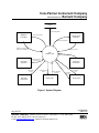
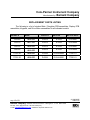
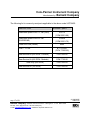
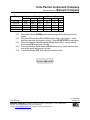
1
Cole-Parmer Instrument Company Manufactured by: Barnant Company SERVICE MANUAL MODELS: 7523-60 7523-70 7550-30 7550-50 77301-20 77301-30 Masterflex Digital L/S® Drive System: Standard Console, 115/230 Vac, 10 to 600 r/min Standard Console, 115/230 Vac, 1.6 to 100 r/min Computerized Console, 115/230 Vac, 10 to 600 r/min Computerized Console, 115/230 Vac, 1.6 to 100 r/min Benchtop Modular, 115/230 Vac, 10 to 600 r/min 77301-22 Controller 77301-21 Motor NEMA Modular, 115/230 Vac, 10 to 600 r/min 77301-23 Controller 77301-21 Motor PROPRIETARY Information contained in this manual is proprietary to the BARNANT COMPANY, division of COLE-PARMER INSTRUMENT COMPANY, INC. No reproduction for other than the intended use of maintaining the product described herein is permitted without the permission of BARNANT. BARNANT COMPANY Division of Cole-Parmer Instrument Company, Inc. 625 East Bunker Court Vernon Hills, Illinois 60061-1844 (847) 549-7600 (847) 247-2929 (Fax) 800-323-4340 Page 1 A-1299-0995 Edition 02 of 21 Barnant Company y 28W092 Commercial Avenue y Barrington, IL 847-381-7050 y 800-637-3739 y 847-381-7053 (Fax) e-mail: [email protected] y Web Site: http//www.barnant.com U.S.A. 60010-2392 Cole-Parmer Instrument Company Manufactured by: Barnant Company TABLE OF CONTENTS INTRODUCTION.......................................................................................... 3 SAFETY CONSIDERATIONS ..................................................................... 4 FUNCTIONAL DESCRIPTION .................................................................... 5 TROUBLESHOOTING ................................................................................. 9 REPAIR PROCEDURES........................................................................... 13 REPLACEMENT PARTS LISTING............................................................. 16 CALIBRATION ........................................................................................... 18 FUNCTIONAL TESTS ................................................................................ 19 ASSOCIATED DOCUMENTS .................................................................... 21 Page 2 A-1299-0995 Edition 02 of 21 Barnant Company y 28W092 Commercial Avenue y Barrington, IL 847-381-7050 y 800-637-3739 y 847-381-7053 (Fax) e-mail: [email protected] y Web Site: http//www.barnant.com U.S.A. 60010-2392 Cole-Parmer Instrument Company Manufactured by: Barnant Company INTRODUCTION Service for this product is performed at three levels: the customer, distributor/COLE-PARMER and factory/depot repair. This manual describes distributor/COLE-PARMER service procedures. Customer service procedures are described in the operator's manual. Customers are encouraged to perform service as described in the operator's manual as well as in special circumstances where special skills and safety are not considerations. To use this manual, begin with the troubleshooting section to isolate the fault to a replaceable part. The functional description and check-out procedure sections are also helpful in determining the faulty part. Distributor/COLE-PARMER repair is limited to replacement of modules as detailed in the replacement parts list section. The repair procedures section details disassembly and assembly procedures. After repair, the product should be calibrated and checked for proper performance. Please refer to the operator's manual for: A) Applications Data B) Product Description C) Installation D) Setup E) Operation F) User Calibration G) User Troubleshooting & Maintenance H) Accessories I) Specifications Page 3 A-1299-0995 Edition 02 of 21 Barnant Company y 28W092 Commercial Avenue y Barrington, IL 847-381-7050 y 800-637-3739 y 847-381-7053 (Fax) e-mail: [email protected] y Web Site: http//www.barnant.com U.S.A. 60010-2392 Cole-Parmer Instrument Company Manufactured by: Barnant Company SAFETY CONSIDERATIONS Servicing must be performed only by personnel trained and skilled in the methods of troubleshooting and repair of electromechanical products. Use of procedures other than those described in this manual may result in a safety hazard to service personnel and/or customers. When servicing any component of this unit make absolutely sure that all power to circuitry is removed. If any functional checks are to be performed while power is applied and chassis is disassembled, care must be exercised for the following: A) THIS IS A LINE OPERATED DEVICE AND IS NOT ISOLATED FROM GROUND. USE OF AN ISOLATION TRANSFORMER IS HIGHLY RECOMMENDED. B) DO NOT INADVERTENTLY SHORT ANY PART OF THE PRINTED CIRCUIT CARD TO GROUND, AS SEVERE DAMAGE WILL RESULT. Page 4 A-1299-0995 Edition 02 of 21 Barnant Company y 28W092 Commercial Avenue y Barrington, IL 847-381-7050 y 800-637-3739 y 847-381-7053 (Fax) e-mail: [email protected] y Web Site: http//www.barnant.com U.S.A. 60010-2392 Cole-Parmer Instrument Company Manufactured by: Barnant Company FUNCTIONAL DESCRIPTION The Masterflex digital peristaltic pump drive/dispenser delivers accurate amounts of fluids at adjustable flow rates. The use of a DSP with an optical shaft encoder allows the user to obtain consistent flow rates with excellent speed regulation with load, line voltage and temperature variations over the range of speed settings. The highperformance and reliable control of flow rates is accomplished through field-oriented vector control of a state-space modulated, electronically-commutated, three phase brushless permanent-magnet motor. The drive provides a nominal calibration for each available tubing size for nominal delivery rates from 0.100 to 3400 mL/min. A keypad "Calibrate" control adjusts the nominal calibration to account for variations in tubing material and mechanical tolerances. One calibration point is stored for each tubing size. For maximum flexibility, to accommodate new tubing sizes or pump types, a position (OTHER) is provided for manual calibration of the maximum flowrate. Nonvolatile memory stores the latest settings as well as current user and factory calibration points prior to power down. The drive has up to four modes of operation: operator keypad control, remote control by an external 4-20 mA current supply, or remote control by an external 0-10 V voltage supply, or, on the 7550 only, remote control by a RS-232 serial digital interface. Remote inputs and outputs are provided on the drive to easily interface to larger systems for data logging and for closed-loop process control by means of a PLC. Panel/remote operation is selected via a front panel keypad switch. Remote 4-20 mA and 0-10V inputs are provided on a "D" shell connector that is located on the rear of the unit. The connector also includes both 4-20 mA and 0-10V outputs for indicating flowrate and switch closure inputs for Remote CW/CCW, Remote Start/Stop, and Remote Prime/Purge. The "D" shell connector is replaced with a weather-resistant circular connector on the NEMA 4 drives. A hand-held control and a footswitch are available to provide optional remote Start/Stop, CW/CCW, and Prime/Purge operation. On the 7550 only there is a shrouded screw terminal block for discrete wires to provide an auxiliary contact closure input for RS-232 software sensing of limit switches and two auxiliary contact closure outputs for RS-232 software control of relays and solenoids. The operator controls and power electronics are housed in three different enclosures on three PCB assemblies. The Drive Board Assembly, consisting of a Main PCB and a Daughter PCB, has four main areas: the DSP and its related circuitry on the Page 5 A-1299-0995 Edition 02 of 21 Barnant Company y 28W092 Commercial Avenue y Barrington, IL 847-381-7050 y 800-637-3739 y 847-381-7053 (Fax) e-mail: [email protected] y Web Site: http//www.barnant.com U.S.A. 60010-2392 Cole-Parmer Instrument Company Manufactured by: Barnant Company Daughter PCB, while the remote I/O, the motor power bridge and control, and the power supply are on the Main PCB. The Display Board, mounted on the front of the enclosure and containing two dual 7-segment LED displays, is connected via a flat ribbon cable to the Daughter Board. A sealed switch keypad, containing the annunciator LED's and all the controls except the on/off switch, is mounted on the front of the enclosure. The modular and the unified console keypads have the same functions. There are three flat flex tails (switch, LED’s, and static shield ground) connecting the keypad to the Display Board. The sealed keypad is externally accessible and has a clear, green-tinted window for the display to allow modifications to the setpoint values without compromising enclosure protection. UNIFIED CONSOLE DRIVE: The same enclosure, housing the operator controls, motor, gearbox, and power electronics, is used for all console drive versions. The unit is made of a gold irridite coated aluminum, "L" shaped chassis and a four-sided ABS plastic injected molded enclosure, secured to the chassis with six screws. The enclosure has a sloped front of approximately 15°, containing the keypad and display, with a hutch for the motor to extend from the front of the enclosure. The motor is mounted to the base of the chassis. The drive board assembly with the control electronics is mounted on the right hand side. The modular style AC power cord connector with fuse, two 9-Pin “D” serial connectors (7550 only), a shrouded screw terminal block (7550 only), and a "D" series remote I/O connector are located on the rear of the chassis. The AC Power Switch is mounted to the front of the enclosure. MODULAR BENCHTOP DRIVE CONTROLLER: The modular benchtop drive enclosure, housing the operator controls and power electronics, is made of a gold irridite coated aluminum, "L" shaped chassis and a foursided ABS plastic injected molded enclosure, secured to the chassis with four screws. The enclosure has a sloped front, containing the keypad and display. The drive board assembly with the control electronics is mounted on the chassis base. The modular style AC power cord connector with fuse, power on/off switch, motor connector, and a "D" series remote I/O connector are located on the rear of the chassis. MODULAR NEMA DRIVE CONTROLLER: Page 6 A-1299-0995 Edition 02 of 21 Barnant Company y 28W092 Commercial Avenue y Barrington, IL 847-381-7050 y 800-637-3739 y 847-381-7053 (Fax) e-mail: [email protected] y Web Site: http//www.barnant.com U.S.A. 60010-2392 Cole-Parmer Instrument Company Manufactured by: Barnant Company The modular controller is housed in a painted aluminum NEMA 4 (IP56) enclosure. The drive board assembly with the control electronics is mounted on the enclosure base. The main power switch is mounted to the left of the housing in a way that preserves the waterproof feature of the unit. The power cord enters through the bottom of the housing through a water tight compression fitting, while the 25 foot motor cable and the remote control cable are attached through quick-disconnect, weather resistant connectors. The fuse is replaceable through a sealed fuse holder mounted next to the power cord. MODULAR MOTOR/DRIVE: The modular units use the same 1/10 HP BLDC motor assembly. The 6:1 gear reduction drive is capable of delivering 180 oz-in at 600 r/min. The motor accepts all short shaft L/S® Masterflex pumps. The motor attaches to a metal base for table mount. A 25 foot cable connects the motor to the controller. Page 7 A-1299-0995 Edition 02 of 21 Barnant Company y 28W092 Commercial Avenue y Barrington, IL 847-381-7050 y 800-637-3739 y 847-381-7053 (Fax) e-mail: [email protected] y Web Site: http//www.barnant.com U.S.A. 60010-2392 Cole-Parmer Instrument Company Manufactured by: Barnant Company EEPROM System Data Update Motor Control Signal PWM Module and AC Motor LED and Key Pad Sub-System Data Display and Status Module Over Temperature & Motor Over temperature Operation Command DSP AC Motor Control Measured Motor Signals Environment Tempterature System Environment Temperature Bus Double Control BUS Voltage Double Circuit Motor Signal Measurement Remote Control Output Remote Operation Command Remote Control Aux Control Input Aux Control Output Auxiliary Control Figure 1 System Diagram Page 8 A-1299-0995 Edition 02 of 21 Barnant Company y 28W092 Commercial Avenue y Barrington, IL 847-381-7050 y 800-637-3739 y 847-381-7053 (Fax) e-mail: [email protected] y Web Site: http//www.barnant.com U.S.A. 60010-2392 Cole-Parmer Instrument Company Manufactured by: Barnant Company TROUBLESHOOTING Repairs on this unit are confined to the replacement of the unit’s Main / Daughter PCB assembly, Keypad, Display PCB assembly, and/or Drive Motor assembly. Where possible, swap known good parts to localize and isolate the problem. The following is a list of possible problems and remedies: VERIFY AC POWER IS OPERATIVE. MOTOR DOES NOT ROTATE, DISPLAY DOES NOT LIGHT: 1. 2. 3. 4. 5. fuse blown unit connected to dead outlet power cord defective AC power switch failure power supply failure - replace fuse - verify supply is ON - check & replace - replace switch assembly - replace main PCB assembly UNIT BLOWS FUSES: 1. motor winding / drive failure 2. defective main PCB 3. wrong fuse installed - check using known good motor assembly - replace main PCB assembly - check fuse rating MOTOR DOES NOT ROTATE, DISPLAY LIGHTS: 1. wrong operating MODE 2. 3. 4. 5. Page 9 defective Remote Control defective keypad defective main PCB defective motor assembly - MODE set to INT for front panel operation, mA or V for remote operation - replace Remote Control - replace keypad - replace main PCB assembly - replace motor assembly A-1299-0995 Edition 02 of 21 Barnant Company y 28W092 Commercial Avenue y Barrington, IL 847-381-7050 y 800-637-3739 y 847-381-7053 (Fax) e-mail: [email protected] y Web Site: http//www.barnant.com U.S.A. 60010-2392 Cole-Parmer Instrument Company Manufactured by: Barnant Company NO REMOTE OPERATION: 1. defective Remote Control 2. defective main PCB - replace Remote Control - replace main PCB assembly NO DISPLAY OR GARBLED DISPLAY: 1. display connector not seated 2. display failure 3. defective main PCB - reseat ribbon cable (J3) - replace display PCB assembly - replace main PCB assembly IMPROPER KEYPAD OPERATION: 1. keypad failure - replace keypad. DISPLAYED ERROR CODES Err 1 Err 2 Err 3 Err 4 Err 5 Err 6 Err 7 Err 8 = Invalid encoder commutation = Motor overspeed = Over current = Bad flash checksum for program memory, can't run = Over I^2 accumulation = Not Used = Bad user setup in EEPROM, using default operator parameter values = Bad EEPROM factory cal data for analog inputs & outputs, using default A/D calibration values Err 9 = EEPROM write/verify error Err 10 = Over bus voltage, can't run Err 11 = Under bus voltage Err 12 = Motor stall Err 13 = Not Used Err 14 = Ambient over temperature Err 15 = Exceeded open loop current limit Err 16 = Phantom Interrupt, can't run Err 17 = Bad EEPROM factory cal data for encoder alignment & current, can't run Err 18 = Motor wires incorrect (only checked in encoder cal mode), can't run Page 10 A-1299-0995 Edition 02 of 21 Barnant Company y 28W092 Commercial Avenue y Barrington, IL 847-381-7050 y 800-637-3739 y 847-381-7053 (Fax) e-mail: [email protected] y Web Site: http//www.barnant.com U.S.A. 60010-2392 Cole-Parmer Instrument Company Manufactured by: Barnant Company MOTOR OVER SPEED, ERROR #2 DISPLAYED: 1. motor overshoot (no tubing in pump) 2. motor overshoot (tubing in pump) 3. defective main PCB 4. defective motor/encoder assembly - press any key to clear error - check for proper tube loading and pump operation, press any key to clear error - replace main PCB assembly - replace motor assembly MOTOR OVERLOAD, ERROR #3, #5 OR #12 DISPLAYED: 1. pump jammed - clear obstruction, press any key to clear error ERROR #7 DISPLAYED: 1. bad data 2. bad EEPROM - press any key to clear error, reprogram operator parameters - replace main PCB assembly ERROR #10 OR #11 DISPLAYED: 1. line voltage out of range - press any key to clear error, check that AC 2. defective main PCB - replace main PCB assembly line voltage is within specified range OVER TEMPERATURE, ERROR #14 DISPLAYED: 1. heat sources or obstructions for cooling - clear obstruction, allow unit to cool, press any key to clear error 2. defective main PCB - replace main PCB assembly Page 11 A-1299-0995 Edition 02 of 21 Barnant Company y 28W092 Commercial Avenue y Barrington, IL 847-381-7050 y 800-637-3739 y 847-381-7053 (Fax) e-mail: [email protected] y Web Site: http//www.barnant.com U.S.A. 60010-2392 Cole-Parmer Instrument Company Manufactured by: Barnant Company ANY OTHER ERROR DISPLAYED: 1. internal error or failure - turn unit off then on and/or press any key to reset, if any error numbers reappear then replace main PCB assy. SPECIAL KEY PRESSES 1. Press SIZE key at power up to display firmware version number. 2. Press and hold FLOW key and DIR key at power up to commission motor and drive. 3. Press MODE key at power up to set 4-20mA or 0-10V inputs and outputs. 4. To display/change motor power up option, hold STOP/START key at power up until display changes to "------" (5 seconds), keep holding STOP/START and press PRIME key 5 times. 5. To lock or unlock keypad, FLOW key is held down until display changes to '------' (5 seconds), then press PRIME key 5 times while holding down FLOW key. When keypad is locked, mode LED will blink. FOR ADDITIONAL INFORMATION REGARDING YOUR UNIT PLEASE REFER TO THE OPERATOR'S MANUAL. Page 12 A-1299-0995 Edition 02 of 21 Barnant Company y 28W092 Commercial Avenue y Barrington, IL 847-381-7050 y 800-637-3739 y 847-381-7053 (Fax) e-mail: [email protected] y Web Site: http//www.barnant.com U.S.A. 60010-2392 Cole-Parmer Instrument Company Manufactured by: Barnant Company REPAIR PROCEDURES TO DISASSEMBLE UNIT, PROCEED AS FOLLOWS: A) Disconnect AC power. B) Remove the three (console drives, two on benchtop modular drives) pan head screws on each side of the unit's cover. On NEMA drives, loosen the four captive screws in the cover. C) Lift off cover assembly. TO REASSEMBLE UNIT, PROCEED AS FOLLOWS: A) Slide on cover assembly. B) Install the three (console drives, two on benchtop modular drives) pan head screws on each side of the unit's cover. On NEMA drives, tighten the four captive screws in the cover. TO REMOVE MAIN CONTROL PCB ASSEMBLY: A) Console Drives: Remove two screws holding heat sink assembly to chassis. Remove screw from PCB Card Guide. Remove PCB Card Guide. Benchtop Modular Drives: Remove four screws holding PCB to chassis. NEMA Modular Drives: Remove two nuts holding heat sink bracket to chassis. Remove two screws holding PCB to chassis. Remove two screws holding heat sink assembly to heat sink bracket. B) Remove all cables and wires from PCB. TO REPLACE MAIN CONTROL PCB ASSEMBLY: A) Note wiring of Main Control PCB as follows: 1) BLUE of power line to: J13 Page 13 A-1299-0995 Edition 02 of 21 Barnant Company y 28W092 Commercial Avenue y Barrington, IL 847-381-7050 y 800-637-3739 y 847-381-7053 (Fax) e-mail: [email protected] y Web Site: http//www.barnant.com U.S.A. 60010-2392 Cole-Parmer Instrument Company Manufactured by: Barnant Company 2) BROWN of power line to: J12 3) GREEN/YELLOW of power line to J15 4) BLACK of drive motor to: J9 5) WHITE of drive motor to: J10 6) RED of drive motor to: J11 7) Remote I/O Connector ribbon cable to: J7 8) Auxiliary I/O cable to J4 (7550 Only) B) Note wiring of Daughter PCB as follows: 1) Cable from Motor Encoder to: J4 2) Ribbon cable from Display PCB to: J3 C) Before using the unit, a new Motor and/or Drive Assembly must be commissioned. Without a pump head attached, press and hold the FLOW key and the DIR key while powering up. Release the keys when the display blanks. After all LED’s and display segments illuminate, press the START/STOP key. Display will change to CALE, and the CAL LED will flash. The motor will run at slow speed for a few seconds and then stop. The display will change to ETST, and the motor will run again for a few seconds. When the display changes to CAL, press any key except MODE. TO REPLACE MOTOR / ENCODER ASSEMBLY (Console Drives Only): A) B) C) D) E) F) G) H) Remove BLACK motor lead from J9. Remove WHITE motor lead from J10. Remove RED motor lead from J11. Remove Cable from Motor Encoder. Remove top nut holding GREEN ground wire to the chassis. Loosen two bolts holding motor to chassis. Replace motor and tighten bolts. Attach leads and encoder cable. Follow step C in “TO REPLACE MAIN CONTROL PCB ASSEMBLY”. Page 14 A-1299-0995 Edition 02 of 21 Barnant Company y 28W092 Commercial Avenue y Barrington, IL 847-381-7050 y 800-637-3739 y 847-381-7053 (Fax) e-mail: [email protected] y Web Site: http//www.barnant.com U.S.A. 60010-2392 Cole-Parmer Instrument Company Manufactured by: Barnant Company TO REMOVE DISPLAY PCB: A) Remove 4 screws (console drives, 3 on benchtop and NEMA modular drives) holding the PCB to cover. B) Remove ribbon cables. The ZIF sockets release the keypad flex tails by sliding out. TO REPLACE DISPLAY PCB: A) Replace cables. The ZIF sockets secure the keypad flex tails by sliding in. 1) 2) 3) 4) Ribbon Cable (26 conductor) from Main Control PCB J3. LED (11 conductor) flex tail from Keypad J2. Switch (7 conductor) flex tail from Keypad J3. Shield ground flex tail from Keypad – Secured and grounded to Display PCB with mounting screw. B) Secure Display PCB with 4 screws (console drives, 3 on benchtop and NEMA modular drives). TO REPLACE KEYPAD: A) Follow the steps outlined in "REMOVE DISPLAY PCB". B) Peel keypad from cover. C) Affix new keypad to cover. D) Follow the steps outlined in "REPLACE DISPLAY PCB". Page 15 A-1299-0995 Edition 02 of 21 Barnant Company y 28W092 Commercial Avenue y Barrington, IL 847-381-7050 y 800-637-3739 y 847-381-7053 (Fax) e-mail: [email protected] y Web Site: http//www.barnant.com U.S.A. 60010-2392 Cole-Parmer Instrument Company Manufactured by: Barnant Company REPLACEMENT PARTS LISTING The following is a list of stocked Main / Daughter PCB assemblies, Display PCB assemblies, Keypads, and Drive Motor assemblies for all indicated models: MODEL # MAIN DISPLAY KEYPAD MOTOR ASSY 7523-60 8116-CR D-2974 E-2222 7812-0001 7523-70 8117-CR D-2974 E-2222 7812-0002 7550-30 8118-CR D-2974 E-2325 7812-0001 7550-50 8119-CR D-2974 E-2325 7812-0002 77301-20 8120-CR D-3224 E-2544-0003 77301-21 77301-30 8120-CR D-3224 E-2544-0001 77301-21 Page 16 A-1299-0995 Edition 02 of 21 Barnant Company y 28W092 Commercial Avenue y Barrington, IL 847-381-7050 y 800-637-3739 y 847-381-7053 (Fax) e-mail: [email protected] y Web Site: http//www.barnant.com U.S.A. 60010-2392 Cole-Parmer Instrument Company Manufactured by: Barnant Company The following list is commonly used parts applicable to the above model LISTINGS: DESCRIPTION BARNANT part # Detachable power cord 115 Vac (USA) B-3115 (C/P# 50001-68) Detachable power cord 230 Vac (EUROPEAN) B-2938 (C/P# 50001-70) Fixed Line Cord (NEMA) Fuse – T3.15A B-1115-0057 (C/P # 77500-25) Gear Service Kit (600 RPM - Console) C/P# 7553-06 Gear Service Kit (600 RPM - Modular) C/P# 77300-01 Gear Only (600 RPM) Gear Service Kit (100 RPM) Page 17 8094 C/P# 7553-09 C/P# 7553-08 A-1299-0995 Edition 02 of 21 Barnant Company y 28W092 Commercial Avenue y Barrington, IL 847-381-7050 y 800-637-3739 y 847-381-7053 (Fax) e-mail: [email protected] y Web Site: http//www.barnant.com U.S.A. 60010-2392 Cole-Parmer Instrument Company Manufactured by: Barnant Company CALIBRATION Due to the design of this product, there are no calibrations and/or adjustments to be performed other than set-ups performed by the customer. Calibration of the Analog I/O requires a special calibration fixture at the factory. Additional technical specifications are available in the unit's OPERATORS MANUAL. Page 18 A-1299-0995 Edition 01 of 21 Barnant Company y 28W092 Commercial Avenue y Barrington, IL 847-381-7050 y 800-637-3739 y 847-381-7053 (Fax) e-mail: [email protected] y Web Site: http//www.barnant.com U.S.A. 60010-2392 Cole-Parmer Instrument Company Manufactured by: Barnant Company FUNCTIONAL TESTS 1.00 Test equipment required: 1.01 1.02 1.03 2.00 TESTING: 2.01 2.02 2.03 2.04 2.05 2.06 2.07 2.08 2.09 2.10 2.11 Page 19 Contact Tachometer (C-P Cat. # 8203-50 or 8203-80) Variac 115 VAC, 60Hz or 230 VAC, 50Hz. Foot switch (C-P Cat. # 7595-42) or Remote Control (C-P Cat. # 7592-83) Plug controller into the variac set to 115 volts ac or 230 volts. Turn the main power switch to the ON position. Verify that all LED’s, display segments, and decimal points illuminate. Verifying each LED illuminates for INT, mA, and V, press the MODE switch to get to the INT mode. Select any tubing size (not RPM), then press the FLOW switch. The displayed value should change. Press the CAL switch. Note that the annunciator LED next to the switch is flashing. Press the tubing SIZE switch to exit out of CAL. Verifying the LED for each tubing illuminates, press the tubing SIZE switch to get the RPM display. Verifying each LED illuminates for mL, COPY, and SEC, press the DISPense/copy switch until none of the LED's is on. Verifying each LED illuminates for CW and CCW, set the drive to the CW direction with the motor DIRection switch. Turn the drive OFF. While holding the MODE switch, turn the drive ON. Set the input to 4-20mA with the increment (^) or decrement (v) switches. Press the MODE switch. Set the output to 4-20mA with the increment (^) or decrement (v) switches. Press the MODE switch to get to the INT mode. Turn the drive OFF then ON after a wait of at least five seconds. Verify the INT, CW, and RPM indicators remain lit. Press START/STOP to start drive and then press ^ until display reads the maximum setting. Using the hand tach, verify motor runs within the specified tolerance. NOTE: Motor should be rotating CW when viewed from the front. Press v until display reads the minimum setting. Using the hand tach, verify motor runs within the specified tolerance. A-1299-0995 Edition 01 of 21 Barnant Company y 28W092 Commercial Avenue y Barrington, IL 847-381-7050 y 800-637-3739 y 847-381-7053 (Fax) e-mail: [email protected] y Web Site: http//www.barnant.com U.S.A. 60010-2392 Cole-Parmer Instrument Company Manufactured by: Barnant Company Drive 7523-60 7523-70 7550-30 7550-50 77301-ALL 2.12 2.13 2.14 2.15 2.16 Maximum Speed Setting Max. Min. 600 603 597 100 100.5 99.5 600 603 597 100 100.5 99.5 600 603 597 Minimum Speed Setting Max. Min. 10 11 9 1.6 1.9 1.3 10 11 9 1.6 1.9 1.3 10 11 9 Press and hold the PRIME switch while noting that the drive runs at full speed. Press the Remote Start/Stop (NEMA drives only) or foot switch. Verify that the drive runs as long as it is held. Press START/STOP to start drive. Press the Remote Fwd/Rev switch (NEMA drives only). Verify that the drive runs CCW as long as it is held. Press the Remote Prime switch (NEMA drives only). Verify that the drive runs at full speed as long as it is held. Turn the controller OFF and unplug it from the variac. ************************** TESTS COMPLETED *********************** Page 20 A-1299-0995 Edition 01 of 21 Barnant Company y 28W092 Commercial Avenue y Barrington, IL 847-381-7050 y 800-637-3739 y 847-381-7053 (Fax) e-mail: [email protected] y Web Site: http//www.barnant.com U.S.A. 60010-2392 Cole-Parmer Instrument Company Manufactured by: Barnant Company ASSOCIATED DOCUMENTS Current copies of the following documents are required for servicing the drive: Operator’s Manual: Assembly Drawings: 7523-ALL (Chassis): 7550-ALL (Chassis): 77301-20/22 (Chassis): 77301-30/23 (Final): 77301-30/23 (Bottom): Page 21 A-1299-0996 7814 7815 7817 7818 7819 A-1299-0992 Edition 01 of 21 Barnant Company y 28W092 Commercial Avenue y Barrington, IL 847-381-7050 y 800-637-3739 y 847-381-7053 (Fax) e-mail: [email protected] y Web Site: http//www.barnant.com U.S.A. 60010-2392