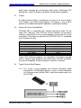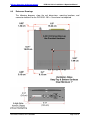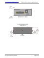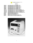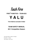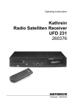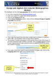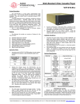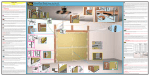
1
Installation and Operation
Manual
DVD-9101-201-x
Serial Digital Video Disc Player
Document # 540339
7300 Industry Drive, North Little Rock, AR 72117
Phone: 501-955-2929 Fax: 501-955-2988
www.decraneaerospace.com
DeCrane Aerospace Audio International
DVD-9101-201-x Installation & Operation Manual
Document Revision History
Rev. Level
IR
A
Date
11/2006
02/2008
B
06/2009
Description
Initial Release
Updated Outline Drawings corrected -2 connector mating part #
Updated logo, website, & company name change
Corrected Table of Illustrations & Table of Contents
Added cover bezel information
Replaced 2.4.1 & 2.4.2 Block Diagram images with correct ones
Added Fahrenheit to 3.3.11 and to 3.7.1 Electrical Table
Corrected 3.7.1 Electrical Power Requirements
Corrected Outline Numbers for 3.4.5, 3.4.5, 3.7.4, 4.3, 7.1
Added missing 7.0 Reference Drawing
Corrected dimensions for 6.0 Specifications Table
Changed Pinout # 3 Description from “No Connect” to “Reserved”
Corrected grammatical errors
Added recommendation to terminate unused outputs with a 75ohm load, Section 3.4.4
Added recommendation to use EMI hood, Sections 3.4.4 & 3.8
Updated bonding strap requirement, Section 3.4.4
Updated wiring specification for digital audio to show
recommended cable impedance, Section 3.4.5
Separated Instructions for Continued Airworthiness &
Troubleshooting, Sections 5.0 & 6.0
Included Environmental Qualification Data, Section 9.0
Reference Documents
(or latest revision)
Description
Document #
525859 Rev IR1
DVD-9101-201-x Outline Drawing
Service Bulletin List
Service
Bulletin #
Subject
Manual
Revision
Revision
Date
Table of Illustrations
Section #
Description
Page #
2.4
Typical System Block Diagram
5
4.1
Front Panel Controls
13
7.0
Reference Drawings
23-24
INFORMATION NOTICE: Despite any other copyright notice, this document and information disclosed
herein contains confidential, proprietary designs owned by DeCrane Aerospace Audio International.
Neither this document nor the data contained herein shall be reproduced, used, or disclosed to anyone
without the written authorization of DeCrane Aerospace Audio International.
Document # 540339, Rev B, 06/2009
Page 1 of 25
DeCrane Aerospace Audio International
DVD-9101-201-x Installation & Operation Manual
Table of Contents
Section
1.0
1.1
1.2
1.3
1.4
Description
General Information. . . . . . . . . . . . . . . . . . . . . . . . . . . . . . . .
Introduction . . . . . . . . . . . . . . . . . . . . . . . . . . . . . . . . . . . . . . .
Purpose of the Equipment . . . . . . . . . . . . . . . . . . . . . . . . . . . .
Operational Features . . . . . . . . . . . . . . . . . . . . . . . . . . . . . . . .
Optional Equipment . . . . . . . . . . . . . . . . . . . . . . . . . . . . . . . . .
Page
3
3
3
3
4
2.1
2.2
2.3
2.4
Application. . . . . . . . . . . . . . . . . . . . . . . . . . . . . . . . . . . . . . .
Typical Application . . . . . . . . . . . . . . . . . . . . . . . . . . . . . . . . . .
Display . . . . . . . . . . . . . . . . . . . . . . . . . . . . . . . . . . . . . . . . . . .
Media and Format Capabilities. . . . . . . . . . . . . . . . . . . . . . . . .
Typical System Block Diagram . . . . . . . . . . . . . . . . . . . . . . . .
4
4
5
5
5
3.0
Installation. . . . . . . . . . . . . . . . . . . . . . . . . . . . . . . . . . . . . . .
3.1 Preparation. . . . . . . . . . . . . . . . . . . . . . . . . . . . . . . . . . . . . . . .
3.2 Unpacking and Inspection. . . . . . . . . . . . . . . . . . . . . . . . . . . . .
3.3 Cautions & Warnings. . . . . . . . . . . . . . . . . . . . . . . . . . . . . . . .
3.4 Wiring Requirements. . . . . . . . . . . . . . . . . . . . . . . . . . . . . . . .
3.5 Physical Characteristics. . . . . . . . . . . . . . . . . . . . . . . . . . . . . .
3.6 Clearance and Separation Requirements. . . . . . . . . . . . . . . . .
3.7 Electrical Characteristics. . . . . . . . . . . . . . . . . . . . . . . . . . . . .
3.8 Mating Connector Information. . . . . . . . . . . . . . . . . . . . . . . . . .
3.9 Pinout Assignments and Descriptions. . . . . . . . . . . . . . . . . . . .
3.10 Post Installation Test. . . . . . . . . . . . . . . . . . . . . . .. . . . . . . . . .
6
6
7
7
8
9
10
10
11
11
12
4.0
Operation. . . . . . . . . . . . . . . . . . . . . . . . . . . . . . . . . . . . . . . .
Front Panel Controls. . . . . . . . . . . . . . . . . . . . . . . . . . . . . . . . .
Control Functions. . . . . . . . . . . . . . . . . . . . . . . . . . . . . . . . . . .
Supported RS-485 and IR Commands. . . . . . . . . . . . . .
13
13
14
17
5.0
Instructions for Continued Airworthiness. . . . . . . . . . . . . .
20
6.0
Troubleshooting . . . . . . . . . . . . . . . . . . . . . . . . . . . . . . . . . .
General Troubleshooting Procedures. . . . . . . . . . . . . . . . . . .
Troubleshooting Chart. . . . . . . . . . . . . . . . . . . . . . . . . . . . . . .
20
20
22
7.0
Specifications. . . . . . . . . . . . . . . . . . . . . . . . . . . . . . . . . . . . .
22
8.0
Reference Drawings. . . . . . . . . . . . . . . . . . . . . . . . . . . . . . . .
23
9.0
Environmental Qualification Data . . . . . . . . . . . . . . . . . . . .
25
2.0
4.1
4.2
4.3
6.1
6.2
Document # 540339, Rev B, 06/2009
Page 2 of 25
DeCrane Aerospace Audio International
DVD-9101-201-x Installation & Operation Manual
DVD-9101-201-x
Serial Digital Video Disc Player
1.0
General Information
1.1
Introduction
This manual contains information for the proper installation and operation
of DeCrane Aerospace Audio International’s (DAAI) Digital Video Disc
Player, Model # DVD-9101-201-x. The “-x” suffix in the model number
designates the type of connector utilized; “-1” = Positronic and “-2” =
D-Subminiature. Also included are mechanical and electrical
characteristics of the unit.
1.2
Purpose of the Equipment
DeCrane Aerospace Audio International’s DVD-9101-201-x is a small
form-factor DVD Player compatible in size to current DeCrane Aerospace
Audio International Single-Disc Players.
The DVD-9101-201-x contains three (3) SDI video outputs and three (3)
AES-3 audio output channels. Audio, video, and control commands are
handled via DAAI’s RS-485 data bus. This device is designed to interface
with equipment containing DAAI Serial Digital video and AES-3 audio
equipment and is provided with power and ID strapping connections.
This unit incorporates four (4) ID strapping connections to allow up to 16
like units to operate concurrently on the same RS-485 serial data bus
segment independently of each other.
1.3
Operational Features
Supports standard commercial CD, DVD, and MP3 audio
Optional IR control
Three (3) SDI video outputs and three (3) AES-3 audio 2-channel
outputs or AES-3 audio 5.1 channel output
Supports all DVD region codes for international operation
Easy-to-use front panel controls
Up to 45 advanced functions available
Hand held remote or any DAAI data bus device for complete
system customization
Full range frequency response
Document # 540339, Rev B, 06/2009
Page 3 of 25
DeCrane Aerospace Audio International
DVD-9101-201-x Installation & Operation Manual
Nine (9) language and subtitle options (dependent upon usersupplied disc capabilities)
Easy to mount and connect
Compact, lightweight package
Four (4) Forward and Reverse accelerated scanning speeds with
DVD video
Three (3) Slow, Forward, and Reverse speeds with DVD video
Internal test signal generation for convenient device validation,
system set-up, and system troubleshooting
1.4
Optional Equipment
The DVD-9101-201-x is optionally controlled by DAAI infrared remote or
touch screen panels, and it is important to remember that some remote
controls possess functions not duplicated by the unit’s front panel buttons,
such as Menu and Set-Up. While the DVD-9101-201-x is a complete and
fully functional standalone DVD Player, it is strongly recommended that a
remote control device also be employed for thorough enjoyment of the
unit.
DeCrane Aerospace Audio International also offers a wide variety of
equipment that will perfectly complement the DVD-9101-201-x and will
also be valuable and attractive additions to any cabin interior.
An optional cover bezel DVDKIT-9101-101-1 may be ordered to match the
interior style of any aircraft. The cover bezel is not an integral part of the
player and must be ordered as a separate item. Contact your DeCrane
Aerospace Audio International representative for details.
2.0
Application
2.1
Typical Application
Typical Audio Output (AES-3 digital audio) interfaces include various
AES-3 distribution and/or signal manipulation devices. This unit is capable
of interfacing and providing output to compatible DeCrane Aerospace
Audio International devices capable of distributing and/or processing the
source output digital audio including, but not limited to: Audio routers,
stand-alone AES-3 decoders, and audio power amplifiers with built-in
AES-3 decoding capability.
Typical Video Output (SMPTE-259M Standard Definition-Serial Digital
Interface) interfaces include various SD-SDI distribution and/or signal
manipulation devices. This unit is capable of interfacing and providing
output to compatible DeCrane Aerospace Audio International SD-SDI
devices capable of distributing and/or deserializing the source output
Document # 540339, Rev B, 06/2009
Page 4 of 25
DeCrane Aerospace Audio International
DVD-9101-201-x Installation & Operation Manual
digital video including, but not limited to: SDI routers, Stand-alone SDI
deserializers, and LCD displays with built-in SDI deserialize capability.
2.2
Display
An eight-character display is provided on the front of the unit to display
Title, Chapter, and Track during playback. The display is also used to
provide user feedback during other operations including disc loading.
2.3
Media and Format Compatibilities
DVD-9101-201-x is compatible with standard commercial audio CD and
video DVD. Note that since DVD disc format standards are constantly
evolving, some DVD discs may not play properly or may cause the unit to
malfunction. DAAI does not guarantee the DVD-9101-201-x is compatible
with all media or formats.
Compatible Formats
Standard DVD-Video
DVD-R/-RW, DVD+R/+RW
Video CD, SVCD
Standard CD-Digital Audio
DVD[Plus]
MP3, WMA9
Standard CD-Recordable
Standard CD-ReWriteable
DVD-Audio
SACD, CD layer only
Dual disc
JPEG
Typical DVD authoring programs are compatible and produce playable
movies. However some programs may create menu structures or controls
that are not compatible, or do not display or function as intended.
2.4
Typical System Block Diagram
2.4.1 This system is fully compatible with DeCrane Aerospace Audio
International’s RS-485 digital data bus system. It can be configured
for IR remote control utilizing DAAI’s hand held remote control unit
and IFR-485.
Document # 540339, Rev B, 06/2009
Page 5 of 25
DeCrane Aerospace Audio International
DVD-9101-201-x Installation & Operation Manual
2.4.2 The unit can also be configured for Touch Screen or remote panel
control (i.e. entertainment control panels). The panels are on
DAAI’s RS-485 digital data bus system and configured to control
the operational features of the DVD-9101-201-x.
3.0
Installation
3.1
Preparation
3.1.1 Careful consideration of the location of this and all other
audio/visual modules is necessary. Some of the items to be
considered in the design and layout of the aircraft cabin include:
• Space
• Available power supply
• Environmental conditions (temperature, humidity, etc.)
• Length of cable runs
• Location of other aircraft systems (oxygen delivery)
3.1.2 The DVD-9101-201-x shall be installed to conform to the standards
designated by the customer, installing agency, and existing
conditions as to the unit location and type of installation.
3.1.3 Mounting screws are required to secure the unit. Mounting
provisions are provided via four (4) 10-32 UNF-2B threaded
mounting holes – two (2) on the left and right sides of unit. Refer to
Section 7.0, Reference Drawings, for illustrations.
3.1.4 The installing agency shall supply and fabricate all external cables
to the DVD-9101-201-x. The length and routing of external cables
shall be carefully studied and planned before attempting installation
of the unit. Allow adequate space for installation of cable and
connectors. Mating connectors are the responsibility of the
Document # 540339, Rev B, 06/2009
Page 6 of 25
DeCrane Aerospace Audio International
DVD-9101-201-x Installation & Operation Manual
installing agency. Correct pin assignments as outlined in Section
3.8 are the responsibility of the installing agency.
3.2
Unpacking and Inspection
3.2.1 Carefully open the packaging and remove the DVD-9101-201-x.
Verify that all components have been included in the package per
the packing list. Inspect the unit for shipping damage.
3.2.2 If damage has occurred during shipping, a claim should be filed
with DeCrane Aerospace Audio International WITHIN 24 hours and
a Return Request Authorization Number shall be obtained from
DAAI by contacting the Repair Department at 501.801.8101.
Repackage the unit in its original packaging materials and return it
to DAAI following instructions given by the DAAI representative.
Refer to the front cover of this manual for address. If no return is
necessary, retain the packing list and the packing materials for
storage.
3.3
Cautions & Warnings
3.3.1 It is important to do a pin-to-pin power and ground check on all
connectors. Ensure that power and ground are applied only where
specified. Damage to the unit may result if power or ground is
applied to the wrong points.
3.3.2 DO NOT connect or disconnect the unit while power is applied.
3.3.3 DO NOT remove any factory-installed screws. Damage to the unit
may result and void any warranties.
3.3.4 DO NOT drop the unit or subject it to strong shock. The unit
contains glass parts that may break or crack.
3.3.5 DO NOT place foreign objects into openings. Contact with foreign
objects may result in dangerous voltage or electric shock.
3.3.6 DO NOT place near strong magnetic fields, radiators or other heat
sources.
3.3.7 DO NOT use this unit other than for its intended purpose. Doing so
might lead to electric shock or injury.
3.3.8 DO NOT use near water, moisture, or volatile sprays. Do not use
any type of solvent when cleaning (surface damage may occur).
Document # 540339, Rev B, 06/2009
Page 7 of 25
DeCrane Aerospace Audio International
DVD-9101-201-x Installation & Operation Manual
3.3.9 DO NOT expose unit to sun or bright light.
3.3.10 The chassis material and structural design of this unit is such that
the unit is not capable of containing fire within the unit. This unit
does not provide for waterproof operation.
3.3.11 Operating temperature should not exceed:
+5°° to +131°° F
–15°° to +55°° C
3.3.12 ESD (Electro Static Discharge) guidelines shall be followed.
3.4
Wiring Requirements
3.4.1 Introduction
The installing agency shall supply and fabricate all external cables.
The length and routing of external cables shall be carefully studied
and planned before attempting installation of the equipment. Allow
adequate space for installation of cable and connectors.
3.4.2 Power Wires
Power and Ground wires shall be in accordance with M22759 or
equivalent.
3.4.3 Bonding
The grounding lug shall be electrically bonded to the aircraft
structure using a braided copper bonding strap with <0.01
resistance from the DVD to the aircraft frame.
3.4.4 Video Lines
All serial digital video wiring connections are recommended to use
PIC V76261 shielded coax. Serial digital video provided in SMPTE
259M format. All connector types shall be compatible with abovelisted wiring requirements.
It is recommended to terminate any unused video outputs with a
75-ohm load inside the aircraft side mating connector.
Document # 540339, Rev B, 06/2009
Page 8 of 25
DeCrane Aerospace Audio International
DVD-9101-201-x Installation & Operation Manual
It is recommended to use a metal EMI hood, i.e. part number
D37000ANVL0 or D37000ANE0 from Positronic Industries or
equivalent, for the connector backshell. The shield of the coaxial
cable should be connected to the bonding point inside the EMI
hood by soldering a ¼” braided bonding strap to the shield side of
the size-8 contact where the contact meets the cable and
electrically connecting to the bonding point inside the hood.
3.4.5 Serial Digital Audio Wiring
All AES3 digital audio connections are recommended to use
twisted shielded cable with a cable impedance of 110
+/- 10%
and the shield properly grounded at the source end. Twisted
shielded cable shall be 22 AWG (minimum) and shall be in
accordance with NEMA WC 27500.
3.4.6 RS-485 Data Bus Wiring
The DVD-9101-201-x is designed to interface with other DeCrane
Aerospace Audio International equipment via DAAI’s proprietary
RS-485 serial data bus. The data bus shall be implemented using a
twisted shielded pair cable in accordance with NEMA WC 27500.
The wire size for the conductors in this cable shall be 22 AWG,
MINIMUM. Shield pins are available for connecting data bus
shields when required. Refer to DAAI document 650007 for RS-485
serial data bus design architecture.
3.5
Physical Characteristics
3.5.1 Refer to Section 8.0 for unit dimensions and attachment points.
3.5.2 When mounting the unit, allow sufficient space for mating
connectors.
3.5.3 Chassis material is 6061-T6 aluminum, clear of anodization while
maintaining electrical conductivity to ground from any point on the
chassis via gold irridite treatment, per MIL-C-5541.
3.5.4 This unit has an internal fan and ventilation holes in the chassis for
cooling. Installation recommendation requires 1-inch spacing from
other components and structures except the mounting surface for
which the unit should be in direct contact.
3.5.5 Bonding between chassis mounting point and airframe installation
to be <0.01 resistance using a braided copper bonding strap. No
Document # 540339, Rev B, 06/2009
Page 9 of 25
DeCrane Aerospace Audio International
DVD-9101-201-x Installation & Operation Manual
surface prep is required due to conductive chassis finish (except
front bezel).
3.6
Clearance and Separation Requirements
When running cables, avoid sharp bends and placing cables near aircraft
control cables. Maintain a MINIMUM clearance of three (3) inches from
any control cable. If wiring is run parallel to combustible fluid or oxygen
lines, maintain a separation of six (6) inches between the lines.
3.7
Electrical Characteristics
3.7.1 Electrical Specifications:
Electrical
Nominal Power
Maximum Power
Operating Voltage
Range
Data Bus Type
Serial Digital Interface
Audio Interfaces
IR Signal
Operating Temperature
Storage Temperature
600mA @ +28 VDC
900mA @ +28 VDC
+18 to +32 VDC
AI RS-485
270 Mb/s per SMPTE-259M
three outputs
AES-3 digital audio outputs
three outputs
5V active low
+5° to +131° F
-15° to +55° C
-4° to +176° F
-20° to +80° C
3.7.2 The DVD-9101-201-x utilizes one (1) 25-pin connector for electrical
connections, which provides power, data bus control, infrared input,
and four (4) address strapping pins and a strapping common for
unit identification on the RS-485 data bus and for IR control.
3.7.3 Infrared input provides a ground reference connection (-). For
optimum infrared signal transmission, this ground reference should
connect to the IFR-485 module being utilized.
3.7.4 The four (4) address strap pins are able to be connected to the
strap common. This provides 16 strapping configurations, allowing
up to 16 identical units to be individually controlled on a system.
Document # 540339, Rev B, 06/2009
Page 10 of 25
DeCrane Aerospace Audio International
3.8
DVD-9101-201-x Installation & Operation Manual
Mating Connector Information
Model #
DVD-9101-201-1
DVD-9101-201-2
Mating Connector
CBC25W3F140000 or equivalent
(Positronic Industries)
Size 8 Contacts: 110236 (x3) (PIC Wire & Cable)
3025W3SXK99A1OX Female Plug w/ male
jackscrews or equivalent
(American Conec Corporation)
Size 8 Contacts: 110236 (x3) (PIC Wire & Cable)
Note: It is recommended to use a metal EMI hood, i.e. part number
D37000ANVL0 for slidelock or D37000ANE0 for jackscrew from Positronic
Industries or equivalent, for the connector backshell.
3.9
Pinout Assignment and Descriptions
DVD-9101-201-x
Pin #
Description
1
+28 VDC Power Input
2
Circuit Ground
3
Reserved
4
RS-485 Serial Data Bus A (HI)
5
RS-485 Serial Data Bus B (LO)
6
RS-485 Serial Data Bus SHIELD
7
ID Common
8
ID 0
9
ID 1
10
ID 2
11
ID 3
12
Pause Input
13
Infrared Digital Input
14
AES3 Audio Output #1 +
15
AES3 Audio Output #1 –
16
AES3 Audio Output #1 SHIELD
17
AES3 Audio Output #2 +
18
AES3 Audio Output #2 19
AES3 Audio Output #2 SHIELD
20
AES3 Audio Output #3 +
21
AES3 Audio Output #3 22
AES3 Audio Output #3 SHIELD
A1
SD-SDI Video Output # 1
A2
SD-SDI Video Output # 2
A3
SD-SDI Video Output # 3
Document # 540339, Rev B, 06/2009
Page 11 of 25
DeCrane Aerospace Audio International
3.10
DVD-9101-201-x Installation & Operation Manual
Post Installation Test
This section is designed to assist the user in determining whether the
DVD Player has been properly installed. First, before applying power,
ensure the unit is connected correctly, especially concerning Power and
Ground wiring. The audio signal output of the unit is generally connected
to cabin speaker systems in addition to headphone locations. Verify all
connections before supplying power to the unit.
There are no ON/OFF controls on the unit so ensure that +28 VDC power
has been connected. Normally if power is not properly connected, the
front panel controls’ backlighting will not be illuminated and the player will
not respond to any commands. If power is properly connected, the AI logo
will appear on the monitor screen.
Activate monitors and speakers from the appropriate control panels. Audio
will be supplied through headphones and/or speakers per system design.
Make certain that the monitor(s) connected to the DVD Player are on and
functional.
Be certain to load the disc correctly—if the DVD has a sticker, it
should be loaded with the sticker facing up! Gently push the into the
DVD slot. The DVD unit will accept the DVD and pull it inside.
Insert
Disc
Here
The disc should begin loading, which will be indicated on the monitor
screen. If the disc does not start playing automatically after it has loaded,
then use the DVD Player’s front panel buttons or the handheld remote
control unit to select PLAY. DVD material should appear on the
appropriate monitor. This material is usually a menu, but this may vary,
depending on individual DVD configuration. For CDs, the tracks should be
listed on the side of the screen. Audio should channel through the
speaker/headphone system.
Document # 540339, Rev B, 06/2009
Page 12 of 25
DeCrane Aerospace Audio International
DVD-9101-201-x Installation & Operation Manual
If sound cannot be immediately heard through speakers or headphones, it
may be that the volume is too low and should be increased appropriately.
Note that there are no audio controls on the DVD-9101-201-x. Any
desired adjustments must be performed through other audio distribution
devices.
If power is interrupted (>200 msec) or power drops below +18 VDC while
a disc is playing, the player may shut down. If a DVD disc is in the player,
the unit will begin playback from the beginning of the disc automatically.
4.0
Operation
4.1
Front Panel Controls
From left to right, the buttons are:
PLAY
REVERSE SKIP (top)
PAUSE
STOP
FORWARD SKIP (bottom)
EJECT
Document # 540339, Rev B, 06/2009
Page 13 of 25
DeCrane Aerospace Audio International
4.2
DVD-9101-201-x Installation & Operation Manual
Control Functions:
EJECT BUTTON
The EJECT Button allows the user to eject the DVD. Pressing the EJECT Button
will allow the user to gently pull the DVD out of the mechanism.
PLAY BUTTON
The PLAY Button allows the user to begin or resume normal playback when the
DVD Player is in the following modes: Stop, Pause, Fast Forward, Fast Reverse,
Slow Forward, and Slow Reverse. See the following pages for details on these
modes.
In lieu of remote or RS-485 commands, the user can press and hold the PLAY
Button for approximately five (5) seconds to access the DVD’s Media Menu. The
PLAY Button acts also as an "ENTER" Button when selecting menu options.
REVERSE SKIP BUTTON
During movie or audio play, press to skip to the beginning of the Previous
Chapter or Track. Press and hold for approximately one (1) second to enter
FAST REVERSE (x8) Mode. Also used to navigate (as Left curser) in DVD’s
Media Menu. Press and hold for approximately five (5) seconds to navigate as
Up curser in DVD’s Media Menu.
REVERSE BUTTON (Not a front panel button. This feature is found on
remotes and data bus connected devices only)
The FAST/SLOW REVERSE Button is functionally dependent on the current
mode of the DVD Player, and the media type being played.
DVD VIDEO – FAST REVERSE: This button is used during normal playback
mode.
Pressing the REVERSE Button once will place the DVD Player in FAST
REVERSE x2 Mode with no audio output.
Pressing the REVERSE Button a second time will place the DVD Player in
FAST REVERSE x4 Mode with no audio output.
Document # 540339, Rev B, 06/2009
Page 14 of 25
DeCrane Aerospace Audio International
DVD-9101-201-x Installation & Operation Manual
Pressing the REVERSE Button a third time will place the DVD Player in FAST
REVERSE x8 Mode with no audio output.
Pressing the REVERSE Button a fourth time will place the DVD Player in
FAST REVERSE x32 Mode with no audio output.
Pressing the REVERSE Button a fifth time will cycle the FAST REVERSE
Mode back to PLAY.
Pressing the PLAY Button will exit the current FAST REVERSE Mode and
return the DVD Player to normal playback.
FORWARD SKIP BUTTON
DVD VIDEO – FORWARD: During movie or audio play, press to skip to the
beginning of the Next Chapter or Track. Press and hold for approximately one (1)
second to enter Fast Forward (x8) Mode. Also used to navigate (as Right curser)
in DVD’s Media Menu. Press and hold for approximately five (5) seconds to
navigate as a Down curser in DVD’s Media Menu.
FORWARD BUTTON (Not a front panel button. This feature is found on
remotes and data bus connected devices only)
The FORWARD Button is functionally dependent on the current mode of the
DVD Player, and the media type played.
Pressing the FORWARD Button once will place the DVD Player in FAST
FORWARD x2 Mode.
Pressing the FORWARD Button a second time will place the DVD Player in
FAST FORWARD x4 Mode.
Pressing the FORWARD Button a third time will place the DVD Player in
FAST FORWARD x8 Mode.
Pressing the FORWARD Button a fourth time will place the DVD Player in
FAST FORWARD x32 Mode.
Pressing the FORWARD Button a fifth time will cycle the FAST FORWARD
Mode back to FAST FORWARD x2 Mode.
Pressing the PLAY Button will exit the current FAST FORWARD Mode and
return the DVD Player to normal playback.
Document # 540339, Rev B, 06/2009
Page 15 of 25
DeCrane Aerospace Audio International
DVD-9101-201-x Installation & Operation Manual
PAUSE BUTTON
DVD VIDEO – PAUSE: Press the PAUSE Button once to place the DVD Player
in PAUSE Mode. Several functions become available when the DVD Player is in
PAUSE Mode:
The user can enter SLOW REVERSE Mode by pressing the REVERSE
Button. (Not a front panel option. This function is accessible by remotes and
data bus connected devices only)
The user can enter SLOW FORWARD Mode by pressing the FORWARD
Button. (Not a front panel option. This function is accessible by remotes and
data bus connected devices only)
The user can Step through the video by repeatedly pressing the PAUSE
Button.
Normal playback can be resumed by pressing the PLAY Button.
DVD Audio/Audio CD/MP3 CD:
Press the PAUSE Button once to place the DVD Player in PAUSE
Mode.
Normal playback can be resumed by pressing either the PAUSE
Button or the PLAY Button.
STOP BUTTON
Press the STOP Button during playback to place the DVD Player in HOLD Mode.
Pressing the PLAY Button at this point will resume playback from the held point.
In lieu of remote or RS-485 commands, the user can press and hold the STOP
Button for approximately five (5) seconds to access the DVD Player’s Setup
Menu.
Document # 540339, Rev B, 06/2009
Page 16 of 25
DeCrane Aerospace Audio International
4.3
DVD-9101-201-x Installation & Operation Manual
Supported RS-485 and IR Commands
EJECT
This button functions exactly as the front panel EJECT Button: The EJECT
Button allows the user to eject the DVD. Pressing the EJECT Button will allow
the user to gently pull the DVD out of the mechanism.
SETUP
The SETUP Button toggles display of the Setup Menu, which allows the user to
access or modify various settings. Use the navigation buttons to advance
through the available settings:
GENERAL SETUP
- ANGLE MARK: Can be turned on or off. When this feature is turned on, an
ANGLE MARK display appears on the screen for scenes that were shot at
different angles.
- OSD LANGUAGE: Select the language that the OSD setup screens are
displayed in.
SPEAKER SETUP
- DOWNMIX: Selects the DOWNMIX of the audio outputs. The following
settings are available:
Lt / Rt – Switch downmix to 4 channel output.
Stereo – Switch downmix to 2 channel output.
Off – Disable downmix.
- CENTER: Turn CENTER SPEAKER on/off
- REAR: Turn REAR SPEAKERS on/off
- SUBWOOFER: Turn SUBWOOFER on/off
- CENTER DELAY: Adjust the speaker’s CENTER DELAY.
- REAR DELAY: Adjust the speaker’s REAR DELAY.
- BASS: Turn BASS BOAST on/off.
AUDIO SETUP
- OP MODE: Sets audio compression level.
LINE OUT – Normal audio compression. Allows scaling of compression.
RF REMOD – Heavy COMPRESSION Setting. No scaling allowed.
- COMPRESSION: Sets the COMPRESSION Level when in LINE OUT OP
Mode.
- PRO LOGIC: Enables / disables PRO LOGIC Mode.
PLAY MODE SELECTION
- SHUFFLE: Turns SHUFFLE Mode on/off.
- REPEAT: Turns REPEAT Mode on/off.
- SCAN: Turns SCAN Mode on/off.
Document # 540339, Rev B, 06/2009
Page 17 of 25
DeCrane Aerospace Audio International
DVD-9101-201-x Installation & Operation Manual
PREFERENCES
- TV DISPLAY: The user can choose to display the video they are watching in
one of the following aspect ratios:
WIDE (16:9) – Displays video using a 16:9 aspect ratio recommended for
widescreen TVs.
NORMAL / LB (4:3) – Displays video using a 4:3 aspect ratio in the
letterbox format.
NORMAL / PS (4:3) – Displays video using 4:3 aspect ratio in the pan &
scan format.
- AUDIO: This option allows the user to change the preferred audio language
if available on the DVD.
- SUBTITLE: This option allows the user to change the preferred displayed
subtitle if available on the DVD.
- DISC MENU: This option allows the user to change the preferred DVD
MENU LANGUAGE if available on the DVD.
- LOCALE: The parental definition Mode is dependent on the country setting.
Therefore “LOCALE” specifies the end user market.
- PARENTAL: Set movie rating lock-out level. Default password is “3308”.
- PASSWORD: Allows the parental password to be changed.
- DEFAULTS: Reset to system default settings.
- SYSTEM INFO: Provides system information.
SUBTITLE ON/OFF
Press to access the SUBTITLE Menu. Cycle through available subtitles with the
NAVIGATION Buttons. Press SUBTITLE ON/OFF to exit. Note: Subtitles are
available only on certain DVD Videos.
DISPLAY
Press to display the elapsed / remaining track time and / or the elapsed /
remaining disc time, depending on the media.
MENU
Press to display the menu of the current DVD Video or Audio Disc. On some
DVDs, pressing MENU a second time will return to normal playback.
NAVIGATION ARROWS
Use the four directional buttons (Up Arrow, Down Arrow, Left Arrow, and Right
Arrow) to guide through menu options.
RETURN
Move up a level in the Disc Menu. The availability of this function is DVD
dependent.
ENTER
The ENTER Button allows the user to apply changes to the current playback and
overall functionality when choosing Disc Menu and/or player’s setup selections.
Document # 540339, Rev B, 06/2009
Page 18 of 25
DeCrane Aerospace Audio International
DVD-9101-201-x Installation & Operation Manual
AUDIO LANGUAGE SELECT
This option allows the user to change the preferred AUDIO LANGUAGE if
available on the DVD.
SEARCH PREV (REW)
During movie or audio play, press to “scan” backward through media. Material
will scan while the button is held, and, depending on media, video input will be
available.
SKIP PREVIOUS (PREV)
During movie or audio play, press to skip to the beginning of the Previous
Chapter or Track. The SKIP PREVIOUS Button is functionally dependent on the
current mode of the DVD Player, and the media type being played.
SEARCH FORWARD (FFWD)
During movie or audio play, press to “scan” forward through video and/or audio
material. Material will scan while the button is held, and, depending on media,
video input may be available.
SKIP FORWARD (NEXT)
During movie or audio play, press to skip to the beginning of the Next Chapter or
Track. The SKIP FORWARD Button is functionally dependent on the current
mode of the DVD Player, and the media type played.
PAUSE/STEP
Press the PAUSE Button once to place the DVD Player in PAUSE Mode.
Repeated presses cause the DVD to enter STEP mode.
PLAY
The PLAY Button allows the user to begin or resume normal playback when the
DVD Player is in the following modes: STOP, PAUSE, FAST FORWARD, FAST
REVERSE, SLOW FORWARD, AND SLOW REVERSE.
STOP
Press the STOP Button once during playback to place the DVD Player in HOLD
Mode. Pressing PLAY at this point will resume playback from the held point.
RANDOM
Press to play Chapters or Tracks in random order. Press again to exit RANDOM
Mode.
SLOW
Pressing this button plays material at ½, ¼, or
Document # 540339, Rev B, 06/2009
normal speed.
Page 19 of 25
DeCrane Aerospace Audio International
DVD-9101-201-x Installation & Operation Manual
REPEAT
REPEAT Mode allows the user to repeat designated segments of media. Use
the NAVIGATION Buttons to cycle through the available REPEAT Modes. Select
“Off” to exit the current REPEAT Mode.
- REPEAT CHAPTER: The DVD-9101-201-x will repeat the current chapter
until the user exits REPEAT CHAPTER Mode.
- REPEAT TITLE: The DVD-9101-201-x will repeat the current title until the
user exits REPEAT TITLE Mode.
- REPEAT DISC: The DVD-9101-201-x will repeat the disc until the user exits
REPEAT DISC Mode.
A-B REPEAT
Use to continuously repeat all material between two points in time (designated A
and B).
NUMBER KEYS 0-9, 10
The NUMBER Buttons allow the user to enter Title/Track/Chapter numbers in the
respective Search Box. The NUMBER Buttons also allow the user to enter a
PARENTAL LOCKOUT PASSWORD. Typically, to enter numbers of 2-digit
length or longer, the user needs only to type the number as it appears (e.g. for
43, the user would type the “4” button followed by the “3” button). Some older
remotes allow only one number entry and come equipped with a “10” button,
which, when pressed, adds 10 to the number key pressed. For example, entering
21 would require the user to press the “10” key twice and then the “1” button.
ANGLE
Allows user to cycle through different angle scenes if available on DVD.
5.0
Instructions for Continued Airworthiness
No periodic scheduled maintenance or calibration is required for continued
airworthiness of the SER-1001-10x-x. If the unit fails to perform to specifications,
it must be removed and serviced by a qualified service facility.
6.0
Troubleshooting
In addition to the cautions and warnings provided in Section 3.3, the following
guidelines and instructions will help ensure proper functionality and performance
from the DVD-9101-201-x.
6.1
General Troubleshooting Procedures
•
DVD-9101-201-x should be cleaned to ensure proper functionality.
Use a standard DVD cleaning disc (not included with the DVD-9101201-x) and follow the listed directions.
Document # 540339, Rev B, 06/2009
Page 20 of 25
DeCrane Aerospace Audio International
•
•
•
•
•
•
DVD-9101-201-x Installation & Operation Manual
Verify +28 VDC power is applied to the proper pins on the unit. Use a
voltmeter to verify correct level.
Reset by removing power from the unit for at least one (1) minute and
reapply power.
Recheck all connections to the unit for security and all harness runs for
possible pinching. Recheck all pinouts for application accuracy.
Utilizing a voltmeter, oscilloscope, or other voltage instrument, verify
proper input voltage on the data bus pins to check data bus integrity.
Typical measurements are as follows:
A to Ground : 4.0 to 4.5 VDC
B to Ground : 0.1 to 0.2 VDC
If any device is transmitting (i.e., holding bus active), then these typical
measurements would be reversed for the A-to-Ground and B-toGround measurements. This troubleshooting tool can help indicate a
data bus lockup. If this occurs, remove the data bus from all other
equipment one piece at a time. As each is removed, check the bus
status to see if it is now functioning properly. Once you have removed
the piece or pieces of offending equipment, disconnect power and
then reconnect everything but the suspect component, reapply power
and test the functionality of the unit.
The RS-485 data bus is a bi-directional bus that does not have a ‘bus
controller’. The bus uses a differential digital signal that will transmit
only when commands are entered via switch selection or other system
synchronizing commands. The “A” leg of the bus is HI and the “B” leg
LO.
Document # 540339, Rev B, 06/2009
Page 21 of 25
DeCrane Aerospace Audio International
6.2
Troubleshooting Chart
Problem
Possible Cause
Solution
No picture
Unit is improperly installed
•
No sound
No disc in source unit
No power to monitor
Unit is improperly installed
•
•
•
Audio system not powered
or active
Volume too low
Disc not in the unit
Disc upside down or not
aligned in guide
Incompatible disc in unit
Dirty disc
Parental lock activated
Menu on the monitor
•
Verify +28 VDC power and video input
is present
Insert DVD in source unit
Apply power to monitor
Verify +28 VDC power and audio input
is present
Verify audio system is in active mode
•
•
•
Increase volume to acceptable level
Insert a disc
Reposition disc
•
•
•
•
•
•
•
Replace disc with compatible one
Clean the disc
Change or cancel parental lock feature
Exit the current menu
Reset circuit breaker
Replace DVD
Move source equipment closer to
monitor or distribution modules
Allow unit to warm to room temperature
and moisture has evaporated.
Remove foreign object
Playback not
functioning
No power
Poor video
quality
Buttons not
operating
DVD disc not
loading
7.0
DVD-9101-201-x Installation & Operation Manual
Circuit breaker has opened
Poor DVD quality
Noise being introduced into
system
Moisture may have
condensed inside unit.
Foreign object in disc slot
•
•
Specifications
Physical Specifications—Base Unit
Housing
Anodized Aluminum
Weight
Approx. 2.64 lb / 1.2 kg
Dimensions*
6.83" x 6.00" x 2.09"
(l x w x h)
17.35 cm x 15.24 cm x 5.30 cm
* Dimensions provided are for the base unit, DVD-9101-201-x.
They do not include cover bezel information.
Document # 540339, Rev B, 06/2009
Page 22 of 25
DeCrane Aerospace Audio International
8.0
DVD-9101-201-x Installation & Operation Manual
Reference Drawings
The following diagrams show the unit dimensions, mounting locations, and
connector locations for the DVD-9101-201-x. Cover bezel not depicted.
Document # 540339, Rev B, 06/2009
Page 23 of 25
DeCrane Aerospace Audio International
Document # 540339, Rev B, 06/2009
DVD-9101-201-x Installation & Operation Manual
Page 24 of 25
DeCrane Aerospace Audio International
9.0
DVD-9101-201-x Installation & Operation Manual
Environmental Qualification Data
Manufacturer’s Specification and/or applicable Specification:
AI Document 620370
D-9460 ETL
Revision & Change Number of DO-160: E
Document # 540339, Rev B, 06/2009
Date Tested: 3/16/2007
Page 25 of 25