1
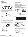
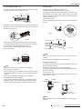
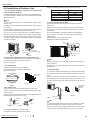
INSTALLATION MANUAL
Model: QS09-VJ115
QS12-VJ115
QS09-VP115
QS12-VP115
(Refrigerant R410A)
Service Manual
Part Ⅱ : Installation and Maintenance
7. Notes for Installation and Maintenance
Safety Precautions:
Important!
Please read the safety precautions carefully before installation and maintenance.
The following contents are very important for installation
and maintenance.
Please follow the instructions below.
●The installation or maintenance must accord with the
instructions.
●Comply with all national electrical codes and local
electrical codes.
●Pay attention to the warnings and cautions in this
manual.
●All installation and maintenance shall be performed by
distributor or qualified person.
●All electric work must be performed by a licensed
technician according to local regulations and the
instructions given in this manual.
●Be caution during installation and maintenance. Prohibit
incorrect operation to prevent electric shock, casualty and
other accidents.
Warnings
Electrical Safety Precautions:
1. Cut off the power supply of air conditioner before
checking and maintenance.
2. The air condition must apply specialized circuit and
prohibit share the same circuit with other appliances.
3. The air conditioner should be installed in suitable
location and ensure the power plug is touchable.
4. Make sure each wiring terminal is connected firmly
during installation and maintenance.
5. Have the unit adequately grounded. The grounding
wire can’t be used for other purposes.
6. Must apply protective accessories such as protective
boards, cable-cross loop and wire clip.
7. The live wire, neutral wire and grounding wire of
power supply must be corresponding to the live wire,
neutral wire and grounding wire of the air conditioner.
8. The power cord and power connection wires can’t be
pressed by hard objects.
9. If power cord or connection wire is broken, it must be
replaced by a qualified person.
22
10. If the power cord or connection wire is not long enough,
please get the specialized power cord or connection wire
from the manufacture or distributor. Prohibit prolong the wire
by yourself.
11. For the air conditioner without plug, an air switch must
be installed in the circuit. The air switch should be all-pole
parting and the contact parting distance should be more than
3mm.
12. Make sure all wires and pipes are connected properly and
the valves are opened before energizing.
13. Check if there is electric leakage on the unit body. If yes,
please eliminate the electric leakage.
14. Replace the fuse with a new one of the same specification
if it is burnt down; don’t replace it with a cooper wire or
conducting wire.
15. If the unit is to be installed in a humid place, the circuit
breaker must be installed.
Installation Safety Precautions:
1. Select the installation location according to the requirement of this manual.(See the requirements in installation
part)
2. Handle unit transportation with care; the unit should not
be carried by only one person if it is more than 44lb.
3. When installing the indoor unit and outdoor unit, a sufficient fixing bolt must be installed; make sure the installation
support is firm.
4. Ware safety belt if the height of working is above 6.6ft.
5. Use equipped components or appointed components during installation.
6. Make sure no foreign objects are left in the unit after finishing installation.
Improper installation may lead to fire hazard, explosion,
electric shock or injury.
Technical Information
Service Manual
Main Tools for Installation and Maintenance
1. Level meter, measuring tape
2. Screw driver
3. Impact drill, drill head, electric drill
4. Electroprobe
5. Universal meter
6. Torque wrench, open-end wrench, inner
hexagon spanner
7. Electronic leakage detector
8. Vacuum pump
9. Pressure meter
10. Pipe pliers, pipe cutter
11. Pipe expander, pipe bender
12. Soldering appliance, refrigerant container
Installation and Maintenance
23
Service Manual
8. Installation
8.1 Installation Dimension Diagram
At least 0.5ft.
Space to the ceiling
Installation dimension diagram
Space to the wall
Space to the wall
At least 0.5ft.
At least 8.2ft.
ft.
10
st
lea
At
ac
At
et
ot
lea
st
e
ac
Sp
24
he
to
o
et
ac
Sp
ll
n
tio
uc
tr
bs
o
the
st
a
t le
A
wa
1ft
At least 1.6ft.
Sp
Space to the obstruction
Sp
ac
et
ot
he
ob
str
uc
tio
Space to the floor
n
At least 0.5ft.
.
1ft
.
the
on
t.
.6f
t6
cti
Drainage pipe
u
str
ob
At
Sp
s
lea
At
ac
et
lea
st
ot
he
1.6
ft.
ob
str
uc
tio
n
Installation and Maintenance
Service Manual
Installation procedures
Start installation
Preparation before installation
Read the requirements
for electric connection
select installation
location
Select indoor unit
installation location
Prepare tools
Select outdoor unit
installation location
Install the support of outdoor unit
(select it according to the actual situation)
Install wall-mounting
frame, drill wall holes
Connect pipes of indoor
unit and drainage pipe
Fix outdoor unit
Connect wires of indoor unit
Install drainage joint of outdoor unit
(only for cooling and heating unit)
Bind up pipes and
hang the indoor unit
Make the bound pipes pass
through the wall hole and then
connect outdoor unit
Connect pipes of outdoor unit
Connect wires of outdoor unit
Neaten the pipes
Vacuum pumping and leakage detection
Check after installation and test operation
Finish installation
Note: this flow is only for reference; please find the more detailed installation steps in this section.
Installation and Maintenance
25
Service Manual
8.2 Installation Parts-checking
No.
1
2
Name
Indoor unit
Outdoor unit
No.
8
9
3
Connection pipe
10
4
Drainage pipe
Wall-mounting
frame
Connecting
cable(power cord)
Wall pipe
11
5
6
7
12
13
Name
Sealing gum
Wrapping tape
Support of outdoor
unit
Fixing screw
Drainage plug(cooling
and heating unit)
Owner’s manual,
remote controller
Note:
1.Please contact the local agent for installation.
2.Don't use unqualified power cord.
8.3 Selection of Installation Location
1. Basic Requirement:
Installing the unit in the following places may cause
malfunction. If it is unavoidable, please consult the local dealer:
(1) The place with strong heat sources, vapors, flammable or
explosive gas, or volatile objects spread in the air.
(2) The place with high-frequency devices (such as welding
machine, medical equipment).
(3) The place near coast area.
(4) The place with oil or fumes in the air. in the air.
(5) The place with sulfureted gas.
(6) Other places with special circumstances.
2. Indoor Unit:
(1) There should be no obstruction near air inlet and air outlet.
(2) Select a location where the condensation water can be
dispersed easily and won't affect other people.
(3) Select a location which is convenient to connect the
outdoor unit and near the power socket.
(4) Select a location which is out of reach for children.
(5) The location should be able to withstand the weight of
indoor unit and won't increase noise and vibration.
(6) The height of indoor unit should be between 8ft. from the
floor in order to provide sufficient space for maintenance.
(7) Don't install the indoor unit right above the electric
appliance.
(8) The appliance shall not be installed in the laundry
3. Outdoor unit:
1.Select a location where the noise and outflow air emitted by
the outdoor unit will not affect neighborhood.
2.The location should be well ventilated and dry, in which the
outdoor unit won't be exposed directly to sunlight or strong
wind.
3.The location should be able to withstand the weight of
outdoor unit.
4.Make sure that the installation follows the requirement of
installation dimension diagram.
5.Select a location which is out of reach for children and far
away from animals or plants.If it is unavoidable, please add
fence for safety purpose.
26
8.4 Requirements Forelectric Connection
1. Safety precaution
(1) Must follow the electric safety regulations when installing
the unit.
(2) According to the local safety regulations, use qualified
power supply circuit and air switch.
(3) Make sure the power supply matches with the requirement
of air conditioner. Unstable power supply or incorrect wiring
may result in electric shock,fire hazard or malfunction. Please
install proper power supply cables before using the air
conditioner.
(4) Properly connect the live wire, neutral wire and grounding
wire of power socket.
(5) Be sure to cut off the power supply before proceeding any
work related to electricity and safety.
(6) Do not put through the power before finishing installation.
(7) For appliances with type Y attachment,the instructions
shall contain the substance of thefollowing.If the supply cord is
damaged,it must be replaced by the manufacturer,its service
agent or similarly qualified persons in order to avoid a hazard.
(8) The temperature of refrigerant circuit will be high, please
keep the interconnection cable away from the copper tube.
2. Grounding requirement:
(1) The air conditioner is first class electric appliance. It must
be properly grounding with specialized grounding device
by a professional. Please make sure it is always grounded
effectively, otherwise it may cause electric shock.
(2) The yellow-green wire in air conditioner is grounding wire,
which can't be used for other purposes.
(3) The grounding resistance should comply with national
electric safety regulations.
(4) The appliance must be positioned so that the plug is
accessible
(5) An all-pole disconnection switch having a contact separation
of at least 3mm in all poles should be connected in fixed wiring.
(6) Including an air switch with suitable capacity, please note
the following table. Air switch should be included magnet
buckle and heating buckle function, it can protect the circuitshort and overload. (Caution: please do not use the fuse only
for protect the circuit)
8.5 Installation of Indoor Unit
1. Choosing Installation Iocation
Recommend the installation location to the client and then
confirm it with the client.
2. Install Wall-mounting Frame
(1) Hang the wall-mounting frame on the wall; adjust it in
horizontal position with the level meter and then point out the
screw fixing holes on the wall.
(2) Drill the screw fixing holes on the wall with impact drill (the
specification of drill head should be the same as the plastic
expansion particle) and then fill the plastic expansion particles
in the holes.
(3) Fix the wall-mounting frame on the wall with tapping screws
(ST4.2X25TA) and then check if the frame is firmly installed by
pulling the frame. If the plastic expansion particle is loose,
please drill another fixing hole nearby.
Installation and Maintenance
Service Manual
3. Install Wall-mounting Frame
(1) Choose the position of piping hole according to the direction
of outlet pipe. The position of piping hole should be a little
lower than the wall-mounted frame.(As show in Fig.1)
Wall
Left
Ф55 mm
Φ2.2
inch
Wall
Mark on the middle of it
Space
to
the
Space
to the
wall
wall
1 5 0 m5ft.
m
above
above
Gradienter
Right
Fig.1
(Rear piping hole)
Space
to the
Space
to
the
wall
wall
5ft.
150m
m
above
above
(Rear piping hole)
Φ2.2mm
inch
Ф55
(2) Open a piping hole with the diameter of Φ55 on the selected
outlet pipe position.In order to drain smoothly, slant the piping
hole on the wall slightly downward to the outdoor side with the
gradient of 5-10°.(As show in Fig.2)
Indoor
5. Connect the Pipe of Indoor Unit
(1) Aim the pipe joint at the corresponding bellmouth.(As show
in Fig.5)
(2) Pretightening the union nut with hand.
(3) Adjust the torque force by referring to the following sheet.
Place the open-end wrench on the pipe joint and place the
torque wrench on the union nut. Tighten the union nut with
torque wrench.(As show in Fig.6)
(4) Wrap the indoor pipe and joint of connection pipe with
insulating pipe, and then wrap it with tape.(As show in Fig.7)
Open-end
wrench
Union nut
Pipe joint
Union nut
Pipe
Fig.5
Φ55 inch
or Φ70
Φ2.2
Insulating pipe
Fig.2
Hex nut diameter(inch)
1/4"
3/8”
1/2”
5/8”
3/4”
(1) Pay attention to dust prevention and take relevant safety
measures when opening the hole.
(2) The plastic expansion particles are not provided and should
be bought locally.
4. Outlet pipe
(1) The pipe can be led out in the direction of right, rear right,
left or rear left.(As show in Fig.3)
(2) When selecting leading out the pipe from left or right, please
cut off the corresponding hole on the bottom case.(As show in
Fig.4)
Tightening torque(N.m)
15~20
30~40
45~55
60~65
70~75
6. Install Drain Hose
(1) Connect the drain hose to the outlet pipe of indoor unit.(As
show in Fig.8)
(2) Bind the joint with tape.(As show in Fig.9)
Outlet pipe
Left
Right
Rear left
Rear right
Fig.8
Outlet
pipe
Drain hose
Drain hose
Tape
Fig.9
Note:
Right
Cut off
the hole
Fig.7
Refer to the following table for wrench moment of force:
Note:
Left
Fig.6
Indoor pipe
Outdoor
5-10°
Fig.3
Pipe
Torque wrench
Fig.4
(1) Add insulating pipe in the indoor drain hose in order to
prevent condensation.
(2) The plastic expansion particles are not provided.
(As show in Fig.10)
Drain hose
Insulating pipe
Installation and Maintenance
Fig.10
27
Service Manual
7. Connect Wire of Indoor Unit
8. Bind up Pipe
(1) Open the panel, remove the screw on the wiring cover and
then take down the cover.(As show in Fig.11)
(1) Bind up the connection pipe, power cord
and drain hose with the band.(As show in Fig.14)
(2) Reserve a certain length of drain hose and power cord
for installation when binding them. When binding to a certain
degree, separate the indoor power and then separate the drain
hose.(As show in Fig.15)
(3) Bind them evenly.
(4) The liquid pipe and gas pipe should be bound separately at
the end.
Panel
Fig.11
Screw
Wiring cover
(2) Make the power connection wire go through the cable-cross
hole at the back of indoor unit and then pull it out from the front
side.(As show in Fig.12)
Indoor unit
Gas
pipe
Fig.14
Cable-cross
hole
Indoor and
outdoor power cord
Liquid
pipe
Band
Drain hose
Power connection
wire
Fig.12
(3) Remove the wire clip; connect the power connection wire
to the wiring terminal; tighten the screw and then fix the power
connection wire with wire clip.(As show in Fig.13)
(4) Put wiring cover back and then tighten the screw.
(5) Close the panel.
N(1) 2
3
Fig.13
Note:
(1) All wires of indoor unit and outdoor unit should be
connected by a professional.
(2) If the length of power connection wire is insufficient, please
contact the supplier for a new one. Avoid extending the wire by
yourself.
(3) For the air conditioner with plug, the plug should be
reachable after finishing installation.
(4) For the air conditioner without plug, an air switch must be
installed in the line. The air switch should be all-pole parting
and the contact parting distance should be more than 3mm.
Connection pipe
Drain hose
Indoor power cord
Band
Fig.15
Note:
(1) The power cord and control wire can't be crossed or
winding.
(2) The drain hose should be bound at the bottom.
9. Hang the Indoor Unit
(1) Put the bound pipes in the wall pipe and then make them
pass through the wall hole.
(2) Hang the indoor unit on the wall-mounting frame.
(3) Stuff the gap between pipes and wall hole with sealing gum.
(4) Fix the wall pipe.
(As show in Fig.16)
(5) Check if the indoor unit is installed firmly and closed to the
wall.(As show in Fig.17)
Indoor
Wall pipe
Outdoor
Sealing gum
Fig.17
Upper hook
Fig.16
Lower hook of
wall-mounting frame
Note:
Do not bend the drain hose too excessively in order to prevent
blocking.
28
Installation and Maintenance
Service Manual
8.6 Installation of Outdoor Unit
Refer to the following table for wrench moment of force:
1. Fix the support of outdoor unit(select it according to the
actual installation situation)
Hex nut diameter(inch)
1/4"
3/8”
1/2”
5/8”
3/4”
(1) Select installation location according to the house structure.
(2) Fix the support of outdoor unit on the selected location with
expansion screws.
Note:
(1) Take sufficient protective measures when installing the
outdoor unit.
(2) Make sure the support can withstand at least four times the
unit weight.
(3) The outdoor unit should be installed at least 3cm above the
floor in order to install drain joint.(As show in Fig.18)
(4) For the unit with cooling capacity of 2300W~5000W, 6
expansion screws are needed; for the unit with cooling capacity
of 6000W~8000W, 8 expansion screws are needed; for the
unit with cooling capacity of 10000W~16000W, 10 expansion
screws are needed.
Tightening torque(N.m)
15~20
30~40
45~55
60~65
70~75
5. Connect Outdoor Electric Wire
(1)Remove the cable-crossing board 2 of right side plate for
outdoor unit.
(2)Remove the wire clamps, pass the power connection cord
and power cord through the cable-crossing board 1 to connect
the terminal.
The wiring distribution must match with the electric diagram.
(3)Fix the power connection cord and power cord with wire
clamps tightly.
(4)Check whether the wiring is fixed well.
(5)Install the cable-crossing board 2.
cable-crossing board 2
N
Drain vent
At least 3cm above the floor
3. Fix Outdoor Unit
(1) Place the outdoor unit on the support.
(2) Fix the foot holes of outdoor unit with bolts.
(As show in Fig.20)
Foot holes
cable-crossing
board 2
Foot holes
Fig.21
Fig.20
4. Fix Outdoor Unit
(1) Remove the screw on the cable-crossing board 2 of
outdoor unit and then remove the cable-crossing board 2.(As
show in Fig.21)
(2) Remove the screw cap of valve and aim the pipe joint at the
bellmouth of pipe.(As show in Fig.22)
Liquid
valve
N
3
Fig.23
Note:
(1) After tightening the screw, pull the power cord slightly to
check if it is firm.
(2) Never cut the power connection wire to prolong or shorten
the distance.
6. Neaten the Pipes
(1) The pipes should be placed along the wall, bent reasonably
and hidden possibly. Min. semidiameter of bending the pipe is
10cm.
(2) If the outdoor unit is higher than the wall hole, you must set
a U-shaped curve in the pipe before pipe goes into the room,
in order to prevent rain from getting into the room.(As show in
Fig.24)
The drain hos
can't raise
upwards
Wall
U-shaped curve
Fig.25
Drain hose
Note:
Union nut
Fig.22
(3) Pretightening the union nut with hand.
(4) Tighten the union nut with torque wrench .
Installation and Maintenance
L
Indoor unit connection
Fig.24
Pipe joint
gas pipe
gas valve
POWER
cable-crossing board 1
Fig.18
Fig.19
2. Install Drain Joint(Only for cooling and heating unit)
(1) Connect the outdoor drain joint into the hole on the chassis.
(2) Connect the drain hose into the drain vent.
(As show in Fig.19)
Liquid pipe
L
2
Chassis
Outdoor drain joint
Drain hose
2 3
(1) The through-wall height of drain hose shouldn't be higher
than the outlet pipe hole of indoor unit.(As show in Fig.25)
(2) Slant the drain hose slightly downwards. The drain hose
can't be curved, raised and fluctuant, etc.(As show in Fig.26)
29
Service Manual
(3) The water outlet can't be placed in water in order to drain
smoothly.(As show in Fig.27)
8.8 Check after Installation and Test
operation
1. Check after Installation
Check according to the following requirement after finishing
installation.
The drain hose can't be fluctuant
NO.
The drain hose
can't be fluctuant
The water
outlet can't be
fluctuant
1
The water outlet
can't be placed
in water
2
Fig.27
Fig.26
4
8.7 Vacuum Pumping and Leak Detection
1. Use Vacuum Pump
(1) Remove the valve caps on the liquid valve and gas valve
and the nut of refrigerant charging vent.
(2) Connect the charging hose of piezometer to the refrigerant
charging vent of gas valve and then connect the other charging
hose to the vacuum pump.
(3) Open the piezometer completely and operate for 10-15min
to check if the pressure of piezometer remains in -0.1MPa.
(4) Close the vacuum pump and maintain this status for 1-2min
to check if the pressure of piezometer remains in -0.1MPa. If
the pressure decreases, there may be leakage.
(5) Remove the piezometer, open the valve core of liquid valve
and gas valve completely with inner hexagon spanner.
(6) Tighten the screw caps of valves and refrigerant charging
vent.
(As show in Fig.28)
Liquid valve
Piezometer
Lo
Hi
Gas valve
Refrigerant charging
vent
Valve cap
Nut of refrigerant
Charging vent
Vacuum pump
Inner hexagon
spanner
Fig.28
3
Close
Open
Items to be checked
Has the unit been
installed firmly?
Have you done the
refrigerant leakage test?
Is heat insulation of
pipeline sufficient?
Is water drained well?
Is the voltage of power
supply according to the
5
voltage marked on the
nameplate?
Is electric wiring and
6 pipeline installed
correctly?
Is the unit grounded
7
securely?
Does the power cord
8
follow the specification?
Is there any obstruction
9
in air inlet and air outlet?
The dust and
sundries caused
10
during installation are
removed?
The gas valve and liquid
11 valve of connection pipe
are open completely?
Possible malfunction
The unit may drop, shake or
emit noise.
It may cause insufficient cooling
(heating) capacity.
It may cause condensation and
water dripping.
It may cause condensation and
water dripping.
It may cause malfunction or
damage the parts.
It may cause malfunction or
damage the parts.
It may cause electric leakage.
It may cause malfunction or
damage the parts.
It may cause insufficient cooling
(heating).
It may cause malfunction or
damaging the parts.
It may cause insufficient cooling
(heating) capacity.
2. Test operation
(1) Preparation of test operation
● The client approves the air conditioner installation.
● Specify the important notes for air conditioner to the client.
(2) Method of test operation
● Put through the power, press ON/OFF button on the remote
controller to start operation.
● Press MODE button to select AUTO, COOL, DRY, FAN and
HEAT to check whether the operation is normal or not.
● If the ambient temperature is lower than 16℃ , the air
conditioner can’t start cooling.
2. Leakage detection
(1) With leakage detector:
Check if there is leakage with leakage detector.
(2) With soap water:
If leakage detector is not available, please use soap water for
leakage detection. Apply soap water at the suspected position
and keep the soap water for more than 3min. If there are air
bubbles coming out of this position, there's a leakage.
30
Installation and Maintenance