1
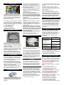
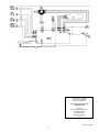
SERVICE
SUMMARY
WL37T26C
WL37T26D
This information is intended for use by individuals possessing adequate experience in servicing electrical, electronic and mechanical appliances. Any attempt to
repair a major appliance may result in personal injury and property damage. The manufacturer or seller cannot be responsible for the interpretation of this
information, nor can it assume any liability in connection with its use.
Cette information est destinée aux personnes possédant l’expérience requise pour réparer des appareils électriques, électroniques et mécaniques. Toute tentative
de réparation d’un gros appareil comporte un risque de blessures à personnes et de dommages matériels. Le fabricant et le revendeur ne peuvent en aucun cas
être chargés de l’interprétation de cette information, ni assumer aucune responsabilité en rapport avec son utilisation.
IMPORTANT SAFETY INFORMATION
CAUTION: This machine must be electrically grounded. It can be grounded through the grounding lead in the 3-prong power cord, if plugged
into a properly grounded appliance outlet or through a separate No. 13 or larger wire from the cabinet to an established ground. In all cases
the grounding method must comply with any local electrical code requirements. Certain internal parts are intentionally NOT GROUNDED and
may present a risk of electrical shock only during servicing. Service personnel do not contact the Water Valve Brackets while the appliance is
energised. To reduce the risk of shock, disconnect the power supply cord before servicing.
CAUTION: ALL TERMINALS AND INTERNAL PARTS SHOULD BE TREATED AS LIVE.
IMPORTANT – RE-CONNECT ALL GROUNDING DEVICES.
If grounding wires, screws, straps, clips, nuts or washers used to complete a path to ground are removed for service, they must be returned to
their original position and properly fastened.
IMPORTANTES CONSIGNES DE SÉCURITÉ
ATTENTION : Cette machine doit être mise à la terre. Elle peut l’être par le biais du conducteur de terre du cordon d’alimentation à prise
de terre mâle, s’il est branché sur un point de réseau électrique correctement mis à la terre, ou par le biais d’un fil électrique épais séparé
de l’appareil à la terre. Certaines pièces internes ne sont pas MISES A LA TERRE selon les normes internationales et peuvent présenter
un risque d’électrocution durant l’entretien. Le personnel d’entretien ne doit pas toucher les supports d’électrovanne. Pour réduire le risque
d’électrocution, le cordon d’alimentation doit être débranché avant tout entretien de l’appareil.
ATTENTION : TOUTES COSSES DE CÂBLES ET PIÈCES INTERNES SONT À TRAITER COMME ÉTANT SOUS TENSION
IMPORTANT – REBRANCHER TOUS LES DISPOSITIFS AVEC MISE À LA TERRE
Si les conducteurs de terre, vis, barrettes, clips, écrous ou rondelles utilisés pour acheminer le circuit à la terre sont ôtés lors de l’entretien, ils
doivent être solidement remis à leur place d’origine.
AQUASMART - A brief Overview
STATOR
Note: The rotor is not interchangeable with
any previous phase or series of machine.
ELECTRONICS
The Motor Control Module contains the
circuits needed to control the water valves,
pump, water level and rotation of the motor.
The Pressure Sensor, used to detect the
water level, is part of the Motor Control
Module and cannot be removed. The Display Module receives the inputs from the
front panel (i.e. User settings) and sends
the appropriate command to the Motor
Control Module.
NOTE: There are no field serviceable
parts within the Motor Control Module or
Display Module.
The rotor has 16 blocks of magnets, which
each contain 3 individual magnets.
ROTOR POSITION SENSOR R.P.S.
The resistance between any two phases
should be 32Ω
Note: The stator is not interchangeable with
any previous phase or series of machine.
ROTOR
MOTOR
The motor is a 3-phase DC brushless motor which has 36 poles. The Motor Control
Module controls rotation of the motor.
-1-
The rotor position sensor (RPS) is a printed
circuit board that contains three Hall Sensors,
which detect the magnetic field of the individual magnets in the rotor. The RPS provides
this information to the Motor Control Module,
which it uses to determine the position of the
rotor. The printed circuit board sits in a plastic
housing encapsulated by resin to protect the
board. The only exposed area of the board is
the connector for the main harness.
WATER VALVES
The water valve assembly incorporates four
valves that are joined by a common valve
body. The two main inlet coils control the flow
of water into the valve body assembly which
then in turn supply water into the machine
through the inlet nozzle.
Two additional coils are used which control the
valves for the bleach and detergent dispensing
which control the flow of water to the detergent
and bleach dispensing system via hoses which
run underneath the top deck.
1. Hot coil (White Clip)
2. Cold coil (White Clip)
3. Bleach coil (Yellow Clip)
4. Detergent coil (Purple Clip)
DISPENSING SYSTEM
a) Lift the lid; remove the low profile agitator
cap by using an appropriate flat bladed
screwdriver in one side of the slots. Lever the
cap upwards until it disengages. The cap can
then be removed by hand.
b) Remove the bolt by turning anti-clockwise
using a 13mm open-ended wrench or an
adjustable wrench. We do not advise using a
socket for this task.
c) Remove the low profile agitator.
Note: If the low profile agitator does not
lift off easily, hold the top balance ring of
the inner bowl, then jerk the bowl upwards.
This action will push the agitator upwards.
Reassembly:
a) Refit in reverse manner, ensuring that the
low profile agitator is pushed down as far as
it can go.
b) Insert the thread of the bold into the shaft
and tighten as much as possible by hand.
c)Tighten an additional 1/2 turn using an open
ended or adjustable spanner, or tighten to a
torque of 6Nm.
Note: Over-tightening will cause excessive
damage to the castellations on the agitator,
and may cause the head of the bolt to shear
off. Failure to tighten the bolt correctly will
cause the agitator to lift off the spline on
the shaft during wash.
d) Fit the cap to the top of the bolt. Using your
hand hit firmly on top of the cap until the
clips on the cap engage to the bolt.
DRAIN PUMP (Smart Pump)
1. Ensure the machine is level, stable on the floor and that the rubber pads are inserted into
the feet.
2. Check the weight of the inner basket
(23.10lb +/- 9.7oz / 10.48kg +/- 275g). This
is to ensure the Ballast rings have the correct
amount of water.
3.Check rotor position sensor.
Note: If the OOB problem persists after
checking the above, we would then recommend replacing both the suspension rods
and the rotor. It is highly unlikely that the
Motor Control Module will be the cause.
LINT REMOVAL SYSTEM
As a result of the agitator action, lint and wash
water is drawn through holes in the agitator
and down to the base, where they are directed
into the cavity between the basket and tub.
The holes in the basket allow the wash water
to flow back into the basket but prevent the
lint from following. Lint is carried out with the
waste water.
SETTING MENU (LCD Model Only)
After using your AQUASMART™ washer you
may wish to fine-tune some of the options
to suit your individual needs. Any options
changed in this menu is a permanent change,
unless ‘Reset Defaults’ is selected. In the
Settings Menu the following settings can
be adjusted.
Temperature Adjust
Two hoses run underneath the top deck and
connect to either the detergent dispenser or
the bleach dispenser. The detergent dispenser
hose has cream elbows. The bleach dispenser
hose has grey elbows.
Moulded in the top deck at the valve end are
identification letters (‘D’ for Detergent and ‘B’
for Bleach). At the dispenser end are moulded
the words ‘Detergent’ and ‘Bleach’.
Note: It is important that the hoses are
retained in the clips around the perimeter
of the opening of the top deck correctly.
FLOATING BASKET
During spin, the agitator and the basket have
to be coupled together and turn as a single
unit. In agitate, the agitator and basket have to
be free to rotate independently.
At the base of the basket is a flotation chamber. As the water level rises the basket will
float. This action disconnects a clutch between
the agitator and basket. The agitator and basket can now move independently.
When the water is pumped out, the basket
sinks down and re-engages, allowing the agitator and basket to turn as one unit.
LOW PROFILE AGITATOR
Note: Removal of low profile agitator is not
intended to be done by the user as regular
maintenance in this area should not be
required.
Aqua Plus (Adds
extra water to the
AquaRinse in the
HE cycle
SmartPump has the capability of pumping to a
much higher head (8ft / 2.5 metres).
The pump housing is attached to the base of
the tub. The pump can be accessed from the
top, if the agitator and basket are removed, or
from underneath the machine. Care must be
taken to isolate the machine from the mains
power before servicing the pump and it is important that the harness connector cover has
been replaced after reassembly.
LIDLOCK
This machine has a lidlock that will lock the lid
closed when the machine is operating. The
lid is closed for the entire cycle. If the user
attempts to operate the machine with the lid
in the open position the machine will stop and
sound a warning tune. See user warnings
OUT OF BALANCE DETECTION
AquaSmart has an electronic sensing system
known as ‘Bump Detect’. ‘Bump Detect’ is
software written into the Motor Control Module,
which looks at specific feedback from the Rotor Position Sensor. No fault codes are associated with ‘Bump Detect’, and there are no hard
and fast tests that can be carried out.
If a machine continually goes into an out of
balance condition then the following needs to
be checked in the order given.
-2-
Key Lock Mode
Hints
Service Contacts
Balance Recovery
Troubleshooting
Alarm Beeps
Reset Defaults
Screen Brightness
Replay Intro
To access the Settings Menu:
1 Turn your AQUASMART™ washer on.
2 Scroll, to the right, through the wash cycles
until you reach the Settings Menu.
3 Press SELECT to enter the menu.
USER FAULTS (LCD Model Only)
Incorrect installation or operation can cause
user faults. The washer can detect these and
alert the operator by a musical series of beeps
every 5 seconds and displaying a warning
on the LCD screen. These warnings are also
listed in the Use & Care Manual.
“My Load is out of balance”
Refer to Out of Balance Detection as detailed
above.
“I am not getting any WATER”
1. The faucets haven’t been turned on.
2. Inlet hose screens may be blocked.
3. The hoses may be kinked.
4. The drain hose is too low or the drain hose
is pushed into the standpipe too far and the
water is siphoning out of the machine.
5. The flow rate of the water is too slow.
“I am not getting any HOT WATER”
Hot water supply is not hot enough to maintain
the temperature you have selected.
1. Select a lower wash temperature.
2. Inlet hose screens may be blocked.
3. There may be a kink in the hose.
4. Hot faucet has not been turned on.
5. Inlet hoses connected to the wrong faucets.
I am not getting any COLD WATER”
1. Cold faucet hasn’t been turned on.
2. Inlet hose screens may be blocked.
3. There may be a kink in the hose.
4. Inlet hoses connected to the wrong faucets.
5. Cold water exceeds recommended limits.
6. The flow rate of water may be too slow.
“I am OVERLOADED”
The machine is overloaded and cannot agitate.
1. Begin removing items until the remaining
ones can move freely.
2. Check the machine is not syphoning
“I have TOO MANY SUDS”
Your machine has a suds build-up. Too much
detergent may have been used for the amount
of soil in the load.
1. Ensure that you are using a HE Low Sudsing,
Matic or Front Loader type detergent.
2. Wait for suds to dissolve (about 20 minutes).
Rinse clothing using the RINSE and
SPIN cycle.
“I can’t LOCK THE LID”
Check that the lid is closed.
Press START PAUSE.
IF FAILURE OCCURS (LCD Model Only)
Most failures are diagnosed by the Diagnostic
System. If a fault is detected, the operation of
the machine will stop and a fault code will appear on the LCD display screen. A continuous
beeping sound will also occur. If this happens:
1. Remove the plug from the wall outlet for at
least one-minute.
2. Plug in and start the machine. If the
condition recurs, use the Diagnostic Mode to
determine the cause.
DIAGNOSTIC MODE (LCD Model Only)
The washers are fitted with a diagnostic system
designed to help test the machine and obtain
information that will assist in locating a fault.
The Diagnostic mode also incorporates tests
for both the drain pump and the water valves.
In this screen will be displayed a fault code for
the last fault that has occurred and will show
how many cycles ago and in what part of the
cycle it occurred. The fault code number can
now be checked in the detailed fault codes,
to ascertain what repairs may be necessary.
Refer to detailed fault descriptions
section of this document.
Machine Status
In the top half of the screen it displays the
following information.
Size is the size of machine, (650mm = Large)
HVDC is for on line testing in the factory.
WL displays the water level in mm.
T is the actual temp of the inlet chamber water.
Target temp is the temperature selected.
In the lower half of the screen it displays the
status
of the following components.
• Hot Valve (HOT)
• Cold Valve (COLD)
• Detergent Valve (DET)
• Softener and Bleach (FAB)
• SmartPump (PUMP)
Component Testing
In this screen the components that are displayed can be tested. To test a component,
firstly highlight the component by using the
left and right arrows. To activate a component
press the select button. To deactivate the
component depress the select
button again.
Note: SmartPump can be tested in both the
drain and recirculation modes. After
highlighting Pump, the first press of the Select button activates the pump in the drain
direction, the second press activates the
pump in the recirculation direction, a final
press turns the pump off.
Control Screen
Use the left and right arrows to highlight the
screen you wish to view, then press the
SELECT button to enter that screen. The
screens are explained below.
Service Screen
Upon entering the service screen one of the
following screens will appear
• Warning Status / Fault Status
• Machine Status
To scroll between the screens use the left and
right arrows.
Warning Status / Fault Status
Warning Status
In this screen will be displayed the last USER
WARNING FAULT that occurred and will show
how many cycles ago and in what part of the
cycle it occurred.
If failure occurs (LED model only)
Most failures are diagnosed by the diagnostic
system. If a fault is detected, the operation
of the machine will stop and a fault code will
appear in the cycle buttons on the top row. A
continuous beeping sound will also occur. If
this happens:
1.Remove the plug from the wall outlet for at
least one-minute.
2.Plug in and start the machine. If the
condition recurs, use the diagnostic mode to
determine the cause.
DIAGNOSTIC MODE (LED Model only)
This washer has a diagnostic system to help
diagnose faults. The diagnostic mode also
tests the drain pump and water valves.
To select the Diagnostic Mode
1.Turn Power on at the wall, and off at the
Console.
2.Press and hold the HIGH EFFICIENCY
button, then press the POWER button. You will hear two beeps.
3.Press the SPIN button three times, until both
the Slow and Hold lights are on. Now you can read the last fault.
4. Fault codes can be found in
DETAILED FAULT DESCRIPTION
For Example:
128
64
32
16
8
4
2
1
This is fault Code 9.- Size setting.
Press & Hold for 2 seconds
To Select DIAGNOSTIC MODE
1. Turn the power on at the power point and off
at the console.
2. Press and hold the HI-EFFICIENCY button
and then press the SELECT button, keep the
buttons pressed for at least 2 seconds, after
which time two beeps will sound and the
screen below will appear.
switch the machine off at the wall or disconnect from the mains supply.
For more information refer to the service
manual.
Hot Bowl
If the machine has been filled with the hot water valve utilised (ie. warm or hot fill) and has
not had a cold rinse, the electronics will not
allow the machine to spin up to its full speed of
1000 RPM. It will only allow the spin speed to
reach 700 RPM.
Restart
The machine leaves the factory with the
RESTART set to the ON position, which is
indicated in the screen by the word RESTART
highlighted. To turn the RESTART feature
OFF, push the Left arrow. This will remove the
highlight from the word RESTART. When the
machine is being serviced, it is more convenient to turn the RESTART feature OFF. This
will allow any fault in the system to show up
immediately.
Recycle
At the end of servicing, the machine may require an extended test where the machine can
be left to complete a number of wash cycles.
By turning on the RECYCLE feature the machine will continuously repeat the wash cycle
until the RECYCLE feature is turned off.
NOTE – The Restart & Recycle feature are
designed as a service aid only and should be
OFF in the customer’s home, and ON for
restart. To return to normal operation, and to
return the recycle feature to the factory setting,
-3-
If this appears you need to set the size of the
LED AquaSmart:
1.Press and Hold the SPIN button, then press
the POWER button. You will hear three beeps.
2. Press the BLEACH button once to size the
machine.
3.Press the POWER button.
Component testing (LED Model only)
To select the Component Test Mode.
1.Press and Hold theHIGH EFFICIENCY
button, then press the POWER button. You will
hear two beeps.
2.Press the SPIN button until all the spins
lights are on.
To Check:
Hot Water Valve
Push REGULAR button
Cold Water Valve
Push HEAVY button
Detergent Valve
Push DELICATE then REGULAR button
Bleach Valve
Push SHEETS then REGULAR button
Drain Pump
Push BULKY button
Pump Recirc
Push EASY IRON button
RESTART
This feature makes the machine “re-try”
when something goes wrong.
The AquaSmart leaves the factory with the
RESTART turned ON. When servicing the
AquaSmart it is more convenient to turn this
OFF. It will allow any fault to show up
immediatly.
To turn RESTART OFF
In COMPONENT TEST MODE,
push BLEACH button
RECYCLE
After servicing, you may want to put the
machine into RECYCLE mode to complete a
number of cycles.
To turn RECYCLE ON
In COMPONENT TEST MODE,
push SOAK button
To turn RECYCLE OFF
In COMPONENT TEST MODE,
push SOAK button
DETAILED FAULT DESCRIPTION
Some common fault descriptions are shown
in the following columns, for full detailed fault
code information refer to the Service Manual.
See Detailed Fault Codes for servicing tips.
Note: If a fault code is displayed that is not
listed, refer to the Service Manual.
Valve Faults
For fault codes 26, 27, 49, & 50 the Motor
Control Module has measured a voltage from
the valve diagnostic circuit that indicates the
cold valve or both the cold and hot valve or
dispensing valves are faulty. The most likely
cause is that the valve harness has not been
connected correctly or the valve(s) is open
circuit.
• Check the valve harnesses are correctly
fastened to the valves and the motor control
module or the pins are not bent backwards.
• Measure the resistance of the cold and hot
valve coils.
• Replace the Motor Controller module.
Pressure Tube Faults
Fault codes 38 & 39 relates to a fault in the
pressure tube area of the machine.
The probable cause of this fault is that the
pressure tube has become blocked, crushed
cut or has fallen off. If no faults are found with
the pressure tube, replace the Motor Control
Module.
Temperature Sensor (Thermistor) Faults
Fault codes 10, 41 & 237 relate to the temperature sensor (thermistor).
• Check the connection from the thermistor to
the Motor Control Module.
• Check the resistance of the thermistor, it
should read 12.5k ohms @ 68oF (20oC)
Pressure (Sensor) Transducer Faults
Fault codes 68, 69, 70, and 72 relate to faults
with the pressure transducer, which is incorporated in to the Motor Control Module. For any
of these faults the Motor Control Module will
need to be replaced.
Motor Control Module Faults
Fault codes 1, 3, 57, 60, 104, 106, 107, 108,
110, 111, 112, 113, 220, 230, 232, 233, 236,
241, 252 relate to faults with the Motor Control
Module and it will need to be replaced.
Display Module Faults Fault codes 45, 46,
relate to the Display Module and it will need to
be replaced. Lid Lock Faults
Fault codes 234, 235, 238, & 239 relate to
faults with the Lid Lock circuitry.
• Check the connection of the Lid Lock to
harness to the Motor Control Modul
• Test for continuity through the harness to the
Lid Lock. The reading should be 63P +/- 10%
@ 68oF / 20oC. Replace the Lid Lock and
Harness if reading is out of this range.
• Replace the Motor Control Module.
Basket (Bowl) Faults
Fault codes 40, 56, & 160 relate to faults with
the basket or clutch mechanism of the basket.
Test the machine with no clothes in it, if the
faults persists check the following.
• Check the machine is not siphoning.
• Check that there are no clothes or foreign
objects preventing the clutch re-engaging, and
that there aren’t any defects with the clutch
mechanism.
• Check that the pressure tube has not come off
and that it is not kinked.
• Replace the Rotor Position Sensor.
• Replace the Motor Control Module.
Rotor Position Sensor (RPS) Faults
Fault code 130 & 240 relate to faults to do
with the RPS, wiring and Motor Control Module
circuitry.
• Check for corrosion on the connector of
the RPS.
• Test the RPS with an RPS tester.
• Replace the Motor Control Module.
Note for Fault code 240, it normally indicates a problem with the wiring harness.
Motor Faults
Fault codes 136 is a motor stall fault. Possible
causes are seized bearings, fault motor harness, faulty or jammed motor, or a faulty RPS
or Motor Control Module. Check the following.
• Check that the inner basket is free to turn and that it is not jammed.
• Check that the RPS has no signs of corrosion
or water damage.
• Check the resistance of the motor windings.
Normal resistance should be 32 ohms across
any two phases.
•Replace the Motor Control Module.
Pump Faults
Fault codes 245, 247, 248, 249& 250
relates to the pump and the pumping system,
including hoses.
• Check that the drain hose is not kinked, or that
the machine is siphoning.
•Measure the resistances of the Pump windings. The resistance should be approximately
16.2 ohms across any two phases.
• Check that that pump head height does not
exceed 8ft (2.4 metres).
• Remove the inner basket; check that the
hood and cap is fitted correctly, and that the
cap is fitted tightly.
• Check that there is no lint streaming from the
pump hood that may be blocking the pump
cap inlet.
• Remove the pump hood and cap, check for
lint, grit, and debris.
• Check for free movement of the impellor, and
that the impeller hasn’t come off the rotor.
• Check for free movement of the flapper.
• Check for lint and foreign object in the ports
of the pump housing.
• Replace the Motor Control Module.
Product Size Fault Code 9
To set the size of the LED AquaSmart
1. Press and hold the SPIN button, then press
the POWER button. You will hear three beeps.
2. Press the BLEACH button once to size the
machine.
3. Press POWER button.
DISASSEMBLY
Note: The disassembly instructions below are
summarised from the service manual, which
we recommend be used if at all possible.
1. Make sure power and water are
disconnected.
NOTE: There is still power to the components when the POWER button in the
“OFF” state. Always unplug the power
cord before commencing service work or
disassembly.
2. To remove the lid, open it to the up right
position and lift it clear.
3. Remove 2 screws from the rear of the console. The console can be removed to gain
access to the Motor Control Module, Display
Module and wiring.
NOTE: Modules removed from the machine
for return must be protected from electrostatic damage while in transit by using the
special package in which the spare parts
were received.
Removing Top Deck
4.Disconnect Display Module and remove
the console. Disconnect all harnesses to the
Motor Control Module. Remove the pressure
tube. Remove the water valves, then slide the
power cord out from the top deck. Remove the
ground wire.
Note: When replacing a Motor Control Module ensure that the pressure tube is clear
of any water droplets before operating the
machine on a fill cycle. If the basket is full
of water drain the water then blow down
the tube.
5. Remove two rubber buffers and screws from
the front of the top deck.
Removing the Basket
6. Remove the four straps attached to the neck
ring by unclipping each end of the straps from
the neck ring. Unclip the neck ring from the top
of the tub.
7. Remove the agitator as described on
page 2.
8. The basket may now be lifted clear. If the
basket is not easy to lift clear, then remove the
three-spline retaining screws and remove the
driven spline off the shaft and lift out.
Note: Specifications are subject to change
without notice
-4-
BLEACH
DISPENSING VALVE
If further help is needed
concerning this appliance
in USA or Canada call:
TOLL FREE 1.888.9 FNP.USA
(1.888.936.7872)
Or write to:
Fisher & Paykel Appliances Inc
5900 Skylab Road
Huntington beach
California, CA92647
USA
Part No: 421109B
-5-