1
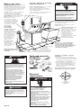
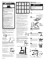
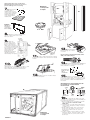
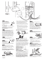
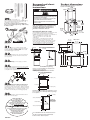
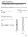
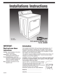
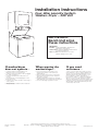
Installation Instructions
Four-Wire Laundry System
Washer•Dryer – 240 Volt
IMPORTANT:
Read and save
these instructions.
IMPORTANT:
Installer: Leave Installation Instructions
with the homeowner.
Homeowner: Keep Installation Instructions
for future reference.
Save Installation Instructions for local
electrical inspector’s use.
Part No. 3405982
If washer/dryer
does not operate...
When moving the
washer/dryer...
If you need
assistance...
• Check that the circuit breaker is not
tripped or the house fuse blown.
• Check that power supply cord is plugged
into wall receptacle.
• Check that washer lid or dryer door is
closed.
• Check that the round shipping piece has
been removed.
• Check that controls are set in a running or
“ON” position.
• Check that dryer “START” button has been
firmly pushed.
• Disconnect the power supply cord.
Tape power supply cord securely to
washer/dryer.
• Tape the dryer drum to the front panel.
Tape the lint screen in place. Tape the
dryer door closed.
• Wedge a blanket between the tub ring
and cabinet top to restrict tub movement.
• Turn front leveling legs all the way in.
Check your Use and Care Guide for a tollfree number to call, or call the dealer from
whom you purchased this appliance. The
dealer is listed in the Yellow Pages of your
phone directory under ”Appliances —
Household — Major — Service and Repair.”
When you call, you will need the washer/
dryer model number and serial number. Both
numbers can be found on the model/serial
rating plate located behind the dryer door
on the dryer door wall.
Part No. 3405982
©1996
Inglis Limited, 1901 Minnesota Court, Mississauga, Ontario L5N 3A7
Washers • Dryers • Refrigerators • Dishwashers • Waste Compactors • Microwave Ovens
BRANCHES ACROSS CANADA
Printed in U.S.A.
Before you start...
Check location where washer/dryer will be
installed. Proper installation is your
responsibility. The washer/dryer must not be
installed or stored in an area where it will be
exposed to water and/or weather. Make
sure you have everything necessary for
correct installation.
Location should be large enough to fully
open dryer door 90°. (See Panel E for
“Recessed and closet installation
instructions” and “Product dimensions.”)
Important : Observe all governing
codes and ordinances.
Check code requirements. Some codes limit
or do not permit the installation of
washer/dryer in garages, closets, mobile
homes and sleeping quarters. Contact your
local building inspector.
Grounded electrical outlet within (1.5m) 5 ft
of the center rear of cabinet is required. See
“Electrical requirements,” Panel A.
Check utilities: Proper electrical supply
must be available. See “Electrical
requirements”, Panel A.
Dryer may be exhausted
from rear or left or right side.
Exhausting through the side
requires Side Exhaust Kit Part
No. 279823. See “Exhaust
requirements,” Panel B.
Water heater: Set to deliver 60°C (140°F)
water to the washer.
Laundry tub drain system needs
a 75.7 litres (16.7 Imperial
gallons) laundry tub. Top of tub
must be at least 71.1 cm (28 in)
high and no higher than 121.9
cm (48 in) from floor.
If a longer drain hose is
needed, Drain Hose Part
No. 388423, and Hose
Connection Kit Part No. 285442,
are available from your
authorized parts distributor.
Drain hose
may also be
installed to a
laundry tub
or floor drain
system.
See Panel D.
Floor drain system
requires a siphon
break, Part No.
285320, available
from your authorized
parts distributor.
Level floor: Maximum
slope under
washer/dryer,
2.5 cm (1 in).
SEE RECESSED AND CLOSET
INSTALLATION INSTRUCTIONS
ON PANEL E .
!! WARNING
Tools and materials
needed for
installation:
Phillips
screwdriver
pliers
Fire Hazard
Do Not use or store gasoline, paint,
thinners and other flammable materials
near washer/dryer. Fumes from such
materials could result in fire or explosion.
Never install washer/dryer up against
draperies or curtains or on carpet. To do
so may result in a fire.
Keep any and all items from falling or
collecting behind the washer/dryer.
Failure to do so may result in a fire.
Replace all access panels before
operating washer/dryer.
Do Not store or operate washer/dryer
below 0°C (32°F) (some water may
remain in washer). Proper operation of
dryer cycles requires temperatures above
7°C (45°F). See Use & Care Guide for
“Winterizing” information.
Support: Floor must be sturdy enough
to support washer/dryer weight with
water and clothes of 170 kg (375 lb).
utility knife
For your safety, the information in this
manual must be followed to minimize the
risk of fire or explosion or to prevent
property damage, personal injury or loss
of life.
Electric Shock Hazard
It is the customer’s responsibility:
To contact a qualified electrical installer.
To assure that the electrical installation is
adequate and in conformance with the
Canadian Electrical Codes, and all local
codes and ordinances.
Failure to follow these instructions can
result in death or electrical shock.
Hot and cold water faucets must be within
1.2 meters (4 feet) of the back of the
washer/dryer and provide water pressure of
34 to 690 kPa (5-100 psi).
10.2 cm (4 in)
metal exhaust
duct is required.
Standpipe drain system
needs a 5 cm (2 in)
diameter standpipe
with a minimum carryaway capacity of
64.4 litres (14.2 Imperial
gallons) per minute.
Top of standpipe must
be at least 71.1 cm
(28 in) high and no
higher than 121.9 cm
(48 in) from floor.
!! WARNING
duct
tape
safety glasses
level
gloves
1/4" socket wrench
or nut driver
slip-joint
pliers that
open
to 3.8 cm
(1-1/2")
minimum
OBSERVE ALL GOVERNING CODES AND
ORDINANCES
1. A four-wire, single-phase, 120/240-volt,
60-Hz, AC only electrical supply is required
on a separate 30-ampere circuit, fused on
both sides of the line. (Time-delay fuse or
circuit breaker is recommended.)
2. This washer/dryer is equipped with a fourwire, 30-amp rated flexible-type power
supply cord. It must be plugged into a
mating 30-amp receptacle (NEMA-type
14-30R). See Figure 1.
Use 30-amp receptacle where local codes
permit flexible-type supply cord (pigtail).
G
Electrical
requirements
!! WARNING
Failure to follow these instructions may
result in a fire.
Y
X
W
14-30R
4-wire receptacle
Figure 1
!! WARNING
Electrical Shock Hazard
Injury Hazard
Electrical ground is required.
More than one person is required to lift,
tilt, or move this washer/dryer because of
its weight and size.
Do Not ground to a gas pipe.
Failure to follow these instructions may
result in injury.
Improper connection of the equipmentgrounding conductor can result in a risk of
electrical shock.
Check with a qualified electrician if you are
not sure this washer/dryer is properly
grounded.
Do Not change the power supply cord plug.
If it will not fit the outlet, have a proper
outlet installed by a qualified electrician.
Do Not have a fuse in the neutral or
grounding circuit.
Do Not use an extension cord with this
washer/dryer.
Panel A
Failure to follow these instructions could
result in death or electrical shock.
Exhaust requirements
!! WARNING
0
1
Fire Hazard
Do Not use non-metal, flexible duct.
Do Not use metal duct smaller than
10.2 cm (4 in) in diameter.
Do Not use exhaust hoods with magnetic
latches.
Check that exhaust system is not longer
than specified. Exhaust systems longer
than specified will:
— Accumulate lint.
— Shorten the life of the product.
— Reduce performance and result in
longer drying times and increased
energy usage.
Failure to follow specifications may result
in a fire.
Do Not exhaust the dryer into a chimney,
furnace, cold air duct, attic or crawl space,
or any other duct used for venting.
Clean the exhaust system every year.
Do Not install flexible duct under wall,
ceiling or floor materials.
Accumulated lint could be fuel for a fire or
cause moisture damage.
Exhausting your dryer indoors is Not
recommended. The moisture and lint
indoors may cause:
— Lint to gather inside and around the
dryer and be a fuel for fire.
— Moisture damage to woodwork,
furniture, paint, wallpaper, carpet,
etc.
— Housecleaning problems and
possible health problems.
Failure to follow these instructions could
result in fire damage, injury or health
problems.
If using an existing exhaust system, clean lint
from entire length of exhaust system. Make
sure exhaust hood is not plugged with lint.
The exhaust system should be inspected and
cleaned yearly.
Replace any vinyl or metallized plastic foil
exhaust duct with rigid metal or flexible
metal duct.
Use duct tape to seal all
joints. Do Not use screws to
secure duct.
exhaust air flow
10.2 cm (4 in)
rigid metal pipe
better
is preferred. Plan
installation to use the
fewest number of
elbows and turns.
Maximum
length of
10.2 cm
(4 in) dia.
duct
NUMBER
OF 90°
TURNS
good
Metal flexible duct must
be fully extended and supported when the
dryer is in its final position. DO NOT KINK OR
CRUSH THE DUCT. The metal flexible duct
must be fully extended to allow adequate
exhaust air to flow.
Allow as much room as possible when using
elbows or making turns. Bend duct gradually
to avoid kinking. Remove excess flexible
duct to avoid sagging and kinking that may
result in reduced air flow.
2
3
0
1
2
3
10.2 cm
(4 in)
10.2 cm
(4 in)
6.4 cm
(2-1/2 in)
13.1 m
(43 ft)
10.1 m
(33 ft)
7.0 m
(23 ft)
5.5 m
(18 ft.)
9.1 m
(30 ft)
7.3 m
(24 ft)
4.9 m
(16 ft)
3.1 m
(10 ft.)
12.5 m
(41 ft)
9.5 m
(31 ft)
6.4 m
(21 ft)
5.5 m
(18 ft.)
11.0 m
(36 ft)
7.9 m
(26 ft)
4.9 m
(16 ft)
8.8 m
(29 ft)
7.0 m
(23 ft)
4.6 m
(15 ft)
2.7 m
(9 ft.)
rigid
metal duct
With washer/dryer in laundry
area.
!! WARNING
Injury Hazard
More than one person is required to lift,
tilt or move the washer/dryer because of
its weight and size.
Failure to follow this instruction may
result in injury.
Not
recommended
7.3 m
(24 ft)
5.5 m
(18 ft)
3.1 m
(10 ft)
Now start...
flexible
metal duct
Truck only from the rear to prevent product
damage.
Not
recommended
The maximum length using a 5.1 cm x 15.2 cm
(2 in x 6 in) rectangular duct with 2 elbows and a
6.4 cm (2-1/2 in) exhaust hood is 2.4 m (8 ft).
For exhaust configurations other than those
listed in chart, the back pressure MUST not
exceed 0.5 cm (0.2 inches) water column at
the back of the washer/dryer. The back
pressure should be checked by a qualified
technician.
For exhaust systems not covered by the
exhaust length chart, see Service Manual,
Part No. 603197, available from your
authorized parts distributor.
Service check: The back pressure in any
exhaust system used must not exceed
0.5 cm (0.2 inches) of water column
measured with an incline manometer at the
point that the exhaust duct connects to the
dryer.
1.
Put on safety glasses and gloves.
2.
Remove
shipping cardboard
base.
rear legs
• 4 legs
• 1 drain hose
front legs clamp
• 1 plastic
beaded strap
• 4 flat, waterhose washers
• 1 small clamp
Exhausting the dryer outside is
recommended. Recessed installation that is
not exhausted outside must use Exhaust
Deflector Kit Part No. 694609, available from
your authorized parts distributor. See
“Recessed and closet installation
instructions,” Panel E, for unobstructed air
opening requirements.
If the washer/dryer is installed in a confined
area such as a bedroom, bathroom or
closet, it must be exhausted to the outside
and provision must be made for enough air
for combustion and ventilation. Check
governing codes and ordinances. Also refer
to the “Recessed and closet installation
instructions” on Panel E.
An exhaust hood should cap
the exhaust duct to prevent
exhausted air from returning
into dryer. The outlet of the
hood must be at least
30.5 cm (12 in) from the
ground or any object that
may be in the path of the
exhaust.
Remove parts from plastic
package. Check that all parts were
included.
4.
Insert a rear-leveling
30.5 cm
(12 in)
leg into the hole in the rear
minimum corner on the bottom of the
washer/dryer. Push leg in until it
snaps into place. Do the same
same thing with the other leveling
leg in the other rear corner.
10.2 cm (4 in) outlet hood is preferred.
However, a 6.4 cm (2-1/2 in) outlet may be
used with short systems only. A 6.4 cm
(2-1/2 in) outlet can result in longer drying
times than other hood types. For permanent
installation, a stationary exhaust system is
required.
Exhausting the dryer through
the side of the washer/dryer
requires the use of Side
Exhaust Kit Part No. 279823.
Follow kit instructions for
proper exhaust installation.
5.
Push up one leg;
check to see that the other
leg goes down. Check the
other leg the same way. (If
legs do not adjust, repeat
Step 4.)
6.
Mobile home installation
The exhaust duct can
be routed up, down,
left, right or straight out
the back of the washer/
dryer. Space
requirements are
provided on Panel E
and on the rear panel of
the washer/dryer. Use
the straightest path you
can, to avoid 90˚ turns.
3.
With one of the
front legs in hand, check
the ridges for a diamond
marking. That's how far the
leg is supposed to go into
the hole. Start to screw the
legs into the holes in the
front corners by hand.
outside
wall
skirting
floor enclosed area
Maximum length of the exhaust system
depends upon the type of duct used,
number of elbows and the type of exhaust
hood. The maximum length for both rigid
and flexible duct is shown in the chart.
Panel B
Mobile home exhaust requirements: The
washer/dryer must have an outside exhaust.
If the dryer is exhausted through the floor
and the area under the mobile home is
enclosed, the exhaust system must terminate
outside the enclosed area. Extension
beyond the enclosure will prevent lint and
moisture buildup under the mobile home.
Use slip-joint pliers to finish turning the front
legs until you reach the diamond mark.
Slide washer/dryer onto cardboard or
hardboard before moving across floor to
prevent damage to floor covering.
Numbers
correspond
to steps.
7.
Place a piece
of cardboard or
hardboard in front of
carton. Now stand the
washer/dryer upright.
Slide washer/dryer
onto cardboard or
hardboard.
35.
9.
13.
10.
11.
12.
To prevent
product
damage, do
not remove
corner posts
before cutting.
11. 29.
9.
8.
9.
With the corner posts in place,
cut the carton down one corner.
Remove carton.
Do Not
remove.
9.
Remove
the two rear corner
posts located at the
back of the washer/
dryer. Remove the two
corner pieces attached
to the lower front of the
washer/dryer. Do Not
remove the foam
shipping pieces
between the washer
and dryer until the
washer/dryer is in place.
rear
corner
posts
e ter
ory Cen
nmndr
Ke Lau
13.
Release washer
lid by pushing up on latch.
Close lid.
lower
front
corner
posts
round
shipping
piece
11.
Grasp round shipping piece at the
front and the back. Lift to remove from inside
washer.
10.
latch
Use new hoses and washers that came
with your washer/dryer.
14.
coupling washer
Insert a flat washer into each end
of the inlet hoses. Check that washers are
firmly seated in couplings.
latch
Move foam
shipping pieces outward just enough to clear
the washer lid. Open the washer lid. The
latch under the dryer will hold lid open.
cold
Inlet valves are
plastic. Do Not
strip or
crossthread.
12.
Take hoses out of basket. Place
hoses with other parts.
hot
15.
Attach hose to bottom
inlet valve opening first. Attach second hose
to top inlet valve. Tighten couplings by hand;
then use pliers to make an additional twothirds turn.
IMPORTANT: THIS PROCEDURE MUST BE
FOLLOWED TO ASSURE PROPER
INSTALLATION.
0.64cm
(1/4")
max.
clamp
8.
drain
connector
4.
5.
6.
16.
4.
5.
6.
7.
Panel C
Numbers
correspond
to steps.
drain
hose
0.64cm
(1/4")
max.
To prevent the drain hose from
coming off or leaking, it must be installed per
the following instructions:
1. Wet the inside end of the drain hose with
tap water. DO NOT USE ANY OTHER
LUBRICANT.
2. Squeeze ears of small clamp with pliers to
open clamp and place clamp over end
of drain hose.
3. While holding clamp open, work end of
drain hose onto drain connector until
drain hose is within 0.64 cm (1/4 in) of
ribbed stop.
4. Position clamp over the drain hose area
marked “clamp.” Release clamp. Clamp
should be 0.64 cm (1/4 in) from end of
drain hose.
34. 35.
18. 24.
32.
26.
25.
22.
16. 15.
Numbers
correspond
to steps.
23.
19.
14.
14.
17.
21.
33.
17.
Slide washer/dryer onto cardboard or
hardboard before moving across floor to
avoid damaging floor.
• Tilt the washer/dryer forward, raising back
legs 2.5 cm (1 inch) off the floor so that the
rear self-leveling legs will adjust. Gently
lower the washer/dryer to the floor.
• Check that the washer/dryer is level by
placing a carpenter’s level on top of the
washer, first side to side, then front to back.
— If it is not level, adjust the front legs up or
down.
— Tilt the washer/dryer forward, raising
back legs 2.5 cm (1 inch) off the floor so
that the rear self-leveling legs will adjust.
Gently lower the washer/dryer to the
floor.
— Check that the washer/dryer is level.
Repeat as needed.
18.
CHECK THAT DRAIN HOSE IS NOT TWISTED OR
KINKED AND IS SECURELY IN PLACE.
Standpipe or
laundry tub drain system:
Open hose clamp and slide
over “hook” end of drain
hose to secure the rigid and
corrugated sections
together.
Floor drain system:
Do Not install “hook” end of drain hose to
corrugated section. Consult your plumber for
proper installation.
If you have room to work from
either side of the washer/dryer, move
washer/dryer close to final position so you
can easily complete the installation steps.
If you are working in a closet or recessed
area, move the washer/dryer into its final
position and remove cardboard/hardboard
from under washer/dryer. Remove the two
Phillips-head screws located at the top of
the access panel. (See illustration for Step
24). Remove access panel and set access
panel and screws aside. Complete the
following steps through the access area.
20.
Before
attaching water inlet
hoses, run water
through both faucets
into a bucket. This will get rid of any particles
in water lines that might clog hoses. Mark
which is the hot water faucet.
21.
Attach bottom hose ( inlet
marked “H”) to hot water faucet. Attach
top hose (inlet marked “C”) to cold water
faucet. Tighten the couplings to the faucets
by hand. Use pliers to make the final
two-thirds turn.
Move washer/dryer to its permanent
position. Remove cardboard/hardboard
from under washer/dryer.
22.
Panel D
Carefully move the
washer/dryer into final position.
If you did not remove the
access panel in
Step 18, remove
the two foam
shipping pieces
between the
washer and dryer
and place with
the other shipping
pieces. If the exhaust duct cannot be
connected from the side of the washer/
dryer, the exhaust duct can be reached
from the front through the access panel.
Remove the two Phillips-head screws
located at the top of the access panel.Set
access panel and screws aside.
25.
Determine the length of
exhaust duct that is needed to connect the
dryer to the exhaust hood. (See “Exhaust
requirements,” Panel B).
A
plastic
beaded
strap
plastic
beaded
strap
B
C
19.
Put “hook” end of drain
hose in laundry tub or standpipe. Check for
proper length of drain hose.
24.
23.
plastic beaded strap
Make sure the “hook” end of
drain hose is in laundry tub or
standpipe. Wrap the plastic beaded strap around
the drain hose and tub or standpipe. Thread
beaded end of strap through keyhole end. Pull
until strap is tight. Slide strap into narrow end of
keyhole to lock strap in place. See Figures A-B.
If the water inlet faucets and drain standpipe are
recessed, tightly wrap the plastic beaded strap
around the drain hose and faucet body. (Do Not
wrap strap around the faucet handles or stems.)
Thread beaded end of strap through keyhole
end. Pull until strap is tight. Slide strap into narrow
end of keyhole to lock strap in place.
See Figure C.
Secure the drain hose to the
laundry tub or standpipe
with the plastic strap. Failure
to properly secure drain
hose could result in water
damage.
26.
duct tape
Connect
exhaust duct to washer/dryer and then to
the exhaust hood.
• Use the straightest path possible to avoid
90° turns.
• Use duct tape to seal all joints in the
exhaust system. Do Not use screws.
• Use caulking compound to seal exterior
wall opening around exhaust hood.
27.
CHECK ELECTRICAL
REQUIREMENTS. BE SURE YOU HAVE CORRECT
ELECTRICAL SUPPLY AND RECOMMENDED
GROUNDING METHOD.
Check the Installation Instructions to see that
you have completed each step. Complete
any missed steps before you continue.
If drain hose cannot be
strapped into place, hose
must be cut exactly to length
so “hook” end is held tightly
over edge of laundry tub or standpipe.
If a longer drain hose is needed, drain hose, Part
No. 388423 and hose connection kit, Part No.
285442 are available from your authorized parts
distributor. If drain hose must be shortened, use
hose connection kit, Part No. 285442.
Note: If washer/dryer is moved to adjust drain
hose, the washer/dryer must be leveled again.
Repeat Step 22. Place cardboard under the
washer/dryer and carefully move washer/dryer
to avoid damaging floor covering.
28.
Check that all parts are now
installed. See parts list, Panel B. If there is an
extra part, go back through the steps to see
which step was skipped.
Recessed and closet
installation
instructions
Product dimensions
(Shown with legs extended 1 inch from
bottom of washer/dryer.)
61 cm
(24")
!! WARNING
29.
Check that you
removed all the shipping pieces, including
the round shipping piece. Dispose of all
materials in proper manner.
If you do not remove the round shipping
piece, your washer/dryer may “walk” away
from its location.
Fire Hazard
It is recommended that the washer/dryer be
exhausted to the outside.
If washer/dryer is installed in a closet, the
dryer MUST be exhausted outside.
Failure to follow these instructions may
result in a fire.
To prevent large amounts of lint and moisture
from accumulating and to maintain drying
efficiency, and to prevent exposure to
possible health hazards, this appliance
should be exhausted outdoors.
THIS WASHER/DRYER MAY BE INSTALLED
IN A RECESSED AREA OR CLOSET.
30.
31.
Check that you have all
your tools.
Turn on water faucets and
check for leaks. Tighten couplings if there is
leaking. DO NOT OVERTIGHTEN. This could
cause damage to faucets.
32.
The installation spacing is in centimeters and
inches and is the minimum allowable.
Additional spacing should be considered for
ease of installation, servicing and
compliance with local codes and
ordinances.
If closet door is installed, the minimum
unobstructed air openings in top and
bottom are required. Louvered doors with
equivalent air openings are acceptable.
Closet installation must be exhausted.
Other installations must use the minimum
dimensions indicated.
33.
34.
Read the Use and Care Guide
to fully understand your new washer/dryer.
Now start the washer and allow it to
complete the regular cycle.
dryer
48.3 cm
(19")
rear view
39.1 cm
(15-3/8")
side view
54.1 cm
(21-5/16")
70.2 cm
(27-5/8")
144.8 cm
(57")
119.4 cm
(47")
182.2 cm
(71-3/4")
130.9 cm
(51-1/2")
96.5 cm
(38")
81.6 cm
(32-1/8")
washer
front view
side view
Minimum installation spacing
Note: If recessed installation is exhausted, all
spacing can be 0 cm (0 in).
Additional clearance for wall, door and floor
molding may be required.
7.6 cm (3")
155 sq. cm (24 sq. in.)
front view
Unobstructed air openings are minimum for closet
door. Louvered door with equivalent air openings
is acceptable.
Finally, save all literature and
keep with washer/dryer.
0 cm (0")
310 sq. cm (48 sq. in.)
You have just
finished installing your
new washer/dryer.
To get the most efficient use from
your new washer/dryer, read
your Use & Care Guide.
closet door
Congratulations!
155 sq. cm (24 sq. in.)
Panel E
36.2 cm
(14-1/4")
recess width
13.3 cm
(5-1/4")
310 sq. cm (48 sq. in.)
Keep Installation Instructions nearby
where you can refer to them.
They'll make reinstalling
your washer/dryer in
another home as easy as
the first installation.
11.1 cm
(4-3/8")
recess
depth
7.6 cm (3")
7.6 cm (3")
36.
cold
water inlet
72.7 cm
(28-5/8")
drain
69.9 cm
(27-1/2")
0 cm (0")
30.5 cm
(12")
closet door
35.
exhaust
outlet
96.5 cm
(38")
Recessed installation
Closet installation
Remove tape from dryer door
and open dryer door. Remove tape across
the dryer lint screen. Check to be sure lint
screen is in its proper position. Wipe out drum
with a damp cloth to remove any dust. Start
dryer and allow it to complete a heat cycle
to make sure the dryer is working properly.
3.8 cm
(1-1/2")
0 cm (0")
Replace the access panel. Be
sure to tighten screws at each end of the
access panel.
Plug power supply cord into
grounded outlet.
30.5 cm
(12")
Additional
space may
be needed
for exhaust
2.5 cm (1")
side view
Closet installation must be exhausted outdoors.
Recessed, non-exhausted installation must use
only the rear exhaust position and Exhaust
Deflector Kit No. 4500 is required.
69.2 cm
(27-1/4")
Installation Instructions
Four-Wire Laundry System
Washer•Dryer – 240 Volt
IMPORTANT:
Read and save
these instructions.
IMPORTANT:
Installer: Leave Installation Instructions
with the homeowner.
Homeowner: Keep Installation Instructions
for future reference.
Save Installation Instructions for local
electrical inspector’s use.
Part No. 3405982
If washer/dryer
does not operate...
When moving the
washer/dryer...
If you need
assistance...
• Check that the circuit breaker is not
tripped or the house fuse blown.
• Check that power supply cord is plugged
into wall receptacle.
• Check that washer lid or dryer door is
closed.
• Check that the round shipping piece has
been removed.
• Check that controls are set in a running or
“ON” position.
• Check that dryer “START” button has been
firmly pushed.
• Disconnect the power supply cord.
Tape power supply cord securely to
washer/dryer.
• Tape the dryer drum to the front panel.
Tape the lint screen in place. Tape the
dryer door closed.
• Wedge a blanket between the tub ring
and cabinet top to restrict tub movement.
• Turn front leveling legs all the way in.
Check your Use and Care Guide for a tollfree number to call, or call the dealer from
whom you purchased this appliance. The
dealer is listed in the Yellow Pages of your
phone directory under ”Appliances —
Household — Major — Service and Repair.”
When you call, you will need the washer/
dryer model number and serial number. Both
numbers can be found on the model/serial
rating plate located behind the dryer door
on the dryer door wall.
Part No. 3405982
©1996
Inglis Limited, 1901 Minnesota Court, Mississauga, Ontario L5N 3A7
Washers • Dryers • Refrigerators • Dishwashers • Waste Compactors • Microwave Ovens
BRANCHES ACROSS CANADA
Printed in U.S.A.