1
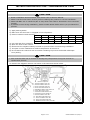
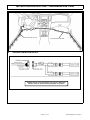
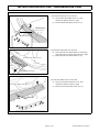
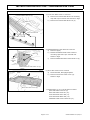
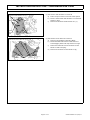
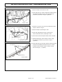
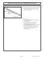
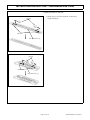
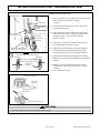
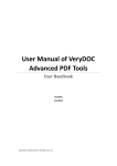
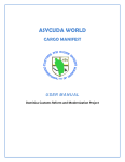
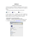
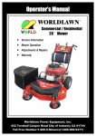
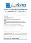
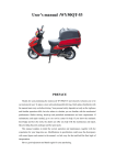
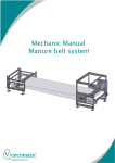
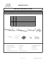
GENUINE PARTS
INSTALLATION INSTRUCTIONS
1.
2.
3.
4.
DESCRIPTION:
APPLICATION:
PART NUMBER:
KIT CONTENTS:
Illuminated Kick Plate
G37 SEDAN (2012) Starting Vin No. JN1DV6AP2CM810618
G6950 1NM0A
Item
A
B
C
D
E
F
G
H
I
QTY
1
1
2
1
14
6
9
8
1
A
B
E
5.
Description
Kick plate front LH
Kick plate front RH
Kick plate rear
Harness
Tie wrap
Urethane foam tape
Flat wire protector
Clip
Installation Instructions Replacement Template
F
C
D
H
G
I
TOOLS REQUIRED:
● Nylon Removal Tool
● Wire cutter
● 10mm Socket and driver
● 14mm socket and driver
● Fish tape
● Masking tape
● Flash light
● Scissors
● Soap and water
● 50/50 alcohol & water solution
● Soft non linting towel
page 1 of 14
G6950 1NM0A II 11/29/11
INSTALLATION INSTRUCTIONS - Illuminated Kick Plate
6.
PRE-INSTALLATION CAUTIONS/NOTES
CAUTION
● Dealer Installation Recommended. Instructions refer to Service Manual.
● Please read this instruction carefully before installing this product for correct installation.
● Please DO NOT use or install the part in ways other than what is described in this instruction
manual.
● If problem occurs during installation, please contact Nissan dealer where you purchased the
product.
1) Apply Parking Brake.
2) Make sure the shift lever is engaged in"P"or"N"position.
3) Record customer Radio Presets.
Preset
A
B
C
4)
5)
6)
7)
8)
1
2
3
4
5
6
Use seat and floor protection.
Open the hood of the vehicle.
Disconnect the negative battery terminal to prevent short circuits during installation.
This part is to be installed at a surface temperature of 65-100°F.
Do not wash the vehicle for 24 hours after installing to prevent the double-sided tape
from peeling.
CAUTION
● Care must be taken not to scratch or damage any components during the removal or
replacement process.
9) Remove the following interior trim parts in the sequence shown below.
Remove sequence
1. Rear Kick Plate Inner LH
2. Rear Kick Plate Outer LH
3. Front kick Plate Inner LH
4. Front Kick Plate Outer LH
5. Dashboard Side Lower Panel LH
6. Glove Box Lower Cover
7. Instrument Side Finisher LH
8. Instrument Lower Panel LH
9. Rear Kick Plate Inner RH
10. Rear Kick Plate Outer RH
11. Front kick Plate Inner RH
12. Front Kick Plate Outer RH
13. Dashboard Side Lower panel RH
Page 2 of 14
G6950 1NM0A II 11/29/11
INSTALLATION INSTRUCTIONS - Illuminated Kick Plate
7.
INSTALLATION OUTLINE
Short Harness for LH
8.
Long Harness for RH
STANDARD CONNECTION METHOD
Vehicle wiring color description is just for reference.
Please refer to vehicle wiring diagram for details.
Page 3 of 14
G6950 1NM0A II 11/29/11
INSTALLATION INSTRUCTIONS - Illuminated Kick Plate
9.
VEHICLE PARTS REMOVAL
Fig 1
1) Rear Kick Plate Inner LH removal
a) Pull up Rear Kick Plate Inner LH, and
disconnect pawls. Shown in Fig1.
b) Remove Rear Kick Plate Inner LH (1).
Rear Kick Plate
Inner LH (1)
pawls×8
Fig 2
2) Rear Kick Plate Outer LH removal
a) Remove Rear Kick Plate Outer LH mounting
clips with nylon removal tool. Shown in Fig2.
b) Remove Rear Kick Plate Outer LH (2).
Rear Kick Plate Outer LH (2)
clips×2
nylon removal tool
Fig 3
Front Kick Plate Inner LH (3)
3) Front Kick Plate Inner LH removal
a) Pull up Front Kick Plate Inner LH, and
disconnect pawls. Shown in Fig3.
b) Remove Front Kick Plate Inner LH (3).
pawls×10
Page 4 of 14
G6950 1NM0A II 11/29/11
INSTALLATION INSTRUCTIONS - Illuminated Kick Plate
9.
VEHICLE PARTS REMOVAL
Fig 4
4) Front Kick Plate Outer LH removal
a) Remove Front Kick Plate Outer LH mounting
clips with nylon removal tool. Shown in Fig4.
b) Remove Front Kick Plate Outer LH (4).
Fig 5
5) Dashboard Side Lower Panel LH removal
a) Remove clip(A).
b) Detach Dashboard Side Lower Panel LH
mounting clips with nylon removal tool.
Shown in Fig5.
c) Remove Dashboard Side Lower Panel LH (5).
Front Kick Plate Outer LH (4)
clips×4
nylon removal tool
clips×2
nylon
removal
tool
clip (A)
Dashboard Side Lower Panel LH (5)
Fig 6
pawls
pawls
6) Glove Box Lower Cover removal
a) Pull downward, disengaged pawls.
b) Remove Glove Box Lower Cover (6).
Shown in Fig6.
Glove Box Lower Cover (6)
7) Repeat steps 1 to 5 for RH side of vehicle
Rear Kick Plate Inner RH (9)
Rear Kick Plate Outer RH (10).
Front Kick Plate Inner RH (11).
Front Kick Plate Outer RH (12).
Dashboard Side Lower Panel RH (13).
Page 5 of 14
G6950 1NM0A II 11/29/11
INSTALLATION INSTRUCTIONS - Illuminated Kick Plate
9.
VEHICLE PARTS REMOVAL CONT'D
Instrument Side Finisher LH (7)
pawls×3
Fig 7
8) Instrument Side Finisher LH removal
a) Insert a nylon remover tool into lower space.
b) Pull the Instrument Side Finisher LH crosswise.
Shown in Fig7.
c) Remove Instrument Side Finisher LH (7).
Fig 8
9) Instrument Lower Panel LH removal
a) Remove Hood Opener Mounting Bolts.
b) Pull downward Instrument Lower Panel LH
to disengage pawls and clips. Shown in Fig8.
c) Disconnect harness from Instrument Lower
Panel LH and hose plug.
d) Remove Instrument Lower Panel LH (8).
clip
nylon
removal
tool
pawls×3
Instrument Lower Panel LH (8)
Bolts×2
pawls×3
Metal
clips×4
Page 6 of 14
G6950 1NM0A II 11/29/11
INSTALLATION INSTRUCTIONS - Illuminated Kick Plate
10.
WIRING HARNESS INSTALLATION
CAUTION
Fig 9
● Connector pull test should be less than 10kgf
Harness (D)
(22 lbs) to confirm secure connection to
vehicle connector.
Urethane foam tape (F)
1) Wrap the fuse of Harness (D) with two pieces
of Urethane foam tape (F). Shown in Fig9.
Fuse
Fig 10
2) Conect the TH04FW connector of Harness (D)
and Option connector(TH04MW) of vehicle.
Shown in Fig10.
3) Attach the Harness (D) to vehicle harness at the
position shown in Fig 10, using the Tie wrap (E).
(2 places)
Fuse
TH04MW
Vehicle
Tie wrap(E)
Harness (D)
TH04FW
Harness (D)
Fuse
Fig 11
Fuse
4) Attach the Harness (D) to vehicle harness at the
position shown in Fig11, Secure by using the Tie
wrap (E) - (2 places)
Tie wrap (E)
Harness (D)
Page 7 of 14
G6950 1NM0A II 11/29/11
INSTALLATION INSTRUCTIONS - Illuminated Kick Plate
10.
WIRING HARNESS INSTALLATION CONT'D
Fig 12
6) Route Harness (D) under accelerator pedal bracket,
and attach harness to floor using the Flat wire
protector (G) shown in Fig12. (4 places)
Harness (D)
Flat wire protector (G)
Driver's side
Fig 13
Push nut
5) Flip the carpet of the driver's side.
Harness(D)
7) Remove one push nut from front passenger's side
carpet. Shown in Fig13.
8) Flip the carpet of passenger's side.
9) Route fish tape behind center console from
driver's side harness to passenger's side.
10) Pull harness with fish tape behind center console.
Flat wire protector(G)
11) Attach passenger's side harness to floor using
the Flat wire protector (G) shown in Fig13.
(5 places)
Passenger's side
Fig 14
Tie wrap (E)
12) Route Harness (D) through existing vehicle harness
protector and attach the Harness (D) to vehicle
harness at the position shown in Fig14, using
the Tie wrap (E) - (3 places)
Harness (D)
Driver's side
Page 8 of 14
G6950 1NM0A II 11/29/11
INSTALLATION INSTRUCTIONS - Illuminated Kick Plate
10.
WIRING HARNESS INSTALLATION CONT'D
Fig 15
13) Route Harness (D) through existing vehicle harness
protector and attach the Harness (D) to vehicle
harness at the position shown in Fig15, using
Tie wrap (E) - (3 places)
Harness (D)
Tie wrap (E)
Passenger's side
14) Function check
a) Connect Harness (D) to the lamp unit harness of
Kick plate (A) and (B).
b) Connect battery.
c) Check function. Confirm "INFINITI" text
illuminates when either door is open.
d) If OK, disconnect Harness (D) from the lamp unit
harness of Kick plate (A) and (B).
e) If NG, check harness routine, connections
and lamp unit to identify root cause and fix it.
Repeat steps (A) to (C) until it is OK.
f) Disconnect battery.
Page 9 of 14
G6950 1NM0A II 11/29/11
INSTALLATION INSTRUCTIONS - Illuminated Kick Plate
11.
CLIP TO A KICK PLATE INSTALLATION
The procedure below shows the installation for LH side.
Repeat procedure for RH side.
Fig 16
Clip (H)
1) Slide clip (H) into the Clip Seat, as shown in
Fig16 and Fig17.
Clip Seat
Kick plate front (A)
Fig 17
Clip (H)
Clip Seat
Kick plate rear (C)
Page 10 of 14
G6950 1NM0A II 11/29/11
INSTALLATION INSTRUCTIONS - Illuminated Kick Plate
12.
FRONT KICK PLATE INSTALLATION
The procedure below shows the installation for LH side.
Repeat procedure for RH side.
Fig 18
FRONT
Weather strip
1) Remove the vehicle weather strip near the Kick
plate front (A) attachment location shown in Fig18.
2) Clean the attachment area of Kick plate front (A)
with soapy water.
3) Dry area with soft non linting towel.
4) Clean area with 50/50 alcohol & water solution
and let dry for 30 seconds.
Fig 19
Kick plate front LH (A)
Masking tape
Tape's Liner
5) Pull the double-sided tape liner pull tab to
partially remove liner.
Using masking tape, hold the liner to the visible
side of the Kick plate front (A) surface as shown
in Fig19.
6) Align clips on part to first and fourth hole on
vehicle from front side.
7) Set part on vehicle, being careful to keep the
outside edge of the part parallel to the rocker
panel.
8) Gradually remove the tape liner at the back of
the Kick plate front (A) starting from the front,
apply minimum 11lb (49N) of pressure along
the part to attach tape to body shown in Fig19.
Masking tape
Kick plate front LH (A)
Keep Kick Plate(A) and vehicle body parallel.
CAUTION
● Use caution when applying pressure as the surface may dent.
● During installation, be careful not to allow the harness to get stuck between the vehicle and the
kick plate.
● Harness should be routed through the notched area of the kick plate.
Page 11 of 14
G6950 1NM0A II 11/29/11
INSTALLATION INSTRUCTIONS - Illuminated Kick Plate
13.
HARNESS CONNECTION INSTALLATION
The procedure below shows the installation for LH side.
Repeat procedure for RH side.
Fig 20
Kick plate LH (A)
FRONT
Tie wrap (E)
2) Fold one piece Urethane foam tape (F) and cut
into two equal pieces.
Excessive lamp
Harness
Kick plate LH (A)
1) Secure harness (D) to vehicle harness at connector
with Tie Wrap (E) as shown in Fig20.
(1 place)
3) Clean both sides of the attachment area for the
Urethane foam tape (F) with the 50/50 alcohol
& water solution. Let dry for 30 seconds.
Shown in Fig20.
Connector
Lamp Unit
Harness
4) Attach the cut piece of Urethane foam tape (F)
to vehicle flange as shown in Fig21.
Urethane foam tape (F)
(Reference "Detail A")
5) Place the lamp harness on top of the Urethane
foam tape (F), then apply second half of the
Urethane foam tape (F) on top of the harness.
Detail A
Harness routing of Vehicle Flange
FRONT
6) Connect the connectors and apply the Urethane
foam tape (F) on the connecting section as shown
in Fig21.
Diagonally
Straight
Vehicle Flange
Urethane foam tape (F)
Lamp Unit
Harness
OK
7) Attach excessive lamp harness to the vehicle
harness with a Tie wrap (E) as shown in Fig20.
(1 place)
8) Cut excessive Tie wrap.
NG
Fig 21
Urethane foam tape (F)
Lamp Unit
Harness
Vehicle Flange
Connector
Urethane foam tape (F)
CAUTION
● Do not attach the harness to sharp metal edge.
Page 12 of 14
G6950 1NM0A II 11/29/11
INSTALLATION INSTRUCTIONS - Illuminated Kick Plate
14.
REAR KICK PLATE INSTALLATION
The procedure below shows the installation for LH side.
Repeat procedure for RH side.
Fig 22
FRONT
Weather strip
1) Remove the vehicle weather strip near the Kick
plate rear (C) attachment location as shown in
Fig22.
2) Clean the attachment area of Kick plate rear (C)
with soapy water.
3) Dry area with soft non linting towel.
4) Clean area with 50/50 alcohol & water solution
and let dry for 30 seconds.
Fig 23
Kick plate rear (C)
5) Pull the double-sided tape liner pull tab to
partially remove liner. Using masking tape,
hold the liner to the visible side of the Kick plate
rear (C) surface as shown in Fig23.
6) Align clips on part to hole on vehicle from
front side.
Masking tape
7) Set part on vehicle, being careful to keep the
outside edge of the part parallel to the rocker
panel.
Tape's Liner
9) Gradually remove the tape liner at the back of
the Kick plate rear (C) starting from the front, apply
minimum 11lb (49N) of pressure along the part
to attach tape to body as shown in Fig23.
Masking tape
Kick plate rear (C)
C Kick Plate RH
Keep Kick plate rear (C) and vehicle body parallel.
CAUTION
● Use caution when applying pressure as the surface may dent.
Page 13 of 14
G6950 1NM0A II 11/29/11
INSTALLATION INSTRUCTIONS - Illuminated Kick Plate
14.
CHECK AFTER INSTALLATION
1) Please check that the installation has no problem.
□ a) confirm connection of connector
□ b) confirm whether wire harness is fixed.
15.
FUNCTION CHECK
□ 1) Re-connect battery negative terminal.
□ 2) Confirm all switch function are working on Instrument Lower Panel LH.
□ 3) Confirm "INFINITI" text is illuminated when either door is in the opened position. Manual engage door
switch to verify Illuminated Kick Plate ON/OFF function is working.
16.
REINSTALLATION OF REMOVED PARTS
□ 1) All removed vehicle parts have been reinstalled.
CAUTION
● Use caution when re-installing interior components to avoid damage, scratch, or breaking of
mounting clips.
□ 2) Clean interior of vehicle.
17.
VEHICLE CHECK
□ 1)
□ 2)
□ 3)
□ 4)
□ 5)
□ 6)
□ 7)
□ 8)
□ 9)
□ 10)
□ 11)
Remove all tools from the vehicle.
Inspect reinstalled interior trim parts for proper panel fit.
Reset radio presets to the recorded setting.
Turn ignition to ON position.
Confirm proper radio operation.
Initialize sun roof, and power window operation.
Confirm proper operation of the rear window washer fluid.
Confirm the functionality of all four blinkers and hazard warning signal flasher.
Confirm the operation of all door lock and unlock using remote key.
Reset windows. When window is completely up, continue to hold in up position for 4 seconds.
Turn ignition to off position.
CAUTION
● During restoring, please use caution to avoid the pinching or breaking of the vehicle's harness,
or damage any other parts.
Page 14 of 14
G6950 1NM0A II 11/29/11